

Pioneer ES Series, PB Series, PEB Series Operation & Maintenance Manual

Pioneer Self Priming Series
ES Series
Operation & Maintenance Manual
Manual #6001
310 South Sequoia Parkway
Corporate Office
Canby, OR 97013
Phone (503) 266-4115
Fax (503) 266-4116
Revision0049/21/2018

TABLE of CONTENTS
TABLEOFCONTENTS........................................................................................................................................2
INTRODUCTION................................................................................................................................................3
INSPECTION.....................................................................................................................................................3
PRE‐INSTALLATIONINSPECTION............................................................................................................................3
OILLEAKAGECHECK............................................................................................................................... ................4
RECORDINGMODEL&SERIALNUMBERS...............................................................................................................4
WARRANTYINFORMATION....................................................................................................................................4
SAFETYINFORMATION...........................................................................................................................................5
INSTALLATION.................................................................................................................................................6
FOUNDATION/BASEPLATE/SKID............................................................................................................................6
LEVELING................................................................................................................................................................6
GROUT...................................................................................................................................................................7
TRAILERMOUNTEDUNITS.....................................................................................................................................7
INSTALLINGPUMP.................................................................................................................................................7
SUCTIONPIPING.....................................................................................................................................................7
PRODUCTFLUSH....................................................................................................................................................7
DISCHARGEPIPING.................................................................................................................................................8
SUCTION&DISCHARGEPIPEFLANGES...................................................................................................................8
SCREENING.............................................................................................................................................................9
SUMPDESIGN........................................................................................................................................................9
LIFTING...................................................................................................................................................................9
ALIGNMENTOFPUMPANDMOTOR......................................................................................................................9
ROTATION............................................................................................................................................................10
OPERATION...................................................................................................................................................10
PRE‐STARTCHECKLIST.........................................................................................................................................10
LUBRICATION.......................................................................................................................................................10
PRIMING...............................................................................................................................................................10
OPERATIONOFENGINEDRIVENUNITS................................................................................................................11
STARTING.............................................................................................................................................................11
ROTATION...............................................................................................................................................................12
LIQUIDTEMPERATUREANDOVERHEATING.....................................................................................................................12
PUMPVACUUMCHECK..............................................................................................................................................12
STOPPING.............................................................................................................................................................12
MAINTENANCE..............................................................................................................................................13
SPAREPARTS........................................................................................................................................................13
DISASSEMBLY.......................................................................................................................................................15
INSPECTIONCOVERANDWEAR...........................................................................................................................15
SUCTIONCHECKVALVE........................................................................................................................................15
ROTATINGASSEMBLY..........................................................................................................................................15
IMPELLER.............................................................................................................................................................16
MECHANICALSEAL...............................................................................................................................................16
PRESSURERELIEFVALVE......................................................................................................................................19
LUBRICATION.......................................................................................................................................................19
PUMPSTORAGE.............................................................................................................................................20
TROUBLESHOOTING......................................................................................................................................20
CONDITIONSANDTERMSOFSALE.................................................................................................................22
2

INTRODUCTION
Thank you for purchasing a Pioneer Elite Series Self-Priming centrifugal pump, complete with
integral suction check valve. The pump is designed for handling non-volatile, non-flammable,
mild industrial corrosives, residues and slurries containing large entrained solids. The Pioneer
Elite Self-Priming Pump series is designed to be a direct bolt in replacement for the Pioneer
Self-Priming Pump series.
WARNING!!!
This manual provides installation, operation and maintenance instructions for your Pioneer
Self-Prime Pump and is intended to make your personnel aware of any procedure that requires
special attention because of potential hazards to personnel or equipment. Read all instructions
carefully and remember, pump installations are seldom identical. Therefore, this manual
cannot possibly provide detailed instructions and precautions for each specific application.
Thus, it is the owner/installer’s responsibility to ensure that neither operator safety nor pump
integrity are compromised by installations and applications that are not addressed in this
manual.
WARNING!!!
Centrifugal Pumps are designed for specific service and may or may not be suited for any other
service without loss of performance or potential damage to equipment/personnel. If there is
ever any doubt about suitability for a specific purpose; contact your Pioneer Pump, Inc.
representative or the factory for assistance.
Remember: Pump performance may be affected by changes in pumpage such as, specific
gravity, viscosity, temperature, operating speed and net positive suction head available
(NPSHA).
INSPECTION
The pump assembly was inspected and tested before shipment from the factory. Before
installation, inspect the pump for damage that may have occurred during shipment.
PRE-INSTALLATION INSPECTION
Check as follows: Inspect the pump for cracks, dents, damaged threads, and other obvious
damage.
Check for and tighten loose attaching hardware. Since gaskets tend to shrink after drying,
check for loose hardware at mating surfaces.
Carefully read all warnings and cautions contained in this manual or affixed to the pump, and
perform all duties indicated. Note the direction of rotation indicated on the pump and check
that the pump shaft rotates counter-clockwise when standing on the suction side of the pump
and facing the impeller.
3

OIL LEAKAGE CHECK
The bearing oil and mechanical seal oil are
each sealed by a shaft lip seal, and a vent
to atmosphere exists between these two lip
seals to indicate oil leak from either cavity.
If either the bearing oil or mechanical seal
oil lip seal leaks, oil will leak from the
vent. This vent should be checked for
leakage prior to pump operation.
CAUTION!!!
If equipment is stored more than twelve (12) months, some of the components or lubricants
may have exceeded their maximum shelf life. These must be inspected and replaced as
necessary prior to pump operation to ensure proper pump performance.
RECORDING MODEL & SERIAL NUMBERS
Record the model and serial number for your Pioneer Pump in the spaces provided below.
The factory will need this information when you require parts or service.
PumpModel:____________________________________
PumpSerialNumber:_______________________________
Engine/MotorSerial#_______________________________
Engine/Motor Mgf: __________________________________
WARRANTY INFORMATION
Pioneer Pump’s current terms and
website http://www.pioneerpump.com from the homepage by selecting More > Resources > Terms and
Conditions or by following this link:
http://pioneerpump.com/media/232391/M5132_Pioneer_Standard_Terms_and_Conditions-1-.pdf
conditions, including limited warranty policy, can be found on our
4

ARRANTY CLAIMS
W
Contact the factory to file a warranty claim, before shipping parts back. Parts returned to the
factory without an RMA number on file will be scrapped upon arrival.
SAFETY INFORMATION
These warnings apply to Elite Series basic pumps. In many cases, Pioneer Pump, inc. has no
control over or particular knowledge of the power source that will be used. Therefore, refer to
the manual accompanying the power source before attempting to begin operation.
WARNING!!!
Before attempting to open or service the pump:
1. Familiarize yourself with this manual.
2. Disconnect or lock out the power source to ensure that the pump will remain
inoperative.
3. Check the temperature before opening any covers, plates or plugs.
4. Allow the pump to cool if overheated.
5. Close the suction and discharge valves.
6. Vent the pump slowly and cautiously.
7. Drain the Pump.
WARNING!!!
This pump is designed to handle mild industrial corrosives, residues and slurries containing
large entrained solids. Do not attempt to pump volatile, corrosive, or flammable materials that
may damage the pump or endanger personnel as a result of pump failure.
WARNING!!!
After the pump has been positioned, make certain that the pump and all piping connections are
tight, properly supported and secure before operation. (Refer to Installation section)
DANGER!!!
Do not operate the pump without the guards in place over the rotating parts. Exposed rotating
parts can catch clothing, fingers, or tools, causing severe injury to personnel.
5

WARNING!!!
Do not remove plates, covers, gauges, pipe plugs, or fittings from an overheated pump. Vapor
pressure within the pump can cause parts being disengaged to be ejected with great force.
Allow the pump to cool before servicing.
WARNING!!!
Do not operate the pump against a closed discharge valve for long periods of time. If operated
against a closed discharge valve, pump components will deteriorate, and the liquid could come
to a boil, build pressure, and cause the pump casing to rupture or explode.
WARNING!!!
Remove suction and discharge piping from pump prior to moving. Use lifting and moving
equipment with adequate capacity and in good repair.
INSTALLATION
Use the following guidelines when installing your new Elite Series Self Priming Pump.
WARNING!!!
Review safety information in safety information section. This section is intended to outline
general recommendations and practices required to position and arrange the pump and piping
in static lift situations. If installing the unit in flooded suction applications some of the
information will need to be tailored to the specific application. Never exceed the maximum
permissible operating pressure of the pump as shown on the pump performance curve.
FOUNDATION/BASE PLATE/SKID
If using a concrete foundation it should be rigid enough to inhibit vibration. Pour the
foundation well in advance of installation of pump equipment to allow time for drying and
curing.
If the pump is to be mounted on a steel frame, or similar structure, it should be set directly over
the supporting beams. These beams and the structure must be rigid enough to prevent
distortion and potential misalignment due to movement within the structure or base.
The location of this structure should be as close as possible to the pumpage source. Provide
adequate space for operation, maintenance and inspection of the pump and equipment.
The concrete foundation should be provided with anchor bolts for attachment to the base plate.
If required, provide adequate drainage to keep pump and motor dry and clean. Also, provide
either leveling nuts or leveling wedges for mounting the base plate to the foundation.
LEVELING
When mounting the base plate to the foundation use the leveling nuts or wedges to provide a
level, flat base plate. Use a machinist's level on the mounting pads and make adjustments as
6

necessary as the anchor bolts are tightened. This will provide the true alignment between the
pump and motor.
GROUT
If this base plate is to be grouted, ensure that you have the mounting surface flat and level for
correct alignment of pump and motor. Build a dam around the base plate perimeter that is to be
watertight. Use standard grouting practice and be sure to protect (cover) the leveling wedges
with caulk or plastic tape if they are to be removed later. After the grout has thoroughly
hardened, remove forms. If the wedges are removed, fill holes with grout. Seal grout by
covering with a quality paint or sealer.
TRAILER MOUNTED UNITS
See “OPERATION” section.
INSTALLING PUMP
Ensure that all foreign material has been removed from the pump before mounting. Be sure to
remove all shipping protection prior to operation.
NOTE: Many of the bare pumps are shipped with protective guards and coatings.
SUCTION PIPING
For best performance the suction piping should be at least as large as the pump flange, never
smaller. Use an eccentric reducer at the suction flange with the straight side up. The use of
flow-retarding fittings is to be avoided and if necessary should never be placed closer to the
pump suction than four (4) times the pipe diameter. The pump should be at the highest point of
the piping. Slope the piping up to the pump to prevent air pockets and avoid changing pipe
size with the exception of the eccentric reducer mentioned above. All suction piping and
fittings are to be checked for any foreign material (rocks, bolts, wire, etc.) and also any sharp
burrs that could disrupt the flow.
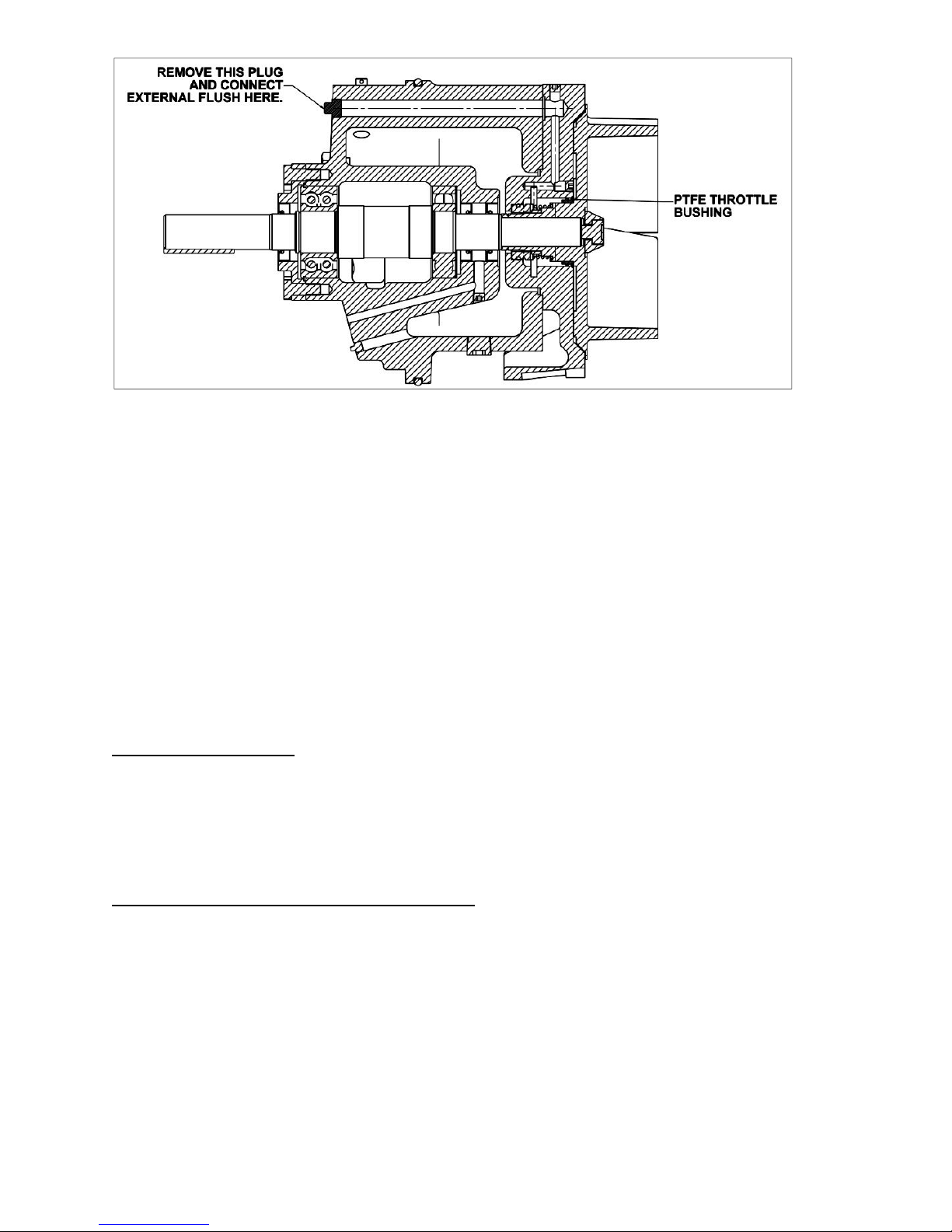
PRODUCT FLUSH
With the throttle bushing installed, remove the ½ NPT pipe plug above the shaft at the drive
end of the bearing housing. Connect a water source to the ½” NPT port that maintains no less
than 50% of the discharge pressure. Water will flow through the seal housing into the pumpage
to keep it from entering the seal housing.
7
CAUTION!!!
The suction and discharge pipe/hose material should be compatible with the liquid being
pumped.
CAUTION!!!
If hose is used on the suction line it should be of the reinforced type to prevent collapse under
suction lift.
DANGER!!!
If a manual shut-off valve is installed in the discharge line, it must not be left closed during
operation, a closed manual shut off valve will cause overheating and possible explosive rupture
of the pump casing. Personnel could be severely injured!
DISCHARGE PIPING
Use a concentric taper on the discharge side to increase discharge pipe diameters. All valving
and additional fittings should be the same size as the discharge main-line. The discharge size
should be adequate to maintain reasonable velocities and reduce friction losses. It is strongly
recommended that a pressure relief valve is installed on the discharge piping.
SUCTION & DISCHARGE PIPE FLANGES
All piping is to be supported, braced and lined up square before connection to the pump
flanges. A flexible fitting is recommended on both suction and discharge, to eliminate
misalignment loads or stresses being transmitted to the pump.
NOTE: Flexible pipe couplings must be restrained so as not to transmit any strain to the pump
flanges when expanding or contracting under pressure. Unrestrained expansion fittings can
transmit enormous forces to the pump flanges.
8
 Loading...