

Page 1
ORDER NO.
RRV2479
STEREO POWER AMPLIFIER
M-L11
THIS MANUAL IS APPLICABLE TO THE FOLLOWING MODEL(S) AND TYPE(S).
Model
M-L11
MYXJ AC220–230V
NVXJ AC230V
¶ This product is a system(s) component.
This product does not function properly independently ; to avoid malfunctions, be
sure to connect it to the prescribed system component(s), otherwise damage may
result.
¶ Please connect it to the STEREO CD TUNER XC-L11, for adjustment and operation
inspection.
RemarksPower RequirementType
Component Model Service manual Remarks
STEREO CD TUNER XC-L11 RRV2470
STEREO POWER AMPLIFIER M-L11 RRV2479 This manual.
SPEAKER SYSTEM S-L11-Q-LRW S-L11-S-LRW RRV2483, RRV2484
STEREO CASSETTE DECK CT-L11 RRV2471
MINIDISC RECORDER MJ-L11 RRV2472
CONTENTS
1. SAFETY INFORMATION....................................2
2. EXPLODED VIEWS AND PARTS LIST .............3
3. BLOCK DIAGRAM AND SCHEMATIC DIAGRAM
.........................................................8
4. PCB CONNECTION DIAGRAM .......................14
5. PCB PARTS LIST.............................................20
6. ADJUSTMENT.................................................. 22
PIONEER CORPORATION 4-1, Meguro 1-chome, Meguro-ku, Tokyo 153-8654, Japan
PIONEER ELECTRONICS SERVICE, INC. P.O. Box 1760, Long Beach, CA 90801-1760, U.S.A.
PIONEER EUROPE NV Haven 1087, Keetberglaan 1, 9120 Melsele, Belgium
PIONEER ELECTRONICS ASIACENTRE PTE. LTD. 253 Alexandra Road, #04-01, Singapore 159936
PIONEER CORPORATION 2001
7. GENERAL INFORMATION ..............................23
7.1 DIAGNOSIS................................................23
7.1.1 DISASSEMBLY .................................23
7.1.2 SINGLE OPERATION METHOD ...... 24
8. PANEL FACILITIES AND SPECIFICATIONS
....................................................................26
T–ZZK JULY 2001 Printed in Japan
Page 2

M-L11
1. SAFETY INFORMATION
LITHIUM BATTERY NOTICE
WARNING!
Lithium batteries. Danger of explosion. Replacement must be done by
qualified personnel and only by following the instructions given in the
service manual.
This warning is stated on the product or in the operating instructions.
When replacing the lithium batteries, follow the note below.
Dispose of the used battery promptly. Keep away from children. Do
not disassemble and do not dispose of in fire.
The battery used in this device may present a fire or chemical hazard
if mistreated. Do not recharge, disassemble, heat above 100 ˚C or
incinerate. Replace only with the same Part Number. Use of another
battery may present a risk of fire or explosion.
Note: The lithium battery installation position is shown in the
exploded views.
ADVARSEL!
Lithiumbatteri − Eksplosionsfare ved
fejlagtig håndtering. Udskiftning må kun
ske med batteri af samme fabrikat og
type. Levér det brugte batteri tilbage til
leverandøren.
Denne advarsel or angivet på produktet eller i brugsvejledningen.
Ved udskiftning af lithium batterierne følges nedenstående
anveisning.
Batterierne må kun udskiftes med batterier af samme type og
mærke.
2
Page 3
18
13
6
7
(MYXJ only)
19
1
15
16(1/2)
20
(MYXJ only)
3 (MYXJ type)
FRONT
3 (NVXJ type)
21
(MYXJ only)
13
2
8
14
14
10
11
12
5
9
4
17
16(2/2)
2. EXPLODED VIEWS AND PARTS LIST
NOTES : Parts marked by “ NSP ” are generally unavailable because they are not in our Master Spare Parts List.
The mark found on some component parts indicates the importance of the safety factor of the part.
Therefore, when replacing, be sure to use parts of identical designation.
Screw adjacent to mark on the product are used for disassembly.
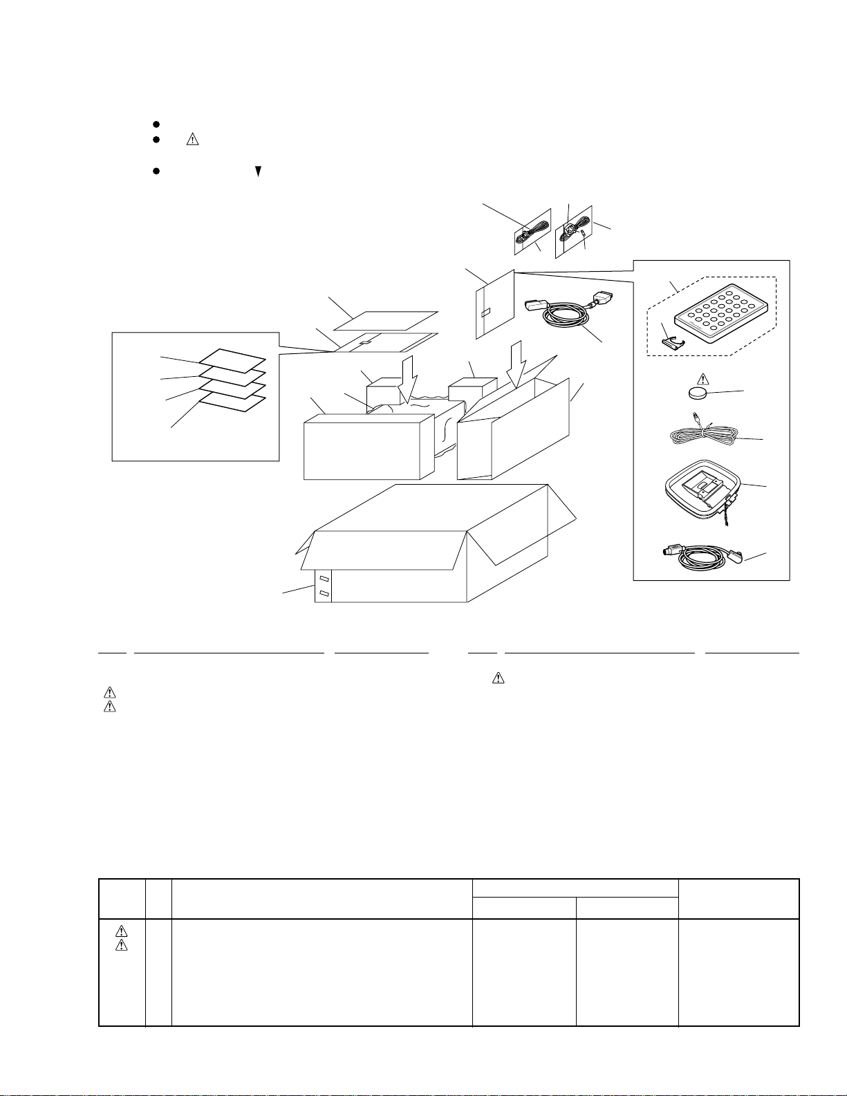
2.1 PACKING
M-L11
(1) PACKING PARTS LIST
Mark No. Description Part No.
1 System Cable (20P) ADE7057
2 Display cable (10P) ADE7077
3 AC Power Cord
4 Fuse (T5A)
5 FM Wire Antenna ADH7005
6 Operating Instructions ARE7277
(English/French)
7 Operating Instructions
NSP 8 Warranty Card ARY7022
9 Loop Antenna ATB7009
10 Remote control Unit AXD7306
(2) CONTRAST TABLE
MYXJ type and NVXJ type are constructed the same except for the following:
Mark
No.
3 AC Power Cord ADG1154 ADG1156
4 Fuse (T5A) Not used AEK7001
7 Operating Instructions (Spanish/Dutch) ARC7337 Not used
18 Packing Case AHD8002 AHD8001
20 Operating Instructions (German/Italian) ARC7375 Not used
21 Operating Instructions (Swedish/Portuguese) ARC7376 Not used
Symbol and Description
See Contrast table (2)
See Contrast table (2)
See Contrast table (2)
Mark No. Description Part No.
11 Battery Lid AZN7834
NSP 12 Lithium Battery (CR2025) VEM1009
13 Vinyl Bag (115 × 270 × 0.05) Z21–013
NSP 14 Polyethylene Bag Z21–038
(0.03 × 230 × 340)
15 Front Pad A AHA7368
16 Rear Pad A AHA7369
17 Spacer AMP AHB7058
18 Packing Case
19 Sheet Z23–026
20 Operating Instructions
21 Operating Instructions
Part No.
MYXJ type NVXJ type
See Contrast table (2)
See Contrast table (2)
See Contrast table (2)
Remarks
3
Page 4
M-L11
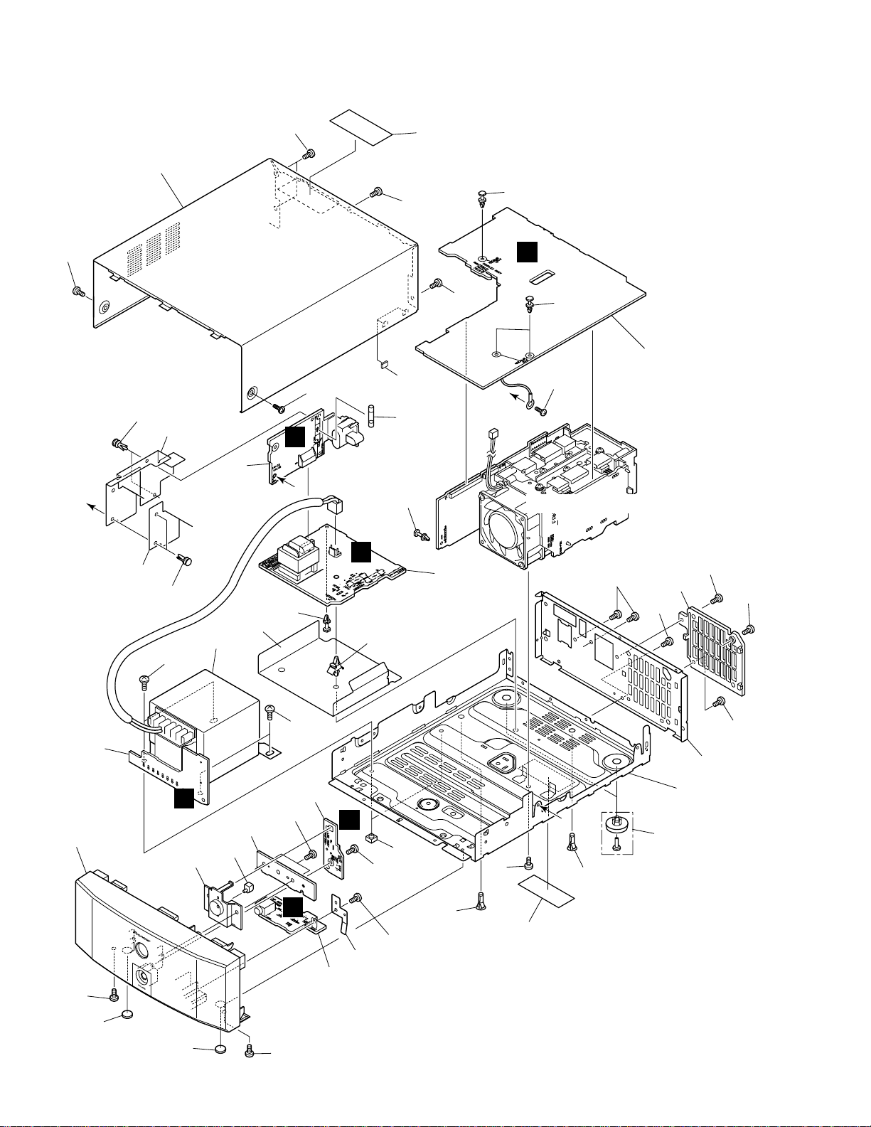
2.2 EXTERIOR
27
30
21
18
A
30
29
Note: when you order the bonnet (No.27),
please order Caution Label (No.29) too
and paste it to the bonnet.
30
16
H
30
30
33
B
8
16
4
30
A
1
A
16
Refer to "2.3 HEAT SINK ASSY".
25
30
B
20
21
24
17
7
32
32
3
C
12
Holder Unit
26
5
31
19
F
31
E
31
11
6
22
2
B
30
15
28
31
30
23
15
13
31
31
31
10
9
14
14
30
4
Page 5
(1) EXTERIOR SECTION PARTS LIST
Mark No. Description Part No.
M-L11
Mark No. Description Part No.
1 AC IN Assy AWU7556
2 PRIMARY Assy AWU7557
3 SECONDRY Assy AWU7558
4 COMPLEX Assy AWU7559
5 LED Assy AWU7562
6 HP Assy AWU7563
7 Power Transformer (T1) ATS7278
8 Fuse (FU1) (T2AL250V) REK1025
NSP 9 Chassis ANA7110
10 Rear Panel ANC8029
11 Erath Plate ANG7331
12 Lens Bracket AAK7766
13 Rear Mold AAX7803
14 Leg AEB7090
15 PCB Holder AEC7057
NSP 16 PCB Spacer (3×6) AEC7156
17 Bottom Barrier AEC7283
18 Side Barrier AEC7285
NSP 19 PCB Spacer AEC7289
20 Sub Barrier AEC7312
21 Nylon Rivet AEC7315
22 Disc Guard PNM1245
23 Foot (Rubber) REC-434
NSP 24 Card Spacer REC1156
25 Front Panel AMB7702
26 LED Lens PNW2019
27 Bonnet AZN7837
NSP 28 Label
29 Caution Label ARW7146
30 Screw BBZ30P080FNI
31 Screw BPZ30P100FZK
32 Screw FBT40P060FCC
33 Spacer AEB7224
See Contrast table (2)
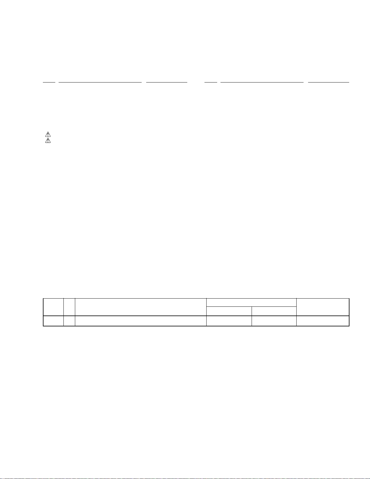
(2) CONTRAST TABLE
MYXJ type and NVXJ type are constructed the same except for the following:
Symbol and DescriptionNo.Mark
NSP 28 Label ARW7134 ARW7133
MYXJ type NVXJ type
Part No.
Remarks
5
Page 6
M-L11
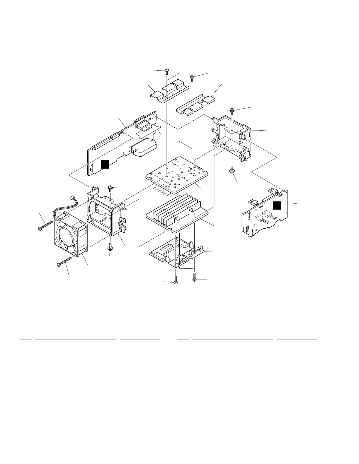
2.3 HEAT SINK ASSY
12
G
10
5
1
7
9
10
5
9
8
9
6
D
6
2
12
8
9
3
11
4
11
• HEAT SINK ASSY SECTION PARTS LIST
Mark No. Description Part No. Mark No. Description Part No.
1 AMP Assy AWU7560
2 REG Assy AWU7561
3 DC Fan Motor AXM7014
4 Power Pac Holder ANG7109
5 Heat Plate ANG7328
6 Heat Sink ANH7132
7 Mica Sheet AEE7036
8 Fan Mold AMR7321
9 Screw ABA1021
10 Screw BBZ30P080FNI
11 Screw BBZ30P160FMC
12 Screw BPZ30P350FZK
6
Page 7

M-L11
7
Page 8

1
234
M-L11
3. BLOCK DIAGRAM AND SCHEMATIC DIAGRAM
Note: When ordering service parts, be sure to refer to "EXPLODED VIEWS AND PARTS LIST" or "PCB PARTS LIST".
3.1 BLOCK DIAGRAM and OVERALL CONNECTION DIAGRAM
A
: AUDIO SIGNAL ROUTE
PRIMARY ASSY
(AWU7557)
B
IC41
T1 POWER TRANSFORMER
B
H
COMPLEX ASSY
(AWU7559)
D3001
D11
D21
C
SECONDRY ASSY
LIVE
NEUTRAL
(AWU7558)
C
D
A
AC IN ASSY
(AWU7556)
8
1234
LED ASSY
(AWU7562)
AC POWER
CORD
F
E
HP ASSY
(AWU7563)
G
AMP ASSY
(AWU7560)
(HP)(HP)
(HP)
(HP)
Page 9

5
67
8
M-L11
IC31
REG ASSY
(AWU7561)
D
The power supply is shown
with the marked box.
(C)
A
B
AKE1025
(C)
65
BALANCED
7
BUFFER
2
IC3021
7
(C)
(C)
3
LPF
16
2
(C)
(C)
7
(C)
14
(C)
C
To STEREO CD TUNER XC-L11
17
5
7
D
(HP)(HP)
9
5
6
7
8
Page 10

1
234
M-L11
3.2 AC IN, PRIMARY and SECONDRY ASSYS
A
CAUTION : FOR CONTINUED PROTECTION AGAINST RISK OF FIRE.
REPLACE WITH SAME TYPE NO. 491010 MFD. BY
LITTELFUSE INC. FOR IC11 and IC12 (AEK7068).
SECONDRY ASSY
C
(AWU7558)
CAUTION : FOR CONTINUED PROTECTION AGAINST RISK OF FIRE.
REPLACE WITH SAME TYPE NO. 491007 MFD. BY
LITTELFUSE INC. FOR IC13 and IC14 (AEK7047).
CAUTION : FOR CONTINUED PROTECTION AGAINST RISK OF FIRE.
REPLACE WITH SAME TYPE NO. 49102.5 MFD. BY
LITTELFUSE INC. FOR IC15 (AEK7049).
T1 POWER TRANSFORMER
ATS7278
230V:
MYXJ, NVXJ
J15
H
B
PRIMARY ASSY
(AWU7557)
B
T2:
ATT7050
CN4
+12V +5.6V
CN11
H
CN41
1000/16
C
CN3
J41
CN2
A
AC IN ASSY
(AWU7556)
AN1
BKP1046
AN1
D
(T2A) REK1025
NOTE FOR FUSE REPLACEMENT
CAUTION: FOR CONTINUED PROTECTION
AGAINST RISK OF FIRE.
REPLACE ONLY WITH SAME
TIME AND RATINGS ONLY.
AC220–230V 50/60Hz: MYXJ
AC230V 50/60Hz: NVXJ
AC POWER CORD
ADG1154: MYXJ
ADG1156: NVXJ
10
A
B
1234
C
Page 11

1
3.3 REG, HP and LED ASSYS
23
4
M-L11
H
CN52
D
+21V
REG ASSY
(AWU7561)
–18V
A
+18V
33/50
2.2k
33/50
0
B
G
J3953
CN51
CN3953
V+12
(HP)
6.8k
3.9k
1k
MTZJ6.8B
(HP) (HP)
33/50
C
F
LED ASSY
(AWU7562)
1K
CN5601
V+12
D
HP ASSY
E
(AWU7563)
D
1
2
3
E
F
4
11
Page 12

1
234
M-L11
3.4 AMP and COMPLEX ASSYS
A
SIGNAL ROUTE
: AUDIO SIGNAL
(C)
: AUDIO SIGNAL (CENTER)
(HP)
: AUDIO SIGNAL (HEADPHONE)
BALANCED BUFFER
5V
8.8V
CN3012
–8.8V
B
(HP) (HP)
(HP)
–8.8V
C
D
AMP ASSY
(AWU7560)
G
8.8V
(C)
28V
330330
–28V
–28V
(HP)
CN5802
0
R5699
(C)
(C)
(C)
28V
(C)
J3953
(HP)
V+12
12
CN3953
E
G
1234
Page 13

5
67
8
M-L11
CN51
D
CN11
J15
C
CN3011
CN52
B
J41
CN41
1SS355
5V
The power supply is shown
with the marked box.
CN3001
A
B
To STEREO CD TUNER XC-L11
(C) (C)
CN5801
CN3651
CN3801
AKE1025
(C)
∗
L3081–L3083: ATH–059
R3081–R3083: 100
(C)
(C)
CN3802
C
D
To FAN MOTOR
5
COMPLEX ASSY
(AWU7559)
H
H
6
7
8
13
Page 14

1
234
M-L11
4. PCB CONNECTION DIAGRAM
NOTE FOR PCB DIAGRAMS:
1. Part numbers in PCB diagrams match those in the schematic
diagrams.
A
2. A comparison between the main parts of PCB and schematic
diagrams is shown below.
Symbol in PCB
Diagrams
BCE
BCE
DGS
Symbol in Schematic
Diagrams
BCE
BCE
BCEBCE
DGSDGS
Part Name
Transistor
Transistor
with resistor
Field effect
transistor
4.1 AC IN, PRIMARY and SECONDRY ASSYS
B
SIDE A
Symbol in PCB
Diagrams
3. The parts mounted on this PCB include all necessary parts
for several destination.
For further information for respective destinations, be sure
to check with the schematic diagram.
4. Viewpoint of PCB diagrams
P. C. Board Chip Part
Symbol in Schematic
Diagrams
CapacitorConnector
PRIMARY ASSY
B
Part Name
Resistor array
3-terminal
regulator
SIDE A
SIDE B
H
CN41
C
C
SECONDRY ASSY
(ANP7345–E)
H
CN11
POWER
TRANSFORMER
IC12
IC15
IC11
IC13
IC14
IC41
(ANP7345–E)
A
AC IN ASSY
NEUTRAL
D
AC POWER CRD
LIVE
(ANP7345–E)
14
A
B
1234
C
Page 15

1
23
4
M-L11
A
SIDE B
Q42
Q41
PRIMARY ASSY
B
C
SECONDRY ASSY
B
C
(ANP7345–E)
(ANP7345–E)
A
AC IN ASSY
D
(ANP7345–E)
A
1
2
3
B
C
4
15
Page 16

1
234
M-L11
4.2 COMPLEX, AMP, REG, HP and LED ASSYS
SIDE A
A
D
REG ASSY
IC31
Q54
Q52
Q51
B
Q55
H
COMPLEX ASSY
Q57
Q53
IC53
(ANP7345–E)
C
Front
IC54
D
(ANP7345–E)
C
J15
16
D
H
1234
Page 17

5
67
8
M-L11
SIDE A
A
G
AMP ASSY
IC3401
IC3301
B
F
LED ASSY
To FAN MOTOR
B
J41
E
IC3411
C
(ANP7345–E)
HP ASSY
(ANP7345–E)
5
D
(ANP7345–E)
E H
6
7
F
G
8
17
Page 18

M-L11
1
234
SIDE B
A
G
AMP ASSY
Q3471
|
Q3474
Q3402
Q3312
Q3401
IC3401
B
Q3311
Q3313
IC3451
Q5803
Q5804
IC5801
Q3659
Q5802
Q43
H
COMPLEX ASSY
IC3901
IC3021
C
Q3023
Q3024
IC3001
E
(ANP7345–E)
D
HP ASSY
Q3953
Q3951
Front
Q3952
F
LED ASSY
18
E H
F
1234
G
(ANP7345–E)
(ANP7345–E)
Page 19

5
67
8
M-L11
SIDE B
A
Q3603
Q3602
Q3604
|
Q3607
Q3654
Q3651
Q3652
D
REG ASSY
IC51
B
(ANP7345–E)
Q3653
Q5601
(ANP7345–E)
C
Front
D
D
5
6
7
H
8
19
Page 20

M-L11
5. PCB PARTS LIST
NOTES : ÷ Parts marked by “ NSP ” are generally unavailable because they are not in our Master Spare Parts List.
÷ The
÷ When ordering resistors, first convert resistance values into code form as shown in the following examples.
Mark No. Description Part No. Mark No. Description Part No.
LIST OF PCB ASSEMBLIES
mark found on some component parts indicates the importance of the safety factor of the part.
Therefore, when replacing, be sure to use parts of identical designation.
Ex. 1 When there are 2 effective digits (any digit apart from 0), such as 560 ohm and 47k ohm (tolerance is shown by
J = 5%, and K = 10%).
560 Ω = 56 × 10
47k Ω = 47 × 10
0.5 Ω = R50 ...................................................................... RN2H Â 5 0 K
1 Ω = 1R0 ......................................................................... RS1P 1 Â 0 K
Ex. 2 When there are 3 effective digits (such as in high precision metal film resistors).
5.62k Ω = 562 × 10 1 = 5621 ........................................... RN1/4PC 5 6 2 1 F
1
= 561................................................... RD1/4PU 5 6 1 J
3
= 473 .................................................. RD1/4PU 4 7 3 J
NSP AMP MAIN Assy AWM7499
AC IN Assy AWU7556
PRIMARY Assy AWU7557
SECONDRY Assy AWU7558
COMPLEX Assy AWU7559
AMP Assy AWU7560
REG Assy AWU7561
LED Assy AWU7562
HP Assy AWU7563
AC IN ASSY
A
COILS AND FILTERS
L1 ATF-151
CAPACITORS
C2 (0.01µF/275V) ACE7013
OTHERS
CN2 PLUG 4P AKM7055
H101, H102 FUSE CLIP AKR7001
AN1 AC INLET 1P BKP1046
PRIMARY ASSY
B
SEMICONDUCTORS
IC41 NJM78M56FA
Q41 2SC2412K
Q42 DTA124EK
D42, D44 1SS355
D41 S1WB(A)60SD
TRANSFORMERS
T2 ATT7050
CAPACITORS
C1, C3 (0.01µF/275V) ACE7013
C44 CEAT101M10
C42 CEAT102M16
C41 CQMBA473J50
RESISTORS
All Resistors RS1/10S J
OTHERS
41 4P CABLE HOLDER 51048-0400
CN3 SOCKET 4P AKP7132
CN4 2P-VH CONNECTOR B2P3-VH
J 41 4P JUMPER WIRE D20PYY0415E
SECONDRY ASSY
C
SEMICONDUCTORS
IC13, IC14 PROTECTOR (7A) AEK7047
IC15 PROTECTOR (2.5A) AEK7049
IC11, IC12 PROTECTOR (10A) AEK7068
OTHERS
15 8P CABLE HOLDER 51052-0800
J 15 JUMPER WIRE D25XYY0815E
D
REG ASSY
SEMICONDUCTORS
IC51 BA4558F-HT
IC31 NJM7812FA
Q54 2SA933S
Q53 2SB1237X
Q55 2SC1740S
SWITCHES AND RELAYS
RY1 ASR7018
20
Page 21

M-L11
Mark No. Description Part No.
Q51, Q52 2SD2395
Q57 2SD2395
D53, D54 1SS355
D35 MTZJ6.8B
D55, D56 UDZS5.1B
CAPACITORS
C34 CEAT100M50
C51, C57, C58 CEAT330M50
C53 CKSQYB103K50
C56 CKSQYB104K16
C35, C54 CKSQYB473K25
C55 CKSQYB474K16
RESISTORS
R61 RFA1/4PS100J
R65 RFA1/4PS151J
R81, R83 RS1LMFR22J
Other Resistors RS1/10S J
OTHERS
CN51 13P SOCKET KP200TA13L
HP ASSY
E
SEMICONDUCTORS
Q3951, Q3952 2SD2114K
Q3953 DTA124EK
Mark No. Description Part No.
AMP ASSY
G
SEMICONDUCTORS
IC3001, IC3451, IC3901 BA4558F-HT
IC3021 M62421FP
IC3301 STK402-040
IC3401 TDA7294V
Q3023, Q3024 2SC2412K
Q3311, Q3312, Q3401, Q3471, Q3472 2SD2114K
Q3313, Q3402, Q3473, Q3474 DTA124EK
D3021 UDZS10B
CAPACITORS
C3321, C3322 CCSQCH221J50
C3025, C3027 CCSQCH470J50
C3317, C3318 CCSQCJ3R0C50
C3315, C3316 CCSQSL471J50
C3313, C3314 CEANP4R7M50
C3038, C3041, C3471 CEAT100M50
C3007, C3008, C3043, C3913 CEAT101M10
C3303, C3304 CEAT101M35
C3405, C3410, C3411 CEAT220M50
C3037 CEAT221M6R3
C3301, C3302, C3403 CEAT330M50
C3021, C3022 CEAT3R3M50
C3451 CEAT470M16
C3401 CEAT4R7M50
C3311, C3312 CECAR47M50
CAPACITORS
C3951–C3954 CKSQYB103K50
C5601 CKSQYF104Z25
C5602 CKSQYF105Z16
RESISTORS
All Resistors RS1/10S J
OTHERS
5602 3P CABLE HOLDER 51048-0300
JA3951 JACK AKN7013
J 5601 3P JUMPER WIRE D20PYY0305E
KN3951 EARTH METAL FITTING VNF1084
LED ASSY
F
SEMICONDUCTORS
D5601 SLR-343VC(NPQ)
RESISTORS
All Resistors RS1/10S J
C3914 CEJQ101M10
C3319, C3320 CEJQ330M10
C3903, C3904 CEJQ470M16
C3402 CKSQYB102K50
C3005, C3006, C3028, C3036, C3039 CKSQYB103K50
C3305, C3309, C3310, C3334, C3404 CKSQYB103K50
C3406, C3407, C3461, C3462 CKSQYB103K50
C3033, C3034 CKSQYB223K25
C3029, C3030 CKSQYB333K25
C3452 CKSQYB333K50
C3412, C3413 CKSQYB473K50
C3031, C3032 CKSQYB474K16
C3023, C3911, C3912 CKSQYF104Z25
C3026, C3901, C3902 CKSQYF105Z16
C3408, C3409 CKSQYF473Z50
C3453 CQMBA683J50
RESISTORS
R3301, R3302 RD1/4LMF101J
R3317, R3318, R3405 RD1/4PU563J
R3009, R3010 RD1/4PU820J
R3001–R3008 RS1/10S1202F
Other Resistors RS1/10S J
21
Page 22

M-L11
Mark No. Description Part No.
OTHERS
3953 7P CABLE HOLDER 51048-0700
J 3953 JUMPER WIRE D20PYY0710E
CN3012 19P SOCKET KP200TA19L
CN5802 8P SOCKET KP200TA8L
COMPLEX ASSY
H
SEMICONDUCTORS
IC5801 BU4094BCF
Q3601–Q3603 2SA1037K
Q3604–Q3606 2SC2412K
Q3607, Q3652 2SD2114K
Q3651, Q5802, Q5804 DTA124EK
Q3653 DTA124TK
Q3654, Q3659, Q43 DTC124EK
Q5601, Q5803 DTC143EK
D3604 1SS133
D3001, D3081, D3601–D3603 1SS355
D3651–D3653, D3655–D3658 1SS355
D11, D21 D3SBA20(B)
D32 S1WB(A)60SD
D3654 S5688G
Mark No. Description Part No.
R5806 RD1/4PU222J
R5808 RD1/4PU223J
R3699 RD1/4PU330J
R5823 RD1/4PU472J
Other Resistors RS1/10S
OTHERS
CN3082 2P CONNECTOR 5569-02A1
3081 SPEAKER TERMINAL 4-P AKE7079
CN3001 20P SOCKET AKP7129
CN3651 KM200SA2
CN52 13P PLUG KM200TA13
CN3011 19P PLUG KM200TA19
CN5801 8P PLUG KM200TA8
CN11 L-CONNECTOR (8P) KPD8L
3082 SCREW PLATE VNE1948
J
COILS AND FILTERS
L3081–L3083 (5.3µH) ATH-059
L3021 LAU560J
SWITCHES AND RELAYS
RY3081, RY3082 ASR7007
CAPACITORS
C13 (18000µF/25V) ACH7099
C5802, C5803, C5805 CCSQCH221J50
C3602 CEAT100M50
C3659 CEAT101M10
C3651 CEAT101M16
C3601 CEAT221M6R3
C36 CEAT222M25
C3652 CEAT470M25
C14 CEAT682M25
C3087, C3089, C3091, C3093–C3095 CKSQYB102K50
C3088, C3090, C3092 CKSQYB103K50
C5801 CKSQYB472K50
C3331–C3333, C3338 CKSQYB473K50
C5804 CKSQYF104Z25
C3081–C3086 CKSQYF473Z50
C21, C22 CQMA223K2E
C11, C12, C37 CQMBA473J50
C23, C24 (4700µF/35V) RCH1107
6. ADJUSTMENT
There is no information to be shown in this chapter.
RESISTORS
R3601–R3603 (0.1Ω/ 1W) ACN7100
R3081–R3083 RD1/4LMF101J
R5821, R5822 RD1/4PU103J
R3617 RD1/4PU152J
R5807 RD1/4PU1R0J
22
Page 23

7. GENERAL INFOMATION
7.1 DIAGNOSIS
7.1.1 DISASSEMBLY
1
M-L11
Remove the Bonnet Case.
COMPLEX Assy
3
2
20–30 degrees
apporox.
5
6
Remove the Front Panel.
7
9
8
Disconnect
the CN3953
4
Remove the Rear panel.
10
23
Page 24

M-L11
COMPLEX ASSY
7.1.2 SINGLE OPERATION METHOD
Voltage of each part and method of diagnosing each IC
Test Point for Service
COMPLEX ASSY
COMPLEX ASSY
SIDE B
Diagnosis of Voltage of Each Part
FOR SERVICE 1. AC RY
1
in the power supply outlet.
Short
point of the COMPLEX Assy is short-circuited (AC RELAY ON), and the AC power code is inserted
2 The voltage of each part is checked.
Refer to next page (diagnosis point).
Diagnosis of Each IC
FOR SERVICE
1. AC RY
FOR SERVICE
3. MUTE
FOR SERVICE
2. SP RY
FOR SERVICE 1. AC RY
1
in the power supply outlet.
FOR SERVICE 2. SPRY
2
FOR SERVICE 3. MUTE
3
Short
point of the COMPLEX Assy is short-circuited (AC RELAY ON), and the AC power code is inserted
point of the COMPLEX Assy is short-circuited (SP RELAY ON).
point of the COMPLEX Assy is short-circuited (MUTE OFF).
4 The AUDIO signal (About 1kHz) is input to the input side of each IC, and the output is confirmed.
Refer to next page (diagnosis point).
OP amplifier (AMP Assy) . . . . . . IC3001, IC3901, and IC3451
Amplifier (AMP Assy) . . . . . . IC3301 and IC3401
Diagnosis of IC3021
Note: The single operation confirmation cannot be done, because IC3021(E-VOL) is
controlled with the microcomputer of Stereo CD tuner (XC-L11).
Short
Short
24
Page 25

AMP ASSY
G
COMPLEX ASSY
H
FRONT
SPEAKER TERMINAL
SIDE B
SIDE B
GNDA
GNDA
GNDA
GNDA
R–
GNDA
L–
LOUT
ROUT
IN
IN
IN
R IN
R IN
L IN
L IN
C IN
C IN
1
OUT
1
1
2
OUT
2
IN
3
OUT
3
OUT
5
4
OUT
4
IN
5
For IC3001 confirmation
Voltage Measurement Points
2
For IC3901 confirmation
3
For IC3301 confirmation
4
For IC3451 confirmation
5
For IC3401 confirmation
Diagnosis Points
M-L11
25
Page 26

M-L11
8. PANEL FACILITIES AND SPECIFICATIONS
8.2 SPECIFICATIONS8.1 PANEL FACILITIES
1 Power indicator – lights when the system is on
2 Headphone jack – plug in a pair of head-
phones for private listening (the sound from the
speakers is muted when headphones are
plugged in)
1
2
Continuous Power (RMS)
Satellite...30 W + 30 W (3 kHz, THD 10%, 8 Ω)
Subwoofer .......... 50 W (70 Hz, THD 10%, 4 Ω)
Continuous Power (DIN)
Satellite.....23 W + 23 W (3 kHz, THD 1%, 8 Ω)
Subwoofer ............ 43 W (70 Hz, THD 1%, 4 Ω)
Power Requirements
Europe model .............AC 220-230 V, 50/60 Hz
UK model........................... AC 230 V, 50/60 Hz
Power Consumption ..................................102 W
Power Consumption in Standby mode .......0.9 W
• Above specifications are for when the power
supply is 230 V.
Dimensions ........190 (W) x 80 (H) x 267 (D) mm
Weight ................................ 4.0 kgMiscellaneous
Operating conditions:
Temperature ............................. +5°C to +35°C
Humidity ... 5% to 85% (without condensation)
Accessories
Remote control unit................................................... 1
Lithium battery (CR2025) .......................................... 1
AM loop antenna ....................................................... 1
FM wire antenna ...................................................... 1
AC power cord........................................................... 1
System cable.............................................................1
Display cable............................................................. 1
Operating instructions ...............................................1
Warranty card............................................................1
26
ACCESSORIES
STANDBY/ON
CHARACTER
Remote control unit
(AXD7306)
VOLUME
AM
FM
DIRECT PLAY 3
CANCEL
SOUND
AUX
TIMER
4¢
SET MENU
GROUP
CD
MD TAPE
17¡
DISP
Lithium battery
(CR2025)
AC power cord
(ADG1154)
(For MYXJ type)
AC power cord
(ADG1156)
(For NVXJ type)
NOTE: Specifications and design subject to possib le
modification without notice, due improv ements.
Display cable
(ADE7077)
System cable (ADE7057)
AM loop antenna
(ATB7009)
FM wire antenna
(ADH7005)
 Loading...