

Page 1
ORDER NO.
RRV2321
STEREO POWER AMPLIFIER
M-F10
THIS MANUAL IS APPLICABLE TO THE FOLLOWING MODEL(S) AND TYPE(S).
Model
M-F10
MYXJ AC220–230V
NVXJ AC230V
KUXJ/CA AC120V
¶ This product is a system(s) component.
This product does not function properly independently ; to avoid malfunctions, be
sure to connect it to the prescribed system component(s), otherwise damage may
result.
¶ Please connect it to the STEREO CD TUNER XC-F10, for adjustment and operation
inspection.
RemarksPower RequirementType
Component Model Service manual Remarks
STEREO CD TUNER XC-F10
STEREO POWER AMPLIFIER M-F10 RRV2321 This manual.
SPEAKER SYSTEM S-F10-LRW
STEREO CASSETTE DECK CT-F10 RRV2308
RRV2319 (ZVYXJ type)
RRV2341 (ZUXJ/CA type)
RRV2330 (XMD/EW type)
RRV2346 (XMD/UC type)
CONTENTS
1. SAFETY INFORMATION....................................2
2. EXPLODED VIEWS AND PARTS LIST .............3
3. BLOCK DIAGRAM AND SCHEMATIC DIAGRAM
.........................................................8
4. PCB CONNECTION DIAGRAM .......................14
5. PCB PARTS LIST.............................................20
6. ADJUSTMENT.................................................. 23
PIONEER CORPORATION 4-1, Meguro 1-chome, Meguro-ku, Tokyo 153-8654, Japan
PIONEER ELECTRONICS SERVICE, INC. P.O. Box 1760, Long Beach, CA 90801-1760, U.S.A.
PIONEER EUROPE NV Haven 1087, Keetberglaan 1, 9120 Melsele, Belgium
PIONEER ELECTRONICS ASIACENTRE PTE. LTD. 253 Alexandra Road, #04-01, Singapore 159936
7. GENERAL INFORMATION .............................. 24
7.1 DIAGNOSIS................................................24
7.1.1 DISASSEMBLY .................................24
7.1.2 SINGLE OPERATION METHOD ...... 25
7.2 IC ................................................................ 27
8. PANEL FACILITIES AND SPECIFICATIONS
....................................................................28
Page 2
M-F10
1. SAFETY INFORMATION
This service manual is intended for qualified service technicians; it is not meant for the casual
do-it-yourselfer. Qualified technicians have the necessary test equipment and tools, and have been
trained to properly and safely repair complex products such as those covered by this manual.
Improperly performed repairs can adversely affect the safety and reliability of the product and may
void the warranty. If you are not qualified to perform the repair of this product properly and safely, you
should not risk trying to do so and refer the repair to a qualified service technician.
WARNING
This product contains lead in solder and certain electrical par ts contain chemicals which are known to the state of California to
cause cancer, birth defects or other reproductive harm.
Health & Safety Code Section 25249.6 – Proposition 65
NOTICE
(FOR CANADIAN MODEL ONLY)
Fuse symbols (fast operating fuse) and/or (slow operating fuse) on PCB indicate that replacement parts
must be of identical designation.
REMARQUE
(POUR MODÈLE CANADIEN SEULEMENT)
Les symboles de fusible (fusible de type rapide) et/ou (fusible de type lent) sur CCI indiquent que les
pièces de remplacement doivent avoir la même désignation.
(FOR USA MODEL ONLY)
1. SAFETY PRECAUTIONS
The following check should be performed for the
continued protection of the customer and service
technician.
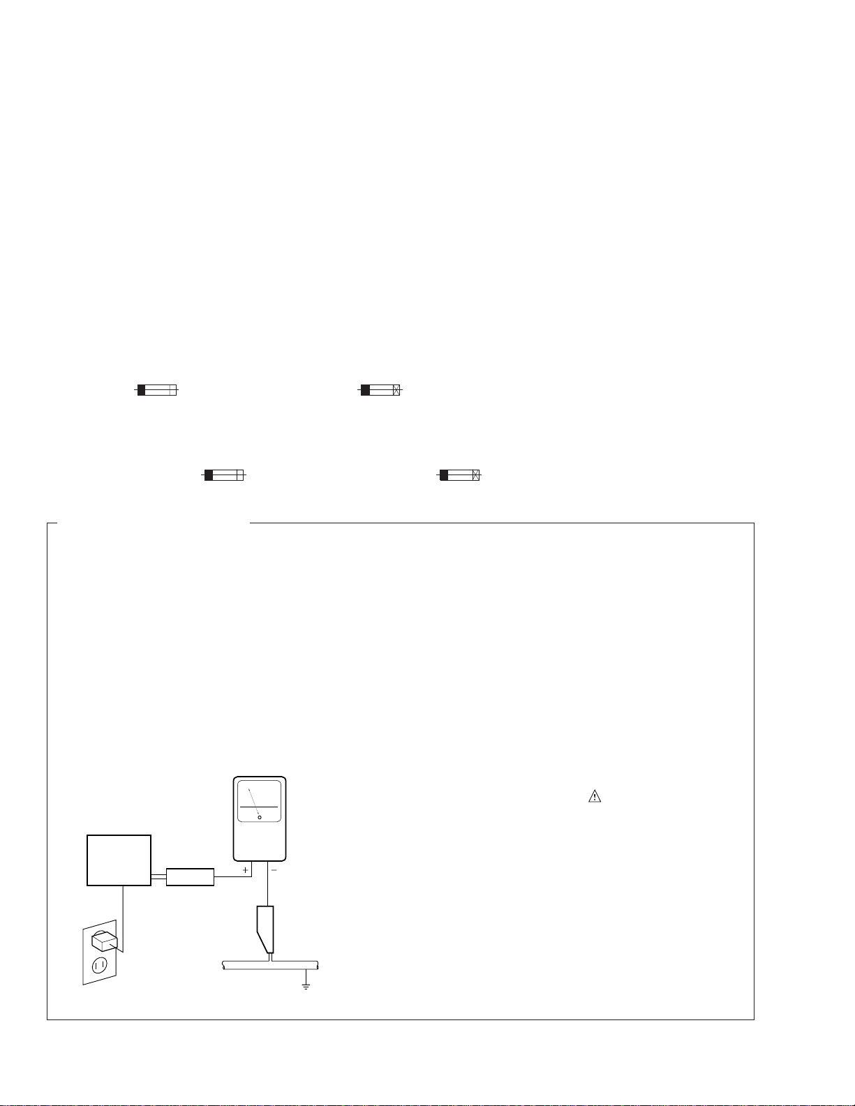
LEAKAGE CURRENT CHECK
Measure leakage current to a known earth ground
(water pipe, conduit, etc.) by connecting a leakage
current tester such as Simpson Model 229-2 or
equivalent between the earth ground and all exposed
metal parts of the appliance (input/output terminals,
screwheads, metal overlays, control shaft, etc.). Plug
the AC line cord of the appliance directly into a 120V
AC 60 Hz outlet and turn the AC power switch on. Any
current measured must not exceed 0.5 mA.
Reading should
not be above
0.5 mA
Earth ground
Device
under
test
Also test with plug
reversed
(Using AC adapter
plug as required)
Leakage
current
tester
Test all exposed
metal surfaces
AC Leakage Test
ANY MEASUREMENTS NOT WITHIN THE LIMITS
OUTLINED ABOVE ARE INDICATIVE OF A POTENTIAL SHOCK HAZARD AND MUST BE CORRECTED BEFORE RETURNING THE APPLIANCE
TO THE CUSTOMER.
2. PRODUCT SAFETY NOTICE
Many electrical and mechanical parts in the appliance have special safety related characteristics. These
are often not evident from visual inspection nor the
protection afforded by them necessarily can be obtained by using replacement components rated for
voltage, wattage , etc. Replacement parts which have
these special safety characteristics are identified in
this Service Manual.
Electrical components having such features are
identified by marking with a
on the parts list in this Service Manual.
The use of a substitute replacement component which
does not have the same safety characteristics as the
PIONEER recommended replacement one, shown in
the parts list in this Service Manual, may create shock,
fire, or other hazards.
Product Safety is continuously under review and
new instructions are issued from time to time. For
the latest information, always consult the current
PIONEER Service Manual. A subscription to, or additional copies of, PIONEER Service Manual may be
obtained at a nominal charge from PIONEER.
on the schematics and
2
Page 3
LITHIUM BATTERY NOTICE
M-F10
WARNING!
Lithium batteries. Danger of explosion. Replacement must be done by
qualified personnel and only by following the instructions given in the
service manual.
This warning is stated on the product or in the operating instructions.
When replacing the lithium batteries, follow the note below.
Dispose of the used battery promptly. Keep away from children. Do
not disassemble and do not dispose of in fire.
The battery used in this device may present a fire or chemical hazard
Lithiumbatteri − Eksplosionsfare ved
fejlagtig håndtering. Udskiftning må kun
ske med batteri af samme fabrikat og
type. Levér det brugte batteri tilbage til
leverandøren.
Denne advarsel or angivet på produktet eller i brugsvejledningen.
Ved udskiftning af lithium batterierne følges nedenstående
anveisning.
Batterierne må kun udskiftes med batterier af samme type og
mærke.
ADVARSEL!
if mistreated. Do not recharge, disassemble, heat above 100 ˚C or
incinerate. Replace only with the same Part Number. Use of another
battery may present a risk of fire or explosion.
Note: The lithium battery installation position is shown in the
exploded views.
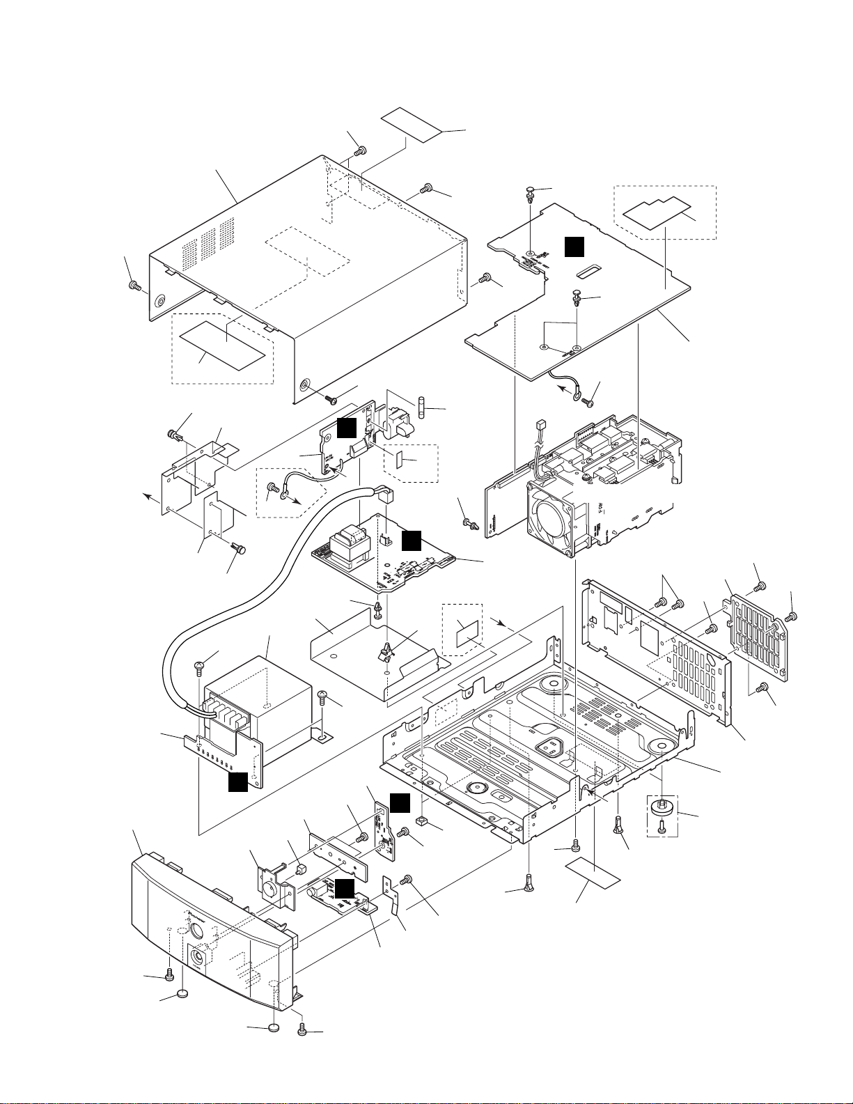
2. EXPLODED VIEWS AND PARTS LIST
NOTES : Parts marked by “ NSP ” are generally unavailable because they are not in our Master Spare Parts List.
The mark found on some component parts indicates the importance of the safety factor of the part.
Therefore, when replacing, be sure to use parts of identical designation.
Screw adjacent to mark on the product are used for disassembly.
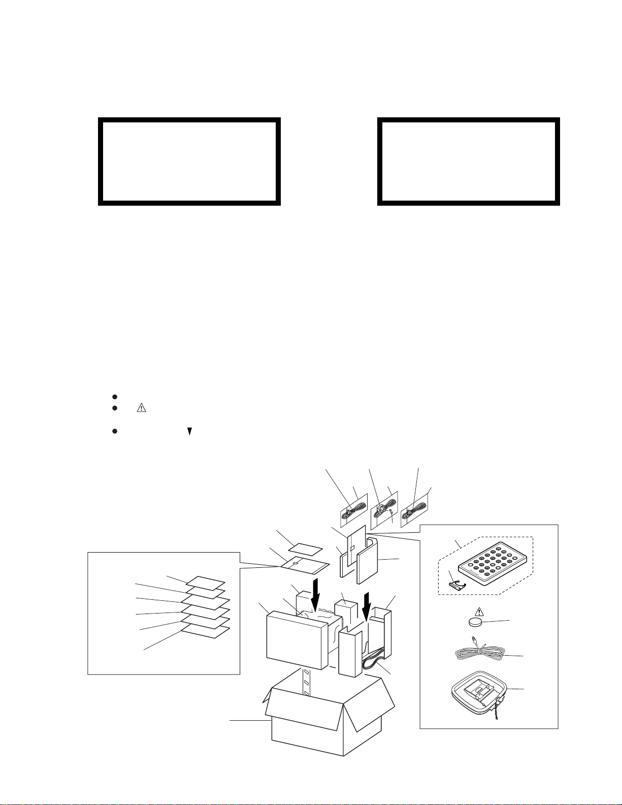
2.1 PACKING
(Except KUXJ/CA)
8
1
6
7
24
(NVXJ only)
25
(KUXJ/CA only)
22
19
18
9
20(1/2)
23
3
(MYXJ type)
18
15
20(2/2)
3
(NVXJ type)3(KUXJ/CA type)
17 17 17
4
14
13
21
2, 11
12
OPEN/CLOSE
CD CD-R
CD
VOLUME
TUNER
CD-R
DIRECT PLAY 3
AUX
1
SOUND
TAPEMD
¡
7
STANDBY/ON
4¢
TIMER
SET MENU
CANCEL
CD-R
SYSTEM
MENU
DISP
DISP
CHARA
16
5
10
3
Page 4
M-F10
(1) PACKING PARTS LIST
Mark No. Description Part No.
Mark No. Description Part No.
1 Paper Pattern AAX7807
2 System Cable (20P) ADE7057
3 AC Power Cord
4 Fuse (T5A)
5 FM Wire Antenna
See Contrast table (2)
See Contrast table (2)
See Contrast table (2)
NSP 16 Lithium Battery (CR2025) VEM1009
17 Vinyl Bag (115 × 270 × 0.05) Z21–013
NSP 18 Polyethylene Bag Z21–038
(0.03 × 230 × 340)
19 Front Pad A AHA7293
20 Rear Pad A AHA7294
6 Operating Instructions
7 Operating Instructions
8 Errata
NSP 9 Warranty Card
10 Loop Antenna ATB7009
See Contrast table (2)
See Contrast table (2)
See Contrast table (2)
See Contrast table (2)
21 Spacer A AHB7037
22 Packing Case
23 Sheet Z23–026
24 Operating Instructions
25 Operating Instructions
11 Ferrite Core ATX7007
12 Remote control Unit AXD7271
13 Battery Lid AZN7834
14 Stand A AXG7096
15 Stand B AXG7097
(2) CONTRAST TABLE
MYXJ, NVXJ and KUXJ/CA are constructed the same except for the following:
Mark
No.
Symbol and Description
MYXJ type NVXJ type KUXJ/CA type
3 AC Power Cord ADG1154 ADG1156 ADG7022
4 Fuse (T5A) Not used AEK7001 Not used
5 FM Wire Antenna ADH7005 ADH7005 ADH7004
6 Operating Instructions ARC7301 Not used Not used
(Dutch/Swedish/Spanish/Portuguese)
7 Operating Instructions ARE7264 Not used Not used
(English/French/German/Italian)
Part No.
See Contrast table (2)
See Contrast table (2)
See Contrast table (2)
Remarks
NSP 9 Warranty Card ARY7022 ARY7022 ARY7045
8 Errata ARX7037 ARX7037 Not used
22 Packing Case AHD7941 AHD7942 AHD7905
24 Operating Instructions (English) Not used ARB7227 Not used
25 Operating Instructions Not used Not used ARE7256
(English/French)
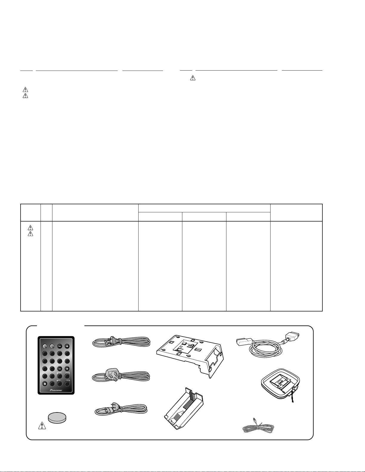
ACCESSORIES
OPEN/CLOSE
VOLUME
CD CD-R
AUX
CD
CD-R
17¡
STANDBY/ON
TUNER
DIRECT PLAY 3
SET MENU
CANCEL
SOUND
TAPEMD
TIMER
4¢
CD-R
DISP
SYSTEM
MENU
DISP
CHARA
Remote control unit
(AXD7271)
Lithium battery
(CR2025)
AC power cord
(ADG1154)
(For MYXJ type)
AC power cord
(ADG1156)
(For NVXJ type)
AC power cord
(ADG7022)
(For KUXJ/CA type)
Stand A
(AXG7096)
System cable (ADE7057)
AM loop antenna
(ATB7009)
FM wire antenna
(ADH7005: For MYXJ and NVXJ types)
(ADH7004: For KUXJ/CA type)
Stand B
(AXG7097)
4
Page 5
M-F10
A
B
A
C
B
C
27
30
29
30
30
16
16
4
30
30
30
8
16
19
34
24
17
7
32
6
26
12
30
30
30
15
28
23
9
31
31
31
13
31
10
15
14
30
25
14
11
31
22
31
31
Holder Unit
5
3
32
1
2
21
18
21
20
30
Refer to "2.3 HEAT SINK ASSY".
KUXJ/CA Only
KUXJ/CA
Only
KUXJ/CA
Only
KUXJ/CA
Only
KUXJ/CA Only
35
33
36
H
A
B
C
F
E
2.2 EXTERIOR
please order Caution Label (No.29) too
and paste it to the bonnet.
Note: when you order the bonnet (No.27),
5
Page 6

M-F10
(1) EXTERIOR SECTION PARTS LIST
Mark No. Description Part No.
Mark No. Description Part No.
1 AC IN Assy
2 PRIMARY Assy
3 SECONDRY Assy
4 COMPLEX Assy
5 LED Assy AWU7562
6 HP Assy AWU7563
7 Power Transformer (T1)
8 Fuse (FU1)
NSP 9 Chassis ANA7110
10 Rear Panel
11 Erath Plate ANG7331
12 Lens Bracket AAK7766
13 Rear Mold AAX7803
14 Leg AEB7090
NSP 15 PCB Holder AEC7057
NSP 16 PCB Spacer (3×6) AEC7156
17 Bottom Barrier AEC7283
18 Side Barrier AEC7285
NSP 19 PCB Spacer AEC7289
20 Sub Barrier AEC7312
21 Nylon Rivet AEC7315
22 Disc Guard PNM1245
23 Foot (Rubber) REC-434
NSP 24 Card Spacer REC1156
25 Front Panel AMB7702
See Contrast table (2)
See Contrast table (2)
See Contrast table (2)
See Contrast table (2)
See Contrast table (2)
See Contrast table (2)
See Contrast table (2)
26 LED Lens PNW2019
27 Bonnet AZN7837
NSP 28 Label
29 Caution Label
30 Screw BBZ30P080FNI
31 Screw BPZ30P100FZK
32 Screw FBT40P060FCC
33 65 Label
NSP 34 Fuse Caution
NSP 35 Fuse Caution B
NSP 36 Fuse Card
See Contrast table (2)
See Contrast table (2)
See Contrast table (2)
See Contrast table (2)
See Contrast table (2)
See Contrast table (2)
(2) CONTRAST TABLE
MYXJ, NVXJ and KUXJ/CA are constructed the same except for the following:
Mark
No.
1 AC IN Assy AWU7556 AWU7556 AWU7609
2 PRIMARY Assy AWU7557 AWU7557 AWU7658
3 SECONDRY Assy AWU7558 AWU7558 AWU7614
4 COMPLEX Assy AWU7559 AWU7559 AWU7616
7 Power Transformer (T1) ATS7278 ATS7278 ATS7279
8 Fuse (FU1) REK1025 REK1025 REK1066
10 Rear Panel ANC7935 ANC7935 ANC7967
NSP 28 Label ARW7101 ARW7107 ARW7103
29 Caution Label ARW7112 ARW7112 ARW7113
33 65 Label Not used Not used ARW7050
NSP 34 Fuse Caution Not used Not used AAX7817
NSP 35 Fuse Caution B Not used Not used AAX7833
NSP 36 Caution Card Not used Not used AAX2343
Symbol and Description
MYXJ type NVXJ type KUXJ/CA type
(T2AL250V) (T2AL250V) (4A/125V)
6
Part No.
Remarks
Page 7
M-F10
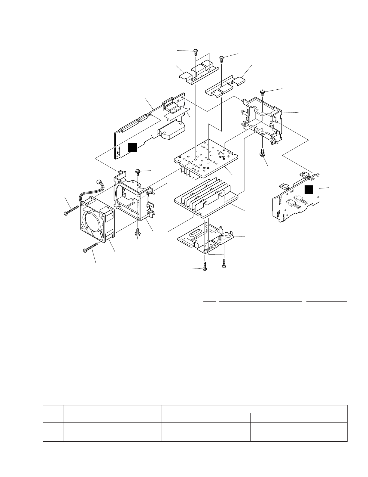
2.3 HEAT SINK ASSY
12
G
10
5
1
7
9
10
5
9
8
9
6
D
6
2
12
8
9
3
11
4
11
(1) HEAT SINK ASSY SECTION PARTS LIST
Mark No. Description Part No.
1 AMP Assy AWU7560
2 REG Assy AWU7561
3 DC Fan Motor AXM7014
4 Power Pac Holder ANG7109
5 Heat Plate ANG7328
6 Heat Sink ANH7132
7 Mica Sheet AEE7036
8 Fan Mold AMR7321
9 Screw ABA1021
10 Screw BBZ30P080FNI
Mark No. Description Part No.
11 Screw BBZ30P160FMC
12 Screw BPZ30P350FZK
(2) CONTRAST TABLE
MYXJ, NVXJ and KUXJ/CA are constructed the same except for the following:
Symbol and DescriptionNo.Mark
MYXJ type NVXJ type KUXJ/CA type
Part No.
Remarks
1 AMP Assy AWU7560 AWU7560 AWU7618
2 REG Assy AWU7561 AWU7561 AWU7619
7
Page 8
1
234
M-F10
3. BLOCK DIAGRAM AND SCHEMATIC DIAGRAM
Note: When ordering service parts, be sure to refer to "EXPLODED VIEWS AND PARTS LIST" or "PCB PARTS LIST".
3.1 BLOCK DIAGRAM and OVERALL CONNECTION DIAGRAM
A
: AUDIO SIGNAL ROUTE
PRIMARY ASSY
(AWU7557: MYXJ, NVXJ types)
B
(AWU7658: KUXJ/CA type)
IC41
T1 POWER TRANSFORMER
B
H
COMPLEX ASSY
(AWU7559: MYXJ, NVXJ types)
(AWU7616: KUXJ/CA type)
D3001
D11
D21
C
SECONDRY ASSY
LIVE
NEUTRAL
(AWU7558: MYXJ, NVXJ types)
(AWU7614: KUXJ/CA type)
C
A
AC IN ASSY
(AWU7556:
MYXJ, NVXJ types)
(AWU7609:
KUXJ/CA type)
G
AMP ASSY
(AWU7560: MYXJ, NVXJ types)
(AWU7618: KUXJ/CA type)
F
LED ASSY
(AWU7562)
(HP)(HP)
(HP)
D
AC POWER
CORD
8
1234
E
HP ASSY
(AWU7563)
(HP)
Page 9
5
67
8
M-F10
IC31
REG ASSY
(AWU7561: MYXJ, NVXJ types)
D
(AWU7619: KUXJ/CA type)
The power supply is shown
with the marked box.
(C)
AKE1025 (MYXJ, NVXJ)
AKE7065 (KUXJ/CA)
(C)
A
B
65
BALANCED
7
BUFFER
2
IC3021
7
(C)
(C)
3
LPF
16
2
(C)
(C)
7
(C)
14
(C)
C
To STEREO CD TUNER XC-F10
17
5
7
D
(HP)(HP)
9
5
6
7
8
Page 10

1
234
M-F10
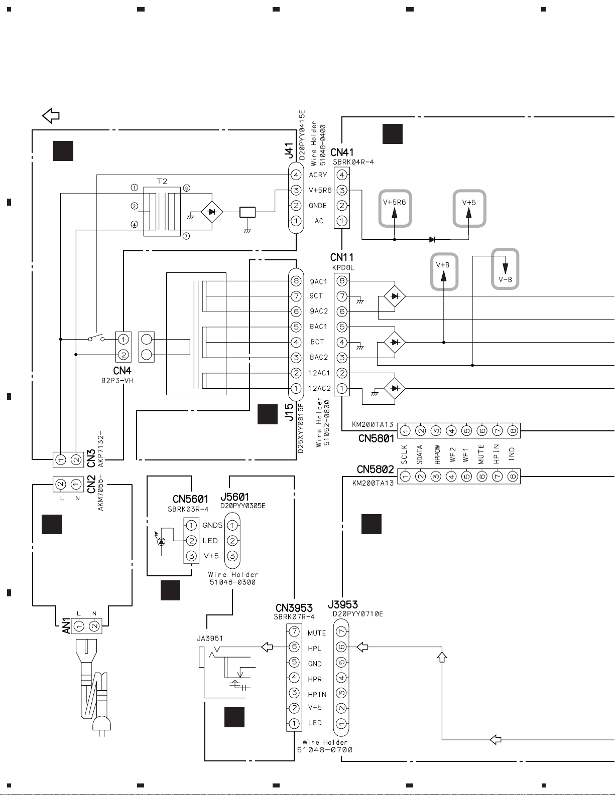
3.2 AC IN, PRIMARY and SECONDRY ASSYS
A
CAUTION : FOR CONTINUED PROTECTION AGAINST RISK OF FIRE.
REPLACE WITH SAME TYPE NO. 491010 MFD. BY
LITTELFUSE INC. FOR IC11 and IC12 (AEK7022).
SECONDRY ASSY
C
(AWU7558: MYXJ, NVXJ types)
(AWU7614: KUXJ/CA type)
CAUTION : FOR CONTINUED PROTECTION AGAINST RISK OF FIRE.
REPLACE WITH SAME TYPE NO. 491007 MFD. BY
LITTELFUSE INC. FOR IC13 and IC14 (AEK7021).
CAUTION : FOR CONTINUED PROTECTION AGAINST RISK OF FIRE.
REPLACE WITH SAME TYPE NO. 49102.5 MFD. BY
LITTELFUSE INC. FOR IC15 (AEK7014).
B
T1 POWER TRANSFORMER
ATS7278: MYXJ, NVXJ
ATS7279: KUXJ/CA
230V:
MYXJ, NVXJ
120V:
KUXJ/CA
J15
H
CN11
PRIMARY ASSY
(AWU7557:
MYXJ, NVXJ types)
(AWU7658:
B
KUXJ/CA type)
T2:
ATT7050
: MYXJ, NVXJ
ATT7049
: KUXJ/CA
CN4
+12V +5.6V
H
CN41
2200/16:
MYXJ, NVXJ
C
CN3
1000/16:
KUXJ/CA
J41
CN2
A
AC IN ASSY
(AWU7556:
MYXJ, NVXJ types)
(AWU7609:
KUXJ/CA type)
KUXJ/CA only
D
(T2A) REK1025: MYXJ, NVXJ
(4A) REK1066: KUCJ/CA
MYXJ, NVXJ only
AN1
BKP1046:
MYXJ, NVXJ
AKP7032:
KUXJ/CA
AN1
NOTE FOR FUSE REPLACEMENT
CAUTION: FOR CONTINUED PROTECTION
AGAINST RISK OF FIRE.
REPLACE ONLY WITH SAME
TIME AND RATINGS ONLY.
AC220–230V 50/60Hz: MYXJ
AC230V 50/60Hz: NVXJ
AC120V 60Hz: KUXJ/CA
AC POWER CORD
ADG1154: MYXJ
ADG1156: NVXJ
ADG7022: KUXJ/CA
10
A
B
1234
C
Page 11

1
3.3 REG, HP and LED ASSYS
23
4
M-F10
H
CN52
REG ASSY
D
(AWU7561: MYXJ, NVXJ types)
(AWU7619: KUXJ/CA type)
–18V
+21V
A
+18V
33/50
2.2k
33/50
0
B
G
J3953
CN51
CN3953
(HP)
6.8k
3.9k
1k
MTZJ6.8B
(HP) (HP)
V+5
(MYXJ, NVXJ)
V+12
(KUXJ/CA)
CN5601
F
LED ASSY
(AWU7562)
270: MYXJ, NVXJ
1k: KUXJ/CA
33/50
C
V+5
(MYXJ, NVXJ)
V+12
(KUXJ/CA)
D
HP ASSY
E
(AWU7563)
D
1
2
3
E
F
4
11
Page 12

1
234
M-F10
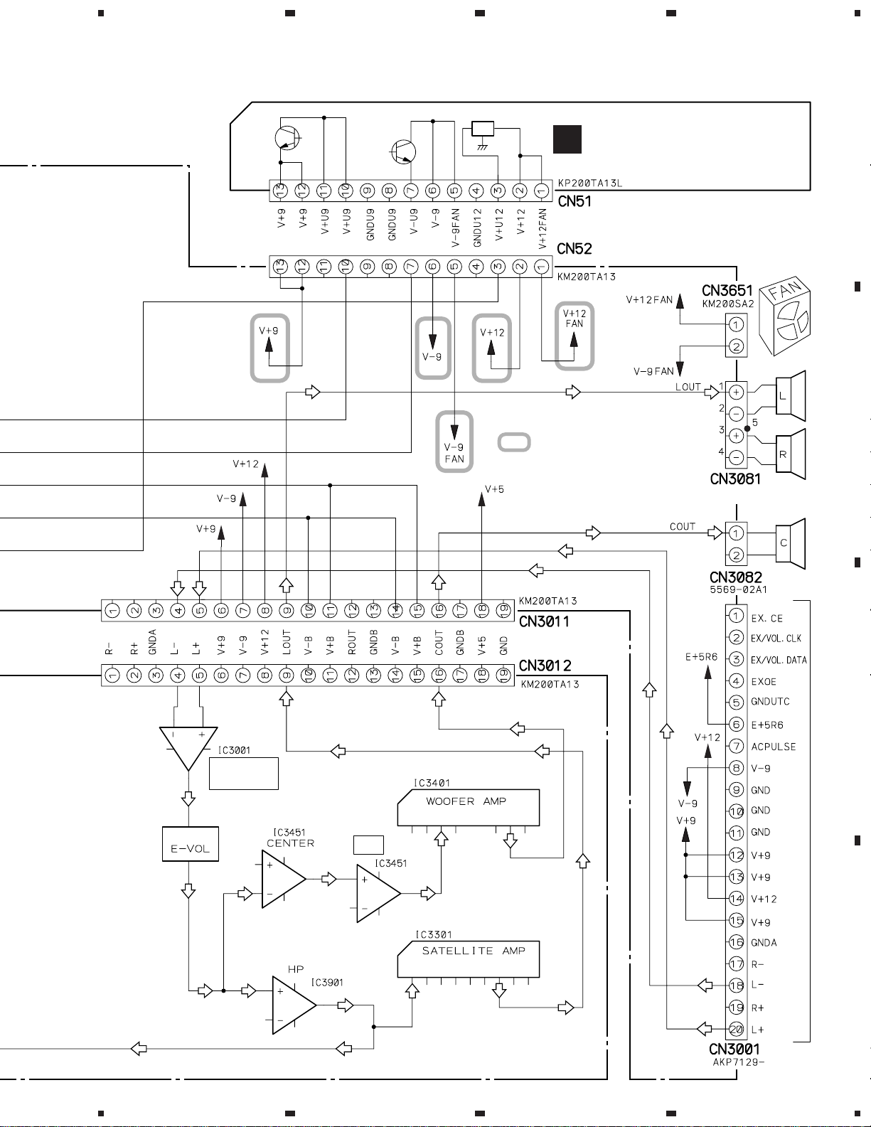
3.4 AMP and COMPLEX ASSYS
A
SIGNAL ROUTE
: AUDIO SIGNAL
(C)
: AUDIO SIGNAL (CENTER)
(HP)
: AUDIO SIGNAL (HEADPHONE)
BALANCED BUFFER
5V
8.8V
CN3012
B
–8.8V
(HP) (HP)
(HP)
–8.8V
C
D
AMP ASSY
(AWU7560: MYXJ, NVXJ types)
(AWU7618: KUXJ/CA type)
8.8V
G
(C)
28V
MYXJ,
NVXJ
Only
330330
–28V
–28V
(HP)
CN5802
0
R5699
(C)
(C)
(C)
28V
(C)
For
MYXJ,
NVXJ
For XUXJ/CA
J3953
(HP)
V+5
V+12
V+5:
MYXJ, NVXJ
V+12:
KUXJ/CA
CN3953
E
12
G
1234
Page 13

5
67
8
M-F10
CN11
J15
C
CN3011
KUXJ/CA
Only
5A
491005
(AKE7019)
D
CN51
CAUTION : FOR CONTINUED PROTECTION AGAINST RISK OF FIRE.
REPLACE WITH SAME TYPE NO. 491005 MFD. BY
LITTELFUSE INC. FOR IC53 (AEK7019).
J41
CN52
B
The power supply is shown
with the marked box.
D3001
CN41
1SS133-T: MYXJ, NVXJ
1SS355-T: KUXJ/CA
L3021:
KUXJ/CA Only
CN3001
A
B
To STEREO CD TUNER XC-F10
(C) (C)
CN5801
CN3651
5V
CN3801
AKE1025
(MYXJ, NVXJ)
AKE7065
(KUXJ/CA)
(C)
∗
L3081–L3083: ATH–059 (MYXJ, NVXJ)
R3081–R3083: 100 (MYXJ, NVXJ)
(C)
ATH–133 (KUXJ/CA)
10 (KUXJ/CA)
(C)
CN3802
C
To FAN MOTOR
5
D
COMPLEX ASSY
(AWU7559: MYXJ, NVXJ types)
H
(AWU7616: KUXJ/CA type)
H
6
7
8
13
Page 14

1
234
M-F10
4. PCB CONNECTION DIAGRAM
NOTE FOR PCB DIAGRAMS:
1. Part numbers in PCB diagrams match those in the schematic
diagrams.
A
2. A comparison between the main parts of PCB and schematic
diagrams is shown below.
Symbol in PCB
Diagrams
BCE
BCE
DGS
Symbol in Schematic
Diagrams
BCE
BCE
BCEBCE
DGSDGS
Part Name
Transistor
Transistor
with resistor
Field effect
transistor
Symbol in PCB
Diagrams
3. The parts mounted on this PCB include all necessary parts
for several destination.
For further information for respective destinations, be sure
to check with the schematic diagram.
4. Viewpoint of PCB diagrams
P. C. Board Chip Part
4.1 AC IN, PRIMARY and SECONDRY ASSYS
B
SIDE A
POWER
TRANSFORMER
Symbol in Schematic
Diagrams
CapacitorConnector
PRIMARY ASSY
B
Part Name
Resistor array
3-terminal
regulator
SIDE A
SIDE B
H
CN41
IC41
C
C
SECONDRY ASSY
D
14
A
IC12
IC15
IC11
IC13
IC14
(ANP7345–C)
(ANP7345–C)
H
CN11
NEUTRAL
LIVE
AC POWER CRD
A
AC IN ASSY
(ANP7345–C)
B
1234
C
Page 15

1
PRIMARY ASSY
B
C
SECONDRY ASSY
AC IN ASSY
A
Q42
Q41
(ANP7345–C)
(ANP7345–C)
(ANP7345–C)
23
4
M-F10
A
SIDE B
B
C
D
A
1
2
3
B
C
4
15
Page 16

1
234
M-F10
4.2 COMPLEX, AMP, REG, HP and LED ASSYS
SIDE A
A
D
REG ASSY
IC31
Q54
Q52
Q51
Q55
B
H
COMPLEX ASSY
Q57
Q53
IC53
(ANP7345–C)
C
Front
IC54
D
(ANP7345–C)
C
J15
16
D
H
1234
Page 17

5
67
8
M-F10
SIDE A
A
G
AMP ASSY
IC3401
IC3301
B
F
LED ASSY
To FAN MOTOR
B
J41
E
IC3411
C
(ANP7345–C)
HP ASSY
(ANP7345–C)
5
D
(ANP7345–C)
E H
6
7
F
G
8
17
Page 18

M-F10
(
)
1
234
SIDE B
A
G
AMP ASSY
Q3471
|
Q3474
Q3402
Q3312
Q3401
IC3401
B
Q3311
Q3313
IC3451
Q5803
Q5804
IC5801
Q3659
Q5802
Q43
H
COMPLEX ASSY
IC3901
IC3021
C
Q3023
Q3024
IC3001
E
(ANP7345–C)
D
HP ASSY
Q3953
Q3951
Front
Q3952
F
LED ASSY
18
E H
F
1234
G
(ANP7345–C)
ANP7345–C
Page 19

5
67
8
M-F10
SIDE B
A
Q3603
Q3602
Q3604
|
Q3607
Q3654
Q3651
Q3652
D
REG ASSY
IC51
B
(ANP7345–C)
Q3653
Q5601
(ANP7345–C)
C
Front
D
D
5
6
7
H
8
19
Page 20

M-F10
5. PCB PARTS LIST
NOTES : ÷ Parts marked by “ NSP ” are generally unavailable because they are not in our Master Spare Parts List.
÷ The
÷ When ordering resistors, first convert resistance values into code form as shown in the following examples.
LIST OF WHOLE PCB ASSEMBLIES
mark found on some component parts indicates the importance of the safety factor of the part.
Therefore, when replacing, be sure to use parts of identical designation.
Ex. 1 When there are 2 effective digits (any digit apart from 0), such as 560 ohm and 47k ohm (tolerance is shown by
J = 5%, and K = 10%).
560 Ω = 56 × 10
47k Ω = 47 × 10
0.5 Ω = R50 ...................................................................... RN2H Â 5 0 K
1 Ω = 1R0 ......................................................................... RS1P 1 Â 0 K
Ex. 2 When there are 3 effective digits (such as in high precision metal film resistors).
5.62k Ω = 562 × 10
1
= 561................................................... RD1/4PU 5 6 1 J
3
= 473 .................................................. RD1/4PU 4 7 3 J
1
= 5621 ........................................... RN1/4PC 5 6 2 1 F
Mark
NSP AMP MAIN Assy AWM7499 AWM7499 AWM7524
∗1: Although AWU7558 and AWU7614 are different in part number, they have same service parts.
∗2: Although AWU7561 and AWU7619 are different in part number, they have same service parts.
Symbol and Description
MYXJ type NVXJ type KUXJ/CA type
AC IN Assy AWU7556 AWU7556 AWU7609
PRIMARY Assy AWU7557 AWU7557 AWU7658
SECONDRY Assy AWU7558 AWU7558 AWU7614 ∗1
COMPLEX Assy AWU7559 AWU7559 AWU7616
AMP Assy AWU7560 AWU7560 AWU7618
REG Assy AWU7561 AWU7561 AWU7619 ∗2
LED Assy AWU7562 AWU7562 AWU7562
HP Assy AWU7563 AWU7563 AWU7563
Part No.
CONTRAST OF PCB ASSEMBLIES
AC IN Assy
A
AWU7556 and AWU7609 are constructed the same except for the following:
Mark
Symbol and Description
AWU7556 AWU7609
L1 ATF–151 Not used
C2 (0.01µF/275V) ACE7013 Not used
R1 Not used RCN1080
AN1 AC Inlet 1P BKP1046 AKP7032
Part No.
Remarks
Remarks
PRIMARY Assy
B
AWU7557 and AWU7658 are constructed the same except for the following:
Mark
Symbol and Description
AWU7557 AWU7658
T2 ATT7050 ATT7049
C42 CEAT222M16 CEAT102M16 ∗
Part No.
∗: As for the AWU7557, the design change is done like the AWU7658.
20
Remarks
Page 21

AMP Assy
G
AWU7560 and AWU7618 are constructed the same except for the following:
M-F10
Mark
Symbol and Description
AWU7560 AWU7618
L3021 LAU560J Not used ∗
Part No.
∗: As for the AWU7560, the design change is done like the AWU7618.
COMPLEX Assy
H
AWU7559 and AWU7616 are constructed the same except for the following:
Mark
AWU7559 AWU7616
IC53 (5A/125V) Not used AKE7019
D3001 1SS133 1SS355 ∗
L3021 Not used LAU560J ∗
L3801–L3803 ATH–059 ATH–133
R3801–R3803 RD1/4LMF101J RD1/4LMF100J
R5699 Not used RS1/10S0R0J ∗
CN3801 AKE1025 AKE7065
Part No.
∗: As for the AWU7559, the design change is done like the AWU7616.
Remarks
RemarksSymbol and Description
PCB PARTS LIST FOR MYXJ TYPE
Mark No. Description Part No.
AC IN ASSY
A
COILS AND FILTERS
L1 ATF–151
CAPACITORS
C2 (0.01µF/275V) ACE7013
OTHERS
CN2 PLUG 4P AKM7055
H101, H102 FUSE CLIP AKR7001
AN1 AC INLET 1P BKP1046
PRIMARY ASSY
B
SEMICONDUCTORS
IC41 NJM78M56FA
Q41 2SC2412K
Q42 DTA124EK
D42, D44 1SS355
D41 S1WB(A)60SD
TRANSFORMER
T2 ATT7050
Mark No. Description Part No.
RELAY
RY1 ASR7018
CAPACITORS
C1, C3 (0.01µF/275V) ACE7013
C44 CEAT101M10
C42 CEAT222M16
C41 CQMBA473J50
RESISTORS
All Resistors RS1/10S J
OTHERS
41 4P CABLE HOLDER 51048–0400
CN3 SOCKET 4P AKP7132
CN4 2P-VH CONNECTOR B2P3–VH
J41 4P JUMPER WIRE D20PYY0415E
SECONDRY ASSY
C
SEMICONDUCTORS
IC15 (2.5A/125V) AEK7014
IC13, IC14 (7A/125V) AEK7021
IC11, IC12 (10A/125V) AEK7022
21
Page 22

M-F10
Mark No. Description Part No. Mark No. Description Part No.
OTHERS
15 8P CABLE HOLDER 51052–0800
J15 JUMPER WIRE D25XYY0815E
COMPLEX ASSY
H
SEMICONDUCTORS
IC5801 BU4094BCF
Q3601–Q3603 2SA1037K
Q3604–Q3606 2SC2412K
Q3607, Q3652 2SD2114K
Q3651, Q5802, Q5804 DTA124EK
Q3653 DTA124TK
Q3654, Q3659, Q43 DTC124EK
Q5601, Q5803 DTC143EK
D3001, D3604 1SS133
D3081, D3601–D3603, D3651–D3653 1SS355
D3655–D3658 1SS355
D11, D21 D3SBA20(B)
D32 S1WB(A)60SD
D3654 S5688G
COILS AND FILTERS
L3081–L3083 (5.3µH) ATH–059
SWITCHES AND RELAYS
RY3081, RY3082 ASR7007
CAPACITORS
C13 (18000µF/25V) ACH7099
C5802, C5803, C5805 CCSQCH221J50
C3602 CEAT100M50
C3659 CEAT101M10
C3651 CEAT101M16
C3601 CEAT221M6R3
C36 CEAT222M25
C3652 CEAT470M25
C14 CEAT682M25
C3087, C3089, C3091, C3093–C3095 CKSQYB102K50
C3088, C3090, C3092 CKSQYB103K50
C5801 CKSQYB472K50
C3331–C3333, C3338 CKSQYB473K50
C5804 CKSQYF104Z25
C3081–C3086 CKSQYF473Z50
C21, C22 CQMA223K2E
C11, C12, C37 CQMBA473J50
C23, C24 (4700µ/35V) RCH1107
RESISTORS
R3601–R3603 (0.1Ω, 1W) ACN7100
R3081–R3083 RD1/4LMF101J
R3617, R5821, R5822 RD1/4PU103J
R5807 RD1/4PU1R0J
R5806 RD1/4PU222J
R5808 RD1/4PU223J
R3699 RD1/4PU330J
R5823 RD1/4PU472J
Other Resistors RS1/10S J
OTHERS
CN3082 2P CONNECTOR 5569–02A1
3081 SPEAKER TERMINAL 4-P AKE1025
CN3001 20P SOCKET AKP7129
CN52 13P PLUG KM200TA13
CN3011 19P PLUG KM200TA19
CN5801 8P PLUG KM200TA8
CN11 L-CONNECTOR (8P) KPD8L
3082 SCREW PLATE VNE1948
AMP ASSY
G
SEMICONDUCTORS
IC3001, IC3451, IC3901 BA4558F–HT
IC3021 M62421FP
IC3301 STK402–040
IC3401 TDA7294V
Q3023, Q3024 2SC2412K
Q3311, Q3312, Q3401, Q3471, Q3472 2SD2114K
Q3313, Q3402, Q3473, Q3474 DTA124EK
D3021 UDZS10B
COILS AND FILTERS
L3021 LAU560J
CAPACITORS
C3321, C3322 CCSQCH221J50
C3025, C3027 CCSQCH470J50
C3317, C3318 CCSQCJ3R0C50
C3315, C3316 CCSQSL471J50
C3313, C3314 CEANP4R7M50
C3038, C3041, C3471 CEAT100M50
C3007, C3008, C3043, C3913 CEAT101M10
C3303, C3304 CEAT101M35
C3405, C3410, C3411 CEAT220M50
C3037 CEAT221M6R3
C3301, C3302, C3403 CEAT330M50
C3021, C3022 CEAT3R3M50
C3451 CEAT470M16
C3401 CEAT4R7M50
C3311, C3312 CECAR47M50
C3914 CEJQ101M10
C3319, C3320 CEJQ330M10
C3903, C3904 CEJQ470M16
C3402 CKSQYB102K50
C3005, C3006, C3028, C3036, C3039 CKSQYB103K50
C3305, C3309, C3310, C3334, C3404 CKSQYB103K50
C3406, C3407, C3461, C3462 CKSQYB103K50
C3033, C3034 CKSQYB223K25
C3029, C3030 CKSQYB333K25
C3452 CKSQYB333K50
22
Page 23

M-F10
Mark No. Description Part No. Mark No. Description Part No.
C3412, C3413 CKSQYB473K50
C3031, C3032 CKSQYB474K16
C3023, C3911, C3912 CKSQYF104Z25
C3026, C3901, C3902 CKSQYF105Z16
C3408, C3409 CKSQYF473Z50
LED ASSY
F
SEMICONDUCTORS
D5601 SLR–343VC
C3453 CQMBA683J50
RESISTORS
R3301, R3302 RD1/4LMF101J
R3317, R3318, R3405 RD1/4PU563J
R3009, R3010 RD1/4PU820J
R3001–R3008 RS1/10S1202F
Other Resistors RS1/10S J
OTHERS
3953 7P CABLE HOLDER 51048–0700
J3953 JUMPER WIRE D20PYY0710E
CN3012 19P SOCKET KP200TA19L
CN5802 8P SOCKET KP200TA8L
REG ASSY
D
SEMICONDUCTORS
IC51 BA4558F–HT
IC31 NJM7812FA
Q54 2SA933S
Q53 2SB1237X
Q55 2SC1740S
Q51, Q52 2SD2395
Q57 2SD2395
D53, D54 1SS355
D35 MTZJ6.8B
D55, D56 UDZS5.1B
RESISTORS
All Resistors RS1/10S J
HP ASSY
E
SEMICONDUCTORS
Q3951, Q3952 2SD2114K
Q3953 DTA124EK
CAPACITORS
C3951–C3954 CKSQYB103K50
C5601 CKSQYF104Z25
C5602 CKSQYF105Z16
RESISTORS
All Resistors RS1/10S J
OTHERS
5602 3P CABLE HOLDER 51048–0300
JA3951 JACK AKN7013
J5601 3P JUMPER WIRE D20PYY0305E
KN3951 EARTH METAL FITTING VNF1084
CAPACITORS
C34 CEAT100M50
C51, C57, C58 CEAT330M50
C53 CKSQYB103K50
C56 CKSQYB104K16
C35, C54 CKSQYB473K25
C55 CKSQYB474K16
RESISTORS
R61 RFA1/4PS100J
R65 RFA1/4PS151J
R81, R83 RS1LMFR22J
Other Resistors RS1/10S J
OTHERS
CN51 13P SOCKET KP200TA13L
6. ADJUSTMENT
There is no information to be shown in this chapter.
23
Page 24

M-F10
7. GENERAL INFOMATION
7.1 DIAGNOSIS
7.1.1 DISASSEMBLY
1
Remove the Bonnet Case.
COMPLEX Assy
3
2
20–30 degrees
apporox.
5
6
Remove the Front Panel.
7
9
8
Disconnect
the CN3953
4
Remove the Rear panel.
24
10
Page 25

7.1.2 SINGLE OPERATION METHOD
Voltage of each part and method of diagnosing each IC
Test Point for Service
M-F10
COMPLEX ASSYCOMPLEX ASSY
SIDE B
Diagnosis of Voltage of Each Part
FOR SERVICE 1. AC RY
1
in the power supply outlet.
Short
point of the COMPLEX Assy is short-circuited (AC RELAY ON), and the AC power code is inserted
2 The voltage of each part is checked.
Refer to next page (diagnosis point).
Diagnosis of Each IC
FOR SERVICE
1. AC RY
FOR SERVICE
3. MUTE
FOR SERVICE
2. SP RY
FOR SERVICE 1. AC RY
1
in the power supply outlet.
FOR SERVICE 2. SPRY
2
FOR SERVICE 3. MUTE
3
Short
point of the COMPLEX Assy is short-circuited (AC RELAY ON), and the AC power code is inserted
point of the COMPLEX Assy is short-circuited (SP RELAY ON).
point of the COMPLEX Assy is short-circuited (MUTE OFF).
Short
4 The AUDIO signal (About 1kHz) is input to the input side of each IC, and the output is confirmed.
Refer to next page (diagnosis point).
OP amplifier (AMP Assy) . . . . . . IC3001, IC3901, and IC3451
Amplifier (AMP Assy) . . . . . . IC3301 and IC3401
Diagnosis of IC3021
Note: The single operation confirmation cannot be done, because IC3021(E-VOL) is
controlled with the microcomputer of Stereo CD tuner (XC-F10).
Short
25
Page 26

M-F10
Diagnosis Points
H
COMPLEX ASSY
FRONT
R–
GNDA
L–
1
OUT
G
AMP ASSY
1
IN
ROUT
LOUT
For IC3001 confirmation
1
2
For IC3901 confirmation
3
For IC3301 confirmation
4
For IC3451 confirmation
5
For IC3401 confirmation
SIDE B
SPEAKER TERMINAL
Voltage Measurement Points
4
SIDE B
3
OUT
4
5
OUT
OUT
5
IN
IN
C IN
GNDA
GNDA
C IN
R IN
L IN
GNDA
R IN
GNDA
2
IN
2
OUT
3
L IN
IN
26
Page 27

7.2 IC
M62421FP (IC3021: AMP ASSY)
Digital Sound Controller built-in Tone Control
Pin Assignment (Top View) Block Diagram
M-F10
¶ The information shown in the list is basic information and may not
correspond exactly to that shown in the schematic diagrams.
Pin Function
No. Name I/O Description
1 REF I Standard voltage input terminal
2 CH1IN I Signal input terminal for channel 1
3 SIMIN1 I
4
SIMOUT1
5 BASS1 I
6 TRE1 I Capacitor installation terminal for Treble
7 OUT1 O
8 DGND –– Ground terminal for digital circuit
9 DAT I Input/Output terminal for control data
10 CLK I Clock input terminal for serial data transfer
Capacitor installation terminal for Simulated inductor 1
O
Capacitor installation terminal for Bass adjustment
of channel 1 side
adjustment of channel 1 side
Signal output terminal after volume is controlled of
channel 1 side
No. Name I/O Description
11 CS I Chip select signal terminal
12 DVDD –– Power supply terminal for digital circuit
13 AGND –– Ground terminal for analog circuit
14 OUT2 O
15 TRE2 I Capacitor installation terminal for Treble
16 BASS2 I
17
SIMOUT2
18 SIMIN2 I
19 CH2IN I Signal input terminal for channel 2
20 AVDD –– Power supply terminal for analog circuit
Signal output terminal after volume is controlled of
channel 2 side
adjustment of channel 2 side
Capacitor installation terminal for Bass adjustment
of channel 2 side
O
Capacitor installation terminal for Simulated inductor 2
27
Page 28

M-F10
8. PANEL FACILITIES AND SPECIFICATIONS
8.1 PANEL FACILITIES
1 Power indicator – lights when the system is on
2 Headphone jack – plug in a pair of headphones for private
listening (the sound from the speakers is muted when headphones are plugged in)
1
For KUXJ/CA Type
Output for Satellite Speakers
Continuous average power output of 20 watts*
per channel, min., at 8 ohms, from 200 Hz to
20,000 Hz with no more than 0.9 %** total
harmonic distortion.
Output for Subwoofer Speaker
Continuous average power output of 30 watts*
min., at 4 ohms, from 40 Hz to 200 Hz with no
more than 0.9 %** total harmonic distortion.
* Measured pursuant to the Federal Trade Commission’s
Trade Regulation rule on Power Output Claims for
Amplifiers.
** Measured by Audio Spectrum Analyzer.
2
8.2 SPECIFICATIONS
For MYXJ Type
Continuous Power Satellite (RMS) ............................ 30 W + 30 W
(3 kHz, THD 10%, 8 Ω)
Continuous Power Subwoofer (RMS) ...................................... 50 W
(70 Hz, THD 10%, 4 Ω)
Continuous Power Satellite (DIN)...............................23 W + 23 W
(3 kHz, THD 1%, 8 Ω)
Continuous Power Subwoofer (DIN)........................................ 43 W
(70 Hz, THD 1%, 4 Ω)
Power Requirements ................................... AC 220-230 V, 50/60 Hz
Power Consumption (ON mode) ............................................127 W
Power Consumption (Standby mode) .....................................0.9 W
Dimensions................................. 190 (W) × 80 (H) × 267 (D) mm
Weight...................................................................................... 4.0 kg
• Above specifications are for when the power supply is 230 V.
For NVXJ Type
Continuous Power (RMS)
Satellite ................................ 30 W + 30 W (3 kHz, THD 10%, 8 W)
Subwoofer ......................................... 50 W (70 Hz, THD 10%, 4 W)
Continuous Power (DIN)
Satellite .................................. 23 W + 23 W (3 kHz, THD 1%, 8 W)
Subwoofer ............................................43 W (70 Hz, THD 1%, 4 W)
Continuous Power Satellite (RMS) ............................ 30 W + 30 W
(3 kHz, THD 10%, 8 Ω)
Continuous Power Subwoofer (RMS) ...................................... 50 W
(70 Hz, THD 10%, 4 Ω)
Power Requirements ................................................ AC 120 V, 60 Hz
Power Consumption (ON mode) ............................... 125 W, 160 VA
Power Consumption (Standby mode) .....................................0.9 W
Dimensions................................. 190 (W) × 80 (H) × 267 (D) mm
(7 1/2(W) x 3 1/8(H) x 10 1/2(D) in.)
Weight................................................................4.0 kg (8 lb. 13 oz.)
Accessories
Remote control unit ........................................................................1
Stand A............................................................................................. 1
Stand B ............................................................................................ 1
Paper pattern ................................................................................... 1
System cable .................................................................................... 1
FM wire antenna ............................................................................ 1
AM loop antenna ............................................................................. 1
Lithium battery (CR2025) .............................................................. 1
AC power cord .................................................................................. 1
Operating instructions .................................................................... 1
Warranty card.................................................................................. 1
NOTE: Specifications and design subject to possible
modification without notice, due to improvements.
Power Requirements ......................... AC 230 V, 50/60 Hz
....................................................AC 240 V, 50/60 Hz
Power Consumption (ON mode) .......................... 127 W
........................................................................ 110 W
(UK model)
(Non-UK model)
(UK model)
(Non-UK model)
Power Consumption (Standby mode) ...................................... 0.9 W
Dimensions ................................... 190 (W) x 80 (H) x 267 (D) mm
Weight ....................................................................................... 4.0 kg
28
 Loading...