

Page 1

Operating Instructions
Audio Multi-channel Receiver Subwoofer
Satellite Speaker
HDD/DVD Recorder
Accessory Box
HDD/DVD Recorder Home Cinema System
SX-LX70SW
SSP-LX70ST
SDVR-LX70D
AS-LX70
Page 2
CAUTION
This product is a class 1 laser product, but this
product contains a laser diode higher than Class 1.
To ensure continued safety, do not remove any covers
or attempt to gain access to the inside of the product.
Refer all servicing to qualified personnel.
The following caution label appears on your unit.
Location: inside of the HDD/DVD Recorder
D3-4-2-1-8_B_En
Thank you for buying this Pioneer product.
Please read through these operating instructions so that you will know how to operate your model properly.
After you have finished reading the instructions, put them in a safe place for future reference.
The lightning flash with arrowhead symbol,
within an equilateral triangle, is intended to
alert the user to the presence of uninsulated
"dangerous voltage" within the product's
enclosure that may be of sufficient
magnitude to constitute a risk of electric
shock to persons.
CAUTION:
TO PREVENT THE RISK OF ELECTRIC
SHOCK, DO NOT REMOVE COVER (OR
BACK). NO USER-SERVICEABLE PARTS
INSIDE. REFER SERVICING TO QUALIFIED
SERVICE PERSONNEL.
CAUTION
RISK OF ELECTRIC SHOCK
DO NOT OPEN
IMPORTANT
This product complies with the Low Voltage Directive
2006/95/EC and EMC Directive 2004/108/EC.
D3-4-2-1-9a_A_En
WARNING
The voltage of the available power supply differs
according to country or region. Be sure that the
power supply voltage of the area where this unit
will be used meets the required voltage (e.g., 230 V
or 120 V) written on the rear face.
D3-4-2-1-4_A_En
Before plugging in for the first time, read the following
section carefully.
WARNING
To prevent injury, the receiver subwoofer must be
securely attached to the floor in accordance with this
operating instructions.
WARNING
This equipment is not waterproof. To prevent a fire
or shock hazard, do not place any container filled
with liquid near this equipment (such as a vase or
flower pot) or expose it to dripping, splashing, rain
or moisture.
Operating Environment
Operating environment temperature and humidity:
+5 ºC to +35 ºC (+41 ºF to +95 ºF); less than 85 %RH
(cooling vents not blocked)
Do not install this unit in a poorly ventilated area, or in
locations exposed to high humidity or direct sunlight (or
strong artificial light)
D3-4-2-1-3_B_En
D3-4-2-1-7c_A_En
The exclamation point within an equilateral
triangle is intended to alert the user to the
presence of important operating and
maintenance (servicing) instructions in the
literature accompanying the appliance.
D3-4-2-1-1_En-A
WARNING
To prevent a fire hazard, do not place any naked
flame sources (such as a lighted candle) on the
equipment.
D3-4-2-1-7a_A_En
Page 3
This product is for general household purposes. Any
failure due to use for other than household purposes
(such as long-term use for business purposes in a
restaurant or use in a car or ship) and which
requires repair will be charged for even during the
warranty period.
K041_En
If the AC plug of this unit does not match the AC
VENTILATION CAUTION
When installing this unit, make sure to leave space
around the unit for ventilation to improve heat
radiation (at least 10 cm at top, 10 cm at rear, and
10 cm at each side).
WARNING
Slots and openings in the cabinet are provided for
ventilation to ensure reliable operation of the
product, and to protect it from overheating. To
prevent fire hazard, the openings should never be
blocked or covered with items (such as newspapers,
table-cloths, curtains) or by operating the
equipment on thick carpet or a bed.
D3-4-2-1-7b_A_En
D3-4-2-2-2a_A_En
If you want to dispose this product, do not mix it with general household waste. There is a separate collection system for used
electronic products in accordance with legislation that requires proper treatment, recovery and recycling.
Private households in the member states of the EU, in Switzerland and Norway may return their used electronic products free of charge to
designated collection facilities or to a retailer (if you purchase a similar new one).
For countries not mentioned above, please contact your local authorities for the correct method of disposal.
By doing so you will ensure that your disposed product undergoes the necessary treatment, recovery and recycling and thus prevent potential
negative effects on the environment and human health.
K058_A_En
IMPORTANT: THE MOULDED PLUG
This appliance is supplied with a moulded three pin mains plug for your safety and convenience. A 5 amp fuse is fitted in this plug. Should the
fuse need to be replaced, please ensure that the replacement fuse has a rating of 5 amps and that it is approved by ASTA or BSI to BS1362.
Check for the ASTA mark or the BSI mark on the body of the fuse.
If the plug contains a removable fuse cover, you must ensure that it is refitted when the fuse is replaced. If you lose the fuse cover the plug
must not be used until a replacement cover is obtained. A replacement fuse cover can be obtained from your local dealer.
If the fitted moulded plug is unsuitable for your socket outlet, then the fuse shall be removed and the plug cut off and disposed of
safely. There is a danger of severe electrical shock if the cut off plug is inserted into any 13 amp socket.
If a new plug is to be fitted, please observe the wiring code as shown below. If in any doubt, please consult a qualified electrician.
IMPORTANT: The wires in this mains lead are coloured in accordance with the following code:
Blue : Neutral Brown : Live
As the colours of the wires in the mains lead of this appliance may not correspond with the coloured markings identifying the terminals in
your plug, proceed as follows ;
The wire which is coloured BLUE must be connected to the terminal which is marked with the
letter N or coloured BLACK.
The wire which is coloured BROWN must be connected to the terminal which is marked with the
letter L or coloured RED.
How to replace the fuse: Open the fuse compartment with a screwdriver and replace the fuse.
Replacement and mounting of an AC plug on the power supply cord of this unit should be performed only by qualified
service personnel.
D3-4-2-1-2-2_B_En
outlet you want to use, the plug must be removed
and appropriate one fitted. Replacement and
mounting of an AC plug on the power supply cord of
this unit should be performed only by qualified
service personnel. If connected to an AC outlet, the
cut-off plug can cause severe electrical shock. Make
sure it is properly disposed of after removal.
The equipment should be disconnected by removing
the mains plug from the wall socket when left
unused for a long period of time (for example, when
on vacation).
CAUTION
The STANDBY/ON switch on this unit will not
completely shut off all power from the AC outlet.
Since the power cord serves as the main disconnect
device for the unit, you will need to unplug it from
the AC outlet to shut down all power. Therefore,
make sure the unit has been installed so that the
power cord can be easily unplugged from the AC
outlet in case of an accident. To avoid fire hazard,
the power cord should also be unplugged from the
AC outlet when left unused for a long period of time
(for example, when on vacation).
D3-4-2-2-1a_A_En
POWER-CORD CAUTION
Handle the power cord by the plug. Do not pull out the
plug by tugging the cord and never touch the power
cord when your hands are wet as this could cause a
short circuit or electric shock. Do not place the unit, a
piece of furniture, etc., on the power cord, or pinch the
cord. Never make a knot in the cord or tie it with other
cords. The power cords should be routed such that they
are not likely to be stepped on. A damaged power cord
can cause a fire or give you an electrical shock. Check
the power cord once in a while. When you find it
damaged, ask your nearest PIONEER authorized
service center or your dealer for a replacement.
S002_En
Page 4

Section One
Contents
Section One
What’s in the box . . . . . . . . . . . . . . . . . . . . . . . . . . . . 5
01 Speaker Setup Guide
Safety precautions when setting up . . . . . . . . . . . . . . 6
Home theater sound setup. . . . . . . . . . . . . . . . . . . . . 6
Standard surround setup . . . . . . . . . . . . . . . . . . . . . 6
Front surround setup . . . . . . . . . . . . . . . . . . . . . . . . 6
Preparing the speakers. . . . . . . . . . . . . . . . . . . . . . . . 6
Using the supplied speaker bases . . . . . . . . . . . . . . 6
When not using the supplied speaker bases . . . . . . 7
Connect the speaker system. . . . . . . . . . . . . . . . . . . . 7
Additional notes on speaker placement . . . . . . . . . . . 7
02 Connecting up
Receiver subwoofer . . . . . . . . . . . . . . . . . . . . . . . . . . 8
Rear panel . . . . . . . . . . . . . . . . . . . . . . . . . . . . . . . . 8
Side panel . . . . . . . . . . . . . . . . . . . . . . . . . . . . . . . . 8
Back of display unit . . . . . . . . . . . . . . . . . . . . . . . . . . 9
HDD/DVD Recorder . . . . . . . . . . . . . . . . . . . . . . . . . . 9
Rear panel . . . . . . . . . . . . . . . . . . . . . . . . . . . . . . . . 9
Front panel. . . . . . . . . . . . . . . . . . . . . . . . . . . . . . . . 9
Basic connections . . . . . . . . . . . . . . . . . . . . . . . . . . 10
03 Controls and displays
Display unit . . . . . . . . . . . . . . . . . . . . . . . . . . . . . . . 14
Display. . . . . . . . . . . . . . . . . . . . . . . . . . . . . . . . . . 15
HDD/DVD Recorder . . . . . . . . . . . . . . . . . . . . . . . . . 16
Display. . . . . . . . . . . . . . . . . . . . . . . . . . . . . . . . . . 16
Common Interface . . . . . . . . . . . . . . . . . . . . . . . . . . 17
Inserting a CA module . . . . . . . . . . . . . . . . . . . . . . 17
Remote control. . . . . . . . . . . . . . . . . . . . . . . . . . . . . 18
Operating the receiver subwoofer . . . . . . . . . . . . . 18
Operating the built-in FM/AM tuner . . . . . . . . . . . . 19
Operating the supplied HDD/DVD Recorder . . . . . 20
Operating Pioneer Flat Screen TV and TVs . . . . . . . 22
Operating a Pioneer Blu-ray Disc player. . . . . . . . . 23
Operating a Pioneer DVD player. . . . . . . . . . . . . . . 25
Putting the batteries in the remote control . . . . . . . . 26
Using the remote control . . . . . . . . . . . . . . . . . . . . . 26
04 Before you start
Switching on . . . . . . . . . . . . . . . . . . . . . . . . . . . . . . 27
Setting up. . . . . . . . . . . . . . . . . . . . . . . . . . . . . . . . . 27
Using the Auto MCACC setup for optimal
surround sound . . . . . . . . . . . . . . . . . . . . . . . . . . . 27
Basic operation . . . . . . . . . . . . . . . . . . . . . . . . . . . . 29
Operating the remote control . . . . . . . . . . . . . . . . . 29
Using the LCD touch screen . . . . . . . . . . . . . . . . . 29
Watching a DVD . . . . . . . . . . . . . . . . . . . . . . . . . . 30
Listening to a CD . . . . . . . . . . . . . . . . . . . . . . . . . . 30
Watching a title recorded on the HDD . . . . . . . . . . 30
4
En
Listening to the radio . . . . . . . . . . . . . . . . . . . . . . . 30
05 Listening to your system
Effective Sound (for optimum sound). . . . . . . . . . . . 31
Auto listening mode . . . . . . . . . . . . . . . . . . . . . . . . . 31
Listening in surround sound. . . . . . . . . . . . . . . . . . . 31
Dolby Pro Logic II Music settings. . . . . . . . . . . . . . 32
Center image setting . . . . . . . . . . . . . . . . . . . . . . . 32
Using Advanced Surround . . . . . . . . . . . . . . . . . . . . 32
Using Front Stage Surround Advance . . . . . . . . . . . 33
Listening in stereo . . . . . . . . . . . . . . . . . . . . . . . . . . 33
Genre Sync Mode. . . . . . . . . . . . . . . . . . . . . . . . . . . 33
Using the Sound Retriever . . . . . . . . . . . . . . . . . . . . 33
Listening with MCACC Effect . . . . . . . . . . . . . . . . . . 34
Using Midnight, Loudness and
Quiet listening modes . . . . . . . . . . . . . . . . . . . . . . . 34
Adjusting the bass and treble. . . . . . . . . . . . . . . . . . 34
Adjusting sound delay . . . . . . . . . . . . . . . . . . . . . . . 34
06 Listening to the radio
Listening to the radio . . . . . . . . . . . . . . . . . . . . . . . . 35
Improving poor FM reception. . . . . . . . . . . . . . . . . 35
Improving poor AM sound . . . . . . . . . . . . . . . . . . . 35
Changing the noise cut mode . . . . . . . . . . . . . . . . 35
Memorizing stations . . . . . . . . . . . . . . . . . . . . . . . 35
Listening to station presets . . . . . . . . . . . . . . . . . . 36
Using RDS . . . . . . . . . . . . . . . . . . . . . . . . . . . . . . . . 36
Displaying RDS information. . . . . . . . . . . . . . . . . . 36
Searching for RDS programs. . . . . . . . . . . . . . . . . 36
07 Surround sound settings
Using the Sound Setup menu . . . . . . . . . . . . . . . . . 37
Channel level setting . . . . . . . . . . . . . . . . . . . . . . . 37
Speaker distance setting . . . . . . . . . . . . . . . . . . . . 37
Dynamic Range Control. . . . . . . . . . . . . . . . . . . . . 38
Dual mono setting . . . . . . . . . . . . . . . . . . . . . . . . . 38
Using the Virtual Surround Back mode . . . . . . . . . 39
LFE Attenuate . . . . . . . . . . . . . . . . . . . . . . . . . . . . 39
Adjusting the channel levels using the test tone . . . 39
08 Other connections
Using this unit for TV audio . . . . . . . . . . . . . . . . . . . 40
Audio input settings from TVs (TV Input) . . . . . . . . 40
Connecting auxiliary components . . . . . . . . . . . . . . 40
Connecting for digital audio. . . . . . . . . . . . . . . . . . 41
Connecting an analog audio component . . . . . . . . 41
Connecting an iPod . . . . . . . . . . . . . . . . . . . . . . . . 41
Listening to an external audio source . . . . . . . . . . 42
Connecting external antennas . . . . . . . . . . . . . . . . . 42
About control out connections. . . . . . . . . . . . . . . . . 42
Connecting using HDMI. . . . . . . . . . . . . . . . . . . . . . 42
HDMI mode setting . . . . . . . . . . . . . . . . . . . . . . . . 43
Setting the Auto Delay . . . . . . . . . . . . . . . . . . . . . . 43
About HDMI. . . . . . . . . . . . . . . . . . . . . . . . . . . . . . 43
Page 5

Section One
09 HDMI Control
Making the HDMI Control connections . . . . . . . . . . 44
Setting the HDMI options . . . . . . . . . . . . . . . . . . . . 45
Setting the HDMI Control mode . . . . . . . . . . . . . . 45
Before using synchronization . . . . . . . . . . . . . . . . . 46
Synchronized amp mode. . . . . . . . . . . . . . . . . . . . . 46
Synchronized amp mode operations . . . . . . . . . . . 46
Canceling synchronized amp mode . . . . . . . . . . . 46
10 Additional information
Dimming the display . . . . . . . . . . . . . . . . . . . . . . . . 47
Setting the sleep timer. . . . . . . . . . . . . . . . . . . . . . . 47
Setting up the remote to control your TV . . . . . . . . . 47
TV Preset code list . . . . . . . . . . . . . . . . . . . . . . . . . . 48
Resetting the system . . . . . . . . . . . . . . . . . . . . . . . . 48
Installation and maintenance . . . . . . . . . . . . . . . . . 48
Hints on installation . . . . . . . . . . . . . . . . . . . . . . . 48
Surround sound formats . . . . . . . . . . . . . . . . . . . . . 49
Dolby. . . . . . . . . . . . . . . . . . . . . . . . . . . . . . . . . . . 49
DTS . . . . . . . . . . . . . . . . . . . . . . . . . . . . . . . . . . . . 49
Troubleshooting. . . . . . . . . . . . . . . . . . . . . . . . . . . . 50
General . . . . . . . . . . . . . . . . . . . . . . . . . . . . . . . . . 50
Tuner. . . . . . . . . . . . . . . . . . . . . . . . . . . . . . . . . . . 51
HDMI . . . . . . . . . . . . . . . . . . . . . . . . . . . . . . . . . . 51
Displayed Messages . . . . . . . . . . . . . . . . . . . . . . . 52
Specifications . . . . . . . . . . . . . . . . . . . . . . . . . . . . . 53
What’s in the box
Please confirm that the following items are all supplied.
Accessory box (AS-LX70):
• Remote control (page 18)
• AA/LR6 alkaline batteries x4 (page 26)
•Power cords x2 (page13)
• Display unit (page 14)
• AM loop antenna (page 11)
• FM wire antenna (page 11)
• Microphone (for Auto MCACC setup) (page 27)
• HDMI cables x2 (page 13, 42, 44)
•Control cable (page13)
• Display cable (page 11)
• Optical digital cable (page 13)
• iPod cable (page 41)
• G-LINK™ cable (page 63)
• RF antenna cables x2 (page 13)
• These operating instructions
•Warranty card
Section Two
Operating instructions for HDD/DVD
Recorder (SDVR-LX70D) . . . . . . . . . . . . . . . 54
Receiver subwoofer (SX-LX70SW) box:
• Cleaning cloth
Speakers (SSP-LX70ST) box:
• Speakers (front/center x2, surround x2) (page 6, 11)
• Speaker cables x6 (page 11)
• Speaker bases x4 (page 6)
• Non-skid pads x16 (page 6, 7)
•Screws x4 (page7)
5
En
Page 6
01
Surround (L)
Surround (R)
Front/center (L)
Front/center (R)
Listening positionListening position
Receiv
er
subwoofer
Surround (L)
Surround (R)
Front/center (L)
Front/center (R)
Listening positionListening position
Receiv
er
subwoofer
Each speaker base
Non-skid pads x 16
Speaker Setup Guide
Chapter 1
Speaker Setup Guide
Safety precautions when setting up
When assembling the speakers, lay them down flat on
their side to avoid accidents or injury. Make sure to use a
stable surface when assembling, setting up, and placing
the speakers.
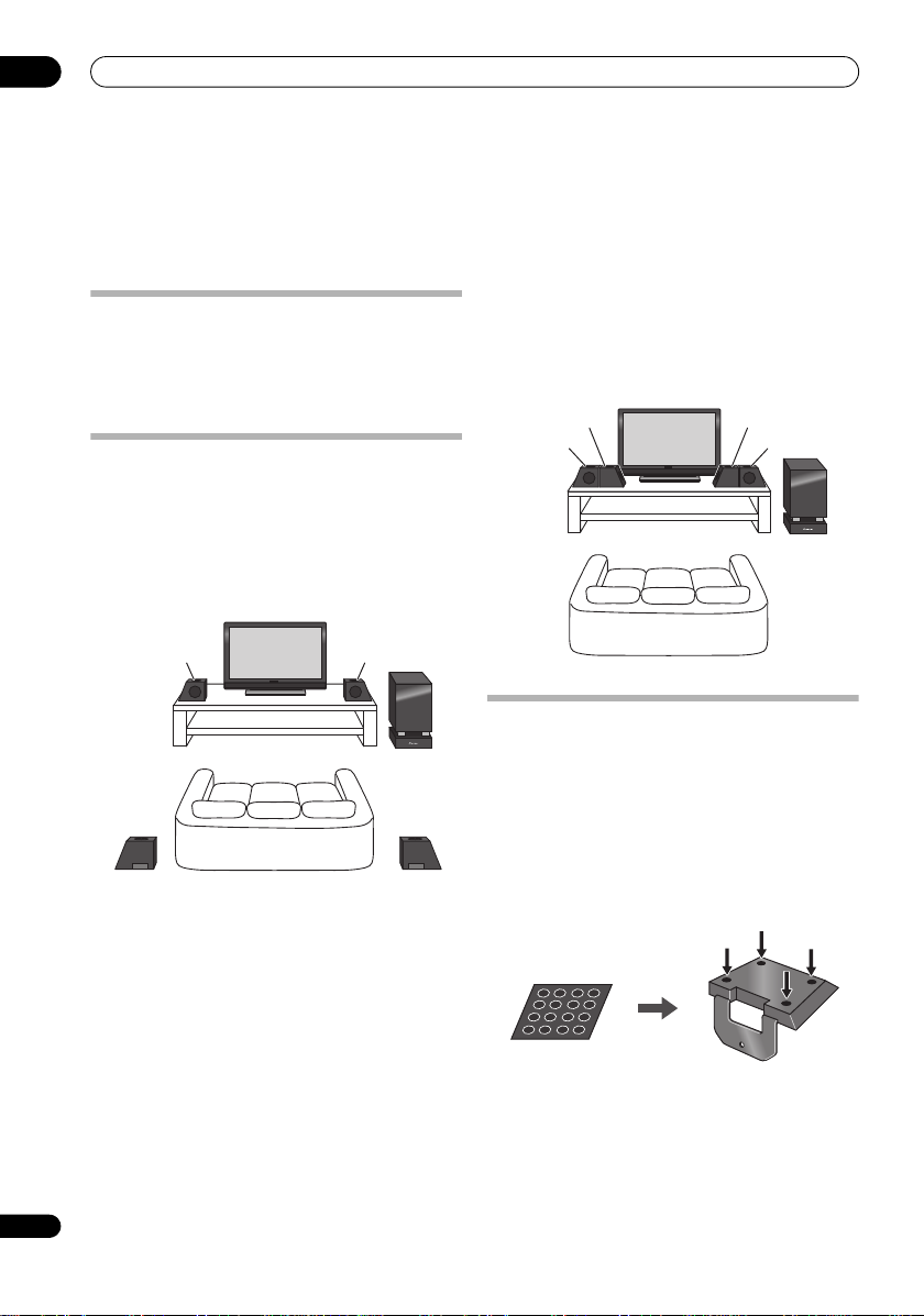
Home theater sound setup
Depending on the size and characteristics of your room,
you can place your speakers in one of two ways using this
system.
Standard surround setup
This is a standard multichannel surround sound speaker
setup for optimal 5.1 channel home theater sound.
Front surround setup
This setup is ideal when rear surround speaker
placement isn’t possible or you want to avoid running
long speaker cables in your listening area. Use this setup
together with the Front Stage Surround Advance modes
in page 33.
6
En
Preparing the speakers
This unit comes with speaker bases that can be used to
adjust the speakers to the design of the room in which
they are placed.
Using the supplied speaker bases
1 Attach the non-skid pads to the speaker bases, as
shown below.
Use the adhesive side of the pads to attach them to the
base of each speaker base.
Page 7

Speaker Setup Guide
Speaker
Screw
Speaker base
2 Attach the speaker bases.
Place the speaker atop a supplied speaker base, and fix
the base in place by using one of the supplied screws.
• The supplied speaker bases come in two different
shapes. You can determine the correct base for a
speaker by checking if the screw’s location lines up
correctly when the speaker is placed atop the base.
(There are specific bases for the front/center (L) and
surround speaker (R), and for the front/center (R) and
surround speaker (L), with two of each type included.)
When not using the supplied speaker bases
• Attach the non-skid pads to the base of each of
the front/center and surround speakers (as shown).
Use the adhesive side of the pads to attach them to the
base of each speaker.
Non-skid pads x 16
Front/center and surround speakers
01
Connect the speaker system
Refer to Connecting up to connect the speakers properly.
After connecting everything, place the speakers as
shown in the diagram above for optimal surround sound.
After placing the speakers, run the Auto MCACC setup
(page 27) to complete your surround sound setup.
Additional notes on speaker placement
• Install the main front left and right speakers at an
equal distance from the TV.
• When using the Standard surround setup, install the
surround speakers slightly above ear level for
optimum effect.
• When using the Front surround setup, separate the
left and right speakers by about 1.5 m for optimum
effect.
Precautions:
• Do not place the speaker on an unstable surface, as
doing so may cause the speaker to fall and cause
damage or bodily injury.
• All speakers supplied with this system are
magnetically shielded. However, depending on the
installation location, colour distortion may occur if a
speaker is installed extremely close to the screen of a
television set. If this happens, turn the power switch
of the television set OFF, and turn it ON after 15 min
to 30 min. If the problem persists, place the speaker
system away from the television set.
• For safety, make sure that there is no exposed bare
speaker wire outside of the speaker terminals.
• Do not connect the supplied speakers with any other
amplifier. This may result in malfunction or fire.
• Do not connect any speakers other than those
supplied to this system.
• The speaker system grill cannot be removed. Do not
try to forcibly remove it since doing so may damage
the grille.
• When cleaning the cabinet, use the provided
cleaning cloth.
Do not allow alcohol, thinner, benzene, or
insecticides to come into contact with the surface,
since finish discoloration may occur.
Also, when using chemically impregnated cleaning
cloths, follow their precautions carefully.
7
En
Page 8
02
FRONT
R
R
L
RLLRL
AM LOOP
FM
UNBAL 75 Ω
FRONTCENTER SURROUND SUBWOOFER
OPTICAL
IN 1
IN 2
OUT1OUT
2
HDMI
OUT IN 3
SYSTEM
IN 2 IN 1
AC IN
SPEAKERS (8 Ω
)
ANALOG
AUDIO IN
ANTENNA
DIGITAL
CONTROL
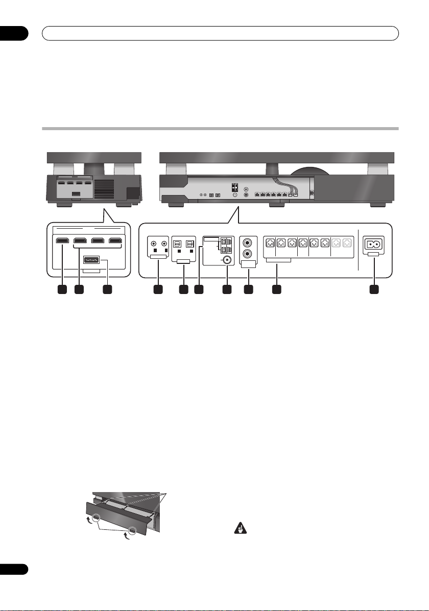
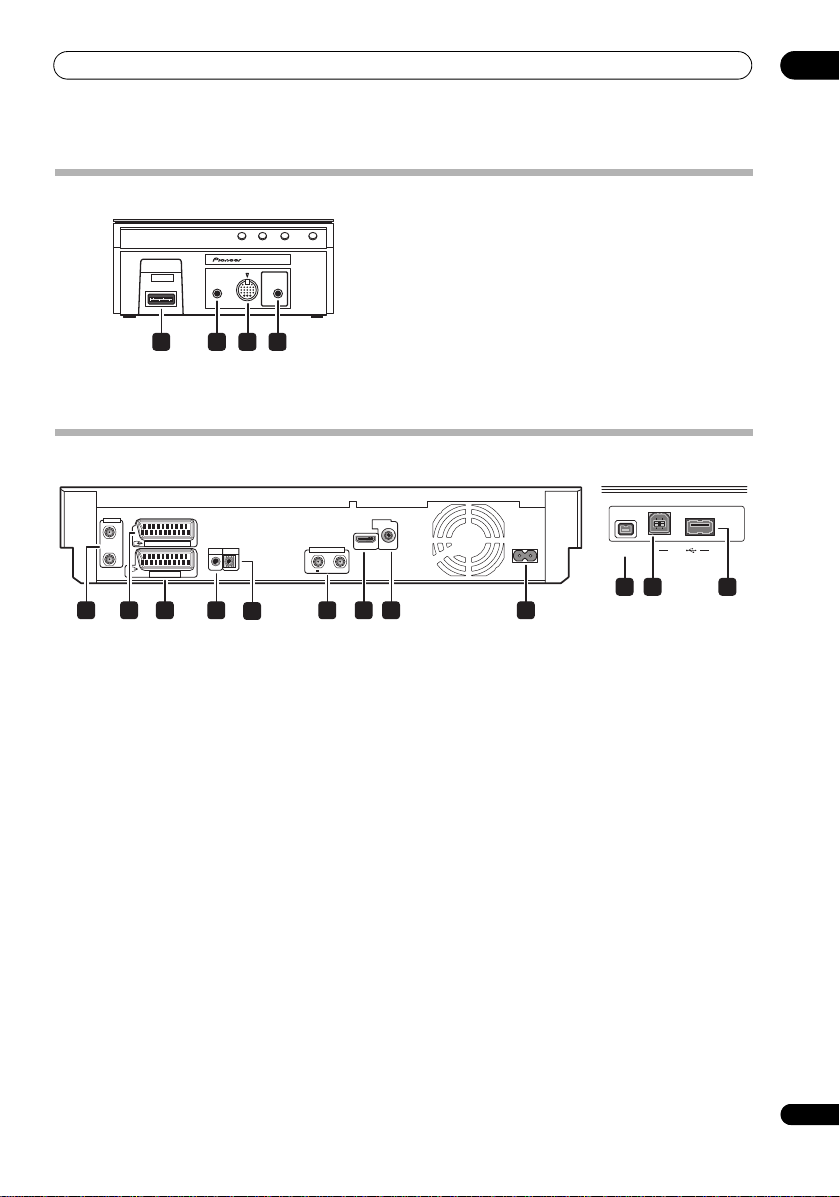
Rear panel Side panel
1 4 5 8 9
10
7632
A
B
Connecting up
Chapter 2
Connecting up
Receiver subwoofer
HDMI
OUT IN 3
IN 2 IN 1
SYSTEM
Rear panel
1 HDMI OUT connector
Connect to a television that has an HDMI terminal.
2 HDMI IN connectors (x3)
Use high-quality audio/video connection with compatible
HDMI devices. Connect the included HDD/DVD recorder
to HDMI IN 1.
To select this input, choose HDMI 1 to HDMI 3.
3 SYSTEM connector
Connect to the display unit.
Side panel
• There is a cover over the connectors on the side
panel.
A. When making connections, lift the two hooks and
remove the cover.
B. Once connections are finished, line up the three
positions and place the cover back in its original
position.
8
En
4 CONTROL OUT jacks (x2)
Connect the supplied HDD/DVD recorder to the
OUT 1
jack with the supplied control cable. You can
connect another component to the other Control Out jack.
5 DIGITAL OPTICAL IN jacks (x2)
To listen to optical digital audio, change the input to
Digital 1 or Digital 2.
When the digital output jacks of your TV are connected to
these jacks, set ‘TV Input’ (see page 40).
6 AM LOOP antenna terminal
7 FM antenna socket
8 ANALOG AUDIO IN jacks
Handle sound from an external component by using
stereo audio code. To listen to analog audio, change the
input to Analog.
When the analog output jacks of your TV are connected
to these jacks, set ‘TV Input’ (see page 40).
9 SPEAKERS terminals
Match the colours of the speaker cords to their respective
connectors.
10 AC IN – Power inlet
Important
• You must connect the supplied HDD/DVD recorder
with a control cable. If not, the HDD/DVD recorder
may not operate properly.
CONTROL
Page 9
Connecting up
USB
DV IN
4321 96 7 8
5
10 11 12
Rear panel
Front panel
Back of display unit
F.AUDIO
iPod
SYSTEM
1 2 3 4
1 SYSTEM connector
Connect to the receiver subwoofer.
HDD/DVD Recorder
DISPLAY UNIT
MCACC
SETUP MIC
02
2 F.AUDIO input
To listen to audio from an external component, connect
with a stereo mini-plug cable. Once connected, the input
automatically changes to Front Audio In.
3 iPod input terminal
Use to connect your Apple iPod as an audio source.
When you connect an iPod, the input automatically
changes to iPod.
4 MCACC SETUP MIC jack
Use to connect the supplied microphone for the Auto
MCACC setup (see page 27).
ANTENNA
IN
AV 2 (INPUT 1/DECODER)
OUT
AV 1 (RGB) – TV
CONTROL
G-LINK
IN
Rear panel
1 ANTENNA IN (RF IN)/OUT
Connect your TV antenna to the ANTENNA IN (RF IN)
jack. The signal is passed through to the ANTENNA OUT
jack for connection to your TV.
2 AV2(INPUT 1/DECODER) AV connector
Audio/video input/output SCART-type AV connector for
connecting to a VCR, or other equipment with a SCART
connector. The input accepts video, S-Video and RGB.
See AV2/L1 In on page 155 for how to set this up.
3 AV1(RGB)-TV AV connector
Audio/video output SCART-type AV connector for
connecting to a TV or other equipment with a SCART
connector. The video output is switchable between video,
S-Video and RGB. See AV1 Out on page 154 for how to set
this up.
4G-LINK™
Use to connect the supplied G-LINK™ cable to enable
GUIDE Plus+
etc.
5 CONTROL IN
Connect to the CONTROL OUT 1 jack of the receiver
subwoofer.
®
to control an external satellite receiver,
ANTENNA(DIGITAL)
OUT
5 V
DIGITAL
AUDIO OUT
COAXIAL
HDMI OUT
IN
30 mA
AC IN
6 ANTENNA (DIGITAL) IN/OUT
Connect your DTV antenna to the ANTENNA (DIGITAL)
IN jack. The signal is passed through to the ANTENNA
(DIGITAL) OUT jack for connection to your TV.
7 HDMI OUT
Connect to the HDMI IN 1 jack of the receiver subwoofer.
8 DIGITAL AUDIO OUT (COAXIAL)
Coaxial digital audio jack for connecting to Dolby Digital/
DTS/MPEG decoder or other equipment with a digital
input.
9 AC IN – Power inlet
Front panel
On the front panel there is a flip-down cover that hides
more connections.
10 DV IN
A DV input i.LINK connector, suitable for connecting a
DV camcorder.
11 USB port (Type B)
USB port for connecting a PictBridge-compatible printer
or PC.
12 USB port (Type A)
USB port for connecting a digital camera, keyboard or
other USB device.
9
En
Page 10
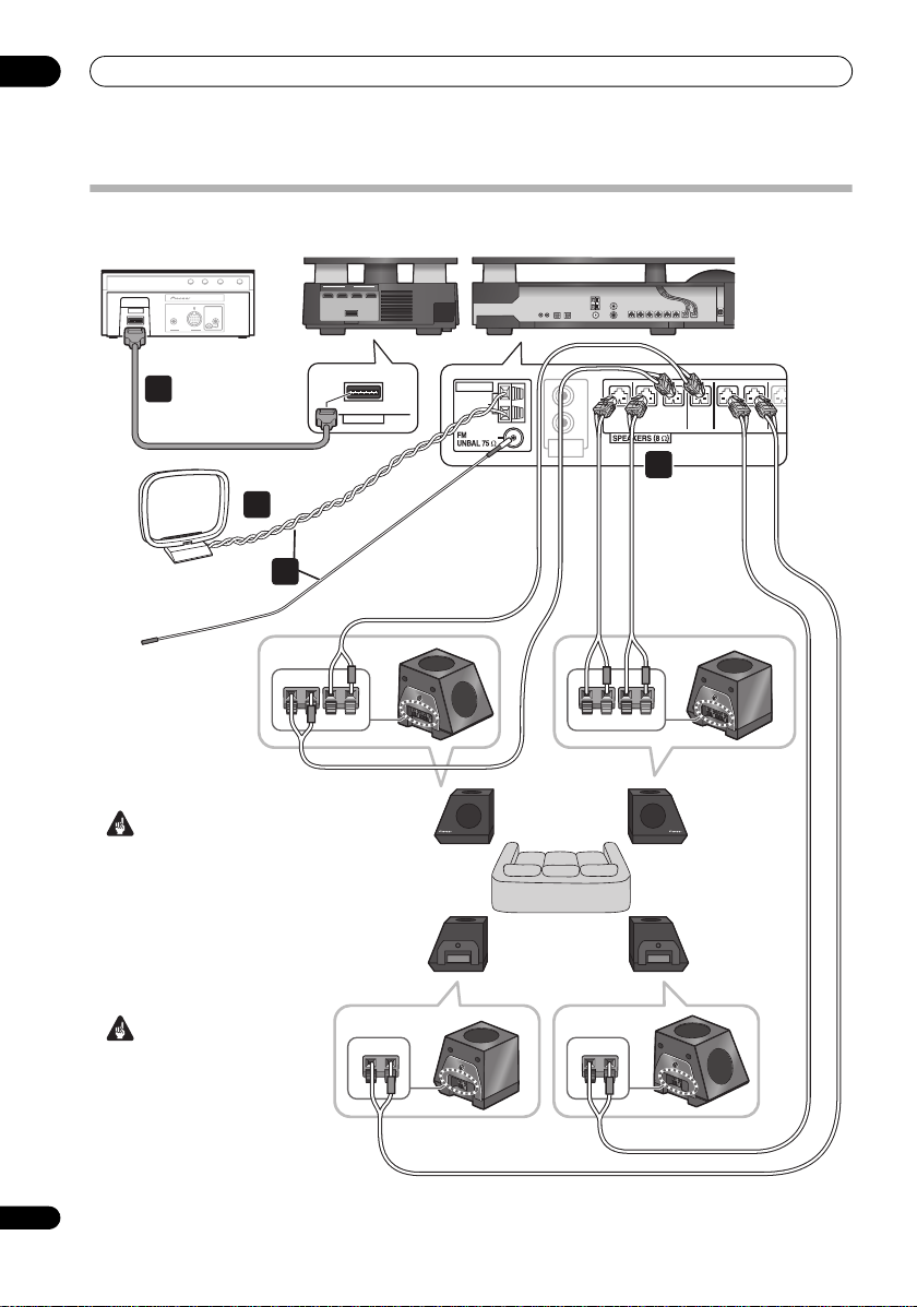
02
AM loop antenna
FM antenna
Rear panel
Display unit
Receiver subwoofer
Display cable
Front/center
speaker (R)
Front/center
speaker (L)
Surround
speaker (R)
Surround
speaker (L)
Side panel
2
F.AUDIO
DISPLAY UNIT
INPUT
iPod
MCACC
SETUP MIC
SYSTEM
1
FRONT
R
R
L
RLLRL
AM LOOP
FRONT
CENTER SURROUND SUB
ANALOG
AUDIO IN
ANTENNA
3
4
FRONT-L
CENTER-L
SURROUND-L
SURROUND-R
FRONT-R
CENTER-R
Listening positionListening position
Connecting up
Basic connections
OUT IN 3
HDMI
IN 2 IN 1
SYSTEM
Important
• When connecting this system
or changing connections, be
sure to switch power off and
disconnect the power cord from
the wall socket.
After completing all
connections, connect the
power cords to the wall socket.
SYSTEM
10
En
WARNING
• Pioneer bears no responsibility
for accidents resulting from
faulty assembly or installation,
insufficient mounting strength
of walls, mounting fixtures (or
other building fixtures), misuse
or natural disasters.
Page 11
Connecting up
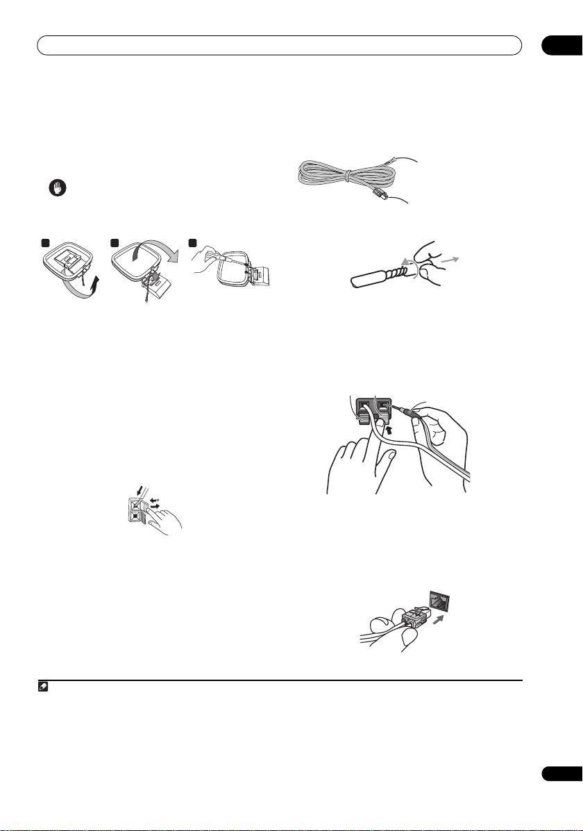
Note
a b c
1
2
3
Colour-coded wire
02
1 Connect the display unit to the receiver subwoofer.
Plug the display cable into the connector on the rear of
the display unit, then plug the other end of the display
cable into
SYSTEM
connector on the receiver subwoofer.
Caution
• Do not attempt to attach the display unit to the wall.
2 Assemble the AM loop antenna.
a. Bend the stand in the direction indicated by the
arrow.
b. Clip the loop onto the stand.
c. If you want to fix to a wall or other surface, perform
step b after first securing the stand with screws.
It is recommended that you determine the reception
strength before securing the stand with the screws.
3 Connect the AM and FM antennas
a. Connect one wire of the AM loop antenna to each AM
antenna terminal
2
.
1
.
For each terminal, press down on the tab to open;
insert the wire, then release to secure.
b. Push the FM antenna
3
plug onto the center pin of the
FM antenna socket.
4 Connect each speaker.
• Each speaker cable has a colour-coded connector at
one end and two wires at the other end.
Colour-coded wire
(Connect to speaker)
Colour-coded connector
(Connect to receiver subwoofer)
• Twist and pull off the protective shields on each wire.
• Connect the wires to the speaker. E ach speaker in the
illustration can be identified by means of the colourcoded indicator provided on the rear-surface model
label. Match the colour-coded wire with the colour
indicator on the model label, then insert the colourcoded wire into the red (+) side and the other wire
into the black (–) side.
Black (–) Red (+)
• Connect the other end to the colour-coded speaker
terminals on the side of the receiver subwoofer. Make
sure to insert completely.
Be careful when inserting the speaker plug, as it
must be inserted in the proper direction when being
plugged into one of the terminals. Please make sure
to connect correctly.
1 • Keep antenna cables away from other cables, the display unit, receiver subwoofer and HDD/DVD recorder.
• If reception with the supplied antenna is poor, see Improving poor FM reception and Improving poor AM sound on page 35 or Connecting
external antennas on page 42.
• Do not attach any antenna other than the provided loop antenna, or an external antenna as described on page 42.
2 • Don’t let it come into contact with metal objects and avoid placing near computers, television sets or other electrical appliances.
• If radio reception is poor, you may be able improve it by re-inserting each antenna wire into the opposite terminal.
• For best reception, do not untwist the AM loop antenna wires or wrap them around the loop antenna.
3 To ensure optimum reception, make sure the FM antenna is fully extended and not coiled or hanging at the rear of the unit.
11
En
Page 12
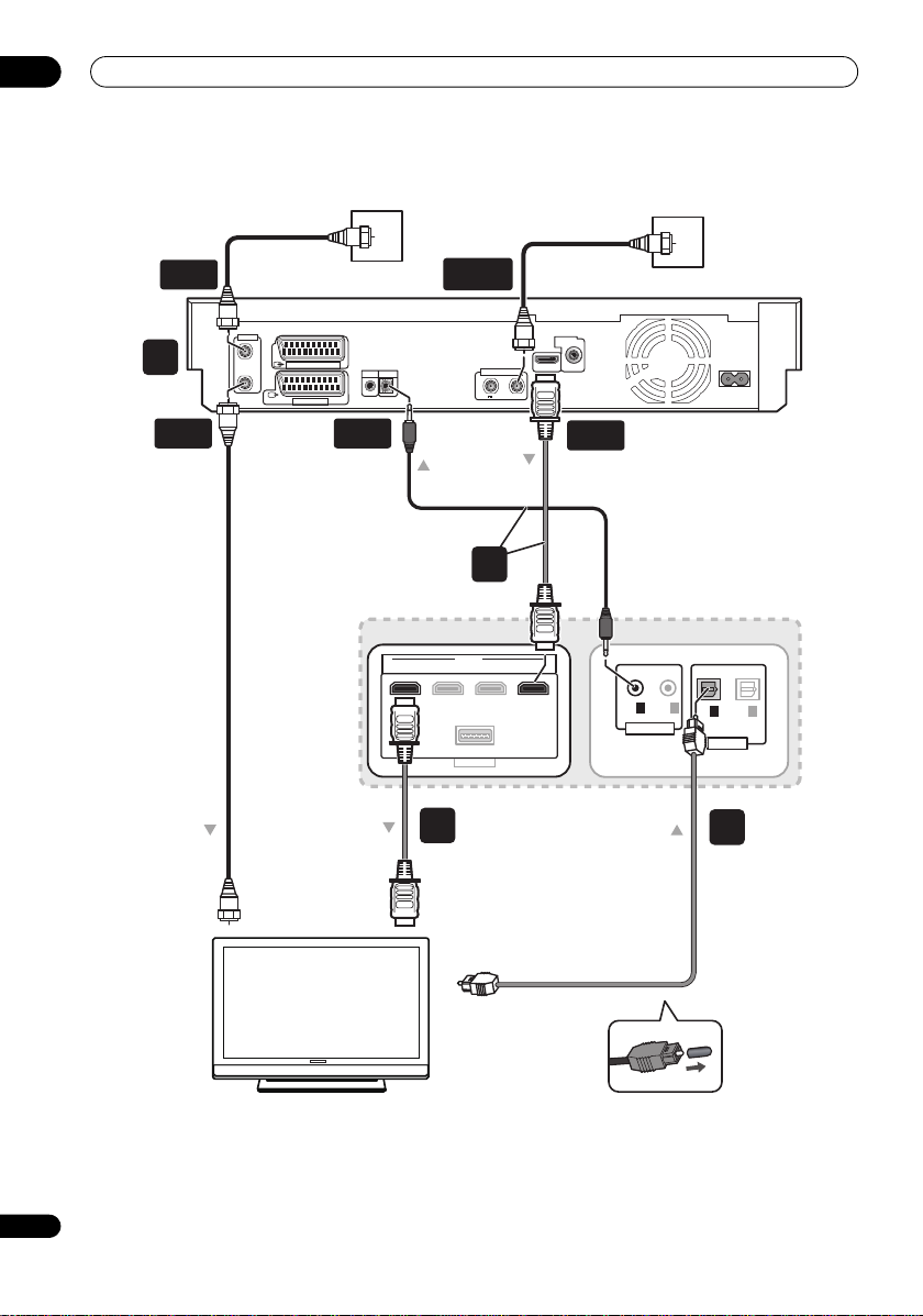
02
HDMI
OUT IN 3
SYSTEM
IN 2 IN 1
OPTICAL
IN 1
IN 2
OUT1OUT
2
DIGITAL
CONTROL
TV
7
6
8
5
Antenna wall outlet or
indoor antenna
Antenna wall outlet
From digital audio
output (optical)
RF antenna cable
RF antenna cable
RF antenna cable
To Antenna in
To HDMI input
ANTENNA
OUT
CONTROL
IN
HDMI
OUT
ANTENNA
IN
ANTENNA
(DIGITAL) IN
Receiver subwoofer
Rear panel
Side panel
HDD/DVD Recorder
Connecting up
ANTENNA
IN
OUT
AV 2 (INPUT 1/DECODER)
AV 1 (RGB) – TV
G-LINK
CONTROL
IN
ANTENNA(DIGITAL)
OUT
5 V
DIGITAL
AUDIO OUT
COAXIAL
HDMI OUT
IN
30 mA
AC IN
12
En
Page 13
Connecting up
Note
To AC outlet
To AC outlet
Receiver subwoofer
HDD/DVD recorder
02
Caution
• These speaker terminals carry HAZARDOUS LIVE
voltage. To prevent the risk of electric shock when
connecting or disconnecting the speaker cables,
disconnect the power cord before touching any
uninsulated parts.
• Do not connect any speakers other than those
supplied to this system.
• Do not connect the supplied speakers to any
amplifier other than the one supplied with this
system. Connection to any other amplifier may result
in malfunction or fire.
• After connecting the plugs, pull lightly on the cables
to make sure that the ends of the cables are securely
connected to the terminals. Poor connections can
create noise and interruptions in the sound.
• If the cables’ wires happen to be pushed out of the
terminals, allowing the wires to come into contact
with each other, it places an excessive additional load
on the amp. This may cause the amp to stop
functioning, and may even damage the amp.
5 Connect the HDD/DVD recorder to the receiver
subwoofer.
a. Plug the control cable into the CONTROL OUT 1 jack
on the side of the receiver subwoofer.
Plug the other end of the cable into the CONTROL IN
jack on the rear of the HDD/DVD recorder.
b. Plug the HDMI cable into the HDMI IN 1 jack on the
rear of the receiver subwoofer.
Plug the other end of the cable into the HDMI OUT
jack on the rear of the HDD/DVD recorder.
7 Connect an audio cable from your TV to the
receiver subwoofer.
• To listen to TV audio on this unit, connect the TV’s
audio output to DIGITAL OPTICAL IN 1 on the
receiver subwoofer.
To use the HDMI Control function when you are
connected to a supported Pioneer Flat Screen TV, you
must connect via HDMI.
• You must first set ‘TV Input’ to switch the audio from
a Flat Screen TV with the HDMI Control function or to
switch the input source of this unit to TV audio and
operate your TV with the supplied remote control. For
more information, see Operating Pioneer Flat Screen
TV and TVs on page 22 and Audio input settings from
TVs (TV Input) on page 40.
8 Connect a TV antenna.
• Connect the TV antenna from your TV to the
HDD/DVD recorder. See Connecting a TV antenna on
page 62 to connect the antenna.
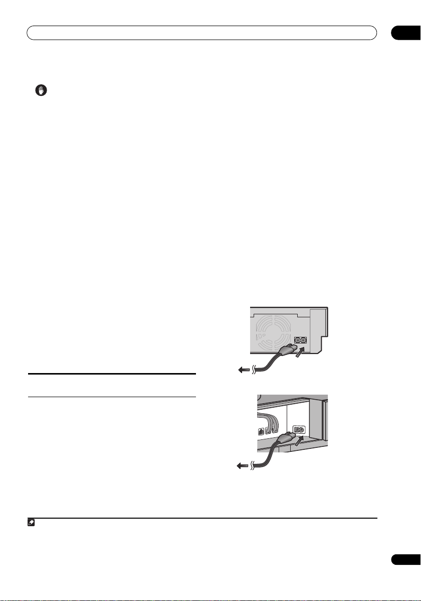
9 Connect the power cord.
1
• Connect each power cord to the AC inlet on the HDD/
DVD recorder and the receiver subwoofer. Connect
each power cord to a wall socket in the following
order: 1. HDD/DVD recorder 2. Receiver subwoofer 3.
TV.
AC IN
Note that unless the control cable is connected,
can’t use the remote control with the HDD/DVD recorder.
6 Connect the receiver subwoofer to your TV.
•Connect the HDMI OUT jack on receiver subwoofer
to an HDMI input on your TV.
• You can have audio from the receiver subwoofer, as
well as audio and video from the HDD/DVD recorder,
output to your TV by connecting with a single HDMI
cable.
1 • Do not use any power cord other than the one supplied with this system.
• Do not use the supplied power cord for any purpose other than connecting to this system.
• After connecting this unit to an AC outlet, a 15-second initialization process be gins. You cannot carry out any operations during initializatio n.
The HDMI indicator on the display unit blinks during initialization, and you can turn this unit on once it has stopped blinking.
you
• Run the cords that are connected to the side panel of
the receiver subwoofer over the back side of the unit,
and replace the cover on the side panel.
13
En
Page 14
03
Top buttons
1 2 3
4 75 6
Controls and displays
Chapter 3
Controls and displays
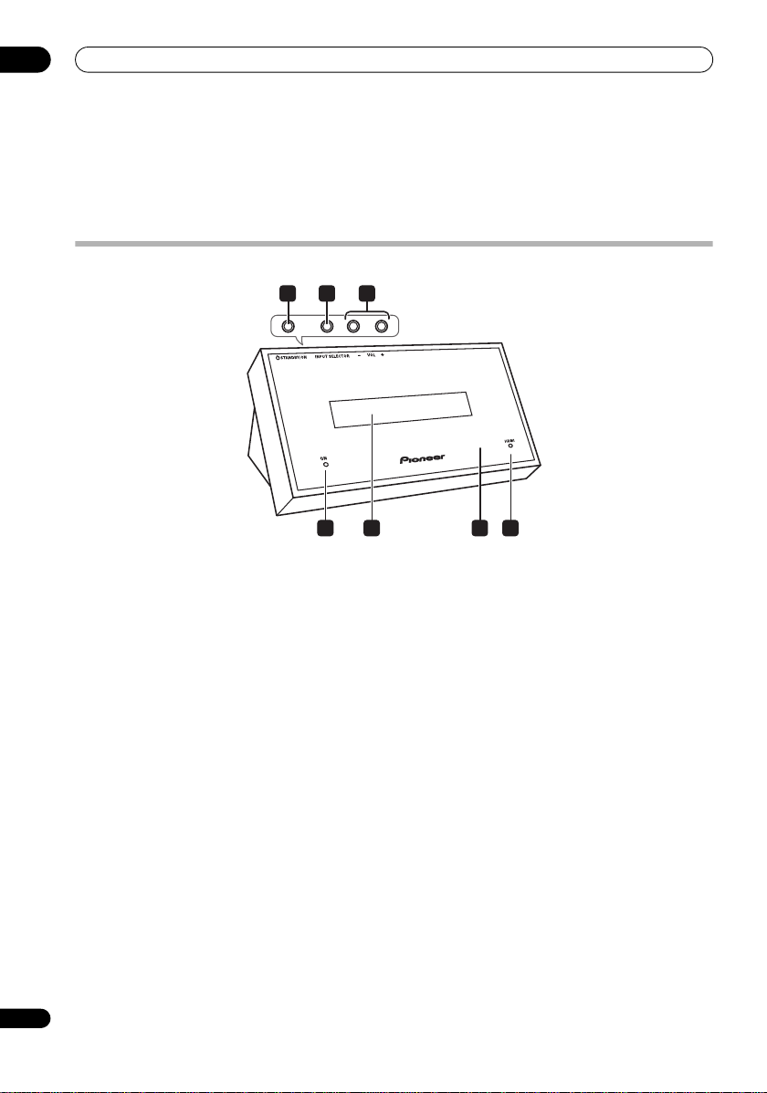
Display unit
1 STANDBY/ON
Press to switch the receiver subwoofer on/into standby.
2 INPUT SELECTOR (page 42)
Press repeatedly to select one of the external audio
inputs (HDMI 1 to HDMI 3, Digital 1, Digital 2, Analog,
iPod or Front Audio In).
3 VOL +/– buttons
Use to adjust the volume.
4 POWER ON indicator (Blue)
5 Front panel display
See below for details.
6 IR remote sensor (page 26)
7 HDMI indicator (Red)
Lights when this receiver subwoofer is connected to
HDMI (HDCP) compatible component.
Also lights during initialization, after you plug this unit
into an AC outlet.
14
En
Page 15
Controls and displays
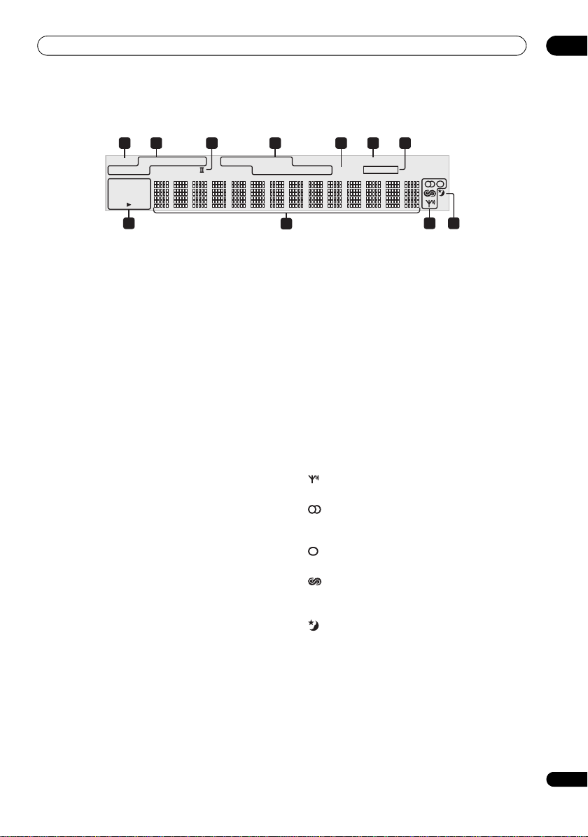
Display
21 4 65
DIRECT STEREO F.S.SURR.
ADV.SURR.
2
DTS 96/24
DSD PCM
DIGITAL
PRO LOGIC
2
8 10
1DIRECT
Lights when Direct Sound is selected (i.e. Effective
Sound is off) (page 31).
2 Listening mode indicators
STEREO
Lights when the Stereo mode is selected or when a
stereo source is being played back in the Auto
listening mode (page 33).
F.S.SURR.
Lights when one of the Front Stage Surround
Advance listening modes is selected (page 33).
ADV.SURR.
Lights when one of the Advanced Surround listening
modes is selected (page 32).
3 2 PRO LOGIC II
Lights during Dolby Pro Logic II decoding (page 32).
4 Sound processing indicators
Lights when any of the Loudness, Midni ght, Quiet or tone
controls feature is selected (page 34).
5S.RTRV
Lights when Sound Retriever is active (page 33).
6 HDMI THROUGH
Lights when HDMI Mode is set to Through Mode.
7 MCACC
Lights when MCACC Effect is switched on (page 34).
Blinks during Auto MCACC Setup (page 27).
3 7
LOUDNESS MIDNIGHT
QUIET TONE S.RTRV MCACC
DNR DIALOG
9
HDMI THROUGH
11
8 Digital format indicators
2 DIGITAL
Lights during playback of a Dolby Digital source
(page 31).
DTS
Lights during playback of a DTS source (page 31).
DTS 96/24
Lights during playback of a DTS 96/24 decoding
(page 31).
DSDPCM
Lights during DSD (Direct Stream Digital) to PCM
conversion with SACDs.
PCM
Lights during playback of PCM signals.
9 Character display
10 Tuner indicators
Lights when a broadcast is being received.
Lights when a stereo FM broadcast is being received
in auto stereo mode.
Lights when FM mono reception is selected.
Lights when in one of the RDS display or search
modes.
11
Lights when sleep timer is active (page 47).
03
15
En
Page 16
03
Controls and displays
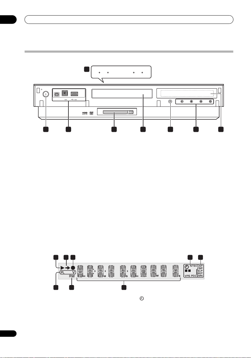
HDD/DVD Recorder
HDD DVD EPG
8
STANDBY/ON
DV IN
USB
1 2 3 4 65 7
• The image above represents when the front door is open.
1 STANDBY/ON
Press to switch the recorder on/into standby.
2 Front panel inputs
See Front panel on page 9 for more information on these.
3 COMMON INTERFACE slot
Slot for CA module and smart card used to decode
scrambled D.TV channels. See Common Interface on
page 17.
4 Disc tray
5 OPEN/CLOSE
Press to open/close the disc tray.
6 PLAY
Press to start or restart playback.
STOP
Press to stop playback.
HDMI
Top of the unit
OPEN/
CLOSE
STOP REC
STOP RECPLAY
REC
Press to start recording. Press repeatedly to set the
recording time in 30 minute blocks.
F STOP REC
Press to stop recording.
7 Front panel display
See below for details.
8 HDD indicator
Lights when the hard disk (HDD) is selected.
DVD indicator
Lights when the DVD drive is selected.
EPG indicator
Lights when the EPG data is downloading.
HDMI indicator
Lights when this recorder is connected to HDMI
(HDCP) compatible component.
Display
1
2 3 4 5
8 7 6
1
Lights during playback; blinks when playback is paused.
2
Lights when copying.
3
Lights during recording; blinks when recording is paused.
16
En
L
R
4 (page 98)
Lights when a timer recording has been set.
(Indicator blinks if the timer has been set to DVD but
there isn’t a recordable disc loaded, or the timer has
been set to HDD but the HDD is not recordable.)
Page 17

Controls and displays
NTSC
Lights when the video output signal format is NTSC.
(page 155)
Indicates which channels of a bilingual broadcast are
recorded.
VPS/PDC (page 98)
Lights when receiving a VPS/PDC broadcast during a
VPS/PDC-enabled timer recording.
5 Recording quality indicators (page 95)
XP
Lights when the recording mode is set to XP (high
quality).
SP
Lights when the recording mode is set to SP
(standard play).
LP/SLP
Lights when the recording mode is set to LP (long
play) or SLP (super-long play).
EP/SEP
Lights when the recording mode is set to EP
(extended play) or SEP (super-extended play).
MN
Lights when the recording mode is set to MN
(manual recording level) mode.
6 Character display
7R/RW
Lights when a recordable DVD-R or DVD-RW disc is
loaded.
8PL (page 118)
Lights when a VR mode disc is loaded and the
recorder is in Play List mode.
V
Lights when an unfinalized Video mode disc is loaded.
03
Common Interface
To receive scrambled D.TV channels you will need a CA
module and smart card provided by your service provider.
Different CA modules support different encryption
systems. This recorder is designed to work with modules
that support the DVB standard. Contact your service
provider to obtain the right kind of CA module.
Note that neither CA modules nor smart cards are
supplied or sold by Pioneer.
Inserting a CA module
The Common Interface card slot is located on the inside
of the cover of the recorder’s front panel.
1 Push down on the PUSH OPEN tab to access the
Common Interface.
2 Insert the CA module into the card slot as far as
it will go.
The Common Interface card slot accepts Type I and Type
II PC Cards (PCMCIA cards).
17
En
Page 18
03
ON
SYSTEM
INPUT
SELECT
OFF
HDMI 1 HDMI 2 HDMI 3
DVR BD DVD
INPUT
TV
FM / AM
TV
TOP MENU
DISC
NAVIGATOR
HOME
MENU
DISPLAY
LIGHT
TOOLS
MENU
PAGE
RETURN
VOL
SYSTEM
SYSTEM
CONTROL
MUTE
GUIDE
TV
VOL
INFO
SETUP
SYSTEM
SURR
GENRE
SLEEP
EXIT
MCACC SOUND
DIRECT
ADV.
SURR
TEST
TONE
SOUND
RTRV
LINE
F.S .
SURR
5
9
11
12
8
4
10
7
13
14
1
3
2
6
6
15
16 171918
20 21 22
23 24
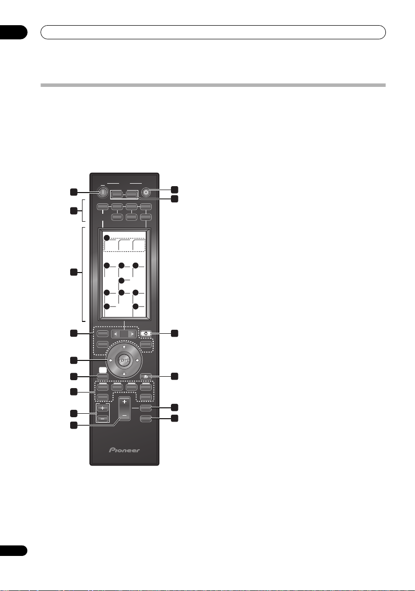
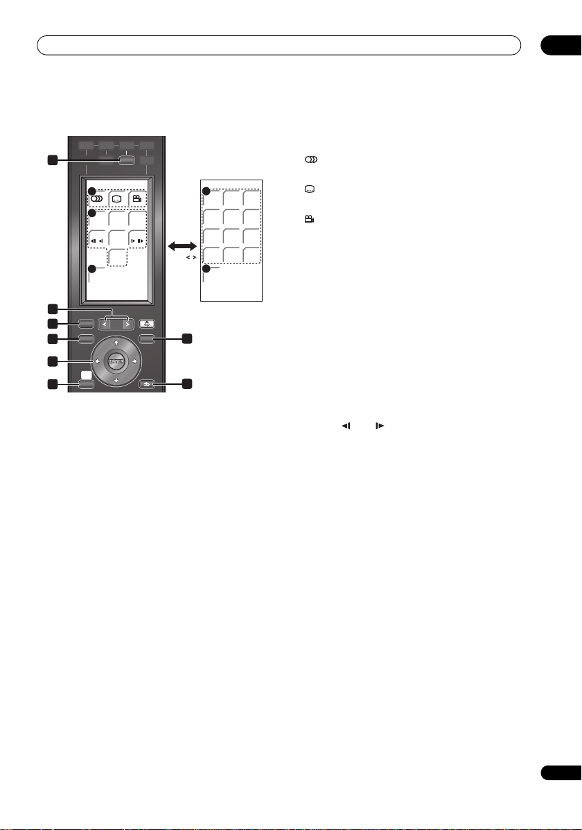
Remote control
Controls and displays
• For more information on using the remote control, see Operating the remote control on page 29.
Operating the receiver subwoofer
This section explains how to operate the remote control
for the receiver subwoofer. Note that th e controls change
when you have chosen the input function for separate
connected devices, such as an HDD/DVD recorder.
1 SYSTEM ON
Switches the receiver subwoofer and HDD/DVD recorder
to On.
18
En
2 SYSTEM OFF
Switches the receiver subwoofer and HDD/DVD recorder
to Off (Standby).
3TV INPUT
Select an input source of the TV.
TV
Switches the TV to On/Standby.
4 INPUT SELECT buttons
Change the input for the receiver subwoofer. You will also
need to press one of these buttons when operating
another connected component via this remote control.
DVR (HDMI 1)
Switches the input to the included HDD/DVD
recorder (
DVR) connected to HDMI 1.
The remote control switches to the HDD/DVD
recorder operating mode.
BD (HDMI 2)
Switches the input to the Blu-ray disc player (
BD)
connected to HDMI 2 (when a separately sold
Pioneer Blu-ray disc player is connected).
The remote control switches to the Blu-ray disc player
operating mode.
The Blu-ray disc player’s power can be switched
between on and standby using the button below.
DVD (HDMI 3)
Switches the input to the DVD player (
to
HDMI 3 (when a separately sold Pioneer DVD
DVD
) connected
player is connected).
The remote control switches to the DVD player
operating mode.
The DVD player’s power can be switched between on
and standby using the button below.
TV
Switches to the input selected at TV Input setup
(page 40).
FM/AM
Switches between FM and AM bands (page 35).
5 LCD touch screen
Displays the buttons used to control external components
such as a receiver subwoofer (
recorder (
HDD/DVR
player (
BD
) and DVD player (
SYSTEM
), Flat Screen TV (
DVD
). The current operating
), HDD/DVD
PDP
), Blu-ray disc
mode is displayed at the top of the remote control’s
screen.
Although the LCD touch screen disappears if you do not
perform any operations for a while, it appears when the
screen is touched or a button on the remote control is
pressed.
Page 19
Controls and displays
3
1
2
4
03
6 Other component button
Use to operate the HDD/DVD recorder or other
connected component.
7 LIGHT
The LCD touch screen’s illumination turns on and off
each time the button is pressed.
The illumination automatically turns off after 30 seconds.
When turned off by pressing the button, the display turns
off one minute later.
8 /// (cursor buttons) and ENTER
Use to control receiver functions.
9 SETUP
Use to access the menu system for surround sound
setup, tuner settings and so on (page 35, 37, 44, 47).
10 RETURN
Use to cancel settings.
11 TV VOL +/–
Use to adjust the volume of the TV.
12 SYSTEM VOL +/–
Use to adjust the volume of the receiver subwoofer.
13 MUTE
Mutes the sound or restores the sound if it has been
muted (adjusting the volume also restores the sound).
14 SYSTEM CONTROL
Use to switch to the receiver subwoofer operating mode
(SYSTEM) when this unit is in the other operating modes.
Press again to return to the previous operating mode.
LCD touch screen
15 SURR
Use to select a Surround mode (page 31).
ADV.SURR
Use to change the audio setting to Pioneer’s original
Advanced Surround mode (page 32).
F.S.SURR
Use to select a Front Stage Surround Advance mode
(page 33).
16 GENRE
Use to listen to audio in Genre Sync mode (page 33).
(This button is displayed only when the SYSTEM screen
is shown during HDD/DVD recorder operation.)
17 SOUND RTRV
Press to restore CD quality sound to compressed audio
sources (page 33).
18 DIRECT
Use to switch on/off the Effective Sound mode (page 31).
19 LINE
Press repeatedly to select one of the receiver subwoofe r’s
audio inputs (Digital 1, Digital 2, Analog, iPod or Front
Audio In) (page 42).
20 MCACC
Starts the Auto MCACC setup (page 27).
21 TEST TONE
Use to output the test tone (for speaker setup) (page 39).
22 SOUND
Press to access the sound menu, from which you can
adjust bass and treble, etc.
23 SLEEP
Press to set the sleep timer (page 47).
24 EXIT
Cancel settings and exit the SYSTEM screen.
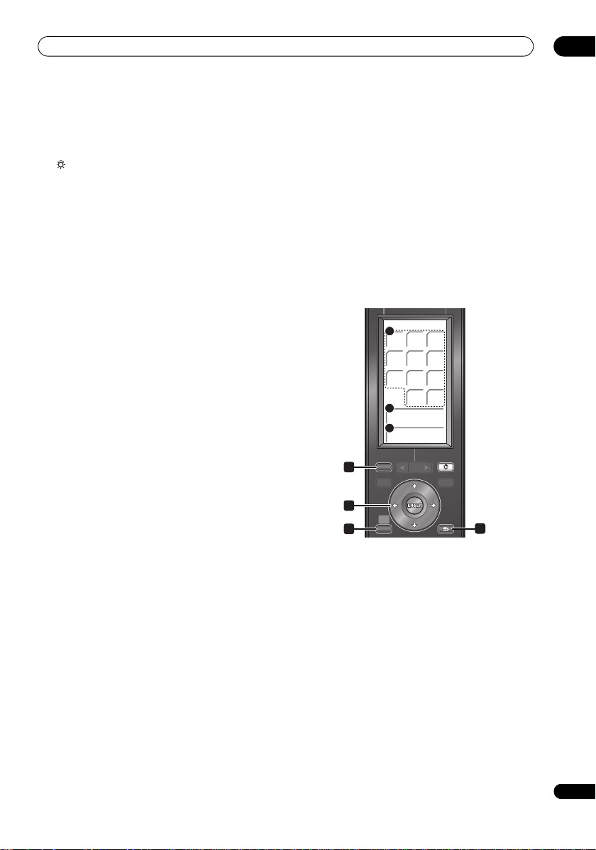
Operating the built-in FM/AM tuner
FM/AM
5
123
456
7809
CLEAR
6
TUNE
-
+
ST
-
+
LIGHT
PAGE
TOOLS
MENU
RETURN
DISPLAY
TOP MENU
DISC
NAVIGATOR
SETUP
HOME
MENU
7
1 DISPLAY
Use to display RDS information (page 36).
2 /// (cursor buttons) and ENTER
Use to control FM/AM tuner functions.
3SETUP
Use to access the menu system or tuner
settings.
4RETURN
Use to cancel settings.
LCD touch screen
5 Number buttons
Use to directly choose a preset radio station.
CLEAR
Press to clear an entry and start again.
6TUNE +/–
Use to find radio frequencies.
7ST +/–
Use to select a station preset.
19
En
Page 20

03
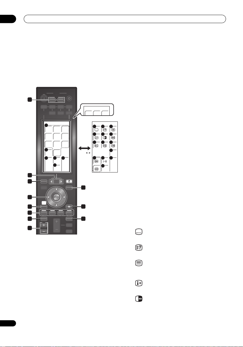
Controls and displays
Operating the supplied HDD/DVD Recorder
HDD/DVR 1/3
11 12 13
HDD/
DVD
14
15
CM
BACKCMSKIP
16
REC
18 19 20
HELP
1
DISPLAY
2
TOP MENU
3
DISC
NAVIGATOR
5
HOME
MENU
SETUP
6
8
GUIDE INFO
9
1 PAGE </>
Switch between pages on the LCD touch screen when
multiple pages are present.
2DISPLAY (page 112)
Displays/changes the on-screen information displays.
3 TOP MENU (page 104) / DISC NAVIGATOR
(page 106, 118)
Press to display the top menu if a DVD-Video or finalized
DVD-R/-RW (Video) disc is loaded, or the Disc Navigator
screen.
4 MENU (page 104)
Press to display the disc menu if a DVD-Video, finalized
DVD-R/-RW (Video mode) or finalized DVD+R/+RW disc
is loaded.
When in the GUIDE Plus+
®
system, use to jump directly
to the Menu bar.
5 /// (cursor buttons) and ENTER
Use to navigate all on-screen displays. Press ENTER to
select the currently highlighted option.
While watching D.TV press ENTER to display the Channel
List screen.
6HOME MENU
Press to display the Home Menu, from which you can
navigate many functions of the system.
7 RETURN
Press to go back one level in the on-screen menu or
display.
Also press to exit the MHEG application.
20
En
JUKE
BOX
STOP
REC
TIMER
REC
PAGE
SYSTEM
P.L I V E
TV
PA GE / PA GE /
17
REC
MODE
TIMER
ON/OFF
LIGHT
TOOLS
MENU
RETURN
4
7
10
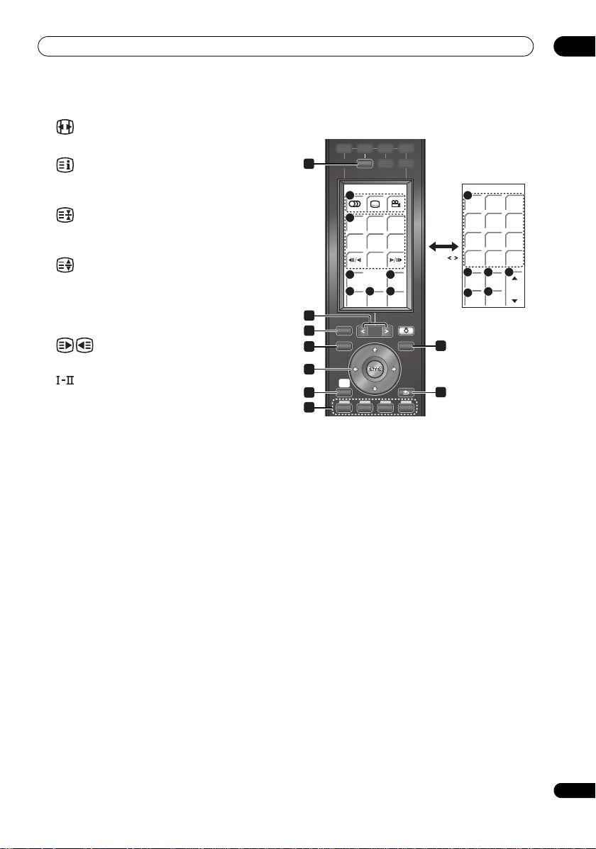
HDD/DVR 2/3
21 27
123
HDD/DVR 3/3
456
7809
22
A.TV/
CLEAR
D.TV
23 24
26
INPUT
+
CH
-
TV/
DVD
18 25
HELP TEXT
8 GUIDE Plus+
28
O.T.
COPY
®
Action buttons
Use when an EPG screen is displayed or when tuned to a
data channel of a digital broadcast. The function of each
button will be described on-screen, and changes
depending on the screen being displayed.
9 GUIDE
Press to display the EPG screen; press again to exit.
10 INFO
While watching D.TV, press to display information
banner.
LCD touch screen
11 HDD/DVD
Press to select the hard disk (HDD) or DVD for recording
and playback.
12 JUKEBOX (page 134)
Press to display the Jukebox screen of the HDD/DVD
recorder, from where you can copy music to the HDD for
playback.
13 P.LIVE TV (page 96)
Press to start recording the current TV channel, but with
playback paused, effectively pausing the broadcast.
14 Playback controls (page 103)
Press to start playback.
Press to stop playback.
Page 21

Controls and displays
03
Press to pause playback or recording.
,
Press to skip to the previous or next title/chapter/
track; or to display the previous or next menu page.
When GUIDE Plus+
previous/next page.
/ , / (page 108, 109)
Press to start reverse or forward scanning. Press
again to change the speed.
While paused, press and hold to start slow-motion
playback. Press repeatedly to change the playback
speed.
While paused, press to advance a single frame in
either direction.
When GUIDE Plus+
previous/next day.
15 CM BACK (commercial back)
Press repeatedly to skip progressively backward
through the video playing.
CM SKIP (commercial skip)
Press repeatedly to skip progressively forward
through the video playing.
16 Recording controls (page 95)
REC
Press to start recording. Press repeatedly to set the
recording time in blocks of 30 mins.
When the red action button is visible in a GUIDE
®
Plus+
screen, use for One-Button-Record.
STOP REC
Press to stop recording.
17 REC MODE (page 95)
Press repeatedly to change the recording mode (picture
quality).
18 HELP
Press for help on how to use the current GUI screen.
19 TIMER REC (page 75, 98)
Press to set a timer recording.
20 TIMER ON/OFF
This button cannot be used for the supplied HDD/DVD
recorder.
21 Number buttons
Use the number buttons for track/chapter/title
selection; channel selection, and so on.
CLEAR
Press to clear an entry and start again.
®
is displayed, use to display the
®
is displayed, use to display the
22 A.TV/D.TV
Press to switch between analog TV antenna input and
digital TV antenna input. The A.TV and D.TV indicators
on the front panel show which is selected.
23 TV/DVD
Press to switch between ‘TV mode’, in which you get the
picture and sound from the TV’s tuner, and ‘DVD mode’,
in which you get picture and sound from the system’s
tuner (or an external input).
24 INPUT (page 100)
Press to change the HDD/DVD recorder input to use for
recording.
25 TEXT
Press to display Teletext information (in European
countries except the UK) or to start the MHEG application
display (UK only) if available during digital broadcasts.
26 CH +/– (page 93)
Press to change the channel of the built-in TV tuner.
27 (AUDIO) (page 94, 111)
Press to change the audio language or channel.
(When the recorder is stopped, press to change the
tuner audio.)
(SUBTITLE) (page 111)
Press to display/change the subtitles included in
multilingual DVD-Video discs.
While watching D.TV, press to change the D.TV
subtitles.
(ANGLE) (page 112)
Press to switch camera angles on discs with multiangle scenes.
28 O.T. COPY (page 127)
Press to start One Touch Copy of the currently playing
title to DVD or the HDD.
21
En
Page 22
03
ON
SYSTEM
INPUT
SELECT
OFF
HDMI 1 HDMI 2 HDMI 3
DVR BD DVD
INPUT
TV
FM / AM
TV
TOP MENU
DISC
NAVIGATOR
HOME
MENU
DISPLAY
LIGHT
TOOLS
MENU
PAGE
RETURN
VOL
SYSTEM
SYSTEM
MUTE
GUIDE
TV
VOL
INFO
SETUP
PDP 1/2
MUTE
INPUT
123
456
7809
TV/
DTV
P
-
+
TV VOL
-
+
12
13
14 151617
6
9
3
5
7
10
4
1
PDP 2/2
EXIT
MUTE
TV VOL
-
+
2
8
11
18 19 20
21 22 23
24 25 26
28 291617
27
PA GE /
TV 1/2
123
Erscheint bei anderer
Einstellung als PioneerFlachbildfernseher.
Controls and displays
22
En
Operating Pioneer Flat Screen TV and TVs
First, refer to Setting up the remote to control your TV on
page 47 for information about setting up your TV’s
presets. Note that certain buttons may not work with
some TVs.
TELETEXT-related buttons can only be used with Pioneer
Flat Screen TVs.
1TV INPUT
Select an input source of the TV.
TV
Switches the TV to On/Standby.
2 PAGE </>
Switch between pages on the LCD touch screen when
multiple pages are present.
3DISPLAY
Displays the channel information.
4 TOOLS
Displays the TOOLS Menu.
5 /// (cursor buttons) and ENTER
Selects a desired item on the setting screen. Press
ENTER to executes a command.
6HOME MENU
Displays the HOME MENU screen.
7 RETURN
Restores the previous menu screen.
8 Colour (RED/GREEN/YELLOW/BLUE) buttons
Controls a BD player for HDMI Control functions only.
9 GUIDE
Displays the Electronic Program Guide in DTV/SAT
(Satellite) input mode.
10 INFO
Displays the channel information.
11 TV VOL +/–
Use to adjust the volume of the TV.
LCD touch screen
12 Number buttons
TV/External input mode: Selects a channel.
Teletext mode: Selects a page.
13 TV/DTV (For Pioneer Flat Screen TV only)
Switches the mode among TV and DTV.
14 P +/–
TV/External input mode: Selects a channel.
15 INPUT
Selects an input source of the Flat Screen TV.
16 MUTE
Mutes the sound.
17 TV VOL +/–
Sets the volume.
The following only apply to Pioneer Flat Screen TVs:
18
Jumps to Teletext subtitle page.
19
Displays hidden characters.
20
Selects the Teletext mode (all TV image, all TEXT image,
TV/TEXT image).
21
Displays the channel information.
22
TV/External input mode: Freezes a frame from a moving
image.
Press again to cancel the function.
Page 23
Controls and displays
BD 2/2
ENTER
CLEAR
123
456
7809
PLAY
MODE
FL
DIMMER
RESO-
LUTION
VIDEO
ADJ
VIDEO
SEL
17
18 19
20
22
21
PA GE /
7
3
4
6
8
5
9
2
1
03
23
Selects the screen size.
24
Displays an Index page for the CEEFAX/FLOF format.
Displays a TOP Over View page for the TOP format.
25
Teletext mode: Stops updating Teletext pages. Press
again to release the hold mode.
26
Teletext mode: Switches Teletext images. (full/upper half/
lower half)
27 EXIT
Press to exit the channel information.
28
Teletext mode: Selects a page.
29
Sets the sound multiplex mode.
Operating a Pioneer Blu-ray Disc player
HDMI 1 HDMI 2 HDMI 3
DVR BD DVD TV
INPUT
SELECT
10
11
12
HMG
14 15 16
2nd
AUDIO
DISPLAY
TOP MENU
DISC
NAVIGATOR
HOME
MENU
SETUP
1 (BD)
Switches the power for a Blu-ray disc player to
On/Standby.
2PAGE </>
Switch between pages on the LCD touch screen when
multiple pages are present.
3 DISPLAY
Press to display information.
4TOP MENU
Press to display the top menu of a BD-ROM or DVD-Video
disc.
5 TOOLS
Press to display/hide the TOOLS menu.
6 /// (cursor buttons) and ENTER
Use to navigate on-screen displays and menus.
Press ENTER to select an option or execute a command.
7HOME MENU
Press to display/hide the Home Menu.
8RETURN
Press to return to a previous screen.
9 Colour (RED/GREEN/YELLOW/BLUE) buttons
Use to navigate BD-ROM menus.
BD 1/2
2nd
VIDEO
PAGE
13
MENU
OPEN/
CLOSE
FM / AM
LIGHT
TOOLS
MENU
RETURN
23
En
Page 24

03
Controls and displays
LCD touch screen
10 (AUDIO)
Press to select the audio channel or language.
(SUBTITLE)
Press to select a subtitle display.
(ANGLE)
Press to change the camera angle during BD-ROM or
DVD-Video movie multi-angle scene playback.
11 Playback controls
Press to start or resume playback.
Press to stop playback (you can resume playback by
pressing ).
Press to pause playback; press again to restart.
,
Press to jump to the start of the previous/next
chapter/track.
,
Press to start reverse/forward scanning.
/ , /
Use for slow motion and step frame.
12 HMG
Press to display/hide the Home Media Gallery screen.
13 MENU
Press to display the BD-ROM or DVD-Video menus.
14 2nd AUDIO
When playing a BD-ROM on which secondary audio is
recorded, press to switch to the secondary audio.
15 2nd VIDEO
When playing a BD-ROM on which secondary video
(Picture-in-Picture) is recorded, press to switch to the
secondary video.
16 OPEN/CLOSE
Press to open and close the disc tray.
17 Number buttons
Use these to select and play the title/chapter/track
you want to watch or listen to and to select items
from menus.
ENTER
Press to execute the selected item or enter a setting
that has been changed, etc.
CLEAR
Press to clear the numeric number, etc.
18 PLAY MODE
Press to display/hide the Play Mode screen.
19 VIDEO ADJ
Press to display/hide the Video Adjust menu.
20 FL DIMMER
Press to switch the brightness of the player’s front panel
display. The FL OFF indicator lights when Off is selected.
21 VIDEO SEL
Press to switch the player’s terminal from which the
video signals are output. Use to switch between digital
output (HDMI output) and analog output (Component
Video output, S-Video output or Video output) (the
signals are only output from the selected video
output terminal).
22 RESOLUTION /
Use these to switch the output video resolution from the
player’s HDMI OUT or COMPONENT VIDEO output
terminals.
24
En
Page 25
Controls and displays
PA GE /
DVD 2/2
ENTER
CLEAR
123
456
7809
PLAY
MODE
12
13
8
5
7
3
4
6
2
1
Operating a Pioneer DVD player
HDMI 1 HDMI 2 HDMI 3
DVR BD DVD TV
INPUT
SELECT
9
10
11
ZOOM
DISPLAY
TOP MENU
DISC
NAVIGATOR
HOME
MENU
SETUP
1 (DVD)
Switches the power for a DVD player to On/Standby.
2 PAGE </>
Switch between pages on the LCD touch screen when
multiple pages are present.
3 DISPLAY
Press to display information.
4 TOP MENU
Press to display the top menu of a DVD-Video disc.
5MENU
Displays a DVD disc menu – this varies with the disc and
may be the same as the ‘top menu’.
6 /// (cursor buttons) and ENTER
Moves the cursor around the screen. Press ENTER to
select the current menu option.
7HOME MENU
Display/exit the on-screen display.
8 RETURN
Returns to the previously displayed menu screen.
DVD 1/2
PAGE
FM / AM
LIGHT
TOOLS
MENU
RETURN
03
LCD touch screen
9 (AUDIO)
Press to select the audio channel or language.
(SUBTITLE)
Press to select a subtitle display.
(ANGLE)
Press to change the camera angle during DVD-Video
movie multi-angle scene playback.
10 Playback controls
Press to start or resume playback.
Press to stop playback (you can resume playback by
pressing ).
Press to pause playback; press again to restart.
,
Press to skip to the previous or next title/chapter/
track/folder; or to display the previous or next menu
page.
/ , /
Press to start reverse or forward scanning. Press
again to change the speed.
While paused, press and hold to start slow-motion
playback. Press repeatedly to change the playback
speed.
While paused, press to advance a single frame in
either direction.
11 ZOOM
Press to zoom the screen when displaying a still image.
12 Number buttons
Use to enter title, chapter or track numbers, etc.
ENTER
Press to select an option or execute a command.
CLEAR
Press to clear a numeric entry, etc.
13 PLAY MODE
Press to change the Play Mode (repeat play, for example).
25
En
Page 26
03
Controls and displays
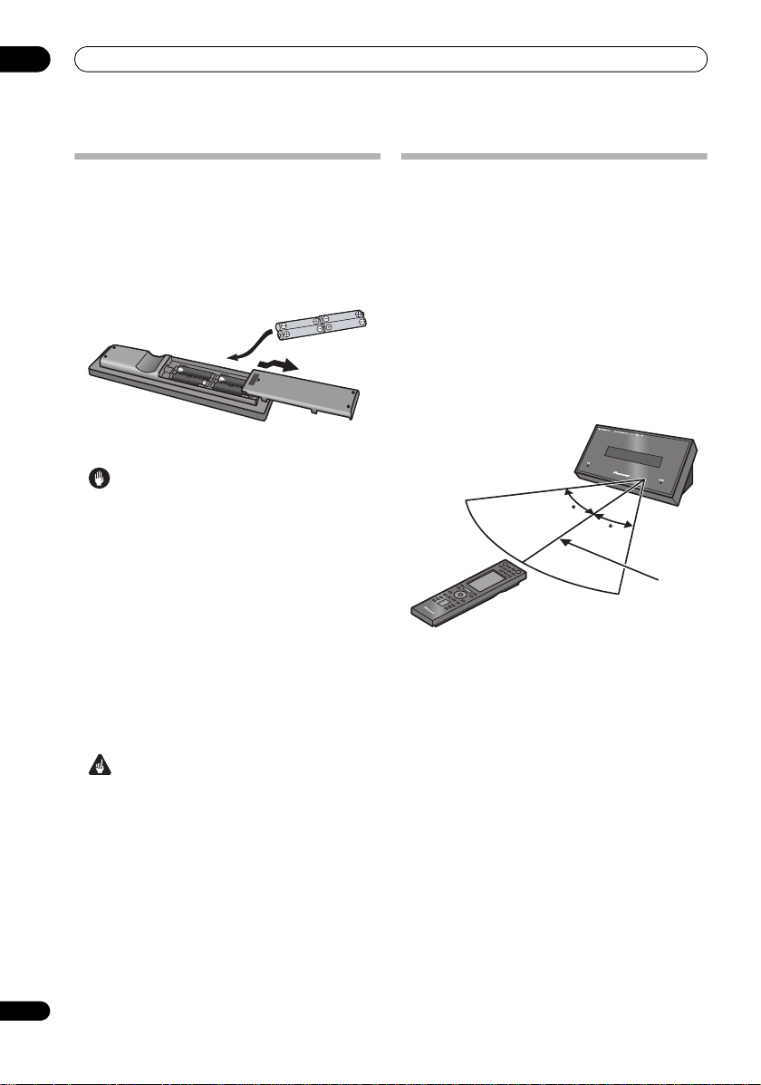
Putting the batteries in the remote
control
1 Open the battery compartment cover on the
back of the remote control.
2 Insert four AA/LR6 alkaline batteries into the
battery compartment following the indications
(,) inside the compartment.
3 Close the cover.
Caution
Incorrect use of batteries can result in hazards such
as leakage and bursting. Please observe the
following:
• Don’t mix new and old batteries together.
• Don’t use different kinds of battery together —
although they may look similar, different batteries
may have different voltages.
• Make sure that the plus and minus ends of each
battery match the indications in the battery
compartment.
• Remove batteries from equipment that isn’t going to
be used for a month or more.
• When disposing of used batteries, please comply with
governmental regulations or environmental public
instruction’s rules that apply in your country /area.
Using the remote control
Please keep in mind the following w hen using the remote
control:
• Make sure that there are no obstacles between the
remote and the remote sensor on the unit.
• Remote operation may become unreliable if strong
sunlight or fluorescent light is shining on the unit’s
remote sensor.
• Remote controllers for different devices can interfere
with each other. Avoid using remotes for other
equipment located close to this unit.
• Replace the batteries when you notice a fall off in the
operating range of the remote.
• Use within the operating range in front of the remote
control sensor on the display unit, as shown.
30
30
7 m
26
En
WARNING
• Do not use or store batteries in direct sunlight or
other excessively hot place, such as inside a car or
near a heater. This can cause batteries to leak,
overheat, explode or catch fire. It can also reduce the
life or performance of batteries.
Page 27
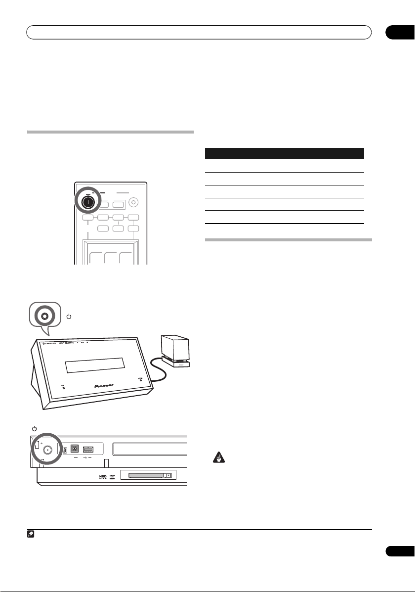
Before you start
STANDBY/ON
STANDBY/ON
HDD/DVD recorder
Display unit
Receiver
subwoofer
Note
Chapter 4
Before you start
Switching on
When the remote control’s SYSTEM ON button is
pressed, the power of both the receiver subwoofer and
HDD/DVD recorder turns on.
ON
SYSTEM
SYSTEM
TV
OFF
FM / AM
ON
INPUT
HDMI 1 HDMI 2 HDMI 3
DVR BD DVD TV
INPUT
SELECT
The table below shows what needs to be switched on for
various system functions:
Function
Display unit
HDD/DVD recorder
DVD playback On On
CD playback On On
HDD playback On On
Radio On Off
Timer recording Off On
04
SYSTEM
ADV.
SURR
F.S .
SURR
SURR
The HDD/DVD recorder and receiver subwoofer have
separate power switches. The power switch for the
receiver subwoofer is located on the display unit.
Setting up
After connecting and installing the HDD/DVD recorder
and receiver subwoofer, complete the steps below to set
the system up for use.
HDD/DVD recorder
• Set the date and time, TV channel tuning and the type
of TV in the Setup Navigator (page 68).
Receiver subwoofer
• Complete the Auto MCACC setup to optimize the
surround sound (see below).
Using the Auto MCACC setup for optimal
surround sound
The Multichannel Acoustic Calibration (MCACC) system
measures the acoustic characteristics of your listening
area, taking into account ambient noise, and testing for
channel delay and channel level. After you have set up
the microphone provided, the system uses the
STANDBY/ON
DV IN
USB
1 You only need to use the Auto MCACC setup once (unless you change the placement of your speakers or your room layout).
information from a series of test tones to measure
standing wave and reverb, optimizing the speaker
settings and equalization (MCACC Effect) for your
particular room.
1
Important
• The test tones used for Auto MCACC setup are loud;
however, do not turn the volume down during setup
as this may result in a sub-optimal setup.
• Make sure the microphone and speakers are not
moved during the MCACC setup.
27
En
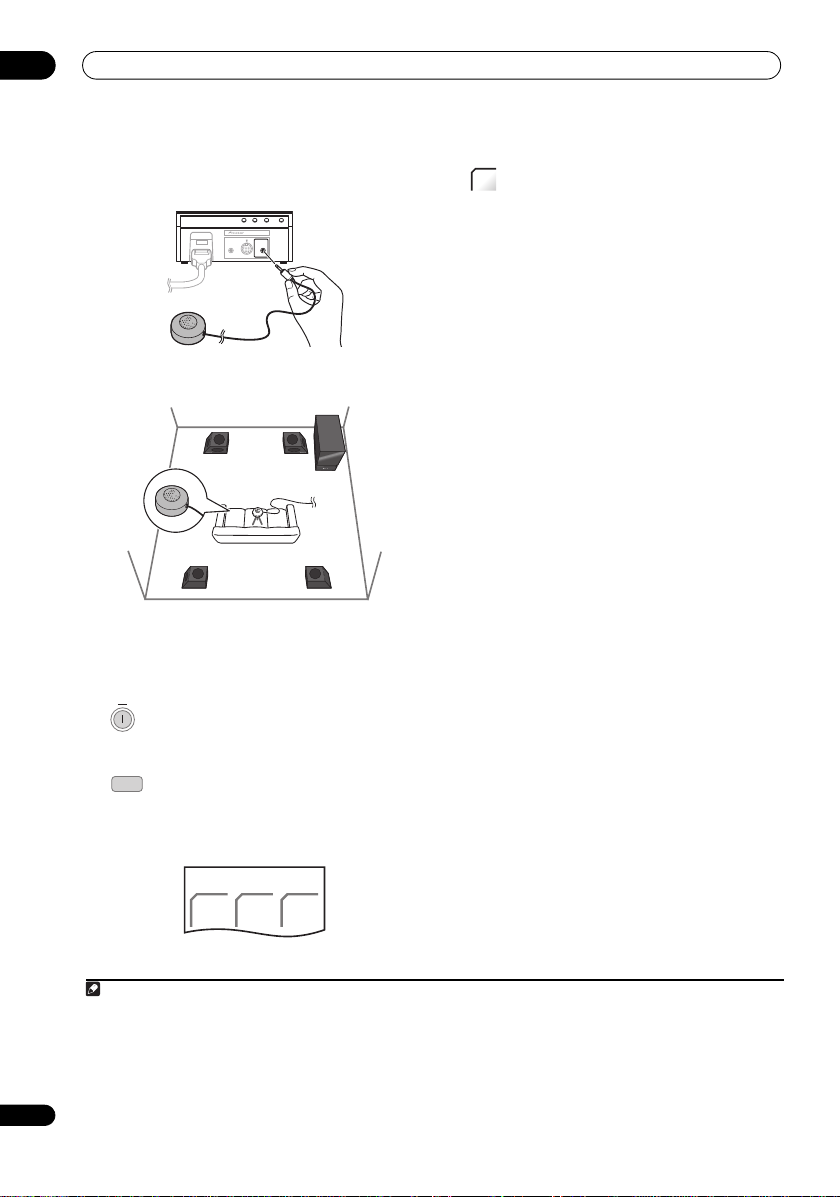
Page 28
04
F.AUDIO
DISPLAY UNIT
iPod
MCACC
SETUP MIC
SYSTEM
ON
L
Note
Before you start
1 Connect the microphone to the MCACC SETUP
MIC jack on back of the display unit.
2 Place the microphone at your normal listening
position.
Place it about ear height, and make sure it is level by
using a table or chair.
Make sure there are no obstacles between the speakers
and the microphone.
3
If the receiver subwoofer is off, press
SYSTEM ON to turn the power on.
SYSTEM
4 Press SYSTEM CONTROL to set the remote
CONTRO
control to receiver control mode.
Make sure that the LCD displays the SYSTEM screen, as
shown below.
MCACC
5 Press MCACC.
Try to be as quiet as possible after pressing MCACC. The
volume increases automatically and the system outputs
a series of test tones.
• To cancel Auto MCACC setup before it has finished,
press MCACC. The unit will continue to use the
previous settings.
• If the ambient noise level is too high, Noisy! blinks in
the display for five seconds. To exit and check the
noise levels
1
, press MCACC, or to try again, press
ENTER when Retry shows in the display.
•If you see an Error MIC! or Error Speaker! message
in the display, there may be a problem with your mic
or the speaker connections. To try again, press
2
ENTER
.
When the MCACC setup is complete, the volume level
returns to normal, Complete
MCACC Effect is activated.
3
shows in the display, and
4
• Be sure to disconnect the microphone from this unit
upon completion of the Auto MCACC setup.
28
En
SYSTEM
ADV.
SURR
F.S .
SURR
SURR
1 • If the room environment is not optimal for the Auto MCACC setup (too much ambient noise, echo off the walls, obstacles blocking the
speakers from the microphone) the final settings may be incorrect. Check for household appliances (air conditioner, fridge, fan, etc.), that may
be affecting the environment and switch them off if necessary.
• Some older TVs may interfere with the operation of the mic. If this seems to be happening, switch off the TV during Auto MCACC setup.
2 If this doesn’t wor k, press MCACC, turn off the power, and check the problem indicated by the Error message, then try the Auto MCACC set up
again.
3If Complete doesn’t appear, it is likely an error occurred during the setup. Please check all connections and try again.
4 See Listening with MCACC Effect on page 34 to switch on/off MCACC Effect.
Page 29
Before you start
L
DVR
HDMI 1
TV
FM/AM
Basic operation
This manual is split into two parts, one covering using the
receiver subwoofer, the other using the HDD/DVD
recorder. Below are some common operations and
where to find them explained in this manual.
Operating the remote control
The supplied remote control can control not only the
receiver subwoofer and HDD/DVD recorder, but also
other Pioneer products such as Blu-ray disc players, DVD
players, and Flat Screen TVs.
To operate these components, orient the remote control
toward the display unit.
Operating the receiver subwoofer
SYSTEM
• Press SYSTEM CONTROL to display the
CONTRO
SYSTEM screen.
The SYSTEM screen is shown on the remote control’s
LCD screen, and the remote is switched to SYSTEM
mode.
SYSTEM
ADV.
SURR
F.S .
SURR
SURR
Operating the HDD/DVD recorder
• Press DVR (HDMI 1) to display the HDD/
DVR screen.
The HDD/DVR screen is shown on the remote control’s
LCD screen, and the remote is switched to HDD/DVD
recorder control mode.
Choosing and operating a source component
HDMI 1 HDMI 2 HDMI 3
DVR BD DVD
•
Press to cycle through connected components.
The selected component changes, and the LCD screen
on the remote control changes to that of the appropriate
component.
• To select input for Digital 1, Digital 2, Analog, Front
Audio In, or iPod, press the SYSTEM CONTROL
button to set the remote control to th e SYSTEM mode,
then press the LINE button until the desired input
function is shown on the display unit.
Note
• To temporarily control the receiver while listening to
audio from a connected component on this unit,
press SYSTEM CONTROL. The selected input will not
change, and the remote changes to SYSTEM mode.
To return to the previous operating mode, press
SYSTEM CONTROL once more.
Using the LCD touch screen
Depending on the type of connected component you are
operating (such as an HDD/DVD recorder), there may be
multiple pages of information for the LCD touch screen.
When the component you would like to control is not
displayed, press PAGE to scroll to the page where the
component you would like to control is located.
• The LCD touch screen’s illumination turns on and off
each time the LIGHT button is pressed. The
illumination automatically turns off after 30 seconds.
The LCD touch screen’s display turns off after one
minute. To have the display shown once again, either
touch the LCD or press a button on the remote
control.
04
HDD/DVR 1/3
JUKE
HDD/
DVD
BOX
P.LIVE
TV
29
En
Page 30
04
ON
TV
OPEN/
CLOSE
SYSTEM
VOL
SYSTEM
VOL
TV
SYSTEM
VOL
-
+
TUNE
SYSTEM
VOL
Before you start
Watching a DVD
Remember that when using the remote to control the
supplied HDD/DVD recorder, you should point the
remote towards the display unit, not the recorder itself.
1 Switches on the system.
HDMI 1
DVR
2 Set the remote control to HDD/DVR mode.
Press DVR (HDMI 1) to set the remote control to HDD/
DVR control mode in order to operate the HDD/DVD
recorder.
3 Switch on your TV.
Turn on your TV and make sure that it is set to the HDMI
video input.
HDD/
DVD
4 Press to select DVD.
5 Press on the HDD/DVD recorder to open
the disc tray.
6 Load a disc.
Load a disc with the label side facing up, using the disc
tray guide to align the disc (if you’re loading a doublesided DVD disc, load it with the side you want to play
face-down).
Listening to a CD
ON
1 Switches on the system.
HDMI 1
DVR
2 Set the remote control to HDD/DVR mode.
Press DVR (HDMI 1) to set the remote control to HDD/
DVR control mode in order to operate the HDD/DVD
recorder.
HDD/
3 Press to select DVD.
DVD
4 Load a CD and start playback (page 104).
5 Adjust the volume.
Watching a title recorded on the HDD
ON
1 Switches on the system.
HDMI 1
DVR
2 Set the remote control to HDD/DVR mode.
Press DVR (HDMI 1) to set the remote control to HDD/
DVR control mode in order to operate the HDD/DVD
recorder.
3 Switch on your TV.
HDD/
4 Press to select HDD.
DVD
5 Start playback of the HDD title (page 104).
7 Press to start playback.
Press to stop playback.
You can resume playback from the same
point by pressing . (Press again to
cancel the resume function.)
Pauses playback, or restarts playback
when paused.
Press to start scanning. Press repeatedly
to increase the scanning speed.
See Basic playback on page 103 for more on playing
6 Adjust the volume.
Listening to the radio
ON
1 Switches on the system.
FM/AM
2 Set the remote control to FM/AM mode.
3 Tune to a station (page 35).
The LCD screen changes to that for the radio, and you
can then operate the desired component.
discs.
4 Adjust the volume.
30
En
8 Adjust the volume.
Page 31

Listening to your system
L
Note
DIRECT
Chapter 5
Listening to your system
05
Important
SYSTEM
CONTRO
• Press to set the remote control to receiver
control mode in order to operate the receiver
subwoofer (make sure that the LCD displays the
SYSTEM screen, as shown below).
SYSTEM
ADV.
SURR
F.S .
SURR
SURR
Effective Sound (for optimum sound)
With the uniquely shaped high-quality speakers supplied
with this unit, the Effective Sound mode enables the
following Pioneer exclusive audio technologies designed
to maximize the real experience of sound originally
inherent in movies and music.
Turn on the Effective Sound mode under normal
circumstances to maximize the capabilities of this unit.
• Dialogue Enhancement
Clarifies dialogue in movies to make it stand out from
other background sounds.
• Dynamic Range Compression
Resuscitates detailed sound susceptible to ambient
noise to create an acoustic environment where you
feel as if you are right in the action.
• Original Channel Balance & Channel Mix
Since the orientation of the supplied speaker units is
uniquely designed, channels are mixed down and
balanced in a special manner. Also, the optimum
balance is automatically achieved according to the
contents being played back.
• Frequency Characteristic Correction
Realizes the playback characteristic optimized for
long hours of listening in addition to the added
features of the supplied speaker units.
• Stereo Playback in Surround
Outputs audio from the surround speakers while
directing vocal sound to the front channels. You can
play back stereo sources like CDs in seamless,
comfortable surround sound.
This effect is available when you play back stereo
sources in the Auto listening mode (see below).
The Effective sound mode can be turned off (activating
Direct mode) by doing the following:
• Press to switch to Direct Sound.
Press this button to switch between Effective Sound and
Direct Sound.
• When Direct Sound is selected, the DIRECT indicator
lights.
Auto listening mode
The Auto listening mode is the simplest way to listen to
any source as it was mastered: the output from the
speakers mirrors the channels in the source material.
If you set up the system for Front surround (page 6), the
Front Stage Surround modes will give the best results
(see page 33).
SURR
• Press to select the Auto listening mode.
Listening in surround sound
You can listen to stereo or multichannel sources in
surround sound. Surround sound is generated from
stereo sources using one of the Dolby Pro Logic or DTS
Neo:6 decoding modes.
If you set up the system for Front surround (page 6), the
Front Stage Surround modes will give the best results
(see page 33).
SURR
• Press repeatedly to select a listening mode.
The choices that appear in the display will vary according
to the type of source that’s playing.
1
2
1 After the surround back signals of the 6.1/7.1-channel audio represented by DTS-ES are properly decoded, the original virtual surround back
function outputs the surround back signals in combination with surround signals.
2 You cannot select a mode other than Auto and Stereo while playing back DTS-HD, DTS-Express, or Dolby TrueHD (176.4 kHz/192 kHz). Also,
you cannot select DTS Neo:6 for Dolby Digital Plus or Dolby TrueHD (below 96 kHz).
31
En
Page 32

05
Note
SOUND
ENTER
SOUND
ENTER
ENTER
ADV
SURR
Listening to your system
With two channel sources, you can select from:
• Auto – Auto listening mode (see page 31)
• 2PL II Movie (Dolby Pro Logic II Movie) – 5.1
channel surround sound, especially suited to movie
sources
• 2PL II Music (Dolby Pro Logic II Music) – 5.1
channel surround sound, especially suited to music
sources; see Dolby Pro Logic II Music settings below
• 2PL II Game (Dolby Pro Logic II Game) – 5.1
channel surround sound, especially suited to video
games
• 2Pro Logic (Dolby Pro Logic) – 4.1 channel
surround sound for use with any two-channel source
• Neo:6 Cinema – 6.1 channel sound, especially suited
to movie sources
• Neo:6 Music –
music sources; see
6.1 channel sound, especially suited to
Center image setting below
• Stereo – See Listening in stereo on page 33.
With multichannel sources, you can select (according to
format):
• Auto – Auto listening mode (see page 31)
• StandardDecode – Listening in Dolby Digital or DTS
surround decoding. Plays back multichannel
sources like Dolby Digital, DTS, and multichannel
PCM with the most standard decoder.
• Stereo – See Listening in stereo on page 33.
Dolby Pro Logic II Music settings
When listening in Dolby Pro Logic II Music mode (see
above), there are three settings you can adjust: Center
Width, Dimension, and Panorama.
1 Press when Dolby Pro Logic II Music mode is
active.
ENTER
2 Select ‘Center Width’, ‘Dimension’ or
‘Panorama’ then press ENTER.
• Center Width
speakers by spreading the center channel between
the front right and left speakers, making it sound
wider (higher settings) or narrower (lower settings).
• Dimension – Adjusts the depth of the surround
sound balance from front to back, making the sound
more distant (minus settings), or more forward
(positive settings).
1
– Provides a better blend of the front
•
Panorama
– Extends the front stereo image to include
the surround speakers for a ‘wraparound’ effect.
3 Adjust the setting, then press ENTER to
confirm.
Center image setting
When listening to two channel sources in Neo:6 Music
mode (see page 31), you can also adjust the center image
effect.
Adjusts the center image to create a wider stereo effect
with vocals.
2
1 Press when Neo:6 Music mode is active.
2 Select ‘Center Image’ then press ENTER.
3 Adjust the setting, then press ENTER to
confirm.
• Adjust the effect from 0 (all center channel sent to
front right and left speakers) to 10 (center channel
sent to the center speaker only).
Using Advanced Surround
The Advanced Surround effects can be used with any
multichannel or stereo source for a variety of additional
surround sound effects. These modes are designed to
provide optimum listening effect when using the
Standard surround setup described on page 6.
• Press to select an Advanced Surround mode.
The ADV.SURR. indicator lights when one of these
modes is chosen. You cannot switch between modes for
some audio streams.
Press repeatedly to select:
• Action – Designed for action movies with dynamic
soundtracks
• Drama – Designed for movies with lots of dialog
• Sci-Fi – Designed for science fiction with lots of
special effects
• Mono Film – Creates surround sound from mono
soundtracks
3
32
En
1 As this product uses a dual center speaker system, you should normally use the C.Width 3 setting.
2 As this product uses a dual center speaker system, you should normally use the C.Image 3 setting.
3 You cannot use this function for the following audio streams:
• Dolby TrueHD: over 88.2 kHz
• DTS-HD: over 88.2 kHz or with the channel format of 2/0
• DTS-Express: with the channel format of 2/0
Page 33

Listening to your system
Note
F.S .
SURR
SURR
• Ent.Show – Suitable for musical sources
• Expanded – Creates an extra wide stereo field
• TV Surround – Provides surround sound for both
mono and stereo TV sources
• Advanced Game – Suitable for video games
• Sports – Suitable for sports programs
• Classical – Gives a large concert hall-type sound
• Rock/Pop – Creates a live concert sound for rock
and/or pop music
• Unplugged – Suitable for acoustic music sources
• Ext.Stereo – Gives multichannel sound to a stereo
source, using all of your speakers
Using Front Stage Surround Advance
The Front Stage Surround Advance modes are effective
when you are using the Front surround speaker setup as
described on page 6.
• Press to select a Front Stage Surround
Advance mode.
The F.S.SURR indicator lights.
Press repeatedly to select Focus 5.1ch, Wide 5.1ch or
Extra Power. You cannot select a mode other than Extra
Power for some audio streams.
1
• Focus 5.1ch – Use to provide a rich surround sound
effect directed to the center area where the left and
right speakers sound projection converges.
• Wide 5.1ch – Use to provide a surround sound effect
to a wider area than Focus 5.1ch mode.
• Extra Power –
multi-channel sources, down-mixed stereo sound)
from the surround speakers for powerful stereo effect.
Outputs stereo sound (in the case of
Listening in stereo
You can listen to any source — stereo or multichannel —
in stereo. When playing a multichannel source, all
channels are downmixed to the front left/right speakers
and the subwoofer.
• Press repeatedly until STEREO shows in the
display.
Genre Sync Mode
Only when you have this unit connected to the supplied
HDD/DVD recorder and are using the HDMI Control
function, you can make use of the Genre Sync Mode to
have the listening mode automatically change to that
which best matches the genre of the contents playing
from the recorder.
2
•Set the HDMI Mode to AMP Mode (page 43).
GENRE
• Press when listening to media contents
from a recorder.
The most appropriate listening mode is selected and
shown in the display. When the related genre could not
be determined, No Genre or Can’t use may be displayed
and the listening mode remains unchanged.
Tip
• Mainly used with Jukebox and MP3 sources.
• To use this function, you must have an HDMI Controlcompatible Pioneer HDD/DVD record er connected via
HDMI, and have the HDMI Control function set to On.
Using the Sound Retriever
When audio data is removed during the MP3 or WMA
compression process, sound quality often suffers from
an uneven sound image. The Sound Retriever feature
employs new DSP technology that helps bring CD quality
sound back to compressed two channel audio by
restoring sound pressure and smoothing jagged artifacts
left over after compression.
Tip
• This feature is effective when used together with the
Jukebox function of the HDD/DVD recorder.
SOUND
RTRV
• Press while listening to a stereo source
Press repeatedly to switch between:
• Retriever On — Switches the Sound Retriever on.
• Retriever Off — Switches the Sound Retriever off.
3
.
05
1 You cannot use this function for the following audio streams:
• Dolby TrueHD: over 88.2 kHz
• DTS-HD: over 88.2 kHz or with the channel format of 2/0
• DTS-Express: with the channel format of 2/0
2 This function is available only for a Pioneer HDMI Control-compatible HDD/DVD recorder.
3 This setting cannot be used with multichannel sources. Also, in case of SACD, DTS-HD, DTS-Express, Dolby TrueHD, Dolby Digital Plus, and
PCM (192 kHz/176.4 kHz), even stereo sources cannot be used.
33
En
Page 34

05
Note
SOUND
ENTER
SOUND
SOUND
ENTER
ENTER
ENTER
SOUND
ENTER
ENTER
Listening to your system
Listening with MCACC Effect
Listen to sound using the corrected acoustic field
settings obtained by MCACC.
1 Press to open the sound menu.
2 Select ‘MCACC Effect’ then press ENTER.
ENTER
3 Switch ‘MCACC On’ or ‘MCACC Off’ then
press ENTER to confirm.
• When MCACC Effect is off, equalization, channel
delay, channel level and standing wave are set to off.
• When MCACC Effect is off, the channel delay and
channel level can be adjusted manually and the
settings stored separately from when MCACC Effect
is on.
• MCACC Effect is set to on automatically after Auto
MCACC setup is used.
Using Midnight, Loudness and Quiet
listening modes
The Midnight listening feature allows you to hear
effective surround sound of movies at low volume levels.
The Loudness listening feature can be used to get good
bass and treble from music sources at low volume levels.
The Quiet listening feature reduces excessive bass or
treble in a sound source.
1 Press to open the sound menu.
Adjusting the bass and treble
Use the bass and treble controls to adjust the overall tone.
1 Press to open the sound menu.
2 Select ‘Tone’ then press ENTER.
3 S
elect
‘Bass/Treble’ then press ENTER.
1
• Selecting Bass/Treble cancels the Midnight,
Loudness and Quiet listening modes. These modes
cannot be used at the same time.
4 Use the / buttons to select ‘Bass’ or
‘Treble’; use the / buttons to adjust the sound
then press ENTER to confirm.
• Bass and Treble can be adjusted from -6dB to +6dB.
• When the Bass or Treble is set to something other
than 0dB, the TONE indicator lights.
Adjusting sound delay
Some monitors have a slight delay when showing video,
so the soundtrack will be slightly out of sync with the
picture. By adding a bit of delay, you can adjust the sound
to match the presentation of the video.
There are a total of 60 steps (levels) that you can adjust,
with a total range of 200 msec.
1 Press to open the sound menu.
34
En
ENTER
2 Select ‘Tone’ then press ENTER.
ENTER
3 S
then press ENTER to confirm.
elect ‘
Midnight
’, ‘
Loudness
2
’ or ‘
1
Quiet’
• To cancel the Midnight, Loudness or Quiet listening
modes, select Bass/Treble.
1 While playing b ack DTS-HD (over 88.2 kHz) or Dolby TrueHD (over 88.2 kHz) audio streams, you cannot select Tone if a mode o ther than Bass/
Treble is selected.
2 W hile pla ying ba ck DTS-H D (over 8 8.2 kHz ) or Dolb y TrueHD (over 88.2 kHz) audio streams, you cannot se lect a mode other than Bass/Treble.
2 Select ‘Sound Delay’ then press ENTER.
3 Select the length of the delay in sound,
then press ENTER to confirm.
• This option is deactivated and not displayed if you
have AutoDelay set to On i n HDMI Setu p (s ee Setting
the Auto Delay on page 43).
Page 35

Listening to the radio
FM/AM
FM/AM
123
FM/AM
SETUP
ENTER
ENTER
ENTER
ENTER
ENTER
ENTER
ENTER
Chapter 6
Listening to the radio
06
Important
• To listen to the radio, press the FM/AM button
to set the remote control to FM/AM control mode. The
LCD screen on the remote control changes to the
FM/AM screen.
Listening to the radio
The tuner can receive both FM and AM broadcasts, and
lets you memorize your favorite stations so you don’t have
to manually tune in every time you want to listen.
1
select the FM or AM band.
The display shows the band and frequency.
2 Tune to a frequency.
There are three tuning modes — manual, auto, and high-
speed:
Improving poor FM reception
If you’re listening to an FM station in stereo but the
reception is weak, you can improve the sound quality by
switching to mono.
1 Press after tuning to an FM radio station.
2 Select ‘Tuner Setup’ then press ENTER.
Switch to the tuner, then press repeatedly to
TUNE
-
+
• Manual tuning – Press TUNE +/– repeatedly to
change the displayed frequency.
• Auto tuning – Press and hold TUNE +/– until the
frequency display starts to move, then release. The
tuner will stop on the next station it finds. Repeat to
keep searching.
• High-speed tuning – Press and hold TUNE +/– until
the frequency display starts to move rapidly. Keep the
button held down until you reach the frequency you
want. If necessary, fine tune the frequency using the
manual tuning method.
3 Choose ‘FM Auto/Mono’ then press
ENTER.
4 Select ‘FM Mono’ then press ENTER.
The mono indicator ( ) lights when the tuner is in mono
reception mode.
Select FM Auto above to switch back to auto-stereo
mode (the stereo indicator ( ) lights when receiving a
stereo broadcast).
Improving poor AM sound
The simplest way to improve the sound quality of AM
radio is to make sure that the TV in the room is switched
off. Also try changing the position and direction of the
AM loop antenna.
Changing the noise cut mode
If you find that the AM sound quality is bad even after
trying the above, you may be able to improve it using a
different noise cut mode. Just choose the one that
sounds best.
SETUP
1 Press after tuning to an AM radio station.
2 Select ‘Tuner Setup’ then press ENTER.
3
4
C
hoose ‘Noise Cut’ then press ENTER.
S
elect a Noise cut mode (1, 2 or 3) then
press ENTER.
Memorizing stations
You can save up to 30 station presets so that you always
have easy access to your favorite stations without having
to tune in manually each time.
1 Tune to an FM or AM radio station.
Select mono or auto-stereo reception (FM) or the Noise
Cut mode (AM) as necessary. These settings are saved
along with the preset.
SETUP
2
Press
SETUP
.
3
Select ‘Tuner Setup’ then press ENTER.
35
En
Page 36

06
Note
ENTER
-
+
ST
FM/AM
DISPLAY
ENTER
Listening to the radio
4 Choose ‘ST.Memory’ then press ENTER.
ENTER
5 Select the station preset you want then
press ENTER.
Listening to station presets
1 Make sure the tuner function is selected.
2 Select a station preset.
• Alternatively, use the number buttons to select a
preset directly.
Displaying RDS information
You can display the different types of RDS information
2
available.
DISPLAY
• Display the RDS information.
Each press changes the display as follows:
•Radio Text (RT) – Messages sent by the radio station.
For example, a talk radio station may provide a phone
number as RT.
• Program Service Name (PS) – The name of the radio
station.
•Program Type (PTY) – This indicates the kind of
program currently being broadcast.
• Search – PTY search (see below)
• Current tuner frequency
36
En
Using RDS
Radio Data System (RDS) is a system used by most FM
radio stations to provide listeners with various kinds of
information — the name of the station and the kind of
show they’re broadcasting, for example.
One feature of RDS is that you can search by type of
program. For example, you can search for a station that’s
broadcasting a show with the program type, Jazz.
You can search the following program types:
News – News
Affairs – Current Affairs
Info
– General Information
Sport – Sport
Educate – Educational
Drama – Radio plays, etc.
Culture – National or regional
culture, theater, etc.
Science – Science and
technology
Varied – Usually talk-based
material, such as quiz shows or
interviews
Pop M – Pop music
Rock M – Rock music
Easy M – Easy listening
Light M – ‘Light’ classical music
Classics – ‘Serious’ classical
music
Other M – Music not fitting
above categories
Weather – Weather reports
1 In addition, there are three other program types, Test, Alarm, and No Type. Alarm and Test are used for emergency announcements. You
can’t search for these, but the tuner will switch automatically to this RDS broadcast signal. No Type appears when a program type cannot be
found.
2 • If any noise is picked up while displaying the RT scroll, some characters may be displayed incorrectly.
• If you see No Radio Text Data in the RT display, it means no RT data is sent from the broadcast station. The display will automatically switch
to the PS data display (if no PS data, the frequency is displayed).
• In the PTY display, No Data or No Type may be shown. In this case, the PS display is shown after a few seconds.
3 RDS is only possible in the FM band.
Finance – Stock market reports,
commerce, trading, etc.
Children – Programs for children
Social – Social affairs
Religion – Programs concerning
religion
Phone In – Public expressing
their views by phone
Travel – Holiday-type travel
rather than traffic
announcements
Leisure – Leisure interests and
hobbies
Jazz – Jazz
Country
Nation M – Popular music in a
language other than English
Oldies – Popular music from the
’50s and ’60s
Folk M – Folk music
Document – Documentary
1
– Country music
Searching for RDS programs
You can search for a program type listed above.
1 Press to select the FM band.
2 Press repeatedly until ‘Search’ appears in
the display.
3 Select the program type you want to hear.
4 Start the search.
The system searches the station presets for a match. If it
finds one, searching stops for five sec.
5 If you want to keep listening to the station, press
ENTER within the five seconds.
If you don’t press ENTER, searching resumes.
3
Page 37

Surround sound settings
Note
L
ENTER
ENTER
ENTER
ENTER
ENTER
Chapter 7
Surround sound settings
SETUP
Important
SYSTEM
CONTRO
• Press to set the remote control to receiver
control mode in order to operate the receiver
subwoofer (make sure that the LCD displays the
SYSTEM screen, as shown below).
SYSTEM
ADV.
SURR
F.S .
SURR
SURR
1 Press SETUP.
2 Select ‘Sound Setup’ then press ENTER.
3 Select ‘ChannelLevel’, then press ENTER.
4 Use the / buttons to select a channel
or the / buttons to adjust the level of that
channel.
• You can adjust the level of each channel by ±10 dB.
07
2
Using the Sound Setup menu
From the Sound Setup menu you can access all the
surround sound settings of the system.
5 Press once when you’re finished.
• If you use the Auto MCACC feature again, it will
overwrite the settings you have made here.
During setup, the speakers are represented by the
following letters:
• L – Front left speaker
• C – Center speaker
• R – Front right speaker
• SR – Surround right speaker
• SL – Surround left speaker
• SW – Subwoofer
Channel level setting
1
The Auto MCACC feature (see page 27) should give you
Speaker distance setting
The Auto MCACC feature (see page 27) should give you
the best surround sound setup. However you may find
that by further adjustment of the speaker distance
settings you can improve the surround sound in your
listening room.
Set the distance of each speaker from your normal
listening position.
ENTER
SETUP
1 Open the ‘Sound Setup’ menu.
1
the best surround sound setup. However you may find
that by further adjustment of the channel levels you can
improve the surround sound in your listening room.
2 Select ‘Distance’ then press ENTER.
This method of setting the channel levels allows you to
listen to a source and adjust the levels of each playback
channel.
A further method of setting the channel levels is to use
the test tone method. See Adjusting the channel levels
3 Use the / buttons to select a speaker
or the / buttons to adjust the distance.
Each speaker can be adjusted from 0.1 m to 9.0 m.
using the test tone on page 39 for more on this.
4 Press ENTER when you’re finished.
• If you use the Auto MCACC feature again, it will
overwrite the settings you have made here.
1 When this function is set while MCACC Effect is on, the value for the same function adjusted with the Auto MCACC feature is overwritten.
When MCACC Effect is off, the value set here is applied, regardless of the value adjusted with the Auto MCACC feature. (The Auto MCACC
setting is not overwritten.)
2 The range of adjustment is limited when the volume level is set over 51.
37
En
Page 38

07
Note
SETUP
ENTER
SETUP
ENTER
ENTER
ENTER
Surround sound settings
Dynamic Range Control
1
When watching Dolby Digital or DTS material at low
volume, low level sounds — including some of the dialog
— can be difficult to hear properly. Using one of the
Dynamic Range Control (DRC) settings can help by
bringing up the low level sounds, while controlling high
level peaks.
Dynamic Range Control works only with Dolby Digital
soundtracks and some DTS soundtracks.
1 Open the ‘Sound Setup’ menu.
ENTER
2 Select ‘D.R.C.’, then press ENTER.
3 Select a setting.
Select one of the following:
• D.R.C. Auto – Only available for Dolby TrueHD
signals. Select D.R.C. High or D.R.C. Mid for signals
other than Dolby TrueHD.
• D.R.C. High – Dynamic range is reduced (loud
sounds are reduced in volume while quieter sounds
are increased)
• D.R.C. Mid – Mid setting
• D.R.C. Off – No dynamic range adjustment (use
when listening at higher volume)
ENTER
4 Press to exit.
Dual mono setting
2
Specifies how dual mono encoded Dolby Digital
soundtracks should be played. You can also use this
setting to switch the audio channel on DVD-RW discs
recorded with bilingual audio.
1 Open the ‘Sound Setup’ menu.
2 Select ‘Dual Mono’, then press ENTER.
3 Select a setting.
Select one of the following:
• CH1 Mono – Only channel 1 is played
• CH2 Mono – Only channel 2 is played
• CH1/CH2 – Both channels are played through the
front speakers
4 Press to exit.
38
En
1 This setting is effective for the speaker output. A similar adjustment feature is available on the HDD/DVD recorder — see Audio DRC on
page 156.
2 This setting is effective for the speaker output. A similar adjustment feature is available on the HDD/DVD recorder — see Switching audio
channels on page 111.
Page 39

Surround sound settings
Note
SETUP
ENTER
ENTER
ENTER
SETUP
ENTER
ENTER
ENTER
ENTER
Using the Virtual Surround Back mode
This mode allows you to hear a virtual surround back
channel through your surround speakers. You can
choose to listen to sources with no surround back
channel information, or if the material sounds better in
the format (for example, 5.1) for which it was originally
encoded, you can have the receiver only apply this effect
to 6.1 encoded sources like Dolby Digital EX or DTS-ES.
1 Open the ‘Sound Setup’ menu.
2 Select ‘Virtual SB’, then press ENTER.
Adjusting the channel levels using
the test tone
If you prefer, you can set the channel levels using a test
tone as a reference, rather than playing a source (see
Channel level setting on page 37). A test tone is played
through each speaker in turn, allowing you to adjust the
1
level as it plays.
You can also adjust the channel levels for surround
sound using test tone.
TEST
TONE
1 Carry out tone testing.
The test tone is output from each speaker in turn.
Adjust the volume level below 50.
07
3 Select a setting.
Select one of the following:
• Vir.SB On – Virtual Surround Back is always used (for
example, on 5.1 encoded material)
• Vir.SB Auto – Virtual Surround Back is automatically
applied to 6.1 encoded sources (for example, Dolby
Digital EX or DTS-ES), DTS Neo:6 or Advanced
Surround mode
• Vir.SB Off – Virtual Surround Back mode is switched
off
4 Press to exit.
LFE Attenuate
Some Dolby Digital and DTS audio sources include ultralow bass tones.
Set the LFE attenuator as necessary to prevent the ultralow bass tones from distorting the sound from the
speakers.
The LFE is not limited when set to 0dB, which is the
recommended value. When set to -5dB, -10dB, -15dB or
-20dB, the LFE is limited by the respective degree. When
Off is selected, no sound is output from the LFE channel.
1 Open the ‘Sound Setup’ menu.
2 Select ‘LFE ATT’, then press ENTER.
3 Adjust the setting then press ENTER to
confirm.
2 Adjust the channel level of a tune while it
is playing.
The aim is to adjust the levels so that you hear the test
tone at the same volume from each speaker. You can
adjust the level of each channel by ±10 dB.
• You can adjust the overall volume of test tone output
using the VOL +/– buttons (this does not affect the
channel level settings).
• Because of the ultra low frequencies the subwoofer
produces, it may sound quieter than it really is. We
suggest adjusting the subwoofer level while listening
to a source. See the method described in Channel
level setting on page 37.
3 Press to exit test tone setup once you have
finished.
• If you use the Auto MCACC feature again, it will
overwrite the settings you have made here.
1 Depending on the input signal and the listening mode, the Virtual Surround Back mode may not be effective.
39
En
Page 40

08
SYSTEM
CONTROL
SYSTEM
SURR
ADV.
SURR
F.S .
SURR
AM LOOP
ANTENNA
R
L
ANALOG
AUDIO IN
OPTICAL
IN 1
IN 2
DIGITAL
From digital audio
output (optical)
or
From Audio output
TV
Side panel
Receiver subwoofer
SETUP
ENTER
ENTER
ENTER
Other connections
Chapter 8
Other connections
• When making or changing connections on the side
• Press to set the remote control to receiver
Using this unit for TV audio
To listen to audio from a TV, connect the TV’s audio cable
to one of the inputs on this unit.
Important
panel of this unit, be sure to switch power off and
disconnect the power cord from the wall socket.
After completing all connections, connect the power
cord to the wall socket.
control mode in order to operate the receiver
subwoofer (make sure that the LCD displays the
SYSTEM screen, as shown below).
• Connect the audio output jacks on your TV to the
audio input jacks on the receiver subwoofer.
• You can connect by either a digital or analog audio
cable. Select only one method to make connections.
• To use the HDMI Control function when you are
connected to a supported Pioneer Flat Screen TV, you
must connect via HDMI.
• When digital connections are used, it may be
necessary to adjust the digital audio output settings
on the TV. For details, consult the operating
instructions for your TV.
Audio input settings from TVs (TV Input)
To listen to audio from a Flat S cre en TV on th is de vi ce , y ou
will need to connect an audio cable other than an HDMI
cable. From this menu, set the audio input to that which
you would like to connect. Press TV on the remote
control to switch this unit to the input source selected
here. This setting is changed to the selected input and
the audio from the Flat Screen TV is output from this
device.
Select from inputs Digital 1, Digital 2 and Analog.
1 Press SETUP.
2 Select ‘System Setup’ then press ENTER.
3 Select ‘TV Input’, then press ENTER.
4 Adjust the setting then press ENTER to
confirm.
40
En
Connecting auxiliary components
You can connect both analog and digital external audio
sources to this system. Digital audio sources include
digital satellite receivers, CD recorders, etc.
We recommend using an HDMI cable to connect
sources that have HDMI terminals. For more information
see Connecting using HDMI on page 42.
Page 41

Other connections
From Audio output
R
L
ANALOG
AUDIO IN
Side panel
Receiver subwoofer
Tape player, MD, DAT, etc.
F.AUDIO
DISPLAY UNIT
iPod
MCACC
SETUP MIC
SYSTEM
F.AUDIO
Digital audio player, etc.
Display unit
From analog
audio output
Stereo mini-plug cable
08
Connecting for digital audio
This system has optical-type digital inputs. Use these to
connect external components, such as your MD or CD
recorder.
Receiver subwoofer
Side panel
IN 2
IN 1
OPTICAL
DIGITAL
From digital audio
output (optical)
MD, CD Recorder, etc.
• Connect the OPTICAL IN 2 jack on the side panel
to the optical output of an external playback
component.
These include digital components such as an MD player,
digital satellite, or a game system.
You can also use the OPTICAL IN 1 jack to connect
external components when not using it for sound input
from a TV.
Connecting an analog audio component
You can use the ANALOG AUDIO IN jacks to connect an
analog audio component, such as a tape player.
You can use the F.AUDIO input jack on the display unit
to easily playback audio from a digital audio player or PC.
Use a stereo mini-plug cable to connect a source to the
display unit.
• When you connect a cable to the F.AUDIO jack, this
unit’s input automatically switches to
Front Audio In
Connecting an iPod
You can use the iPod jack on the display unit to playback
music from an iPod. All operations can be carried out via
the iPod. Use the supplied iPod cable to connect an iPod
to this unit.
• When you connect an iPod, this unit’s input
automatically switches to iPod.
• Certain iPod models have connectors that are not
compatible with this unit.
Display unit
DISPLAY UNIT
iPod
SYSTEM
MCACC
F.AUDIO
SETUP MIC
.
iPod
iPod
Music >
Extras >
Settings >
Shuffle Songs
Backlight
R
iPod
MENU
iPod cable
iPod is a trademark of Apple Inc., registered in the U.S. and
other countries.
41
En
Page 42

08
LINE
AM LOOP
FM
UNBAL 75 Ω
ANTENNA
Side panel
Receiver subwoofer
external FM antenna
Outdoor antenna
external AM antenna
AM Loop antenna
PAL connector
(5 m to 6 m)
Indoor antenna
(vinyl-coated Wire)
Note
From HDMI output
HDMI
T IN 3 IN 2 IN 1
Receiver subwoofer
Rear panel
HDMI/DVI-equipped component
Other connections
Listening to an external audio source
To listen to audio from a connected external component
on this unit, choose its input function on the remote
control. Some Pioneer products can be controlled via this
remote.
1 If the system isn’t already on, press SYSTEM ON
to switch on.
Also make sure that the external source (TV, satellite
receiver, etc.) is switched on.
2 Select an audio input source.
Input sources are cycled through as shown below:
Digital 2
Front Audio In
The display changes to that of the selected input source.
3 If necessary, start playback of the external source.
AnalogDigital 1
iPod
About control out connections
Many Pioneer components support CONTROL
connections, by which you can use the remote controls
of any connected components by aiming them at the
sensor of just one component.
When you use a remote control, the control signal is
passed along the chain to the appropriate component.
If you choose to use this feature, you must make sure that
you also have at least one set of HDMI or analog audio
jacks connected to another component for grounding
purposes.
• Using a cable with mono mini-plugs on either
side (sold separately), connect the CONTROL IN jack
on another Pioneer component to the CONTROL OUT
jack on the receiver subwoofer.
This will allow you to control the other component by
pointing its remote at the display unit supplied with this
receiver subwoofer.
Connecting external antennas
For an external AM antenna, use 5 to 6 meters of vinylinsulated wire and set up either indoors or outdoors.
Leave the loop antenna connected.
For an external FM antenna, use a PAL connector to hook
up an external FM antenna.
42
En
1 • An HDMI connection can only be made with DVI-equipped components compatible with both DVI and High Bandwidth Digital Content Protection
(HDCP). If you choose to connect to a DVI connector, you will need a separate adaptor (DVIHD MI) to do so. A DVI connection, however, does not
support audio signals. Consult your local audio dealer for more information.
• This unit has been designed to be compliant with HDMI (High-Definition Multimedia Interface).
• This unit supports SACD, Dolby Digital Plus, Dolby TrueHD and DTS-HD Master A udio. To take advantage of these formats, howev er, make sure that
the component connected to this unit also supports the corresponding format.
Connecting using HDMI
If you have an HDMI or DVI (with HDCP) equipped
component, you can connect it to this receiver using a
commercially available HDMI cable.
The HDMI connection transfers uncompressed digital
video, as well as almost every kind of digita l audio that the
connected component is compatible with, including
DVD-Video, DVD-Audio, SACD, Blu-ray Disc, Video CD/
Super VCD, CD and MP3, etc.
If you have a Pioneer Blu-ray disc player equipped with an
HDMI output terminal, connect it to the receiver
subwoofer’s HDMI IN 2 terminal. The receiver
subwoofer’s input can be switched and the player
operated easily using the included remote con trol. (In the
same way, connect a Pioneer DVD player to the HDMI IN
3 terminal.)
OUT IN 3
1
HDMI
IN 2 IN 1
SYSTEM
Page 43

Other connections
SETUP
ENTER
ENTER
ENTER
ENTER
ENTER
ENTER
08
1 Use the supplied HDMI cable to connect the HDMI
IN 2 to 3 interconnect on this receiver subwoofer to
an HDMI output on your HDMI component.
Once this receiver subwoofer is properly connected to
your HDMI component, the HDMI indicator (red) lights
up on the display unit when you watch HDMI contents.
2 Use the supplied HDMI cable to connect the HDMI
OUT interconnect on this receiver subwoofer to an
HDMI interconnect on a HDMI-compatible display.
• The arrow on the cable connector body should be
face down for correct alignment with the connector
on the unit.
3 Use the HDMI 2 to 3 button to select the HDMI
input you’ve connected to.
The remote control switches to the BD control mode when
HDMI 2 is pressed, the DVD control mode when HDMI 3
is pressed. If you do not want to operate these
components, press the SYSTEM CONTROL button to set
the remote control to the receiver control mode.
You can also use the display unit INPUT SELECTOR to
carry out this operation.
• Set the HDMI Mode in HDMI mode setting below to
Through Mode if you want to hear HDMI audio
output from your TV or Flat Screen TV (no sound will
be heard from this receiver).
• If the video signal does not appear on your TV or Flat
Screen TV, try adjusting the resolution settings on
your component or display.
HDMI mode setting
Specifies the routing of the HDMI audio signal out of this
receiver subwoofer (amp) or through to a TV or Flat
Screen TV. You cannot use a number of sound functions
of this unit when HDMI Mode is set to Through Mode.
1 Press SETUP.
2 Select ‘HDMI Setup’ then press ENTER.
3 Select ‘HDMI Mode’, then press ENTER.
4 Adjust the setting then press ENTER to
confirm.
• AMP Mode – Output an HDMI audio signal from this
unit.
• Through Mode – Output an HDMI audio signal from
a TV or Flat Screen TV.
The HDMI THROUGH indicator lights.
Setting the Auto Delay
This feature automatically corrects the audio-to-video
delay between components connected with an HDMI
cable. The audio delay time is set depending on the
operational status of the display connected with an HDMI
cable. The audio delay time is automatically adjusted
according to the video delay time.
SETUP
1 Press SETUP.
2 Select ‘HDMI Setup’ then press ENTER.
3 Select ‘Auto Delay’, then press ENTER.
4 Select ‘A.Delay On’ or ‘A.Delay Off’ then
press ENTER to confirm.
Tip
• This feature is only available when the connected
display supports the automatic audio/video
synchronizing capability (‘lip-sync’) for HDMI or
HDMI Control. If you find the automatically set delay
time unsuitable, set A.Delay to Off and adjust the
sound delay settings manually (page 34).
About HDMI
HDMI (High-Definition Multimedia Interface) supports
both video and audio on a single digital connection for
use with DVD players, DTV, set-top boxes, and other AV
devices. HDMI was developed to provide the
technologies of High-bandwidth Digital Content
Protection (HDCP) as well as Digital Visual Interface
(DVI) in one specifica tion. HDCP is used to protect digital
content transmitted and received by DVI-compliant
displays.
HDMI has the capability to support standard, enhanced,
or high-definition video plus standard to multichannel
surround-sound audio. HDMI features include
uncompressed digital video, a bandwidth of up to 2.2
gigabytes per second (with HDTV signals), one connector
(instead of several cables and connectors), and
communication between the AV source and AV devices
such as DTVs.
HDMI, the HDMI logo and High-Definition Multimedia
Interface are trademarks or registered trademarks of HDMI
Licensing, LLC.
43
En
Page 44

09
SYSTEM
CONTROL
SYSTEM
SURR
ADV.
SURR
F.S .
SURR
HDMI
OUT IN 3
SYSTEM
IN 2 IN 1
AM LOOP
ANTENNA
OPTICAL
IN 1
IN 2
OUT1OUT
2
DIGITAL
CONTROL
From digital audio
output (optical)
To HDMI input
HDMI
OUT
Receiver subwoofer
Rear panel
Side panel
HDD/DVD Recorder
SDVR-LX70D
HDMI Control-compatible
Pioneer Flat Screen TV
HDMI Control
Chapter 9
HDMI Control
Important
• The KURO LINK function name used on the web and
in catalogues is referred to as HDMI Control in the
operating instructions and on the product.
• Press to set the remote control to receiver
control mode in order to operate the receiver
subwoofer (make sure that the LCD displays the
SYSTEM screen, as shown below).
By connecting this unit to an HDMI Control-compatible
Pioneer Flat Screen TV or the HDD/DVD recorder with an
HDMI cable, you can control this unit from the remote
control of a connected Flat Screen TV, as well as have the
co nne cte d Fl at S cre en T V au tom ati cal ly c han ge i npu ts i n
response to operations carried out on this unit.
Refer to the operating instru ctions for your Flat Screen TV
for more information about which operations can be
carried out by connecting via HDMI cable.
• You cannot use this function with components that
do not support HDMI Control.
• We cannot guarantee this unit will work with HDMI
Control-compatible components other than those
made by Pioneer.
Making the HDMI Control connections
You can use synchronized operation for a connected Flat
Screen TV and up to three other components (including
a maximum of two recorders or players).
Be sure to connect the Flat Screen TV’s audio cab le to the
audio input of this unit.
• HDMI Control may not operate properly if you do not
use a High Speed HDMI cable.
• Requires connection of audio cables and additional
settings. For details see Audio input settings from TVs
(TV Input) on page 40.
DIGITAL
OUT
5 V
ANTENNA(DIGITAL)
30 mA
AUDIO OUT
COAXIAL
HDMI OUT
IN
AC IN
44
En
Page 45

HDMI Control
HDMI cable
HDMI cable
HDMI input
HDMI output
HDMI input
HDMI OUT
Other amps
or AV converter
Receiver subwoofer
HDMI Control-compatible
Pioneer Flat Screen TV
HDMI cable
HDMI cable
HDMI input
HDMI output
HDMI IN
HDMI OUT
Other amps or AV converter
Receiver subwoofer
HDMI Control-compatible
Pioneer Flat Screen TV
ENTER
ENTER
ENTER
09
• Connect the Flat Screen TV directly to this unit.
Interrupting a direct connection with other amps or
an AV converter (such as an HDMI switch) can cause
operational errors.
• Only connect components you intend to use as a
source to the HDMI input of this unit. Interrupting a
direct connection with other amps or an AV converter
(such as an HDMI switch) can cause operational errors.
Important
• When connecting this system or changing
connections, be sure to switch the power off and
disconnect the power cord from the wall socket.
After completing all connections, connect the power
cords to the wall socket.
•
After connecting this unit to an AC outlet, a 15-second
initialization process begins. You cannot carry out
any operations during initialization. The HDMI
indicator on the display unit blinks during
initialization, and you can turn this unit on once it has
stopped blinking.
• To get the most out of this function, we recommend
that you connect your HDMI component not to a Flat
Screen TV but rather dire ctly to the HDMI terminal on
this unit.
Setting the HDMI options
You must adjust the settings of this unit as well as HDMI
Control-compatible connected components in order to
make use of the HDMI Control function. For more
information see the operating instructions for each
component.
Setting the HDMI Control mode
Choose whether to set this unit’s HDMI Control function
On or Off. You will need to set it to Control On to use the
HDMI Control function.
• When using a TV not manufactured by Pioneer, put
this setting to Control Off.
SETUP
1 Press SETUP.
2 Select ‘HDMI Setup’ then press ENTER.
3 Select ‘HDMI Ctrl’, then press ENTER.
4 Adjust the setting then press ENTER to
confirm.
• Control On – Enables the HDMI Control function.
When this unit’s power is turned off and you have a
supported source begin playback while using the
HDMI Control function, the audio and video output
from the HDMI connection are output from the Flat
Screen TV.
• Control Off – The HDMI Control is disabled.
Synchronized operations cannot be used. When this
unit’s power is turned off, audio and video of sources
connected via HDMI are not output.
45
En
Page 46

09
HDMI Control
Before using synchronization
Once you have finished all connections and settings, you
must:
1 Put all components into standby mode.
2 Turn the power ON for all components, with the
power for the Flat Screen TV being turned on last.
3 Choose the HDMI input to which the TV is
connected to this unit, and see if video output from
connected components displays properly on the
screen or not.
Synchronized amp mode
Synchronized amp mode begins once you carry out an
operation for the Flat Screen TV. For more information,
see the operating instructions of your Flat Screen TV.
Synchronized amp mode operations
By connecting a component to this unit with an HDMI
cable you can use synchronized amp mode, which allows
you to synchronize the following operations:
• Displays on the Flat Screen TV when you mute or
adjust the volume of this unit.
• The input of this unit is automatically changed when
playback occurs on a connected component.
• Even if you change this unit’s input to a device that is
not connected by HDMI, the synchronized amp mode
remains in effect.
• By pressing GENRE when listening to a source from
a supplied HDD/DVD recorder, the most appropriate
listening mode is automatically selected (page 33).
Canceling synchronized amp mode
If you cancel synchronized amp mode while connected
via HDMI to a Flat Screen TV or while you are watching a
TV programme, the power for this unit is turned off.
46
En
Page 47

Additional information
Note
L
SYSTEM
SURR
ADV.
SURR
F.S .
SURR
SETUP
ENTER
ENTER
ENTER
SLEEP
S l e e p --- --
Number buttons
ENTER
Maker code
TV PRESET
3 5 1
EXIT
ENTER
CLEAR
123
456
7809
Chapter 10
Additional information
10
Important
SYSTEM
CONTRO
• Press to set the remote control to receiver
After selecting Sleep On, you can press SLEEP again to
check how much time is left. Each line indicates
approximately 12 minutes (remaining):
control mode in order to operate the receiver
subwoofer (make sure that the LCD displays the
SYSTEM screen, as shown below).
Setting up the remote to control your TV
You can use the supplied remote to control your TV. To be
able to use this feature you first have to program the
remote with a maker code from the table on the following
page.
TV
Dimming the display
You can choose to dim the display of the display unit if
you find it too bright.
1 Press SETUP.
2 Select ‘System Setup’ then press ENTER.
3 Select ‘Dimmer’ then press ENTER.
4 Select ‘Dimmer Light’ or ‘Dimmer Dark’
then press ENTER to confirm.
1
Setting the sleep timer
The sleep timer switches off the receiver subwoofer after
a specified time so you can fall asleep without worrying
2
about it.
• Press to select an option.
Choose between the following options:
• Sleep On – Switches off after about an hour
• Sleep Off – Cancels the sleep timer
1 The display of the display unit dims when the sleep timer is set, regardless of this setting.
2 The display of the display unit dims when the sleep timer is set. The H DD/DVD recorder does not automatically switch off with the sleep timer.
1 Set the input to TV.
2 Press and hold the TV button and press SETUP.
The TV preset screen is shown on the remote control, and
the current maker code is displayed on the LCD screen.
3 Use the number buttons to input the maker code
for your TV, and press ENTER.
See the table on the next page for the list of maker codes.
If there is more than one code given for your make, input
the first one in the list.
• If the maker’s name of your TV doesn’t appear in the
table, you will not be able to use this remote to control
your TV.
4 Point the remote towards your TV and press TV
to check that the remote works with your TV.
If the remote is set up correctly, the TV should switch off.
If it doesn’t and there is another code given for your
maker, repeat step 1 with a new code.
47
En
Page 48

10
Additional information
TV Preset code list
Please note that there are cases where only certain
functions may be controllable after assigning the proper
preset code, or the codes for the manufacturer in the list
will not work for the model that you are using.
Manufacturer Code(s)
AIWA 006
AKAI 009, 010
ALBA 011
BESTER 015
BLAUPUNKT 016, 017
BLUE SKY 018
BRANDT 019
BUSH 022
CLATRONIC 023
DAEWOO 035, 036, 037
DUAL 039, 040
FERGUSON 048, 049, 050
FIRSTLINE 051
FISHER 053
FRABA 054
FUNAI 056, 058, 059
GOLDSTAR 070
GOODMANS 071, 072, 073
GRUNDIG 074, 075, 076
ICE 084
IRRADIO 085
ITT 086, 087
JVC 093, 094, 095, 096
KENDO 098
LOEWE 103, 104, 105
MARK 116
MATSUI 117, 118
MEDION 119
MITSUBISHI 123, 124, 125
MIVER 127
NEC 130
NOKIA 086, 087, 132, 133, 134, 135, 136
NORDMENDE 137, 138, 139
OCEANIC 135, 136
OKANO 140
ONWA 141
PANASONIC 146, 147
PHILIPS 155
PHONOLA 157
RADIO 163
RADIOLA 168
SABA 176, 177, 178, 179, 180
SAMSUNG 185, 186
SANYO 190, 191, 192, 193, 194
SCHNEIDER 199, 200, 201, 202
SHARP 208, 209
SIEMENS 212
SONY 215
TATUNG 221
TEL
EFUNKEN 222, 223, 224, 225
THOMSON 226, 227
THORN 228
TOSHIBA 231, 232
UNIVERSUM 235
W.HOUSE 239
WATSON 244
YAMAHA 245, 246, 247, 248, 249
PIONEER 001, 002
Resetting the system
Use this procedure to reset all system settings to the
factory default.
1 Switch the system on.
2 Press and hold INPUT SELECTOR then press the
STANDBY/ON button on the display unit.
The next time you switch on, all the system settings
should be reset.
Installation and maintenance
Hints on installation
We want you to enjoy using this system for years to come,
so please bear in mind the following points when
choosing a location:
Do...
Use in a well-ventilated room.
Place on a solid, flat, level surface, such as a table, shelf or
Use in a place exposed to high temperatures or humidity,
Place on a window sill or other place where the system will
Use in an excessively dusty or damp environment.
Place directly on top of an amplifier, or other component in
Use near a television or monitor as you may experience
Use in a kitchen or other room where the system may be
Use on a thick rug or carpet, or cover with cloth — this may
Place on an unstable surface, or one that is not large enough
.
stereo rack
Don’t...
including near radiators and other heat-generating
appliances.
be exposed to direct sunlight.
your stereo system that becomes hot in use.
interference — especially if the television uses an indoor
antenna.
exposed to smoke or steam.
prevent proper cooling of the system unit.
to support all four of the system unit’s feet.
48
En
Page 49

Additional information
Surround sound formats
Below is a brief description of the main surround sound
formats you’ll find on DVDs, satellite, cable and
terrestrial broadcasts, and video cassettes.
Dolby
The Dolby technologies are explained below. See
www.dolby.com for more detailed information.
Dolby Digital
Dolby Digital is a multichannel digital audio coding system
widely used in cinemas, and in the home for DVD and digital
broadcast soundtracks. It can deliver up to six discrete audio
channels, comprising five full range channels and a special
LFE (low frequency effects) channel used mainly for deep,
rumbling sound effects; hence the term “5.1-channel” Dolby
Digital.
In addition to the format features above, Dolby Digital
decoders offer downmixing for compatibility with mono,
stereo and Dolby Pro Logic audio from a number of bit rates
and channels. Another feature, called Dialog Normalization,
attenuates programs based on the average level of dialog in
a program relative to its peak level (also known as Dialnorm)
in order to achieve uniform playback level.
Dolby Pro Logic II and Dolby Surround
Dolby Pro Logic IIx is an improved version of the Dolby Pro
Logic II (and Dolby Pro Logic) decoding system. Using the
innovative “steering logic” circuit, this system extracts
surround sound from sources as follows:
• Dolby Pro Logic – 4.1 channel sound (mono surround)
from any stereo source
• Dolby Pro Logic II – 5.1 channel sound (stereo
surround) from any stereo source
With two channel sources, the “.1” subwoofer channel is
generated by bass management in the receiver.
Dolby Surround is an encoding system which embeds
surround sound information within a stereo soundtrack,
which a Dolby Pro Logic decoder can then use for enhanced
surround listening with greater sound detail.
Dolby Digital Plus
Dolby Digital Plus is the next-generation audio technology
for all high-definition programming and media. It combines
the efficiency to meet future broadcast demands with the
power and flexibility to realize the full audio potential
expected in the upcoming high-definition era. Built on Dolby
Digital, the multi-channel audio standard for DVD and HD
broadcasts worldwide, Dolby Digital Plus was designed for
the next-generation A/V receivers but remains fully
compatible with all current A/V receivers.
Dolby Digital Plus delivers multi-channel audio programs of
up to 7.1 channels (*) and supports multiple programs in a
single encoded bitstream with the maximum bit rate
potential of up to 6 Mbps and the maximum bit rate
performance of up to 3 Mbps on HD DVD and 1.7 Mbps on
Blu-ray Disc, and it outputs Dolby Digital bitstreams for
playback on existing Dolby Digital systems. Dolby Digital
Plus can accurately reproduce the sound originally intended
by directors and producers.
It also features multi-channel sound with discrete channel
output, interactive mixing and streaming capability in
advanced systems. Supported by High-Definition Media
Interface (HDMI), a single-cable digital connection is
possible for high-definition audio and video.
Dolby TrueHD
Dolby TrueHD is the next-generation lossless encoding
technology developed for high-definition optical discs in the
upcoming era. Dolby TrueHD delivers tantalizing sound that
is bit-for-bit identical to the studio master, unlocking the true
high-definition entertainment experience on high-definition
optical discs in the next generation. When coupled with
definition video,
home theater experience with stunning sound and highdefinition picture.
It supports bit rates of up to 18 Mbps and records up to 8 fullrange channels (*) individually with 24-bit/96 kHz audio. It
also features extensive metadata including dialogue
normalization and dynamic range control. Supported by
High-Definition Media Interface (HDMI), a single-cable
digital connection is possible for high-definition audio and
video.
* HD DVD and Blu-ray Disc standards currently limit their
maximum number of audio channels to eight, whereas
Dolby Digital Plus and Dolby TrueHD support more than
eight audio channels.
Dolby TrueHD
offers an unprecedented
high-
Manufactured under license from Dolby Laboratories.
Dolby, Pro Logic, and the double-D symbol are trademarks
of Dolby Laboratories.
DTS
The DTS technologies are explained below. See
www.dtstech.com for more detailed information.
10
49
En
Page 50

10
Additional information
DTS Digital Surround
DTS Digital Surround is a 5.1-channel audio coding system
from DTS Inc. now widely used for DVD-Video, DVD-Audio,
5.1 music discs, digital broadcasts, and video games. It can
deliver up to six discrete audio channels, comprising five full
range channels, including an LFE channel. Higher sound
quality is achieved through the use of a low compression
rate, and high rates of transmittance during playback.
DTS-ES
DTS-ES (the ES stands for Extended Surround) is a decoder
that is capable of decoding both DTS-ES Discrete 6.1 and
DTS-ES Matrix 6.1 encoded sources. DTS-ES Discrete 6.1
gives ‘true’ 6.1 channel sound, with a completely separate
(discrete) surround back channel. DTS-ES Matrix 6.1 has a
surround back channel matrixed into the surround left/right
channels. Both sources are also compatible with a
conventional DTS 5.1 channel decoder.
DTS Neo:6
DTS Neo:6 can generate 6.1 channel surround sound from
any matrixed stereo source (such as video or TV) and from 5.1
channel sources. It uses both the channel information
already encoded into the source, as well as its own
processing to determine channel localization (with two
channel sources, the “.1” subwoofer channel is generated by
bass management in the receiver). Two modes (Cinema and
Music) are available using DTS Neo:6 with two channel
sources.
DTS 96/24
DTS 96/24 is an extension of the original DTS Digital
Surround which offers high quality 96 kHz/24-bit audio using
a DTS 96/24 decoder. This format is also fully backward
compatible with all existing decoders. This means that DVD
players can play this software using a conventional DTS 5.1
channel decoder.
DTS-EXPRESS
DTS-EXPRESS is a low-bitrate encoding technology
supporting up to 5.1 channels with fixed data transfer rates.
This format is incorporated with sub audio on HD DVD and
secondary audio on Blu-ray Disc while boasting the potential
applicability to upcoming broadcasts and memory audio
contents.
DTS-HD Master Audio
DTS-HD Master Audio is a technology that delivers master
audio sources recorded in a professional studio to listeners
without any loss of data, preserving audio quality. DTS-HD
Master Audio adopts variable data transfer rates, facilitating
data transfer to the maximum rate of 24.5 Mbps in the
Blu-ray disc format, 18.0 Mbps in the HD-DVD format, which
by far exceeds that of a standard DVD. These high data
transfer rates enable lossless transmission of 96 kHz/24-bit
7.1-channel audio sources without deteriorating the quality
of the original sound. DTS-HD Master Audio is an
irreplaceable technology that can reproduce sound faithfully
as intended by the creator of music or movies.
“DTS” is a registered trademark of DTS, Inc. and “DTS-HD
Master Audio” is a trademark of DTS, Inc.
Troubleshooting
Incorrect operations are often mistaken for trouble and malfunctions. If you think that there is something wrong with
this component, check the points below. Sometimes the trouble may lie in another component. Investigate the other
components and electrical appliances being used. If the trouble cannot be rectified even after exercising the checks
listed below, ask your nearest Pioneer authorized service center or your dealer to carry out repair work.
• If the system does not operate normally due to external effects such as static electricity disconnect the plug from
the outlet and insert again to return to normal operating conditions.
• If there is no sound or no multichannel sound from the SDVR-LX70D HDD/DVD recorder, try setting the recorder’s
audio-related settings back to their defaults — see The Initial Setup menu on page 152.
50
En
General
Problem Remedy
The power does not turn on, or
switches off suddenly (an error
message may be displayed at
startup). Or, the display
disappears suddenly and no
sound is output (with the
POWER ON indicator (Blue)
and the HDMI indicator (Red)
lit up).
• Leave the unit plugged in, wait for one minute, then switch back on.
• Make sure there are no loose strands of wire touching the unit. This could cause the
system to shut off automatically.
• Check that the speakers are connected correctly.
• Make sure there is enough space for ventilation around the receiver subwoofer.
• Make sure the voltage of the mains power source is correct for the model.
• Try reducing the volume level.
• If the problem persists, take it to your nearest Pioneer authorized service center or your
dealer for servicing.
• Do not block the air intake opening on the bottom as well as the air exhaust opening on
the back of this unit.
Page 51

Additional information
Problem Remedy
No sound is output when an
input function is selected.
No sound from surround
speaker.
Can’t operate using the remote
control.
• When playing back a source on the supplied HDD/DVD recorder, make sure that the
settings for Audio Out (page 155), and the HDMI Output under Audio Output Setting
(page 159) are all at their default values.
• If you’re using the line input, make sure the component is connected correctly and the
volume level of your external component (i.e. a portable player, etc.) is adjusted (see
Connecting auxiliary components on page 40).
• Turn up the volume.
• No audio is output from the speakers connected to this unit if HDMI Mode is set to
Through Mode (page 43).
• No audio is output if a DVI component is connected via HDMI.
• Press MUTE on the remote control to turn muting off.
• Refer to Channel level setting on page 37 to check the speaker levels.
• Check that you haven’t selected the Stereo mode (see Listening in surround sound on
page 31).
• Connect the speakers properly (refer to Connecting up on page 8).
• Verify the audio output and HDMI settings of your external component when connecting
an external component via an optical digital cable or HDMI cable.
• Replace the batteries (Putting the batteries in the remote control on page 26).
• Operate within 7 m, 30° of the remote sensor (Using the remote control on page 26).
• Remove any obstacles or operate from another position.
• Avoid exposing the remote sensor on the front panel to direct light.
• For operating the HDD/DVD recorder, make sure that the control cable and HDMI cable
are connected (page 13).
• For operating the other Pioneer component connected to the CONTROL OUT jack of this
receiver subwoofer, make sure that the control cable and either an HDMI or analog audio
cable are connected (page 42).
10
Tuner
Problem Remedy
Considerable noise in radio
broadcasts.
Auto tuning does not pick up
some stations.
• Connect the AM antenna (refer to Connecting up on page 8) and adjust the direction and
position for best reception. You may also connect an additional internal or external AM
antenna (refer to Connecting external antennas on page 42).
• Fully extend the FM wire antenna, position for best reception, and secure to a wall. You
may also connect an outdoor FM antenna (see Connecting external antennas on page 42).
• Turn off other equipment that may be causing the noise or move it further away.
• The radio signal is weak. Auto tuning will only detect radio stations with a good signal.
For more sensitive tuning, connect an outdoor antenna.
HDMI
Symptom Remedy
No picture or sound. • This receiver is HDCP-compatible. Check that the components you are connecting are
No sound, or sound suddenly
ceases.
also HDCP-compatible.
• Depending on the connected source component, it’s possible that it will not work with
this receiver (even if it is HDCP-compatible).
• If the problem still persists when connecting your HDMI component directly to your
monitor, please consult the component or monitor manual or contact the manufacturer for
support.
• Check that the HDMI Mode setting is set to AMP Mode/Through Mode.
• If the component is a DVI device, use a separate connection for the audio.
• Check the audio output settings of the source component.
51
En
Page 52

10
52
En
Additional information
Symptom Remedy
HDMI Control does not
function.
Displayed Messages
Message Description
192kHz PCM
SACD
DTS-HD
DTS Express
Dolby TrueHD
Dolby D+
No MIC Displays when you press MCACC when the MCACC setup mic is not connected.
Muting Displays when you press TEST TONE or MCACC while this unit is muted.
2ch Only An operation is prohibited because it is only applicable to 2 channel sources, while the
Exit Appears when a menu is automatically exited after a set period of inactivity.
HDMI Through Displays when you change the Listening Mode, the volume level, or some sound settings
Unknown The genre information for contents being played back on the HDD/DVD recorder cannot be
No Genre There is no genre set for contents being played back on the HDD/DVD recorder.
HDMI C.ERR 2C* The connected component is not compatible with synchronized genre mode.
Can’t use • You tried to use Genre Sync Mode for a source component that does not support this
HDMI C.ERR 1** Check if the HDMI cable is properly connected. If the cable is properly connected, this unit
Noisy! Background noise is too high to complete MCACC setup successfully.
Error MIC! An error occurred during MCACC setup because the microphone is not connected or is
Error Speaker! An error occurred during MCACC setup because the speakers are not connected or are
Over Temp Try lowering the volume. If this problem is not fixed by removing and inserting the power
OC Error1
OC Error2
*** BackUpERR Contact your Pioneer authorized service center or your dealer for servicing.
• Verify that the HDMI cable is firmly connected.
• Make sure that this unit’s HDMI Control mode is set to Control On (page 45).
• Check whether the connected component supports HDMI Control or not. For more
information refer to the operating instructions of your Flat Screen TV, Blu-ray disc player,
DVD player, etc.
• This unit does not guarantee HDMI Control-compatible components other than those
made by Pioneer.
These messages are displayed when you operate a function incompatible with the audio
source being played back.
current source is a multichannel source.
when the HDMI Mode is set to Through Mode.
obtained.
function.
• The source component is in a situation where Genre Sync Mode cannot be used.
• You tried to use Genre Sync Mode when the input source of this unit is a source other
than HDMI.
• The operation is forbidden due to the surround settings.
• When the volume level is over 51, some functions are restricted.
may be damaged. In such an event, please contact a Pioneer-authorized service center or
your nearest dealer.
not connected properly.
not connected properly.
cable, this unit may be damaged. In such an event, please contact a Pioneer-authorized
service center or your nearest dealer.
Check whether the speaker cables are short-circuited. If the error message continues to be
displayed, contact your Pioneer authorized service center or your dealer for servicing.
Page 53

Additional information
Specifications
SX-LX70SW
• Amplifier section
RMS Power Output (8 channel output):
Front, Center, Surround (6 channel). . . 50 W per channel
Dual Subwoofer (2 channel) . . . . . . .100 W (50 W+ 50 W)
• FM tuner section
Frequency range . . . . . . . . . . . . . . . . . . 87.5 MHz to 108 MHz
Antenna . . . . . . . . . . . . . . . . . . . . . . . . . . . . 75 Ω, unbalanced
• AM tuner section
Frequency range . . . . . . . . . . . . . . . . . . . 531 kHz to 1602 kHz
Antenna . . . . . . . . . . . . . . . . . . . . . . . . . . . . . . . .Loop antenna
• Subwoofer section
Enclosure. . . . . . . . . . . . . . . . . . . . . . . . . Bass-reflex floor type
System . . . . . . . . . . . . . . . . . . . . . . . . . . . 18 cm 1-way system
Speaker . . . . . . . . . . . . . . . . . . . . . . . . . . . 18 cm cone type x2
Nominal impedance. . . . . . . . . . . . . . . . . . . . . . . . . . . . . . 8 Ω
Frequency range . . . . . . . . . . . . . . . . . . . . . . 30 Hz to 500 Hz
Maximum Input Power. . . . . . . . . . . . . . . . . . . . . . . . .50 W x2
• Input/Output section
HDMI terminal
input. . . . . . . . . . . . . . . . . . . . . . . . . . . . . . . . . . . . . . .19 pin x3
output. . . . . . . . . . . . . . . . . . . . . . . . . . . . 19 pin (5 V, 100 mA)
Other connector
System connector. . . . . . . . . . . . . . . . . . . . . . . . . . . . . . 26 pin
Audio input . . . . . . . . . . . . . . . . . . . . . . . . .Optical x2 (Digital)
Control output. . . . . . . . . . . . . . . . . . . . . . . . . . . . Mini jack x2
Display unit
System connector. . . . . . . . . . . . . . . . . . . . . . . . . . . . . . 26 pin
Front Audio input . . . . . . . . . . . . . . . . . . . . . . . . . . . .Mini jack
MCACC input . . . . . . . . . . . . . . . . . . . . . . . . . . . . . . .Mini jack
iPod input . . . . . . . . . . . . . . . . . . . . . . . 20 pin (12 V, 420 mA)
• Miscellaneous
Power requirements . . . . . . . AC 220 V to 240 V, 50 Hz/60 Hz
Power consumption . . . . . . . . . . . . . . . . . . . . . . . . . . . . . 69 W
Power consumption in standby
. . . . . . . . . . . . . . . . . . . . . . . . . . . .0.39 W (HDMI Control ON)
Dimensions . . . . . . 245 mm (W) x 409 mm (H) x 600 mm (D)
Weight . . . . . . . . . . . . . . . . . . . . . . . . . . . . . . . . . . . . . . 17.8 kg
Audio Multi-channel Receiver Subwoofer
(1 kHz, 10 % T.H.D., 8 Ω)
(100 Hz, 10 % T.H.D., 8 Ω)
(magnetically shielded)
RCA (2 pin) (Analog)
0.29 W (HDMI Control OFF)
SSP-LX70ST Satellite Speaker
(Front/center speakers x2, Surround speakers x2)
• Front/center speakers
Enclosure . . . . . . . . . . . . . . . . . . . . Closed-box bookshelf type
System . . . . . . . . . . . . . . . . . . . . . . . . . . 5.2 cm 1-way system
Speakers. . . . . . . . . . . . . . . . . . . . . . . . . . 5.2 cm cone type x3
Nominal impedance
Front channel . . . . . . . . . . . . . . . . . . . . . . . . . . . . . . . . . 8 Ω
Center channel . . . . . . . . . . . . . . . . . . . . . . . . . . . . . . . . 8 Ω
Frequency range . . . . . . . . . . . . . . . . . . . . . . 200 Hz to 20 kHz
Maximum input power
Front channel . . . . . . . . . . . . . . . . . . . . . . . . . . . . . . . .50 W
Center channel . . . . . . . . . . . . . . . . . . . . . . . . . . . . . . .50 W
Dimensions . . . . 122.5 mm (W) x 89.5 mm (H) x 104 mm (D)
Weight . . . . . . . . . . . . . . . . . . . . . . . . . . . . . . . . . . . . . . .0.5 kg
• Surround speakers
Enclosure . . . . . . . . . . . . . . . . . . . . Closed-box bookshelf type
System . . . . . . . . . . . . . . . . . . . . . . . . . . 5.2 cm 1-way system
Speakers. . . . . . . . . . . . . . . . . . . . . . . . . . 5.2 cm cone type x2
Nominal impedance . . . . . . . . . . . . . . . . . . . . . . . . . . . . . . 8 Ω
Frequency range . . . . . . . . . . . . . . . . . . . . . . 200 Hz to 20 kHz
Maximum input power . . . . . . . . . . . . . . . . . . . . . . . . . . .50 W
Dimensions . . . . 122.5 mm (W) x 89.5 mm (H) x 104 mm (D)
Weight . . . . . . . . . . . . . . . . . . . . . . . . . . . . . . . . . . . . . .0.44 kg
(magnetically shielded)
(magnetically shielded)
Accessories
• Accessory box (AS-LX70):
Remote control . . . . . . . . . . . . . . . . . . . . . . . . . . . . . . . . . . . . 1
AA/LR6 alkaline batteries . . . . . . . . . . . . . . . . . . . . . . . . . . . . 4
Power cords . . . . . . . . . . . . . . . . . . . . . . . . . . . . . . . . . . . . . . . 2
Display unit . . . . . . . . . . . . . . . . . . . . . . . . . . . . . . . . . . . . . . . 1
AM loop antenna . . . . . . . . . . . . . . . . . . . . . . . . . . . . . . . . . . . 1
FM wire antenna . . . . . . . . . . . . . . . . . . . . . . . . . . . . . . . . . . . 1
Microphone (for Auto MCACC setup) . . . . . . . . . . . . . . . . . . 1
HDMI cables . . . . . . . . . . . . . . . . . . . . . . . . . . . . . . . . . . . . . . 2
Control cable . . . . . . . . . . . . . . . . . . . . . . . . . . . . . . . . . . . . . . 1
Display cable . . . . . . . . . . . . . . . . . . . . . . . . . . . . . . . . . . . . . . 1
Optical digital cable. . . . . . . . . . . . . . . . . . . . . . . . . . . . . . . . . 1
iPod cable. . . . . . . . . . . . . . . . . . . . . . . . . . . . . . . . . . . . . . . . . 1
G-LINK™ cable. . . . . . . . . . . . . . . . . . . . . . . . . . . . . . . . . . . . . 1
RF antenna cables. . . . . . . . . . . . . . . . . . . . . . . . . . . . . . . . . . 2
Warranty card . . . . . . . . . . . . . . . . . . . . . . . . . . . . . . . . . . . . . 1
These operating instructions
• Receiver subwoofer (SX-LX70SW) box:
Cleaning cloth . . . . . . . . . . . . . . . . . . . . . . . . . . . . . . . . . . . . . 1
• Satellite Speakers (SSP-LX70ST) box:
Speaker cables. . . . . . . . . . . . . . . . . . . . . . . . . . . . . . . . . . . . . 6
Speaker bases . . . . . . . . . . . . . . . . . . . . . . . . . . . . . . . . . . . . . 4
Non-skid pads . . . . . . . . . . . . . . . . . . . . . . . . . . . . . . . . . . . . 16
Screws . . . . . . . . . . . . . . . . . . . . . . . . . . . . . . . . . . . . . . . . . . . 4
Note
• Specifications and design subject to possible
modification without notice, due to improvements.
10
53
En
Page 54

Section Two
HDD/DVD Recorder
SDVR-LX70D
Page 55

Section Two
Contents
01 Before you start
Symbols used in this manual. . . . . . . . . . . . . . . . . . 57
Disc/content format playback compatibility. . . . . . . 57
About the internal hard disk drive . . . . . . . . . . . . . . 61
02 Recorder connections
Connecting a TV antenna. . . . . . . . . . . . . . . . . . . . . 62
Easy connections. . . . . . . . . . . . . . . . . . . . . . . . . . . 62
Connecting to a cable box or satellite receiver. . . . . 63
Connecting an external decoder box (1). . . . . . . . . . 64
Connecting an external decoder box (2). . . . . . . . . . 65
Connecting using HDMI . . . . . . . . . . . . . . . . . . . . . 65
Connecting a DV camcorder . . . . . . . . . . . . . . . . . . 66
Connecting a USB device . . . . . . . . . . . . . . . . . . . . 67
Plugging in . . . . . . . . . . . . . . . . . . . . . . . . . . . . . . . 67
03 Getting started
Switching on and setting up . . . . . . . . . . . . . . . . . . 68
For users receiving digital broadcast services . . . . . 70
Setting up the GUIDE Plus+® system. . . . . . . . . . . 71
04 Using the GUIDE Plus+ electronic programme
guide
The GUIDE Plus+ system . . . . . . . . . . . . . . . . . . . . 74
Using the GUIDE Plus+ system. . . . . . . . . . . . . . . . 74
Areas. . . . . . . . . . . . . . . . . . . . . . . . . . . . . . . . . . . . 76
GUIDE Plus+ FAQ and troubleshooting . . . . . . . . . 83
05 Using the digital electronic programme guide
The Digital EPG system . . . . . . . . . . . . . . . . . . . . . . 85
Using the Digital EPG . . . . . . . . . . . . . . . . . . . . . . . 86
Setting timer programmes. . . . . . . . . . . . . . . . . . . . 86
Other useful EPG functions . . . . . . . . . . . . . . . . . . . 90
06 Recording
About DVD recording. . . . . . . . . . . . . . . . . . . . . . . . 91
About HDD recording . . . . . . . . . . . . . . . . . . . . . . . 91
Recorded audio . . . . . . . . . . . . . . . . . . . . . . . . . . . . 92
Restrictions on video recording . . . . . . . . . . . . . . . . 92
Using the built-in A.TV and D.TV tuners. . . . . . . . . . 93
Setting the picture quality/recording time . . . . . . . . 95
Basic recording from the TV . . . . . . . . . . . . . . . . . . 95
Pause Live TV. . . . . . . . . . . . . . . . . . . . . . . . . . . . . . 96
About timer recordings . . . . . . . . . . . . . . . . . . . . . . 98
Timer recording FAQ . . . . . . . . . . . . . . . . . . . . . . . . 99
Simultaneous recording and playback
(Chase Play). . . . . . . . . . . . . . . . . . . . . . . . . . . . . . 100
Recording from an external component. . . . . . . . . 100
Playing your recordings on other DVD players. . . . 101
Initializing recordable DVD discs . . . . . . . . . . . . . . 102
DVD-RW Auto Initialize . . . . . . . . . . . . . . . . . . . . . 102
07 Playback
Introduction. . . . . . . . . . . . . . . . . . . . . . . . . . . . . . 103
Basic playback . . . . . . . . . . . . . . . . . . . . . . . . . . . 103
Using the Disc Navigator with recordable discs
and the HDD . . . . . . . . . . . . . . . . . . . . . . . . . . . . . 106
Using the Disc Navigator with
playback-only discs . . . . . . . . . . . . . . . . . . . . . . . . 107
Scanning discs . . . . . . . . . . . . . . . . . . . . . . . . . . . 108
Playing in slow motion. . . . . . . . . . . . . . . . . . . . . . 109
Frame advance/frame reverse . . . . . . . . . . . . . . . . 109
The Play Mode menu. . . . . . . . . . . . . . . . . . . . . . . 109
Displaying and switching subtitles . . . . . . . . . . . . 111
Switching DVD and DivX soundtracks. . . . . . . . . . 111
Switching audio channels . . . . . . . . . . . . . . . . . . . 111
Switching camera angles . . . . . . . . . . . . . . . . . . . 112
Displaying disc information on-screen . . . . . . . . . 112
08 Playing and recording from a DV camcorder
Playing from a DV camcorder . . . . . . . . . . . . . . . . 114
Recording from a DV camcorder . . . . . . . . . . . . . . 114
About DV. . . . . . . . . . . . . . . . . . . . . . . . . . . . . . . . 116
09 Editing
Editing options . . . . . . . . . . . . . . . . . . . . . . . . . . . 117
The Disc Navigator screen. . . . . . . . . . . . . . . . . . . 118
10 Copying and backup
Introduction. . . . . . . . . . . . . . . . . . . . . . . . . . . . . . 127
One Touch Copy . . . . . . . . . . . . . . . . . . . . . . . . . . 127
Using Copy Lists . . . . . . . . . . . . . . . . . . . . . . . . . . 128
Using disc backup . . . . . . . . . . . . . . . . . . . . . . . . . 132
11 Using the Jukebox
Copying music to the HDD . . . . . . . . . . . . . . . . . . 134
Copying files via USB. . . . . . . . . . . . . . . . . . . . . . . 135
Playing music from the Jukebox . . . . . . . . . . . . . . 137
Changing the display style of the Jukebox . . . . . . . 139
Copying albums/tracks . . . . . . . . . . . . . . . . . . . . . 139
Editing the HDD Jukebox. . . . . . . . . . . . . . . . . . . . 139
12 The PhotoViewer
Locating JPEG picture files . . . . . . . . . . . . . . . . . . 140
Changing the display style of the PhotoViewer . . . 141
Playing a slideshow . . . . . . . . . . . . . . . . . . . . . . . . 141
Reloading files from a disc or USB device. . . . . . . 142
Importing files to the HDD. . . . . . . . . . . . . . . . . . . 142
Selecting multiple files or folders . . . . . . . . . . . . . 143
Copying files to a DVD-R/-RW . . . . . . . . . . . . . . . . 143
Copying selected files to a DVD-R/-RW . . . . . . . . . 144
Editing files on the HDD . . . . . . . . . . . . . . . . . . . . 144
Printing files . . . . . . . . . . . . . . . . . . . . . . . . . . . . . 146
55
En
Page 56

Section Two
13 The Disc Setup menu
Basic settings. . . . . . . . . . . . . . . . . . . . . . . . . . . . . 147
Initialize settings. . . . . . . . . . . . . . . . . . . . . . . . . . . 147
Finalize settings . . . . . . . . . . . . . . . . . . . . . . . . . . . 148
Optimize HDD . . . . . . . . . . . . . . . . . . . . . . . . . . . . 148
Initialize HDD . . . . . . . . . . . . . . . . . . . . . . . . . . . . . 148
14 The Video Adjust menu
Setting the picture quality for TV and
external input . . . . . . . . . . . . . . . . . . . . . . . . . . . . . 149
Setting the picture quality for disc playback . . . . . . 150
15 The Initial Setup menu
Using the Initial Setup menu . . . . . . . . . . . . . . . . . 152
Selecting other languages for language options. . . 162
Using Software Update (Digital tuner) . . . . . . . . . . 162
16 Additional information
Minimum copying times. . . . . . . . . . . . . . . . . . . . . 163
Manual recording modes . . . . . . . . . . . . . . . . . . . . 164
Troubleshooting . . . . . . . . . . . . . . . . . . . . . . . . . . . 165
If the picture freezes and the front panel and
remote control buttons stop working . . . . . . . . . . . 169
On-screen displays . . . . . . . . . . . . . . . . . . . . . . . . . 170
Front panel displays . . . . . . . . . . . . . . . . . . . . . . . . 172
Language code list . . . . . . . . . . . . . . . . . . . . . . . . . 172
Country/Area code list . . . . . . . . . . . . . . . . . . . . . . 173
Screen sizes and disc formats . . . . . . . . . . . . . . . . 173
Handling discs . . . . . . . . . . . . . . . . . . . . . . . . . . . . 174
Cleaning the pickup lens . . . . . . . . . . . . . . . . . . . . 174
Cleaning the recorder’s exterior . . . . . . . . . . . . . . . 174
Condensation . . . . . . . . . . . . . . . . . . . . . . . . . . . . . 174
Hints on installation . . . . . . . . . . . . . . . . . . . . . . . . 175
Moving the recorder . . . . . . . . . . . . . . . . . . . . . . . . 175
Resetting the recorder . . . . . . . . . . . . . . . . . . . . . . 175
Specifications (SDVR-LX70D) . . . . . . . . . . . . . . . . . 176
56
En
Page 57

Before you start
HDD
DVD
DVD (Video)
DVD+R
DVD-RAM
CD
Super VCD
WMA/MP3
DivX
ALL
Note
Chapter 1
Before you start
01
Symbols used in this manual
The following icons are provided to help you quickly
identify which instructions you need for which kind of
disc.
HDD
Any type of DVD disc (recordable or
playback only), finalized or not.
DVD-Video
DVD (VR)
DVD+RW
Video CD
Commercially produced DVD, finalized
Video mode DVD-R/-RW.
Video mode DVD-R/-RW (unfinalized)
VR mode DVD-R/-RW
DVD+R
DVD+RW
DVD-RAM
Audio CD
Video CD
Super VCD
WMA or MP3 files
DivX files
All of the above
Disc/content format playback
compatibility
Compatible media
• DVD-RW ver. 1.1 / 1x / 1x to 2x, ver. 1.2 / 2x to 4x / 2x
to 6x
• DVD-R ver. 2.0 /1x / 1x to 4x / 1x to 8x / 1x to 16x,
ver. 2.1 / 1x to 8x / 1x to 16x
• DVD+RW 1x to 2.4x / 1x to 4x / 3.3x to 8x
• DVD+R 1x to 2.4x / 1x to 4x / 1x to 8x / 1x to 16x
• DVD-RAM ver. 2.0 / 2x, ver. 2.1 / 2x / 2x to 3x / 2x to 5x,
ver. 2.2 / 2x / 2x to 3x / 2x to 5x
• DVD-R DL ver. 3.0 / 2x to 4x / 2x to 8x
• DVD+R DL 2.4x / 2.4x to 8x
Note that older models of DVD recorders and DVD writers
may reject DVD-RW ver. 1.2 discs and/or corrupt the data
on the disc. If you want to share DVD-RW discs between
this recorder and an older recorder/writer, we
recommend using ver. 1.1 discs.
The following table shows older Pioneer DVD recorders’
limited compatibility with DVD-RW ver. 1.2 discs.
Model Playable Recordable
DVR-7000
DVR-3100/DVR-5100H
*1
Discs should be finalized in this recorder before playing. Unfinalized
VR mode and Video mode discs may not play.
*2
Cannot read the CPRM information will show in the display when
you load a disc. However, this will not affect playback.
*3
Copy-once protected disc titles will not play.
Readable file system
This recorder can play DVDs recorded under the
following file systems
UDF 2.00, UDF 2.01.
* ISO 9660 Level 1 or 2 compliant. Romeo and Joliet file
systems are both compatible with this recorder.
*1,2,3
Yes
*1
Yes
1
: ISO 9660*, UDF 1.02, UDF 1.50,
No
No
1 • Depending on the recording technique used, even files recorded in compatible file systems may not play correctly.
• MP3/WMA/DivX files can be played back when recorded onto a DVD that contains no video titles and uses the UDF 1.02, UDF 1.50, UDF 2.01
or ISO 9660 file systems.
57
En
Page 58

01
DVD (VR)
DVD+R
DVD+RW
DVD-RAM
Before you start
HDD/DVD Recording and playback compatibility
This recorder can play and record all widely-used DVD disc types, and additionally provides HDD functionality. The
table below shows some specific compatibility differences between the different disc types.
Marks used in this manual
Logos
HDD DVD-R DVD-RW DVD+R
HDD
DVD (Video)
*1 *1 *2 *13, 16
DVD (VR)
DVD (Video)
DVD
+RW
DVD
-RAM
Re-recordable/Erasable
Editing of recorded programmes
Recording of Copy-once protected
material
Playback in other players/recorders
Chase play
16:9 and 4:3 programme recording
Bilingual broadcast recording of
both audio channels
Notes to table
*1 Must be initialized for VR mode recording (page 147).
*2 Must be initialized for Video mode recording (page 147).
*3 Erasable, but free space does not increase.
*4 Cannot erase sections, edit chapters or use playlist editing.
*5 Must be compatible with DVD-R (VR) playback.
*6 Finalize using this recorder (may not playback in some units)
(page 101).
*7 Must be compatible with DVD-RW (VR) playback.
*8 Must be compatible with DVD+RW playback.
*9 Must be compatible with DVD-RAM playback.
*10 Only when HDD Recording Format is set to Video Mode Off
(page 158).
*11 Only when the recording mode is not set to LPCM.
*12 CPRM-compatible discs only.
*13 Take the disc out of the cartridge before use. Only Panasonic and
Maxell discs have been tested to work reliably with this recorder. Discs
from other makers may become unusable when recorded or edited.
*14 Erasing a title does not increase the available recording time, nor
increase the number of recordable titles left.
*15 Must be compatible with DVD+R playback.
*16 Depending on the disc, it ma y have to be initialized before it can be
recorded (page 147). In this case, initialization will take about an hour.
*3 *3 *3
*4*4
*12
n/a *5
*10, 11*11
is a trademark of DVD Format/Logo Licensing
Corporation.
*14
*4
*12
*6
*7
*11
*6
*6, 15
*4
*12
*8
*11
Using DVD-R DL/DVD+R DL discs
DVD-R DL (Dual-Layer) and DVD+R DL (Double-Layer)
discs contain two recordable layers on a single side,
giving about 1.8 times the recording capacity of a
conventional single-layer disc. This recorder can record
to both DVD-R DL and DVD+R DL discs.
• If you intend to play DVD-R DL (Video mode) or
DVD+R DL discs recorded on this recorder on other
DVD recorders/players, you must finalize them. (Note
that some DVD recorders/players may not play even
finalized DL discs.)
• This logo indicates that the disc is a DVD-R DL or
DVD+R DL disc:
*9
58
En
Page 59

Before you start
Video CD
Audio CD CD-R
CD-RW
Super Video CD (Super VCD)
Note
01
Correct operation has been confirmed for DL discs:
• DVD-R DL ver. 3.0/2x to 4x
Mitsubishi Kagaku Media (Verbatim)
• DVD-R DL ver. 3.0/2x to 8x
Mitsubishi Kagaku Media (Verbatim)
That’s
JVC
• DVD+R DL 2.4x
Mitsubishi Kagaku Media (Verbatim)
RICOH
• DVD+R DL 2.4x to 8x
Mitsubishi Kagaku Media (Verbatim)
RICOH
About DualDisc playback
A DualDisc is a new two -sided disc, one side of which
contains DVD content –video, audio, etc. –while the other
side contains non-DVD content such as digital audio
material.
The non-DVD, audio side of the disc is not compliant with
the CD audio specification and therefore may not play.
It is possible that when loading or ejecting a DualDisc,
the opposite side to that being played will be scratched.
Scratched discs may not be playable.
The DVD side of a DualDisc plays in this product. DVD
-Audio content will not play.
For more detailed information on the DualDisc
specification, please refer to the disc manufacturer or
disc retailer.
Other disc compatibility
In addition to DVD, this recorder is compatible with a
wide range of disc types (media) and formats. Playable
discs will generally feature one of the logos on the disc
and/or disc packaging shown below. Note however that
some disc types, such as recordable CD (and DVD), may
be in an unplayable format — see below for further
compatibility information.
CD-R/-RW compatibility
This recorder cannot record CD-R or CD-RW discs.
• Readable formats: CD audio, Video CD/Super VCD,
ISO 9660 CD-ROM* containing MP3, WMA, JPEG or
DivX files
* ISO 9660 Level 1 or 2 compliant. CD physical format:
Mode1, Mode2 XA Form1. Romeo and Joliet file
systems are both compatible with this recorder.
• Multi-session playback: Yes (except CD audio and
Video CD/Super VCD)
• Unfinalized disc playback: CD audio only
Compressed audio compatibility
• Compatible media: DVD-ROM, DVD-R/-RW, DVD+R/
+RW, DVD-RAM, CD-ROM, CD-R, CD-RW, USB
• Compatible formats: MPEG-1 Audio Layer 3 (MP3),
Windows Media Audio (WMA)
• Sampling rates: 32 kHz, 44.1 kHz or 48 kHz
• Bit-rates: Any (128 kbps or higher recommended)
• Variable bit-rate (VBR) MP3 playback: Yes
•VBR WMA playback: No
• WMA encoder compatibility: Windows Media Codec
8 (files encoded using Windows Media Codec 9 may be
playable but some parts of the specification are not
supported; specifically, Pro, Lossless, Voice and VBR)
• DRM (Digital Rights Management)
• File extensions: .mp3, .wma (these must be used for
the recorder to recognize MP3 and WMA files – do
not use for other file types)
• File structure: The recorder can load up to 99 folders/
999 files at one time (if there are more files/folders that
this on the disc then more can be reloaded)
1
file playback: No
WMA (Windows Media™ Audio) content
This recorder can playback Windows Media Audio
content.
WMA is an acronym for Windows Media Audio and refers
to an audio compression technology developed by
Microsoft Corporation.
Windows Media is a trademark of Microsoft Corporation.
This product includes technology owned by Microsoft
Corporation and cannot be used or distributed without a
license from Microsoft Licensing, Inc.
1 DRM (digital rights management) copy protection is a technology designed to prevent unauthorized copying by restricting playback, etc. of
compressed audio files on devices other than the PC (or other recording equipment) used to record it. For detailed information, please see the
instruction manuals or help files that came with your PC and/or software.
59
En
Page 60

01
DivX
Before you start
DivX video compatibility
DivX is a compressed digital video format created by the
®
DivX
video codec from DivX, Inc. Keeping the same
terminology as DVD-Video, individual DivX video files are
called “Titles”. When naming files/titles on a disc prior to
burning, keep in mind that by default they will be played
in alphabetical order.
• Official DivX
• Plays all versions of DivX
with standard playback of DivX
• File extensions: .avi and .divx (these must be used for
the recorder to recognize DivX video files). Note that
all files with the .avi extension are recognized as
MPEG4, but not all of these are necessarily DivX video
files and therefore may not be playable on this recorder.
• File structure: Up to 99 folders or 999 files.
DivX, DivX Certified, and associated logos are trademarks of
DivX, Inc. and are used under license.
®
Certified product.
®
video (including DivX® 6)
®
media files.
DivX® VOD content
In order to play DivX VOD (video on demand) content on
this recorder, you first need to register the recorder with
your DivX VOD content provider. You do this by
generating a DivX VOD registration code, which you
submit to your provider.
Some DivX VOD content may only be playable a fixed
number of times. When you load a disc containing this
type of DivX VOD content, the remaining number of plays
is shown on-screen and you then have the option of
playing the disc (thereby using up one of the remaining
plays), or stopping. If you load a disc that contains
expired DivX VOD content (for example, content that has
zero remaining plays), the message Rental Expired is
displayed.
If your DivX VOD content allows an unlimited number of
plays, then you may load the disc into your recorder and
play the content as often as you like, and no message will
be displayed.
Important
• DivX VOD content is protected by a DRM system. This
restricts playback of content to specific, registered
devices.
• If you load a disc that contains DivX VOD content not
authorized for this recorder, the message
Authorization Error is displayed and the content
will not play.
• Resetting the recorder (as described in Resetting the
recorder on page 175) will not cause you to lose your
registration code.
JPEG file compatibility
• Compatible formats: Baseline JPEG and EXIF 2.2*
still image files
*File format used by digital still cameras
• Sampling ratio: 4:4:4, 4:2:2, 4:2:0
• Horizontal resolution: 160 to 5120 pixels
• Vertical resolution: 120 to 3840 pixels
• Progressive JPEG compatible: No
• File extensions: .jpg, .jpeg, .jpe, .jif, .jfif (must be used
for the recorder to recognize JPEG files – do not use
for other file types)
• File structure: The recorder can load up to 99 folders/
999 files at one time (if there are more files/folders that
this on the disc then more can be reloaded)
PC-created disc compatibility
Discs recorded using a personal computer may not be
playable in this recorder due to the setting of the
application software used to create the disc. In these
particular instances, check with the software publisher
for more detailed information.
Discs recorded in packet write mode (UDF format) are
not compatible with this recorder.
Check the DVD-R/-RW or CD-R/-RW software disc boxes
for additional compatibility information.
Dolby Digital
Manufactured under license from Dolby Laboratories.
Dolby and the double-D symbol are trademarks of Dolby
Laboratories.
60
En
Page 61

Before you start
01
DTS
“DTS” and “DTS Digital Out” are registered trademarks of
DTS, Inc.
DVB
The Digital Video Broadcasting Project, or DVB for short,
is a set of open standards for digital broadcasting,
covering terrestrial, cable and satellite broadcasts.
Based around the MPEG-2 coding system, these open
standards ensure that compliant systems are able to
work together, independent of manufacturer.
DVB is extremely flexible, being able to deliver virtually
any kind of digital content to the home, including High
Definition and Standard Definition TV, broadband
multimedia content and interactive services.
DVB is a registered trademark of the DVB Project.
About the internal hard disk drive
The internal hard disk drive (HDD) is a fragile piece of
equipment. When used without the proper care or in the
wrong conditions, it is possible that recorded contents
may be damaged or lost entirely, in some cases making
even normal playback or recording impossible. Please
understand that in the event of repair or replacement of
the HDD or related components, all your HDD recordings
will be lost.
Please use the recorder following the guidelin es below to
protect against possible HDD failure.
The HDD should not be regarded as a place to store
recordings permanently. We recommend that you back up
your important recordings onto DVD discs in order to
protect against accidental loss.
Pioneer cannot under any circumstances accept
responsibility for any direct or indirect loss arising f rom any
inconvenience or loss of recorded material resulting from
HDD failure.
• Do not move the recorder while it is on (this includes
during EPG download when the display shows EPG).
• Install and use the recorder on a stable, level surface.
• Do not block the rear vent/cooling fan.
• Do not use the recorder in excessively hot or humid
places, or in places that may be subject to sudden
changes in temperature. Sudden changes in
temperature can cause condensation to form inside
the recorder. This can be a cause of HDD failure.
• While the recorder is switched on (including during
EPG download when the display shows EPG), do not
unplug from the wall socket or switch the electricity
off from the breaker switch.
• Do not move the recorder immediately after
switching it off. If you need to move the recorder,
please follow the steps below:
1 After the message POWER OFF is shown on the
front panel display, wait at least two minutes.
2 Unplug from the wall socket.
3 Move the recorder.
• If there’s a power failure while the recorder is on
there is a chance that some data on the HDD will be
lost.
• The HDD is very delicate. If used over time in an
improper manner or in an unsuitable environment, it
is possible that the HDD will fail. Signs of problems
include playback unexpectedly freezing and
noticeable block noise (mosaic) in the picture.
However, sometimes there will be no warning signs
of HDD failure. If the HDD fails, no playback of
recorded material will be possible. In this case it will
be necessary to replace the HDD unit.
Optimizing HDD performance
As you record and edit material on the HDD, the data on
the disk becomes fragmented, eventually affecting the
recorder’s performance. Before this happens, the
recorder will warn you that it is time to optimize the HDD
(which you can do from the Disc Setup menu; see
Optimize HDD on page 148).
61
En
Page 62

02
TV
Antenna wall outlet
or indoor antennaAntenna wall outlet
ANTENNA
IN (RF IN)
ANTENNA
(DIGITAL) IN
ANTENNA
OUT
To antenna input
AC IN
DIGITAL
AUDIO OUT
COAXIAL
HDMI OUT
ANTENNA(DIGITAL)
IN
OUT
5 V
30 mA
CONTROL
G-LINK
IN
AV 1 (RGB) – TV
AV 2 (INPUT 1/DECODER)
ANTENNA
IN
OUT
TV
Antenna
wall outlet
ANTENNA
IN (RF IN)
ANTENNA
OUT
To antenna input
Recorder connections
Chapter 2
Recorder connections
Connecting a TV antenna
This recorder has separate built-in TV tuners for
terrestrial digital and terrestrial analog TV broadcasts.
If you are ready to receive digital broadcast s now, use one
of the supplied RF antenna cables connect an antenna
(either an antenna wall outlet or indoor antenna) to the
ANTENNA (DIGITAL) IN connector. Next, connect the
other supplied RF antenna cable to connect an antenna
to the ANTENNA IN (RF IN) connector. Lastly, connect
the recorder to your TV from the ANTENNA OUT
connector.
We strongly recommend using an outdoor antenna for
better broadcast picture quality.
If, however, you want to use an indoor antenna, use one
with a signal amplifier rated at 5 V, 30 mA and set Aerial
ANTENNA
IN
AV 2 (INPUT 1/DECODER)
CONTROL
G-LINK
OUT
IN
AV 1 (RGB) – TV
DIGITAL
AUDIO OUT
COAXIAL
HDMI OUT
ANTENNA(DIGITAL)
IN
OUT
30 mA
5 V
AC IN
Power to On in the Initial Setup menu (see page 153).
Easy connections
• While we recommend using an HDMI connection
(see page 13), you can also connect easily by using a
SCART cable.
The setup described below is a basic setup that allows
you to watch and record TV programmes, and play discs.
Other types of connections are explained starting on the
following page.
62
En
Important
• If there is only one antenna outlet on your wall, use a
divider.
• Do not connect a component that can receive analog
signals to the ANTENNA (DIGITAL) OUT.
If your area is not yet served with terrestrial digital services,
connect your antenna’s output to the
IN)
connector using one of the supplied RF antenna
cables. Next, connect the recorder to your TV from the
ANTENNA OUT
connector.
ANTENNA IN (RF
Important
•The AV1 (RGB)-TV AV connector can output ordinary
(composite), S-Video or RGB video, plus stereo
analog audio. The AV2 (INPUT 1/DECODER)
connector accepts ordinary, S-Video and RGB video
input, as well as stereo analog audio. See AV1 Out
and AV2/L1 In on page 155 for how to setup these
options.
• Before making or changing any rear panel
connections, make sure that all components are
switched off and unplugged from the wall outlet.
Page 63

Recorder connections
AC IN
DIGITAL
AUDIO OUT
COAXIAL
HDMI OUT
ANTENNA(DIGITAL)
IN
OUT
5 V
30 mA
CONTROL
G-LINK
IN
AV 1 (RGB) – TV
AV 2 (INPUT 1/DECODER)
ANTENNA
IN
OUT
VCR
TV
Antenna/cable TV
wall outlet
1
2
3
To recorder's
antenna input
From SCART AV
connector
To SCART AV
connector
AV2 (INPUT 1/
DECODER)
AV1 (RGB) - TV
From antenna output
To antenna input
1 Connect your TV antenna to the recorder and TV.
See
Connecting a TV antenna
• If you want to incorporate a VCR in your setup, connect
it
before
the recorder (i.e., between the antenna wall
outlet and the antenna input on the recorder).
2 Use a SCART cable (not supplied) to connect the
AV1 (RGB)-TV
AV connector on this recorder to the
SCART AV connector on your TV.
3 Use another SCART cable to connect the
(INPUT 1/DECODER)
connector on your VCR.
Tip
• This recorder has a ‘through’ function which allows
you to record a TV programme from the built-in TV
tuner in this recorder while watching a video playing
on your VCR (To use this feature when the recorder is
in standby, Power Save must be set to Off — see
Power Save on page 152).
on page 62 for details.
AV connector to a SCART AV
AV2
Connecting to a cable box or satellite
receiver
If you have a cable box or satellite receiver with a built-in
de co der , c onn ec t it to thi s r eco rd er a nd you r T V as sh ow n
on this page. If you are using a separate decoder box for
your cable/satellite TV, set up following the instructions
on the next page.
Using the setup on this page you can:
• Record any channel by selecting it on the cable box,
satellite receiver or digital terrestrial receiver.
• Change channels and set timer recordings on the
external receiver using the GUIDE Plus+
(via the G-LINK™ cable, and after setting up).
Important
• Do not connect this recorder to your TV ‘through’
your VCR, satellite receiver or other component.
Always connect each component directly to your TV
or AV amplifier/receiver.
• When using the GUIDE Plus+ system to make a
timer recording from an external receiver, make sure
that the external receiver is switched on.
From antenna output
To recorder's
antenna input
ANTENNA
To antenna input
Cable/Satellite
receiver
3
AV2 (INPUT 1/
DECODER)
DIGITAL
IN
AV 2 (INPUT 1/DECODER)
CONTROL
G-LINK
OUT
IN
AV 1 (RGB) – TV
AUDIO OUT
COAXIAL
HDMI OUT
ANTENNA(DIGITAL)
IN
OUT
30 mA
5 V
AV1 (RGB) - TV
1
From SCART AV
connector
4
2
To SCART AV
connector
®
system
Satellite dish/
antenna/cable TV
wall outlet
AC IN
02
TV
1 Connect RF antenna cables as shown.
See Connecting a TV antenna on page 62 for more on RF
antenna connections, including from this recorder to
your TV.
63
En
Page 64

02
CONTROL
G-LINK
IN
AV 1 (RGB) – TV
AV 2 (INPUT 1/DECODER)
ANTENNA
IN
OUT
TV
Antenna/cable TV
wall outlet
VCR/Satellite receiver
/Cable box
Decoder
1
2
3
4
From SCART AV
connector
To SCART AV
connector
SCART AV
connection
AV2 (INPUT 1/
DECODER)
AV1 (RGB) - TV
To antenna input
Recorder connections
2 Use a SCART cable (not supplied) to connect the
AV1 (RGB)-TV
AV connector to a SCART AV connector
on your TV.
This enables you to watch discs.
3 Use another SCART cable to connect the AV2
(INPUT 1/DECODER) AV connector to a SCART AV
connector on your cable box/satellite receiver.
This enables you to record scrambled TV channels.
4 Plug the supplied G-LINK™ cable to the G-LINK™
jack.
This enables you to control the tuner in the external
receiver using the GUIDE Plus+
®
system.
Position the IR transmitter end of the G-LINK™ cable so
that the IR receiver on your cable/satellite receiver will
pick up the control signals (see diagram).
G-LINK cable
See the manual that came with your cable/satellite
receiver if you’re not sure where the IR receiver is on the
front panel. Alternatively, experiment with the remote
control, operating it from very close range until you find
the place where the receiver responds.
Tip
• This recorder has a ‘through’ function which allows
you to record a TV programme from the built-in TV
tuner in this recorder while watching a video playing
on your VCR (To use this feature when the recorder is
in standby, Power Save must be set to Off — see
Power Save on page 152).
Connecting an external decoder box (1)
If you have an external, dedicated decoder box for your
satellite or cable TV system, use the setup described on
this page. See above for how to connect the G-LINK™
cable.
Important
• Do not connect your decoder box directly to this
recorder.
• Information from the decoder (for example, relating
to pay TV services), is only viewable when this
recorder is off (in standby).
• For timer recording to work properly on this recorder,
the VCR/satellite receiver/cable box must also be
switched on during recording.
• It is not possible to watch one TV programme and
record another using this setup.
ANTENNA
IN
AV 2 (INPUT 1/DECODER)
CONTROL
G-LINK
OUT
IN
AV 1 (RGB) – TV
DIGITAL
AUDIO OUT
COAXIAL
HDMI OUT
ANTENNA(DIGITAL)
IN
OUT
30 mA
5 V
AC IN
1 Connect the cable from the antenna/cable TV
outlet to the antenna input on your VCR/satellite
receiver/cable box.
2 Use a SCART cable (not supplied) to connect your
decoder to your VCR/satellite receiver/cable box.
See the manual for your decoder box for more detailed
instructions.
3 Use a SCART cable to connect your VCR/satellite
receiver/cable box to the AV2 (INPUT 1/DECODER)
AV connector on this recorder.
4 Use a SCART cable to connect the AV1 (RGB)-TV
AV connector to your TV.
64
En
Page 65

Recorder connections
Note
AC IN
DIGITAL
AUDIO OUT
COAXIAL
HDMI OUT
ANTENNA(DIGITAL)
IN
OUT
5 V
30 mA
CONTROL
G-LINK
IN
AV 1 (RGB) – TV
AV 2 (INPUT 1/DECODER)
ANTENNA
IN
OUT
TV
Decoder
2
3
From SCART AV
connector
To SCART AV
connector
AV2 (INPUT 1/
DECODER)
AV1 (RGB) - TV
02
Connecting an external decoder box (2)
If you o nly h ave a dec ode r, co nnect it to this rec orde r and
your TV as shown on this page.
Using the setup on this page you can:
• Record scrambled channels received using the
recorder’s built-in analog TV tuner.
Important
• Do not connect this recorder ‘through’ your VCR,
satellite receiver or cable box. Always connect each
component directly to your TV or other AV
component.
1
Connecting using HDMI
Connect the receiver subwoofer to this recorder using
the supplied HDMI cable (see page 13 for details).
The HDMI connector outputs uncompressed digital
video, as well as almost every kind of digital audio.
When connected to an HDMI component or HDCPcompatible DVI component, the HDMI indicator lights.
HDMI setup is generally automatic. There are however
settings you can change if you need to. See HDMI Output
(only available when an HDMI device is connected) on
page 159 for more information. Note that the HDMI
settings remain in effect until you change them, or
connect a new HDMI component.
Important
• An HDMI connection can only be made with DVIequipped components compatible with both DVI and
High-bandwidth Digital Content Protection (HDCP).
If you choose to connect to a DVI connector, you will
need a DVI to HDMI adaptor cable. A DVI to HDCP
connection, however, does not support audio.
Consult your local audio dealer for more information.
• The HDMI connection is compatible with 32 kHz,
44.1 kHz, 48 kHz, 96 kHz, 16 bit/20 bit/24 bit 2-channel
linear PCM signals, as well as Dolby Digital, DTS and
MPEG audio bitstream.
• If your connected component is only compatible with
Linear PCM, the signal is output as Linear PCM (DTS
audio is not output).
• If you have connected to a Pioneer Flat Screen TV,
please select the HDMI setup on the display (refer to
the supplied manual for more on this).
About HDMI
1 Connect your TV antenna to the recorder and TV.
See Connecting a TV antenna on page 62 for details.
2 Use a SCART cable (not supplied) to connect the
AV1 (RGB)-TV AV connector to a SCART AV connector
on your TV.
This enables you to watch discs.
3 Use another SCART cable to connect the AV2
(INPUT 1/DECODER) AV connector to a SCART AV
connector on your decoder box.
This enables you to record scrambled TV channels.
1 In order to use this setup, you will need to make the following settings from the Initial Setup menu:
• Set the AV2/L1 In setting to Decoder from the Initial Setup menu (see AV2/L1 In on page 155).
• From the Manual CH Setting screen, set the Decoder setting for the scrambled channels to On (see Manual CH Setting on page 154).
HDMI (High-Definition Multimedia Interface) supports
both video and audio on a single digital connection for
use with DVD players and recorders, DTV, set-top boxes,
and other AV devices. HDMI was developed to provide the
technologies of High-bandwidth Digital Content Protection (HDCP) as well as Digital Visual Interface (DVI) in
one specification. HDCP is used to protect digital content
transmitted and received by DVI-compliant displays.
HDMI has the capability to support standard, enhanced,
or high-definition video plus standard to multi-channel
surround-sound audio. HDMI features include
uncompressed digital video, a bandwidth of up to five
gigabits per second (Dual Link), one connector (instead
of several cables and connectors), and communication
between the AV source and AV devices such as DTVs.
65
En
Page 66

02
Recorder connections
HDMI, the HDMI logo and High-Definition Multimedia
Interface are trademarks or registered trademarks of HDMI
Licensing LLC.
HDMI Control
By connecting the receiver subwoofer to an HDMI
Control-compatible Pioneer Flat Screen TV with an HDMI
cable, you can control this unit from the remote control
of a connected Flat Screen TV, as well as have the
co nne cte d Fl at S cre en T V au tom ati cal ly c han ge i npu ts i n
response to this unit starting playback.
Refer to the operating instru ctions for your Flat Screen TV
and HDMI Control on page 44 f or more information about
which operations can be carried out by connecting via
HDMI cable.
Auto-select function
You can have a connected Flat Screen TV and the receiver
subwoofer automatically change inputs when playback
begins on this unit (including when you have a GUI (such as
Disc Navigator) set to display on this unit). Certain
connected Flat Screen TVs may have their power turned
from off to on when using this function.
Simultaneous power function
You can have this unit turn on automatically when the
power for a connected Flat Screen TV is turned on. To
have this unit’s power turned off when a connected Flat
Screen TV is turned off, you must change the
simultaneous power function of your Flat Screen TV.
Unified language function
By receiving language information from a connected Flat
Screen TV, you can have this unit’s language settings
automatically change to those of the Flat Screen TV
(language information can be received only when no
media is being played back and no recordings are taking
place, or when you choose not to display this unit’s GUI
displays).
Important
• The KURO LINK function name used on the web and
in catalogues is referred to as HDMI Control in the
operating instructions and on the product.
• D epend ing o n th e typ e of Fl at Sc reen T V, so me HDM I
input terminals do not support the HDMI Control
function. For details, see the operating instructions
supplied with your Flat Screen TV.
• To use the following functions, set this unit’s HDMI
Control to Off (page 159).
– The timer recording to use VPS/PDC (page 98).
– When you want this unit to automatically switch off
upon completion of timer recording. (When HDMI
Control is set to On, this unit does not automatically
switch off if your Flat Screen TV is switched on upon
completion of timer recording.)
– When using the Video Control function of an
external component.
– Child lock settings (page 99).
– When you connect a SCART cable and an HDMI
cable to the same Flat Screen TV simultaneously.
• HDMI Control may not operate properly if you do not
use a High Speed HDMI cable.
• Controls may not function properly in certain
situations, such as immediately after you have
connect an HDMI cable, turn this unit’s power off or
remove the power cable for this unit or the connected
component. If you experience any problems, set
HDMI Control to On for all connected units, and then
display the pictures stored on this unit on your Flat
Screen TV to improve the situations.
• We cannot guarantee this unit will work with HDMI
control-compatible components other than those
made by Pioneer.
Connecting a DV camcorder
You can connect a DV camcorder or DVD recorder with
DV output to the front panel DV IN jack.
Important
• This jack is for connection to DV equipment only. It is
not compatible with digital satellite receivers or DVHS video decks.
STANDBY/ON
DV IN
USB
DV IN
From DV output
• Use a DV cable (not supplied) to connect the DV
jack of your DV camcorder to the front panel DV
IN jack of this recorder.
OPEN/
CLOSE
DV camcorder
STOP REC
STOP RECPLAY
66
En
Page 67

Recorder connections
Digital Camera
STOP RECPLAY
OPEN/
CLOSE
STOP REC
USB
DV IN
STANDBY/ON
Keyboard
USB
PictBridge-compatible
Printer
USB
USB
(Type A)
USB
(Type B)
PC
Connecting a USB device
Using the USB ports on the front of the recorder you can
connect USB devices such as digital cameras, printers,
keyboards and PCs. Please also see the instructions that
came with the device you want to connect before using.
Important
• Some USB devices may not work with this recorder.
• When connecting a PC to this unit, make sure the
power is turned off on both the PC and this unit when
you connect them via USB.
• We recommend connecting USB devices when this
recorder is switched off (in standby).
JPEG file storage devices
• Digital still camera
• Memory card reader (any type of memory card)
• USB memory
The Mass Storage Class (MSC) device should be FATcompatible. Note that if the device is partitioned, this
recorder may not recognize it.
The Picture Transfer Protocol (PTP) can be used to
transfer up to a maximum of 4000 files.
WMA/MP3 file storage devices
• Memory card reader (any type of memory card)
• USB memory
• PC (Use Connect PC function)
The Mass Storage Class (MSC) device should be FATcompatible. Note that if the device is partitioned, this
recorder may not recognize it.
Note that although multi-slot card readers can be used,
the recorder will only recognize the first card inserted. To
read another card, remove all the cards and insert the
card to be read again.
02
Using a USB hub
• Use a hub compatible with USB 1.1 and/or 2.0.
• Use an independently powered hub (bus powered
hubs may not work reliably).
• In the event of unreliable operation with the hub, we
recommend plugging the device directly into the
recorder’s USB port.
• Operation may become unreliable if too many
devices are connected to the hub. In this case, try
unplugging some devices.
• If the power delivered through a hub is insufficient for
the devices connected, communication can become
unreliable. In this case, disconnect one or more
devices then perform a USB restart. (See Restart USB
Device on page 160.)
Using a USB printer
• Use a PictBridge-compatible printer.
Using a USB keyboard
• Do not use a PS/2 keyboard connected using a PS/2USB adapter.
Using a PC
• Note that you can connect a PC to this device via USB
to copy WMA and MP3 files. For more information,
see Connect PC on page 135. To use Connect PC with
this device, your PC must run either the Windows XP
Home Edition (SP2), Windows XP Professional (SP2)
or Windows Vista Home Premium operating system
and be able to run Windows Media Player 11. Even if
your PC can run Windows Media Player 11, we
cannot guarantee that it will function properly with
this device. For more details see the ‘Help’ section of
Windows Media Player 11.
Plugging in
After checking all the connections, plug in the recorder.
• Use the supplied power cable to connect this
recorder to a power outlet.
67
En
Page 68

03
ENTER
Note
ENTER
ENTER
Getting started
Chapter 3
Getting started
Important
• To control the HDD/DVD recorder, change the HDD/
DVD recorder’s input function and put the remote
control in HDD/DVR mode. When the remote control
is in HDD/DVR mode, the HDD/DVR screen is
shown on the LCD.
The HDD/DVR settings are listed on three separate
pages. To cycle between pages, use the PAGE button.
Switching on and setting up
When you switch the recorder on for the first time, you
can make several basic settings using the Setup
Navigator feature. This takes you through setting the
clock, the internal TV tuner and the video output.
If you’re using the recorder for the first time, we strongly
recommend you use the Setup Navigator before starting
to use the recorder.
1 Switch on your TV and set the video input to this
recorder.
ON
2 Switches on the system.
When you switch on for the first time, your TV should
display the Setup Navigator screen (If the Setup
Navigator doesn’t appear, you can also access it from the
Initial Setup menu; see page 152).
• If this recorder is connected to a compatible TV using
a fully-wired 21-pin SCART cable, the recorder will
take a few seconds to download country, TV screen
size and language information. (Check the manual
that came with your TV for compatibility information.)
3 Choose a language (then press ENTER).
Initial Setup
Basic
Basic
Digital Tuner
Analogue Tuner
Video In/Out
Audio In
Audio Out
Language
Recording
Language
Clock Setting
Input Line System
Power Save
HELPp
EPG T
aviga tor
aviga tor
Setup N
Setup N
4 Start the Setup Navigator.
Setting
Complete this setup before you
Line System
start using your recorder.
r Save
Start
Start
Cancel
Navigator
Navigator
Please use the Initial Setup if you
want to make more detailed settings.
• If you don’t want to use the Setup Navigator, press
to select Cancel, then press ENTER to exit the Setup
Navigator.
5 Select an Aerial Power setting
1
for the
built-in digital tuner.
• On: power is always supplied to the connected aerial,
whether the recorder is on or in standby.
•
Auto
: power is only supplied when this recorder is on.
• Off: power is never supplied to the aerial.
ENTER
6 Select ‘Auto Scan’ to start scanning for
D.TV channels.
• Select Do not set if you want to skip D.TV channel
setup (because they have already been set up, for
example), then skip to step 8 below.
ENTER
7 Select your country.
The recorder starts scanning for new channels. After the
scan is complete the recorder will let you know how many
new channels were found.
• The country setting will apply to both the digital and
analog TV tuners.
• The clock will also be set automatically here if D.TV
channels are found.
• If no new channels were found a message appears
asking if you want to scan again. Check the aerial
connection before selecting Yes. (If you select No,
skip to step 8 below.)
1 If the recorder does not accept the On or Auto setting (the highlight jumps back to Off), check that the antenna is properly connected and
that it is not shorted, then try making the setting again.
68
En
Page 69

Getting started
ENTER
ENTER
Country Selection
Country
UK
Tuning
32/99
Cancel
ENTER
Manual Clock Setting
Time Zone
Summer Time
Off
England
London
1/2
8 Select the analog TV (A.TV) Auto Channel
Setting (‘Auto Scan’ or ‘Download from TV’), or ‘Do
not set’.
Setting
Auto Channel Setting
Line System
r Save
English
Auto Scan
Download from TV
Navigator
Do not Set
Navigator
•Select Do not set if you want to skip channel setup
(because they have already been set up, for example).
• You can only use the
this recorder is connected to your TV using a fullywired 21-pin SCART cable via the
connector, and if your TV supports this function
(check your TV’s instruction manual for more details).
• Select your country.
• Auto-tuning channels
The Auto Scan option automatically scans and sets the
channel presets.
• Downloading channels from your TV
Use the Download from TV option to download all the
channels that your TV is tuned to.
Downloading Pr 5
9 Select ‘Auto’ for automatic time setting,
or ‘Manual’ to set the clock manually.
If the clock was already set from a D.TV channel in step 6,
this step is skipped.
Setting
Clock Setting
Line System
r Save
Download from TV
Cancel
Auto
Auto
Manual
AV1 (RGB)-TV
32/99
feature if
• Auto clock setting
Some TV channels broadcast time signals together
with the programme. This recorder can use these
signals to set the clock automatically.
Set ‘Clock Set CH’ to the channel preset number
that broadcasts a time signal, then move the
cursor down to ‘Start’ and press ENTER.
Setting
Auto Clock Setting
Line System
Date
r Save
Time
Navigator
Navigator
Clock Set CH
–– / –– / ––––
–– : ––
Pr 1
Start
The recorder takes a short while to set the time. After
you see that it’s set, select Next to proceed.
Setting
Auto Clock Setting
Line System
Date
Time
Clock Set CH
MON 01 / 01 / 2007
11 : 20
Pr 1
Start
Next
r Save
Navigator
Navigator
If the time could not be set automatically, press
RETURN to g o bac k to the p revi ous scre en and sele ct
Manual.
• Manual clock setting
If no stations in your area are broadcasting time
signals, you can set the clock manually.
Use the / buttons to set your time zone.
You can set this by selecting a city or a time relative
to GMT.
Press then use the / buttons to select ‘On’
or ‘Off’ for summer time, then press ENTER.
Select On if you are currently using summer time.
Setting
Manual Clock Setting
Line System
Time Zone
r Save
Navigator
Summer Time
Navigator
On
England
London
1/2
03
69
En
Page 70

03
Manual Clock Setting
Date
Time
Time Zone
Summer Time
On
England
London
01 / /01
00 : 00
2007MON
2/2
ENTER
ENTER
TV Screen Size
Wide (16:9)
Standard (4:3)
In the event of HDD failure, recordings may
be lost or normal playback/recording may
not be possible.
As recordings might be lost in case of a HDD
failure, we recommend to use the HDD only
as temporary storage media.
Please copy recordings you want to keep
to recordable DVD.
Press ENTER to continue.
ENTER
Setting
HOME
MENU
SETUP
ENTER
Getting started
Set the date (day/month/year) and time, then
press ENTER to make all the settings.
•Use the / buttons to change the value in the
highlighted field.
•Use the / buttons to move from one field to
another.
• You can go back to the previous screen in the Setup
Navigator by pressing RETURN.
10 Select the EPG (Electronic Programme
Guide) type to use.
• GUIDE Plus+: Use the Gemstar GUIDE Plus+ EPG
(see also Setting up the GUIDE Plus+® system on
page 71 and Using the GUIDE Plus+ electronic
programme guide on page 74).
•
Digital EPG
: Use the SI EPG (programme information
broadcast together with digital channels).
• If no channels were found when scanning for digital
TV channels then this screen does not appear and the
EPG is set according to the country set in step 7
above.
11 Select the TV screen type, ‘Wide (16:9)’ or
‘Standard (4:3)’.
13 Select ‘Finish Setup’ to exit the Setup
Navigator, or ‘Go Back’ if you want to start again.
Setup is complete!
Line System
r Save
Finish Setup
Finish Setup
Navigator
Go Back
Navigator
That completes basic setup using the Setup Navigator.
• If there are blank channels with no station, you can
set these to skip using the manual channel setting.
See Manual CH Setting on page 154.
For users receiving digital broadcast
services
This unit can set its internal clock automatically from
digital broadcasts. However, depending on the
broadcaster, the clock information received may not be
accurate.
Use the following procedure (while the recorder is not
recording) to set the clock manually.
1 Press HOME MENU.
ENTER
2 Select ‘Initial Setup’ > ‘Basic’ > ‘Clock
Setting’.
3 Highlight the time setting.
4 Press to display the manual clock setting
screen.
5 Set the correct time.
12 Press to continue after reading the HDD
caution.
70
En
ENTER
Return to automatic clock setting
• To return to the automatic clock setting, follow the
instructions for ‘Replace Channels’ (page 153).
Page 71

Getting started
GUIDE
123
456
78
9
0
Setting up the GUIDE Plus+® system
This section is only applicable if you chose to use the
GUIDE Plus+ system as the EPG type in step 10 of the
Setup Navigator above.
The GUIDE Plus+
screen television programming guide. The system offers
programme listings for all major channels, one-touch
recording, search by genre, recommendat ions according
to your profile and more.
For the GUIDE Plus+ system to function correctly, it is
important that you set the language and country
correctly in the Setup Navigator, and that you have
performed a scan for available channels, as these are all
used by the GUIDE Plus+ system. If any of these things
are not yet set, please run the Setup Navigator first (see
Switching on and setting up on page 68).
TV listings information is received via ‘Host Channels’. In
order to receive the correct TV listings information for
your country or region you need to set up the GUIDE
Plus+ system and ‘download’ the TV listings information.
The initial download can take up to 24 hours, but once
this is done, all future updates are automatic.
* GUIDE Plus+, S
registered trademarks or trademarks of, (2) manufactured
under license from and (3) subject of various international
patents and patent applications owned by, or licensed to,
Gemstar-TV Guide International, Inc. and/or its related
affiliates.
Legal Notice
GEMSTAR-TV GUIDE INTERNATIONAL, INC. AND/OR ITS
RELATED AFFILIATES ARE NOT IN ANY WAY LIABLE FOR THE
ACCURACY OF THE PROGRAM SCHEDULE INFORMATION
PROVIDED BY THE GUIDE PLUS+ SYSTEM. IN NO EVENT SHALL
GEMSTAR-TV GUIDE INTERNATIONAL, INC. AND/OR ITS
RELATED AFFILIATES BE LIABLE FOR ANY AMOUNTS
REPRESENTING LOSS OF PROFITS, LOSS OF BUSINESS, OR
INDIRECT, SPECIAL, OR CONSEQUENTIAL DAMAGES IN
CONNECTION WITH THE PROVISION OR USE OF ANY
INFORMATION, EQUIPMENT, OR SERVICES RELATING TO THE
GUIDE PLUS+ SYSTEM.
®
system* is a free, interactive on-
HOWVIEW, VIDEO Plus+, G-LINK are (1)
03
1 Display the GUIDE Plus+ setup menu.
The language and country settings are already set to
whatever you selected in the Setup Navigator.
ENTER
2 Highlight ‘Postal Code’.
ENTER
3 (LCD page 2) Enter your postal code.
71
En
Page 72

03
Getting started
The system uses your postal code to identify which TV
listings data is correct for the area in which you live, so it
is important that you enter it correctly.
4 If you are using an external receiver (such as a
satellite receiver) with the supplied G-LINK cable,
complete this step, otherwise jump to step 5 below.
•See Connecting to a cable box or satellite receiver on
page 63 for more on using the supplied G-LINK cable.
• Select External Receiver 1, 2 or 3, then press
ENTER. (If you have just one external receiver, use
External Receiver 1. You can add further receivers in
2 and 3 if you need to.)
After pressing ENTER:
• Select your reception method (Terrestrial, Cable or
Satellite).
• Select your provider (if applicable).
• Select the brand of your external receiver.
• Identify which input your external receiver is
connected to.
After completing these steps the recorder will try and
communicate with your external receiver and change the
channel via the G-LINK cable. If the channel was
successfully changed, select Yes to confirm.
If the channel did not change, select No. The GUIDE
Plus+ system will try other codes assigned to your
external receiver. If none of the codes changes the
channel successfully, tune your external receiver to the
Host Channel for your country (refer to step 5 below) and
leave it on overnight. The recorder needs to be in standby;
it will wake up automatically and download new codes
from the Host Channel. The next day, try this setup
process again:
• Press GUIDE to display the GUIDE Plus+ screen.
• Press to highlight the Menu bar, then use to
reach the Setup area and select Setup.
• Continue setting up from the start of this step again.
If your external receiver still doesn’t respond to the GLINK controller, please call customer support and report
the brand and model of your external receiver.
See also GUIDE Plus+ FAQ and troubleshooting on
page 83.
5 Identify the Host Channel for your country.
The TV listings information available in the GUIDE Plus+
system is distributed throughout Europe by selected
broadcasters called Host Channels. It is important that
the host (analog) channel for your country is correctly
identified in order to receive listings information (EPG
download).
Follow A, B or C below depending on your setup:
A If you are not using an external receiver, this
recorder will automatically scan all channels for the
Host Channel:
• Leave the recorder in standby overnight (do not leave
it switched on).
B If you are using an external receiver, you need to
identify the Host Channel from the table below:
Country/
Region
Austria Eurosport
Belgium RTL-TVI
France Canal+ Analog only
Germany Eurosport
Italy MTV Analog only
Netherlands Eurosport
Spain Tele 5 Analog only
Switzerland Eurosport
UK ITV, Eurosport ITV is analog only. Use Eurosport
Host
Channels
Comments
if you are a SKY subscriber and
you no longer have an analog
terrestrial antenna.
• Tune your external receiver to the appropriate Host
Channel and leave the receiver on and the recor der in
standby overnight.
C If you use both
re
corder as sources, follow the instructions above for
an external receiver and this
setting up without an external receiver. Only if this is
unsuccessful try the external receiver method.
About EPG download
• EPG data can only be received when the recorder is
in standby. (When not using the recorder, therefore,
please switch it into standby.) If you’re using an
external receiver, leave this on when EPG data is
downloading.
72
En
Page 73

Getting started
GUIDE
123
456
78
9
0
D. TV 001
D. TV 002
D. TV 003
D. TV 004
D. TV 005
Ext. Rec. 1 007
D. TV 006
D. TV 014
D. TV 017
BBC1
Name On/Off Source Prog. No.
On
BBC2 On
ITV On
CH4 On
CH5 On
BBC3 On
ITV2 On
E4 Off
UKGOL On
03
• If you cannot receive any of the Host Channels (see
the above table) then you won’t be able to use the
GUIDE Plus+ system. In this case do not set the
postal code (or set Country to Other) in the GUIDE
Plus+ setup screen. (When GUIDE Plus+ service
starts in your area, set the postal code again.)
If digital broadcasts start in your area, please set the
EPG Type Select setting in the Initial Setup menu to
Digital EPG.
• Even if you can’t use the EPG functions where you
live, you can still set VIDEO Plus+ recordings and
manual recordings — see Setting a manual recording
on page 81.
• The front panel display shows EPG when receiving
data. If you power on the recorder during an EPG
download, the download is cancelled.
• EPG data may be received several times a day. All
updates are automatic.
• When downloading EPG data, the recorder may
sound as though it is on. This is normal.
Checking the downloaded data the
following day
1 Display the GUIDE Plus+ screen.
• For any channel that you turn ON, the GUIDE Plus+
system will need to know how it is received (the
source) and on which programme number. The
source may be the built-in tuner of this recorder, or
an external receiver. The programme number is the
number on which the channel can be found on its
receiving device/source. The entry in the Editor
screen must match this number for correct recording
of that channel.
• The above is especially important for the ‘Host
Channel’. Please make sure that the Host Channel is
always switched ON.
2 (LCD page 2) Change the programme
numbers as you like.
Changing the programme numbers allows you to decide
the order in which the channels change when stepping
through them sequentially. You can do this to group
certain channels together, for example.
You should see a grid filled with channel logos and TV
listings information. Use the / buttons to review the
list. If you notice that there are channels missing, or that
there are channels in the list that you don’t get, go to the
Editor screen:
• Press repeatedly until the Menu bar is highlighted.
• Press until Editor is highlighted. The main area of
the screen now shows a list of channels. Those that
are turned ON are displayed in the grid; those that
are OFF are hidden. Use the /// buttons to
move down the list and turn channels ON or OFF as
necessary.
3 When you’re done, press the BLUE Action button
(Home) to get back to the GUIDE Plus+ home screen.
• You can find detailed information on using the GUIDE
Plus+ system in the following chapter.
73
En
Page 74

04
Note
Using the GUIDE Plus+ electronic programme guide
Chapter 4
Using the GUIDE Plus+ electronic
programme guide
This chapter is only applicable if the EPG Type Select
setting made in the Setup Navigator (or the Initial Setup
menu) is set to GUIDE Plus+.
The GUIDE Plus+ system
The GUIDE Plus+ system is a free, interactive on-screen
television programming guide.
programme listings for all major channels, one-touch
recording, searching by genre, recommendations
according to your profile and more. The GUIDE Plus+
system is a convenient way to find out what’s on right
now or during the coming week, by channel or by genre.
The GUIDE Plus+ system also allows you to
automatically set your viewing and recording selections
quickly and easily.
In order to receive the correct TV listings information for
your country or region you need to set up the GUIDE
Plus+ system and ‘download’ the TV listings information.
If you haven’t already done this, please turn to Setting up
the GUIDE Plus+® system on page 71 before
proceeding.
1
The system provides
Using the GUIDE Plus+ system
All the various features and areas are colour-coded for
ease of navigation. All screens (with the exception of
some setup screens) have the following common
elements:
1
2
1 Video window – Allows you to continue watching
the current programme while using the GUIDE
Plus+ system.
2 Information panels – Display programme
promotions or instructions on the GUIDE Plus+
system.
3 Action bar – Colour-coded Action buttons change
function depending on the area.
4 Information box – Shows short programme
descriptions or help menus.
5Menu bar – Gives access to the various areas of the
GUIDE Plus+ system.
6Grid – Shows TV listings information for the next
seven days by channel and time.
3
4
5
6
74
En
1 The GUIDE Plus+ system can’t be used when the Input Line System is set to 525 System (see also Input Line System on page 152).
Page 75

Using the GUIDE Plus+ electronic programme guide
REC
GUIDE
TIMER
REC
INFO
123
456
78
9
0
Note
04
GUIDE Plus+ navigation
The table below shows a summary of the remote buttons
you’ll use to navigate the GUIDE Plus+ system.
Key What it does
Press to set or cancel One-Button-
(LCD Page 1)
Recording.
Press to display the GUIDE Plus+
screen (also use to exit).
Use to navigate screens (highlight an
item).
Action buttons that change
(RED, GREEN,
functionality depending on the Area.
YELLOW, BLUE)
Press to jump directly to the Menu bar.
MENU
Press to go directly to the Schedule
(LCD Page 1)
area.
Press to display extended information
for the current programme.
ENTER
Press to confirm a selection or to leave
the GUIDE Plus+ screen.
Use for numeric entry.
(LCD Page 2)
(LCD Page 1)
Press to select the previous/next page
of information (in the grid, for
example).
Press to select the previous/next day.
(LCD Page 1)
One-Button-Record
The RED Action button (Record) is visible anytime you
can highlight a programme title, including from the Grid,
after a search, or in your recommendations in the My TV
area.
The programme name, date, channel, recording start
and end times are all set automatically when you set a
timer recording using One-Button-Record.
If you need to, you can edit the settings at any time before
the recording is due to start (see Editing a scheduled
recording on page 79).
1 Highlight a programme title.
2 Press the RED Action button (Record).
The programme is now set for recording. When the
programme is due to start, the recorder will switch to the
correct channel and start recording
1
.
• You can also use the REC button (LCD page 1) to
set the recording.
• You can review the shows you have set to record in
the Schedule Area (see also The Schedule Area on
page 79).
Lock/Unlock video window
When you enter the GUIDE Plus+ system, the channel
you were watching remains visible in the video window.
The date stamp above the window lets you know the
channel, date and time.
The default setting for this window is ‘locked’, as
indicated by a closed padlock icon above the video
window. When locked, the video window always shows
the channel you were previously watching as you move
up and down through the listings grid.
If you prefer, you can unlock the video window so that as
you highlight different channels in the listings grid, that
channel is shown in the video window.
1 Recording times set using the GUIDE Plus+ system do not automatically change to reflect any changes that may occur in the programme
broadcast schedules.
75
En
Page 76

04
Note
Using the GUIDE Plus+ electronic programme guide
1 Highlight a channel logo.
Channel logos are displayed to the left of programme
titles.
2 Press the RED Action button (Unlock).
The padlock icon above the video window becomes
unlocked. It remains unlocked for the remainder of your
current TV viewing session.
If you want to lock the video window again, follow the
same procedure. The RED Action button will now act as
Lock.
The Grid Area
The Grid is the main TV listings screen of the GUIDE
Plus+ system and is the first screen that you see when
you press GUIDE. You can see TV listings for the next
seven days, starting with the current day.
When you highlight a programme in the Grid, you can
see information about it in the Information Box, including
title, synopsis, channel, source, time and length. If there
is an i symbol in the Information Box, it means that there
is an extended synopsis available. Press the INFO button
to see it.
In some countries, you can also see a rating for a
particular programme (mostly movies). These ra tings are
provided by local partners, such as TV magazines.
From the Grid Area you can:
• View and scroll through programme listings
• Read programme synopses
• Tune to a programme that’s currently showing
• Set a programme to record
• Lock or unlock the video window
• Access Information panels
1
Channel mosaic screen
You can switch the display style of channels in the Grid
Area, Schedule Area or My TV Area from a list to a mosaic
of channel icons by pressing the YELLOW Action button.
Select the channel icon you want using the cursor
buttons, then press ENTER to return to the previous
screen on that channel.
Areas
The GUIDE Plus+ system consists of seven Areas. All
Areas can be accessed from the Menu bar.
• Grid – The GUIDE Plus+ system Home Area.
Displays TV listings information for the next seven
days by time and channel.
• Search – Search for TV programmes by category
(e.g., Sport), subcategory (e.g., Football) or keyword.
• My TV – Set up a profile and receive
recommendations according to your preferences.
• Schedule – Show all scheduled recordings.
• Info – Area for additional information, such as
weather (not available in all regions).
• Editor – Change channel settings.
• Setup – Setup the GUIDE Plus+ system.
1 If you’re using an external tuner (satellite tuner, for example), there will be a short delay of a couple of seconds while it tunes to the channel.
This is normal.
76
En
Browsing the Grid
Use the following remote buttons to browse the grid:
/// (cursor buttons) – Navigate the Grid
/ (LCD page 1) – Previous/next page
/ (LCD page 1) – Previous/next day
BLUE Action button – Return to the current time/date in
the Grid
ENTER – Press on the current selection to exit the GUIDE
Plus+ system and start watching the programme
The Search Area
From the Search Area you can:
• Search by category
• Search by subcategory
•Search by keyword
• Read programme synopses
• Tune to a programme that’s currently showing
• Set a programme to record
• Access Information panels
Page 77

Using the GUIDE Plus+ electronic programme guide
ENTER
ENTER
04
Searching
You can search for programmes by category,
subcategory or by keyword (My Choice). Categories for
searching include Movies (purple), Sport (green),
Children (blue) and Others (teal). In some cou ntries there
is a further subcategory available called ‘Tip of the Day’.
These are programmes recommended by a local partner,
such as a TV magazine.
1 Select ‘Search’ from the Menu bar.
2 Select a category and a subcategory.
• If you choose All as the subcategory, all programmes
in the category you selected will show up in the
search results.
3 Start the search.
The search results are shown sorted by time and date.
• If no search results are displayed, it means there are
no programmes for the current day that match your
search criteria.
Using My Choice keywords for a search
In addition to the standard categories, you can also set
your own keywords.
1 Access My Choice.
2 Press the YELLOW Action button to add a keyword.
ENTER
3 Enter a keyword to appear in the menu.
When you’re finished, press the GREEN Action button to
exit and continue.
4 Start the keyword search.
• You can delete or edit keywords using the RED and
GREEN Action buttons.
• When you have set more than two keywords, an All
subcategory automatically appears which allows you
to search for all your keywords.
77
En
Page 78

04
Using the GUIDE Plus+ electronic programme guide
My TV Area
Th e My TV A re a al low s yo u t o se t up a pe rso na l pr ofi le. Yo u
can define a profile by channels, themes and/or keywords.
As soon as a personal profile has been set, the GUIDE
Plus+ system continuously scans the TV listings for the
next seven days. Whenever you access the My TV Area, a
list of programmes matching your profile appears.
From the My TV Area you can:
• Set up a profile by channel, theme and/or keyword
• Edit and delete profiles
• Read programme synopses
• Tune to a programme that’s currently showing
• Set a programme to record
• Access Information panels
Setting up a profile
You can set up a profile with any combination of up to 16
channels, four categories and 16 keywords.
1 Select ‘My TV’ from the Menu bar.
2 Press the YELLOW Action button to set a profile.
Select a channel from the mosaic of channel icons and
press ENTER. Repeat this step to add up to 16 channels.
4 To add a category to your profile, highlight
‘Categories’ and press the YELLOW Action button.
Select a category from the Search Area categories and
press
ENTER
. Re peat thi s ste p to ad d up to four cat egories .
5 To add a keyword to your profile, highlight
‘Keywords’ and press the YELLOW Action button.
Channels is now highlighted.
3 To add a channel to your profile, press the
YELLOW Action button.
78
En
Use the /// buttons followed by ENTER to select
characters from the on-screen keyboard. When you’re
finished, press the GREEN Action button to exit and
continue.
6Press
ENTER to activate your profile.
• You can add up to 16 keywords by repeating step 5.
• You can edit or delete your profile using the RED and
GREEN Action buttons.
Page 79

Using the GUIDE Plus+ electronic programme guide
Note
04
The Schedule Area
The Schedule Area is where you can set, see, edit and
delete scheduled (timer) recordings.
From the Schedule Area you can:
• Edit or delete a One-Button-Recording
• Set, edit or delete a VIDEO Plus+ recording
• Set, edit or delete a manual recording
Editing a scheduled recording
You can edit any parameter in a scheduled recording, or
delete it if you no longer require it
1 Highlight the left tile of a scheduled recording.
• If you only want to edit the recording quality,
frequency, destination, timing or genre settings, skip
to step 5 below.
2 Press the GREEN Action button (Edit).
3 Use the cursor and number buttons
edit the recording date, start time, end time and
channel.
1
.
(LCD Page 2) to
Press the GREEN Action button to go to continue, or the
RED Action button to go back.
4 Enter a name for the scheduled recording.
Use the /// buttons followed by ENTER to select
characters from the on-screen keyboard.
After entering the whole name, press the GREEN Action
button to continue.
5 Highlight the right recording tile.
6 Press the RED Action button (Quality) to change
the recording quality.
Select from AUTO
2
, XP, SP, LP, EP, SLP, SEP or a manual
recording mode (see Manual Recording on page 157 and
Manual recording modes on page 164).
Use the / buttons or the number buttons
1 See About timer recordings on page 98 for more information about scheduled recordings.
2 This mode maximizes the recording quality to fit on to a single DVD disc. Can also be used when recording to HDD.
to edit.
79
En
Page 80

04
Note
Using the GUIDE Plus+ electronic programme guide
7 Press the GREEN Action button (Frequency) to
change the recording frequency.
Select from the various options for one-time, daily and
weekly recordings.
8 Press YELLOW Action button (Destination) to
select the recording destination.
9Press to access the extended recording options.
• If you want to record to a particular HDD genre, use
the YELLOW Action button (Genre) to select one.
•Use the GREEN Action button (Timing) to add extra
time to the end of the recording (+0, +10, +20, +30 or
2
VPS/PDC
(V–P)).
• Press to display the standard recording options
again.
Deleting a scheduled recording
1 Highlight the left tile of a scheduled recording.
80
En
Select from DVD, HDD or HDDr (Auto Replace
Recording)
1
.
• Auto Replace Recording is only available as an option
with regular daily or weekly recordings.
2 Press the RED Action button (Delete).
The scheduled event is deleted.
1 • For a D VD timer recording, if Optimized Rec (see Optimized Rec on page 157) is set to On (and VPS/PDC is off), the recorder will adjust the
recording quality to try and fit the recording on the disc. If the recording will not fit onto the disc even on MN1 recording quality (MN4 for
DVD+R/+RW) then the Recovery Recording feature will automatically make the recording to the HDD instead.
• If there is very little free space left on the HDD, an Auto Replace Recording may not complete successfully.
• If the HDD is being used for playback or high-speed copying when an Auto Replace Recording is due to start, the new timer recording will
not replace the old one. However, the next time the timer recording starts, both of the older two programmes will be erased.
2 • If you set the timer recording to use VPS/PDC, you must switch the recorder into standby before the timer recording is due to start for it to
work correctly. For non-VPS/PDC timer recordings there is no need to switch the recorder into standby.
• Optimized Recording will not work if VPS/PDC is on.
• Up to eight timer recordings can be set with VPS/PDC.
• VPS/PDC cannot be set for recordings made from digital broadcasts or an external input, or when the recording mode is set to AUTO.
Page 81

Using the GUIDE Plus+ electronic programme guide
04
Setting a VIDEO Plus+® recording
1 Select ‘Schedule’ from the Menu bar.
2 Press the RED Action button (VIDEO Plus+).
3 Use the number buttons
PlusCode programming number.
Please enter the PlusCode programming number and press
ENTER to confirm.
(LCD Page 2) to enter a
Setting a manual recording
1 Select ‘Schedule’ from the Menu bar.
2 Press the GREEN Action button (Manual).
3 Use the number
buttons to enter the recording date, then press the
GREEN Action button (Next).
(LCD Page 2) and ///
• If you live in an area not yet covered by the GUIDE
Plus+ system you may also have to input a channel
number. Follow the on-screen display to do this.
4 Press ENTER to confirm.
4 In the same way, enter the recording start time,
followed by the GREEN Action button (Next) to
confirm.
5 Enter the recording end time in the same way,
followed by the GREEN Action button (Next) to
confirm.
81
En
Page 82

04
D.TV 001
Using the GUIDE Plus+ electronic programme guide
6 Use the number buttons to enter a channel
number, then press the GREEN Action button (Next)
to confirm.
Alternatively, you can press the YELLOW Action button
(Mosaic) and use the /// buttons to select a
channel from the mosaic, followed by ENTER.
The Info Area
This area is reserved for additional information such as
news, weather reports, stock quotes, and so on, and
varies by region. (Note that this feature is not available in
all countries/regions.)
The Editor Area
The Editor Area is the central location for you to manage
your channels. Any changes you make here will affect
what is displayed in the Grid Area. The Editor Area is
mainly used when setting up the GUIDE Plus+ system to
make any manual changes as necessary.
You can also use the Editor Area if new channels become
available in your area, or if you change from cable to
satellite, say, or move house.
From the Editor Area you can:
• Display/hide channels in the grid (switch the channel
on/off)
• Select a channel source (A.TV, D.TV, Ext. Rec. 1,
Ext. Rec. 2, etc.)
• Enter a channel programme number
Switching a channel on/off
You can choose whether or not to display a channel in the
Grid Area by switching the channel on or off in the Editor
Area.
1 Select ‘Editor’ from the Menu bar.
Name On/Off Source Prog. No.
BBC1
BBC2 On
ITV On
CH4 On
CH5 On
BBC3 On
ITV2 On
E4 Off
UKGOL On
D. TV 001
On
D. TV 002
D. TV 003
D. TV 004
D. TV 005
Ext. Rec. 1 007
D. TV 006
D. TV 014
D. TV 017
2 Highlight the left channel tile of the channel you
want to switch on or off.
3 Press the RED Action button to switch the
channel on or off.
Changing the source and programme number
1 Select ‘Editor’ from the Menu bar.
Name On/Off Source
BBC1
BBC2 On
ITV On
CH4 On
CH5 On
BBC3 On
ITV2 On
E4 Off
UKGOL On
On
Prog. No.
D. TV 001
D. TV 002
D. TV 003
D. TV 004
D. TV 005
Ext. Rec. 1 007
D. TV 006
D. TV 014
D. TV 017
2 Highlight the right channel tile of the channel
you want to make a change to.
3 Press the RED Action button to change the
channel source, or the GREEN Action button to enter
a programme number.
Each press of the RED Action button changes the
channel source (A.TV, D.TV, Ext. Rec. 1, etc.). To set a
programme number, use the number buttons to enter a
programme number then press ENTER (When set to
A.TV or D.TV, make sure that the programme number
matches the preset number of this recorder for what you
want to record).
82
En
The Setup Area
The Setup Area is where you can set up the GUIDE Plus+
system for your particular region, TV reception
conditions, and so on.
Page 83

Using the GUIDE Plus+ electronic programme guide
Note
Press ENTER to access the Basic Setup screen.
Basic Setup
Host Channel Setup
GUIDE Plus+ System Information
04
Making changes to your GUIDE Plus+ setup
1 Select ‘Setup’ from the Menu bar.
2 Highlight the part you want to change.
1
You can change the Language, Country, Postal Code
and the External Receiver settings.
3 Press ENTER to confirm.
Manual Host Channel setup
The GUIDE Plus+ system will automatically identify your
Host Channel as soon as the recorder is put into standby
for the first time. See the table on page 72 for a list of all
the European Host Channels.
If you know your Host Channel details (source and
programme number) or if the automatic identification did
not provide the expected result, you can identify your
Host Channel manually. Select Host Channel Setup in
the Setup area and follow the instructions on the TV.
Select the correct source (e.g., internal tuner or external
receiver) and enter the respective programme number
(e.g., if you have to press 9 on the remote to watch your
Host Channel, enter 9 as the programme number). When
you next switch the recorder into standby the GUIDE
Plus+ system will complete the Host Channel setup.
You can reset the Host Channel settings at any time back
to the default setting of automatic. Please be aware that
resetting the Host Channel will erase all TV listings data.
GUIDE Plus+ FAQ and
troubleshooting
This FAQ covers only a few questions. For a complete list
please consult the GUIDE Plus+ website at:
www.europe.guideplus.com
FAQ
• When I tried setting up my external receiver I could not
get any of the attempts to work, what should I do?
There could be several reasons why your external
receiver could not be controlled.
– The connections could be wrong. Make sure that
the G-LINK cable is connected to the G-LINK
connector on the recorder and the IR blaster is in
front of the external receiver, pointing towards the IR
receiver of your external receiver. See Conn ecting to a
cable box or satellite receiver on page 63.
– The code that is listed under your brand could be
wrong. Please try other codes for your brand under
satellite, cable or terrestrial. Go to the Setup A rea and
choose one of the three options (cable, satellite or
terrestrial) that you have not already tried. Follow the
on-screen prompts to make sure that the GUIDE
Plus+ system can change channels on your external
receiver. If it does not work, repeat the process,
choosing different reception and external receiver
combinations until you have tried all the codes for
your brand of receiver that are already in the GUIDE
Plus+ system. If it still does not work, see below on
how to receive new codes overnight.
– The unit has not yet received new codes. The nightly
data downloads frequently include new codes for
controlling external receivers. Please tune your
external receiver to your local Host Channel and leave
it on ove rn igh t. Swi tc h th is rec or der in to s ta ndb y. The
next morning, please perform the GUIDE Plus+
setup again to see if your external receiver can now
be controlled.
– The external receiver that you use is currently not
supported. If, after leaving your external receiver on
overnight, and doing the Reception and External
Receiver Setup again, it still does not respon d, please
call Customer Support to report your brand and
model.
1 Making changes to the Country or Postal Code settings may require a new download of TV listings information. This can take up to 24 hours.
83
En
Page 84

04
Using the GUIDE Plus+ electronic programme guide
• My external receiver was successfully setup. However
I have found that when the GUIDE Plus+ system has
to change to a channel with a three-digit programme
number in the external receiver’s preset, it does not
work. It looks like the GUIDE Plus+ system can only
send two digits.
With the number of channels increasing, the number
of digits has increased as well. While older boxes use
only two digits, newer boxes require up to four. It is
possible that you selected an older code for your
brand during set-up. Please access the Setup Area,
select External Receiver and repeat the setup for your
brand (Note: Every time you see the on-screen
question about whether the receiver has changed to
a certain channel, the GUIDE Plus+ system has sent
a different code). Try all the different codes until your
GUIDE Plus+ system can control your external
receiver correctly. If you have no success, try to
receive new codes overnight.
• I used to receive data through my terrestrial antenna or
analog cable without a set-top box. Now, I have
“upgraded” to a satellite system or to digital cable with
external receiver. What should I do to receive data for
the GUIDE Plus+ system?
You can try to receive your Host Channel through
your new reception method. If you have problems to
receive data we recommend that you keep your
analog terrestrial or cable connection only to receive
data this way. It is important that you identify your
Host Channel correctly in the Editor Area.
• After I performed the initial set-up I found that the lineup for all the channels received via the external set top
box is incorrect. How do I correct this?
You can change the line-up in the editor according to
your preferences. Access the Editor Area. Select the
channels that you would like to change. Change the
source and preset number according to your
preferences.
• I performed the set-up but after many hours I still have
a blank EPG what is going wrong?
There are several possibilities:
– Connections are wrong. See Recorder connections
on page 62 to double check everything.
– The initial setup of GUIDE Plus+ was completed
incorrectly. Try setting it up again (see Setting up the
GUIDE Plus+® system on page 71).
– Your cabling and setup is OK, but the recorder has
not been connected for enough time to receive the TV
listings data. Leave the recorder in standby overnight.
– For external receiver users only: The connections
and setup are OK, but the external receiver was not
tuned to the correct Host Channel. Check the list of
Host Channels (see step 5 of Setting up the GUIDE
Plus+® system on page 71 ) and leave the recorder in
standby and the external receiver on overnight tuned
to the correct Host Channel.
– You live in a country/region where the GUIDE Plus+
system is not yet available. Check the list of countries
to see if you are in a region that is supported.
• I used the One-Button-Record feature (red Action
button) to set a recording, but I recorded the wrong
channel.
If the channel to be recorded is received via the
external receiver first make sure that the external
receiver was left switched on. Next, in the Editor Area,
make sure that the channel to be recorded is
correctly set: Access the Editor Area. Check the
source and programme number of the channel that
you wanted to record. Change the source and preset
numbers if incorrect.
If you are recording from the recorder’s internal tuner
(the A.TV or D.TV setting), make sure that the
programme number is the same as the preset
number set on this recorder. If they are different, go
to the Editor Area and change the programme
number to match the recorder’s preset number.
• The TV listings information doesn’t update.
The latest TV listings information is automatically
downloaded by the recorder overnight. This only
happens if the recorder is in standby; if the recorder
is left on, it will not download. When not using the
recorder, please switch it into standby.
Data downloads can take several hours. The front
panel display shows EPG when downloading. If you
switch the recorder on while EPG is displayed, the
download will be cancelled.
• The GUIDE Plus+ system is not supported in my area,
but when I switch the recorder into standby, after a
while the front panel display shows EPG. Can I stop
this from happening?
If the GUIDE Plus+ system is not supported in your
area, please do not set the postal code in the GUIDE
Plus+ setup (see Setting up the GUIDE Plus+®
system on page 71). When the GUIDE Plus+ service
starts in your area, please set the postal code again.
• The automatic Host Channel search failed or the
GUIDE Plus+ system identified the wrong Host
Channel for my region.
You can identify your Host Channel manually. See
Manual Host Channel setup on p age 83 fo r how to do
this.
84
En
Page 85

Using the digital electronic programme guide
Note
D007
Chapter 5
Using the digital electronic
programme guide
05
This chapter is only applicable if the EPG Type Select
setting made in the Setup Navigator (or the Initial Setup
menu) is set to Digital EPG.
The Digital EPG system
The Digital EPG shows a table of scheduled digital TV
programmes and detailed information about individual
programmes. It also allows you easily to select and tune
to a particular programme.
The Digital EPG screen consists of programme
Information, Channel List and General Programme List.
This section describes information displayed in the
schedule and information windows.
Note that the recorder’s clock must be set to the correct
time and date to ensure all relevant EPG information is
displayed.
General Programme List
D007
1 Appears when the schedule table can be scrolled
forward or backward
2 Time schedule
3 Channel list
4 Highlights the currently selected channel
5 Indicates the programme set for recording
6 Appears when other programmes (often short ones)
have been scheduled for the same period
7 Programme title
8 Time dividers
1
• The general programme list may show sections
whose bottom right corners have been folded. This
indicates that other programmes have been
scheduled for that period. To view the title of such a
programme and related information, highlight a
folded section, and then press /.
Programme information
1 Channel number
2 Station name
3 Programme title
4 Appear when other programmes have been
scheduled for the same period
5 Programme schedule
6 Programme genre
1 EPG information is only viewable for D.TV programmes that provide EPG information.
85
En
Page 86

05
Note
GUIDE
D007
INFO
GUIDE
GUIDE
D007
Using the digital electronic programme guide
Using the Digital EPG
Using the Digital EPG you can check the schedule of
digital TV programmes, view information about desired
programmes, and/or select programmes.
1 Press to display the Digital EPG screen.
The EPG screen updates automatically if the EPG data is
acquired successfully. If not, the Digital EPG screen
shows a blank image.
• To quit the display of detailed information, press
INFO again (or RETURN).
D007
************
*************
**************************
14:0513:40-
More...
2 Select a TV programme.
• Press / (LCD page 1) to skip to the next or
previous channel list page.
• Information about the selected programme appears
in the information window.
1
• To watch a programme currently on air, select the
programme (then press ENTER).
• You can check information about programmes
scheduled up to one week ahead, depending on
conditions.
• Depending on conditions, it may take some time to
acquire EPG data.
3 Press to view more information about the
selected programme.
Detailed information appears in the schedule window.
If the screen contains further information, More ... is
displayed.
4 Press to exit the Digital EPG screen.
Setting timer programmes
Using the Digital EPG, it’s easy to set digital TV
programmes for recording
1 Press to display the Digital EPG screen.
ENTER
2 Select a programme.
• Select a programme currently on-air: press ENTER to
close the Digital EPG screen and watch the channel
immediately, or press RED to set the programme for
recording immediately.
• Select a programme not yet started then press
ENTER or RED to set the programme for recording.
2
.
86
En
1 The general programme list does not show programmes that have already finished.
2 For more information on timer programmes, see About timer recordings on page 98.
Page 87

Using the digital electronic programme guide
Note
Timer Programme Set
Manhattan Open Tennis
CH Date Start Stop Extend
D.TV003
SUN 1/4 18:00 19:00 Off
Enter Details
Detailed Settings
Record To HDD
Recording Mode XP
VPS/PDC ------
Auto Replace Rec. ------
Genre No Category
Store Programme
Cancel
Set Title Name
Set Detailed
VPS/PDC 0/8
05
3 Enter the timer recording settings.
Use the / buttons to select a field; use the /
buttons to change the value
1
.
• CH – Choose a channel (Pr 1 to Pr 99 for analog
channels and available digital channels (excluding
skip channels)) or an external input to record from.
• Date – Choose a date up to one month in advance, or
select a daily or weekly programme.
• Start – Set the recording start time.
• Stop – Set the recording end time (maximum length
of a timer recording is 24 hours).
• Extend – Extend the end time of the timer recording
(select Off, 10, 20 or 30 mins.).
4 If you want to change the recording mode,
recording destination, etc., select ‘Set Detailed’.
In this area you can set:
Record to – Select HDD for hard disk recording or DVD
for DVD recording
Recording Mode – Select from AUTO
2
.
3
, XP, SP, LP, EP,
SLP, SEP (see Setting the picture quality/recording time on
page 95). If Manual Recording is on, then you can also
select the LPCM setting, XP+ or MN (press ENTER then
use the / buttons to select the level).
4
VPS/PDC
– Choose whether or not to use VPS/PDC
when making timer recordings of analog programmes
(see About timer recordings on page 98).
Auto Replace Rec. – Automatically erases the previous
daily or weekly recording when the next one is recorded.
Genre – Select a record genre (for HDD recording only).
5
EPG Link
(UK only) – Choose whether or not to have this
device automatically record scheduled programmes
from the Digital EPG even if the times in which they are
broadcast change.
Series Recording6 (UK only) – Choose whether or not to
record all programmes from a series when you make a
recording from the Digital EPG (for HDD recordings only).
5 After entering all the timer recording information,
highlight ‘Store Programme’ and press
ENTER
.
A red clock icon appears for the programme.
GUIDE
6 Press to exit the Digital EPG screen.
Tip
• To enter a title name for the timer recording in
advance, select Set Title Name and follow the onscreen display.
1 You cannot change the CH, Date, Start, Stop, Extend and title name when you have EPG Link set to On (see below).
2 • For a DVD timer recording, if Optimized Rec (see Optimized Rec on page 157) is set to On (and VPS/PDC is of f), the recorder will adjust the
recording quality to try and fit the recording on the disc. If the recording will not fit onto the disc even on MN1 recording quality (MN4 for
DVD+R/+RW) then the Recovery Recording feature will automatically make the recording to the HDD instead.
• If there is very little free space left on the HDD, an Auto Replace Recording may not complete successfully.
• If the HDD is being used for playback or high-speed copying when an Auto Replace Recording is due to start, the new timer recording will
not replace the old one. However, the next time the timer recording starts, both of the older two programmes will be erased.
3 This mode maximizes the recording quality to fit on to a single DVD disc. Can also be used when recording to HDD.
4 • If you set the timer recording to use VPS/PDC, you must switch the recorder into standby before the timer recording is due to start for it to
work correctly. For non-VPS/PDC timer recordings there is no need to switch the recorder into standby.
• Optimized Recording will not work if VPS/PDC is on.
• Up to eight timer recordings can be set with VPS/PDC.
• VPS/PDC cannot be set for recordings made from digital broadcasts or an external input, or when the recording mode is set to AUTO.
5 • You cannot set an EPG Link when recording mode is set to AUTO.
• You cannot change the CH, Date, Start, Stop, Extend and title name when you have EPG Link set to On.
• When you have EPG Link set to On and you set a timer recording for a programme that is divided into multiple parts, all parts of that
programme are recorded automatically. In the programme list, the earliest part of the programme to be recorded has a red
successive parts indicated by a gray icon. Data provided by the broadcaster determines which programmes are classified as divided
programmes.
6 • In the programme list, the earliest programme to be recorded has a red icon, with successive programmes indicated by a gray icon.
• There is a limit to the number of programmes you can schedule to record with the Series Recording function.
• Data provided by the broadcaster determines which programmes are classified as part of a series.
icon, with
87
En
Page 88

05
TIMER
REC
HDD Remain
DVD Remain
59h59m(SP)
1h59m(SP)
SUN 25/3 15:00
Tmr Pgms 3/32
Manhattan Open Tennis
OK
SUN 25/3 18:00 – 19:00 Pr 4
World Journey
OK
MON 26/3 19:30 – 21:00 Pr 6
Pr 8
Flower
Until 20/4
MON – FRI 13:30 – 14:00
New Input
Timer Programme View
VPS/PDC 0/8
ENTER
ENTER
HOME
MENU
SETUP
88
En
Using the digital electronic programme guide
Editing a timer programme
You can change any of the settings in a timer programme
before the recording is due to start. Even if a programme
is currently being recorded, you can program a new end
time or edit its extend time parameter.
1 (LCD page 1) Press to display the Timer
Programme View screen.
You can also access the Timer Programme View screen
from the Home Menu (press HOME MENU, select Timer
Recording, then Timer Recording).
This screen shows all the timer programmes currently set.
• Each row is for one timer recording programme, with
the date and time information, channel, recording
mode, DVD or HDD and recording status.
• The amount of free space available on the HDD and
the currently loaded recordable DVD is shown
towards the bottom of the screen.
• In the upper-right corner, the number of timer
programmes already set is shown next to Tmr Pgms.
• If there are more than five timer programmes already
set, press (LCD page 1) to switch page (go back
using the button).
• You can also delete a timer programme before it’s
started (before the recorder enters timer recording
standby) by highlighting it and pressing CLEAR (LCD
page 2). See also Deleting a timer programme on
page 89.
2 Highlight the timer programme you want
to change.
If you want to set a new timer programme, select ‘New
Input’ and skip to step 4.
3 Press then select ‘Modify’ from the
command menu panel.
Alternatively, press ENTER.
The Timer Programme Set screen appears from which
you can edit the settings.
4 Enter the timer recording settings.
Use the / buttons to select a field; use the /
buttons to change the value. For m ore information on the
options available at the Timer Programme Set screen,
see Setting timer programmes on page 86.
5 After entering all the timer recording
information, highlight ‘Store Programme’ and press
ENTER.
The timer recording list screen is displayed again. The
timer programme you just input appears in the list. The
rightmost column shows various timer recording status
messages:
• OK – Can be recorded.
• Time Over – Not enough space on the HDD (the
• Over 12h – Recording time of over 12 hours set
• Overlap – Two timer programmes partially or
• Until ... (eg., Until 13/8) – For a regular recording,
• Data Over – Can’t record because the disc
• Cancel Once – A regular timer programme is set to
• Can’t Rec – Not possible to record.
• Title Over – Can’t record because there is already
• Recording – The programme is currently recording.
• Standby –
• Valid Until ... (eg., Valid Until 13/8) (UK only) –
• No Broadcast (UK only) – Displays when a
• nothing displayed – Another timer recording or
6 Press to exit the timer recording screen.
ENTER
recording won’t finish).
(when recording to the HDD the recording will be
split into two titles).
completely overlap. The one starting earlier will take
priority.
the last programme that could be recorded is shown.
management area of the disc is full.
skip.
the maximum number of titles on the disc (HDD: 999;
DVD: 99).
The recorder is in timer recording standby.
When you have set to make a series recording of a
programme that has no new scheduled broadcasts,
the date displayed indicates the last day until which
the scheduled programme settings remain valid. (If
the programme is not broadcast for over 13 weeks, its
settings are automatically deleted.)
programme for which you had the EPG Link set to On
does not record because the date of the scheduled
recording has already passed.
copying is in progress.
Page 89

Using the digital electronic programme guide
TIMER
REC
ENTER
TIMER
REC
Note
ENTER
ENTER
Note
• If you set a DVD timer recording but there is no
recordable DVD disc loaded, or the disc loaded
doesn’t have enough free space for the complete
recording, Recovery is shown. In this case (unless
you load a suitable disc before the recording actually
starts), the recorder will use the HDD for recording.
(The message Can’t Rec will appear if there are
already 999 titles on the HDD or if there is not enough
free space on the HDD for recording.)
• When you have EPG Link or Series Recording set to
On, any changes in broadcast time or division of
broadcasts are automatically accommodated for and
your scheduled recordings are carried out without
any additional settings. As a result, even when you
have not scheduled programmes to record at the
same time, changes in broadcasting schedules can
cause scheduled recordings to overlap.
Deleting a timer programme
You can delete timer programmes you no longer need.
1 Press TIMER REC (LCD page 1).
2 Highlight the timer programme you want
to erase.
3 Press then select ‘Erase’ from the
command menu panel.
•Select Yes to confirm or No to cancel.
• You can also just press CLEAR (LCD page 2) when the
timer programme is highlighted.
Skipping a regular timer programme
If you’ve set a regular daily or weekly timer programme,
you can set the recorder to skip the next scheduled
recording.
3 Press then select ‘Cancel Once’ from
the command menu panel.
• In the timer programme list, Cancel Once appears by
the programme.
• You can also just press (Pause)(LCD page 1) when
the timer programme is highlighted.
Checking for alternative broadcast times
(UK only)
You can check to see if a programme you have scheduled
to record is airing at an alternative time slot
1 Press TIMER REC (LCD page 1).
2 Highlight the timer programme you want
to search.
3 Press then select ‘Alternate Search’
from the command menu panel.
• The search results are displayed. Choose the
programme you would like to record and press either
the RED button or ENTER to schedule a recording.
Searching for series
(UK only)
You can search for broadcasts of programmes of the
same series as a programme you have scheduled to
record
1 Press TIMER REC (LCD page 1).
2 Highlight the timer programme you want
to search.
TIMER
REC
TIMER
REC
ENTER
05
1
.
1
.
1 Press TIMER REC (LCD page 1).
2 Highlight the timer programme you want
to skip.
1 • Programme search results are based upon data provided by the broadcaster.
• This function may not be applicable to all programmes.
3 Press then select ‘Series Search’ from
the command menu panel.
• The search results are displayed. Choose the
programme you would like to record and press either
the RED button or ENTER to schedule a recording.
89
En
Page 90

05
Note
TIMER
REC
ENTER
Time
Date
14:00
Mon.13.Sep
CancelJump
ENTER
Using the digital electronic programme guide
Searching for recommendations
(UK only)
You can search for recommended programmes
generated from the content of the programmes you have
scheduled to record
1
.
1 Press TIMER REC (LCD page 1).
2 Highlight the timer programme you want
to search.
3 Press then select ‘Recommendation
Search’ from the command menu panel.
The search results are displayed. Choose the programme
you would like to record and press either the RED button
or ENTER to schedule a recording.
Other useful EPG functions
EPG Jump
1 Press GREEN when the Digital EPG screen
(Programme List, Detailed information or Search
Result) is displayed.
2 In the ‘Date’ field select a date (within one
week) to jump to.
EPG Search
1 Press YELLOW when the EPG screen (Programme
List, Detailed information or Search Result) is
displayed.
2 In the ‘Date’ field select a date (within one
week) to search in.
Date
Time
Genre
0/16
•
•
•
3 In the ‘Time’ field select the time of day
(0:00 to 23:00) to search in.
4 In the ‘Genre’ field, select the genre to
search for.
You can search for multiple genres by pressing ENTER
after each genre.
ENTER
5 Select ‘OK’.
Sun.12.Sep
12:00
Select
•
•
•
CancelSearch
3 In the ‘Time’ field select a time of the day
(0:00 to 23:00) to jump to.
4 Select ‘Jump’.
The Programme List for the specified day and time is
displayed.
1 • Programme search results are based upon data provided by the broadcaster.
• This function may not be applicable to all programmes.
90
En
ENTER
6 Select ‘Search’.
The results of your search are displayed.
Page 91

Recording
Note
Chapter 6
Recording
About DVD recording
This recorder can record to DVD-R, DVD-RW, DVD+R,
DVD+RW, DVD-RAM, DVD-R DL and DVD+R DL media.
DVD-R and DVD-RW discs can be initialized for Video
mode or VR mode recording. Each has its advantages,
an d it dep end s on wha t yo u wa nt t o do wi th t he r eco rdi ng
which mode you choose.
If you want to edit your recordings in any significant way,
VR mode offers greater possibilities for cutting, copying,
and changing the way the video is presented.
Video mode is less flexible when it comes to editing, but
it has the advantage that it is compatible with standard
DVD players (many of which won’t play VR mode discs
Once a disc is initialized for a particular mode, all
recording on that disc will be in that mode.
DVD+RW discs can be initialized for
DVD-RAM discs can be initialized for VR mode recording.
DVD+R discs do not require initializing.
Important
• The table below shows the maximum number of titles
recordable per disc and the maximum number of
chapters per title:
Disc type/rec. format
DVD-R/-RW
Video mode
DVD-R/-RW/-RAM
VR mode
DVD+R/+RW 49
*1
A maximum of 999 chapters are recordable per disc.
*2
A maximum of 254 chapters are recordable per disc.
• This recorder cannot play or record unfinalized DVD
-R/-RW (Video mode) and DVD+R discs recorded on
another recorder. DVD+RW discs recorded on
another recorder are playable on th is re co rd er but ar e
not recordable.
• The maximum continuous recording time for one title
is eight hours when using a DVD+R/+RW disc.
Max. titles
+VR mode
(per disc)
99 99
99
recording.
Max. chapters
(per title)
*1
999
*2
99
• If you delete a title from a DVD+R/+RW disc, the
total number of recordable titles remaining may not
increase.
• Although this recorder can record PAL, SECAM,
NTSC and PAL-60, you can’t mix multiple TV line
systems on one disc. A disc can contain PAL and
SECAM recordings, or NTSC and PAL-60. See also
Additional information about the TV system settings
on page 161.
• Fingerprints, dirt and small scratches on a disc can
affect playback and/or recording performance.
Please take proper care of your discs.
• Pioneer takes no responsibility for recording failure
due to power cuts, defective discs, or damage to the
1
).
recorder.
• See also
Disc/content format playback compatibility
on page 57 for detailed disc compatibility information.
Recording to DVD-R DL/DVD+R DL discs
Recording to DVD-R DL/DVD+R DL discs is generally the
same as recording to regular single-layer discs; however,
please note the following points:
• When the recorder sw itches from the first layer to the
second during recording a DVD-R DL (Video mode)
disc, a new title is automatically started on the new
layer.
• Up to 99 titles can be recorded on a DVD-R DL (Video
mode) disc. If the 99th title is being recorded when
the layer is switched, recording will stop.
• Up to 49 titles can be recorded on a DVD+R DL disc.
• You cannot play, record additional material to, edit or
finalize a DVD-R DL or DVD+R DL disc that has been
recorded on but not yet finalized on another DVD
recorder.
About HDD recording
Recording to the hard disk drive (HDD) is very flexible;
you have the full choice of recording quality options,
including manual mode, and of course you can record,
erase and re-record as many times as you like.
The capacity of the hard disk drive means that you can
store many hours of video on it, even using the higher
quality recording modes.
06
1 Some DVD players, such as some Pioneer models, are compatible with VR mode discs. Check the operating instructions for your player for
VR mode compatibility information.
91
En
Page 92

06
Recording
Important
• The maximum number of titles/chapters per title that
can be recorded on the HDD is 999 and 99
respectively. No more recording is possible on the
HDD after the maximum number of titles has been
reached.
• The maximum continuous recording time for one title
is 12 hours.
• It is possible to record both PAL and NTSC titles on
the HDD. Before recording, you need to make sure
that the Input Line System setting (page 161)
matches the TV line system of the source you’re
recording.
HDD Video mode compatibility
When recording to the HDD you can choose to record in
one of two formats. Set the format from the HDD
Recording Format item in the Initial Setup menu (see
page 158).
When set to Video Mode On, high-speed copying from
HDD to DVD-R/-RW (Video mode) or DVD+R/+RW is
possible. When recording a bilingual broadcast, set
which channel you want to record from the Initial Setup
menu (see Bilingual Recording on page 155).
When HDD Recording Format is set to Video Mode Off,
high-speed copying from HDD to DVD-R/-RW (Video
mode) or DVD+R/+RW isn’t possible. However, both
channels of bilingual broadcasts are recorded and you
can switch the audio on playback.
Recorded audio
In all except the LPCM mode, sound is recorded in two
channel Dolby Digital format (only Dolby Digital 2.0 can
be recorded; Dolby Digital 5.1 recording is not possible).
When set to LPCM, sound is recorded in high quality,
uncompressed Linear PCM format.
If the broadcast audio is bilingual and you are recording
to DVD-R/-RW (Video mode), DVD+R/+RW, or to the
HDD with the HDD Recording Format set to Video Mode
On, or on the LPCM setting, use the Bilingual Recording
setting (page 155) to select the A/L or B/R audio channel
to record before recording starts. In other cases, both
channels of a bilingual broadcast will be recorded and
you can switch on playback.
Restrictions on video recording
You cannot record copy-protected video using this
recorder. Copy-protected video includes DVD-Video discs
and some satellite broadcasts. If copy-protected material
is encountered during a recording, recording will pause
automatically and an error message will be displayed onscreen.
Video that is ‘copy-once only’ can only be recorded to
DVD-RAM or HDD, CPRM-compatible VR mode DVD-R/
-RW (see below).
When recording a TV broadcast or through an external
input, you can display copy control information on screen
(see Displaying disc information on-screen on page 112).
CPRM
CPRM is a copy protection/scrambling system developed
for the recording of ‘copy once’ broadcast programmes.
CPRM stands for
This recorder is CPRM compatible, which means that you
can record copy-once broadcast programmes, but you
cannot then make a copy of those recordings. CPRM
recordings can only be made on CPRM-compatible DVD
-R (ver. 2.0/8x or higher) or DVD-RW (ver. 1.1 or higher)
discs formatted in VR mode, DVD-RAM discs or on the
HDD.
DVD CPRM recordings can only be played on players that
are specifically compatible with CPRM.
Recording equipment and copyright
Recording equipment should be used only for lawful
copying. You are advised to check carefully what
constitutes lawful copying in the countr y in which you are
making a copy. Copying of copyrighted material such as
films or music is unlawful unless permitted by a legal
exception or consented to by the rightowners.
This product incorporates copyright protection technology that is
protected by method claims of certain U.S. patents and other
intellectual property rights owned by Macrovision Corporation and other
rights owners. Use of this copyright protection technology must be
authorized by Macrovision Corporation, and is intended for home and
other limited viewing uses only unless otherwise authorized by
Macrovision Corporation. Reverse engineering or disassembly is
prohibited.
Content Protection for Recordable Media
.
92
En
Page 93

Recording
Note
A.TV/
D.TV
CH
-
+
123
456
78
9
0
D001
D002
D003
D004
************
************
******
************
D005
D006
****
******
Wed.30.Apr 12:46
Now
D001
************
Next
********************
*************
12:00
12:30
11:30
12:00--
Using the built-in A.TV and D.TV tuners
Switching between A.TV and D.TV tuners
• (LCD page 2) Press to switch between D.TV
(digital) and A.TV (analog).
Changing channels
There are a number of ways to select analog and digital
TV channels.
during playback, recording or during recording standby.
• CH +/– buttons (LCD page 2)
• Number buttons (LCD page 2)
• For D.TV channels only, you can also use the Channel
• When changing terrestrial digital broadcast
• For other channels, it may take a short while for the
• In both of the above cases, some improvement may
1
Note that you can’t change the TV channel
For example, to select channel 4 (digital channel
D004), press 4 then ENTER; for channel 34 (digital
channel D034), press 3, 4, ENTER.
2
List — see below.
Tip
channels, channels with a low signal strength may
result in a black screen being displayed.
channel picture to appear, and/or for the channel
number to appear.
be possible by adjusting the antenna.
Using the D.TV Channel List
When in D.TV mode, you can call up the on-screen Channel List
anytime by pressing
channel, then press
ENTER
. Use the
ENTER
to switch to that channel.
/
buttons to select a
3
Displaying a channel banner
A channel banner shows programme titles, start and end
times of the current programme and other channel
information. The information is updated every minute.
INFO
• Press to display the channel banner for the
current channel.
•Use the / buttons to display the channel banner
for other channels. To switch to the displayed
banner’s channel, press ENTER.
• The channel banner displays the Subtitles ( ) and
Teletext/MHEG ( ) icon if they apply to the selected
4
channel.
• To see more detailed channel information, press
INFO again.
Use the
previous and following programmes. Use the
buttons to see information about other channels.
• If there is still more information to be displayed,
More ... is displayed; press the BLUE button to see
the extra information.
• To hide the channel banner, press RETURN.
5
Now
************************
/
buttons to display information about
12:0011:30-
More...
/
06
1 • If you select a locked channel, you will need to enter your password to access it.
• While listening to D.TV radio channels, the screen saver automatically starts after no button has been pressed for three minutes.
2 Analog channel presets are numbered 1 to 99; digital channel presets are numbered D001 to D999.
3 • If you select a locked channel, you will need to enter your password to access it.
• While listening to D.TV radio channels, the screen saver automatically starts after no button has been pressed for three minutes.
4 Due to inaccurate information provided by the broadcaster, some icons may occasionally be present or absent in error.
5 Not all channels supply more detailed information.
93
En
Page 94

06
Note
TEXT
TEXT
NICAM
Regular
NICAM A NICAM B
Regular
NICAM A+B
A (L) B (R)
A + B (L+R)
LR
L+R
TV/
DVD
Recording
Changing D.TV audio languages
• (LCD page 3) Press to display the current
audio language. Press repeatedly to change it to
other available languages.
Changing D.TV subtitle languages
• (LCD page 3) Press to display the current
subtitle language. Press repeatedly to change it to
other available languages.
Using the MHEG application
(UK only)
Some stations bring you programmes with the MHEG
(Multimedia and Hypermedia Expert Group) application
encoded, letting you experience D.TV interactively.
1
The channel banner displays an icon ( ) to indicate that
the MHEG application can be run.
• (LCD page 2) Press to start the MHEG
application.
2
• You can also use any of the colour buttons.
• Press TEXT to quit the MHEG application.
Viewing Teletext
(European countries except the UK.)
You can view the Teletext that comes simultaneo usly with
certain programmes.
• (LCD page 2) Press to display the Teletext.
• You can also use any of the colour buttons.
• Press the TEXT button again to hide the Teletext
screen.
Changing A.TV audio channels
You can change the audio channel of the broadcast or
external input signal.
• (LCD page 3) Press to change the audio type.
The current audio channel is displayed on-screen.
• If the NICAM audio setting (see NICAM Select on
page 155) is set to NICAM and you are watching a
NICAM broadcast, you can switch between NICAM
and Regular (non-NICAM) audio.
• If the NICAM broadcast is bilingual, you can also
select the language.
• You can also select the language for a non-NICAM
bilingual broadcast.
• When watching a recording made from an external
input with Bilingual recording selected (see External
Audio on page 155), you can switch the audio
channel between left (L), right (R) or both (L+R).
Note
• When recording to the HDD with HDD Recording
Format set to Video Mode On, to DVD-R/-RW (Video
mode), to DVD+R/+RW, or on the
LPCM
setting, only
one channel of a bilingual broadcast is recorded. In
this case, decide which language you want to record
before recording by setting the Bilingual Recording
setting (see
Bilingual Recording
on page 155).
Switching between TV and DVD
When the recorder is stopped or recording you can
choose whether to have the audio/video from the built-in
TV tuner (or external input) play on your TV (‘DVD mode’),
or watch the channel that the TV is currently set to (‘TV
mode’).
During playback or when a menu is being displayed onscreen, the sound and video is always routed to your TV
and is unaffected by the TV/DVD mode setting.
Note that the recorder must be connected to your TV
using a SCART cable to be able to use this feature.
1 If you start recording while the MHEG application is running, the MHEG application screen will also be recorded. To avoid this, quit the
2 This function is not available when subtitle display is active.
94
En
• (LCD page 2) Switch between TV mode and
DVD mode.
application first, then start recording. It is not possible to start the MHEG application while recording is in progress.
Page 95

Recording
Note
DVD (Video)
DVD-RAM
REC
MODE
DVD (VR)
DVD (Video)
DVD+R
HDD
A.TV/
D.TV
A.TV Channel preset
REC
MODE
06
Setting the picture quality/recording
time
DVD (VR)
DVD+R
DVD+RW
Before starting a recording, you will usually want to set
the picture quality/recording time. There are six standard
settings available, which allow you to choose a balance
between picture quality and recording time.
When Manual Recording is set to On (see Manual
Recording on page 157), a further option will be available
(MN1 to MN32, LPCM, or XP+ (a super-high quality HDD
re cord ing mo de th at f eatu res a tra nsfe r ra te of arou nd 1 5
Mbps) depending on what you set).
When recording to DVD, MN32 is the highest recording
quality available. If you select XP+, the recording mode
will automatically revert to MN32.
When recording to DVD+R/+RW,
recording time available. If you select
MN3
, the recording mode will automatically revert to
• (LCD page 1) Press repeatedly to select the
recording quality.
• XP – High quality setting, gives about one hour of
recording time on a DVD disc.
• SP (Standard Play) – Default quality, used for most
applications, gives about two hours of recording time
on a DVD.
• LP (Long Play) – Lower video quality than SP, but
doubles the recording time on a DVD to about four
hours.
• EP (Extended Play) – Lower quality than LP, but gives
about six hours of recording time on a DVD disc.
• SLP (Super Long Play) – Lower quality than EP, but
gives about eight hours of recording time on a DVD
disc.
• SEP (Super Extended Play) – Lowest video quality but
gives about ten hours of recording time on a DVD
disc.
• MN1 to MN32/LPCM
1
/XP+2 – Manual/Linear PCM/
XP+ (available only when manual recording is on).
The setting is indicated in the front panel display, and
shown on-screen together with the recording time for a
blank recordable disc. If a recordable disc is loaded, the
approximate remaining recording time for that disc is
also shown. (Note that if the On Screen Display setting
(see On Screen Display on page 160) is Off then this
information is not displayed.)
HDD
SLP
is the longest
SEP
or
MN1
to
SLP
.
Basic recording from the TV
DVD+RW
Basic recording from the TV involves just setting the
channel to record, choosing whether to record to the
HDD or a DVD and selecting the recording quality.
HDD/
DVD
1 (LCD page 1) Select the HDD or DVD for
recording.
• If you’re recording to DVD, load a recordable disc (if
you load a new blank DVD-RW or DVD+RW disc, the
recorder takes a short while to initialize the disc).
• If you want to record a VR mode DVD-R or a Video
mode DVD-RW, you must initialize it before
proceeding (see Initializing recordable DVD discs on
page 102).
2 (LCD page 2) Press to switch between D.TV
(digital) and A.TV (analog).
+
CH
-
3 Select a TV channel to record.
The front panel display shows the channel number, or
channel name if it’s available:
• While the recorder is stopped, you can also use the
number buttons on the remote to select the channel
(For channel 24, press 2, 4 then ENTER).
4 (LCD page 1) Set the picture quality/
recording time.
•See Setting the picture quality/recording time above
for detailed instructions.
DVD-RAM
1 Audio is recorded in 16-bit Linear PCM format, video is recorded at XP quality. When recording a bilingual broadcast, select which audio chan-
nel to record (see Bilingual Recording on page 155).
2 Applicable only to HDD recording. (If this setting is used when recording to DVD, MN32 is used.) When copied to DVD, XP+ recordings are
always copied in real time.
95
En
Page 96

06
Note
REC
STOP
REC
Recording
5 (LCD page 3) If you’re recording from the
A.TV tuner, select the audio channel to record.
See Changing A.TV audio channels on page 94 for more
on this.
• When recording in VR mode, if a broadcast is
bilingual, both audio channels are recorded, allowing
you to switch the audio channel on playback. The only
exception to this is when the picture quality is set to
LPCM, in which case you do need to select the audio
channel before recording.
6 (LCD page 3) If you’re recording from the
D.TV tuner, select the audio language to record.
• You may also be able to set which subtitle language
to record; use the button (LCD page 3) to select.
• Note that audio and subtitle languages cannot be
changed during the recording of a digital broadcast.
7 (LCD page 1) Start recording.
If you want to set a recording end time, press the REC
button repeatedly. The recording time increases in 30
minute increments, up to a maximum of six hours. The
time the recording will end is shown on-screen and in the
front panel display. When the recording ends, the
recorder automatically switches into standby if no other
operation is being performed.
• To cancel the set recording time, press REC.
• If you want to pause recording at any time
1
, press
(Pause). Press again to restart the recording (If
recording to the HDD, DVD-RAM or in VR mode, a
new chapter is started after recording restarts).
8 Press to stop recording.
• If you set the recording time in the previous step, you
can still stop the recording anytime by pressing
STOP REC.
• Recording will stop automatically when there is no
more space on the HDD/DVD, or after 12 hours of
HDD recording (whichever is sooner).
Tip
• During recording you can turn on/off the SCART loop
through function. During recording, press the INPUT
button (LCD page 2) to switch to SCART THRU (loop
through on) or SCART NORM (loop through off).
Loop through is automatically reset to off after
recording has finished. Note that you can’t switch
loop through on if recording from the AV1 (RGB)-TV
connector.
Pause Live TV
HDD
The Pause Live TV feature lets you effectively pause a TV
programme you’re watching. When you’re ready to
resume watching, just press the (Play) button (LCD
page 1).
Setting up for Pause Live TV
You can use the Pause Live TV feature with an AV Linkcompatible TV connected using a SCART cable (see TV
tuner setup for Pause Live TV below), or using this
recorder’s internal tuner (see Using the recorder’s
internal tuner for Pause Live TV on page 97).
TV tuner setup for Pause Live TV
To use this feature with an ex ternal TV tuner, the recorder
must be connected to your TV using a SCART cable, and
the AV. Link setting (page 160) should be set to This
Recorder Only.
more on this.
In order to use Pause Live TV, make the following
connections and settings.
• Pause Live TV will not work as expected when
watching TV via an external component such as a
VCR or digital tuner. It only works with the channel
selected on the TV.
• Pause Live TV only works with the built-in A.TV
(analog) tuner. It does not work with the D.TV tuner or
the external input. Make sure the Auto Channel
Setting is set to Download from TV (see Auto
Channel Setting on page 154).
1 Connect this recorder to your TV with a SCART
cable.
2 Press HOME MENU.
2
See also Pause Live TV on page 160 for
Important
96
En
1 Except during Chase Play.
2 • Not all TVs support this feature. Check the instructions that came with your TV if you are unsure.
• This feature will not work unless your TV is compatible with AV Link. See the operating instructions that came with your TV if you’re unsure
about your TV’s compatibility with this feature.
Page 97

Recording
P.LIVE
TV
06
3 Select ‘Initial Setup’ > ‘Options2’ > ‘Pause Live TV’
> ‘TV’s Tuner’.
4 Select ‘Initial Setup’ > ‘Analog Tuner’ > ‘Auto
Channel Setting’ > ‘Download from TV’.
• If the Download from TV option appears grayed out,
check the connections to your TV and try again.
• Depending on your TV, you might have to switch off
and unplug it for a few moments before plugging it
back in and switching it on again.
5 Follow the on-screen instructions.
Using the recorder’s internal tuner for Pause Live TV
If you haven’t connected to your TV using a SCART cable
(or your TV is not compatible with AV Link) you can use
the recorder’s internal tuner for the Pause Live TV.
1 Press HOME MENU.
2 Select ‘Initial Setup’ > ‘Options2’ > ‘Pause Live TV’
> ‘Recorder’s Tuner’.
See Pause Live TV on page 160 to do this.
You can record the channel selected on the recorder.
Using Pause Live TV
1 (LCD page 1) Start recording the current TV
channel.
Recording continues with playback paused.
• Note that it may take up to 10 seconds for recording
to start.
2 Press to start playback.
You can also use the scan buttons (/), pause ()
and stop () — all without affecting the recording.
STOP
REC
3 Press to stop the recording.
The operation is slightly different depending on the
viewing source. See the Operation table below for details.
Tip
•When the
• After pressing P.LIVE TV, it will take at least 10
• Please note that you can’t record from another
Pause Live TV
TV’s Tuner
recorder is in standby to switch on and immediately
start recording. When set to
possible to use the Pause Live TV feature from standby.
seconds for the picture to change (during this time,
all controls except the power button are inoperative).
(Note that startup from standby is not possible if you
have selected Recorder’s Tuner in Pause Live TV on
page 160.)
, you can press
setting (see page 160) is set to
P.LIVE TV
Recorder’s Tuner
while the
, it is not
component (VCR, etc.) that is connected by a SCART
cable to the AV2 (INPUT 1/DECODER) connector
using the Pause Live TV feature.
Operation table
Viewing source
TV built-in analog tuner TV – Pause Live TV Preset channel of DVR and TV are matched after
TV built-in digital tuner TV – Direct TV recording*1 Preset channel info. in D.TV cannot be shared by DVR even
External input of TV TV – Direct TV recording*1 Record TV programme that you’re watching.
DVR built-in analog tuner DVD DVR built-in
DVR built-in digital tuner DVD DVR built-in
*1 No Chase Play! Warning if you change input this will stop the recording.
TV/DVD
mode of DVR
DVR source
analog tuner
digital tuner
Pause Live TV
function button
Direct TV recording*1 Preset channel of DVR and TV are NOT matched after
Pause Live TV
Pause Live TV
Condition
downloading from TV.
downloading from TV.
watching.
after Download from TV. Record TV programme that you’re
watching.
Record TV programme that you’re
97
En
Page 98

06
DVD+RW
DVD-RAM
REC
REC
Recording
About timer recordings
DVD (VR)
DVD (Video)
Using the timer recording features you can program up
to 32 timer recordings up to a month in advance. Timer
recording programmes can be set to record just once,
every day, or every week.
You can set the recording quality for your timer recording
in the same way as for a regular recording, but with the
added option of an AUTO mode, which maximizes the
recording quality for the space available on the disc (if
recording to DVD), or to fit on to a blank DVD disc (if
recording to the HDD).
You can set timer recordings to record to a recordable
DVD or to the hard disk drive. For regular (daily or weekly)
HDD timer recordings that you don’t need to keep, you
can use the Auto Replace Recording feature to
automatically replace the previous timer recording with
the new one. Note that when you use this feature, the
previous recording made on that timer programme will
be replaced by the next one, regardless of whether you
have watched it yet or not.
You can also set the recorder so that it will adjust the
recording quality to try and fit the recording on to the disc
if it would not otherwise fit at the recording quality you set
(see Optimized Rec on page 157 for more on this).
Finally, if you set a timer recording to record to DVD but
there isn’t a recordable DVD loaded at the time of the
recording, the Recovery Recording feature will
automatically record the programme to the HDD for you.
This recorder is compatible with VPS (Video
Programming System) and PDC (Programme Delivery
Control) systems used by many analog TV stations to
ensure that a timer recording catches the whole
programme even when the programme is not running to
schedule. Up to eight timer programmes can be set with
VPS/PDC on.
Important
• A timer recording can’t be set if there are already 32
timer programmes waiting to be recorded.
• Timer recording will not start if:
– The recorder is already recording.
– A disc is being initialized, finalized or unfinalized.
• Timer recording will start when the operation
preventing timer recording has finished.
DVD+R
HDD
• When the front panel display is set to ON, the timer
indicator ( ) lights in the front panel display when
the timer is active. If the indicator is blinking it means
that (for a DVD timer recording) there is no disc
loaded, or the disc loaded is not recordable (for an
HDD timer recording it means that the HDD is not
recordable).
• Approximately two minutes before a timer recording
is set to start, the recorder will go into timer recordi ng
standby. In timer recording standby you cannot use
some functions.
• The maximum length for timer recordings made to
the HDD is 24 hours. However, because one title
(HDD) is limited to 12 hours, recordings over 12
hours will be spread over two titles. Note that there
will be a break in the recording of a few seconds
between titles.
• If you set the timer recording to use VPS/PDC, set
this recorder’s HDMI Control to Off (page 159).
• VPS/PDC works only with analog stations; it does not
work with digital TV stations.
• VPS/PDC may not work with all broadcast stations in
your country/area. Check with the stations for
compatibility.
• The hours between 3:00 and 5:00 in the morning are
used by the GUIDE Plus+ system to download
programme information. During these times, VPS/
PDC may not work reliably; leave VPS/PDC off if you
set a timer recording for these times.
• Timer recordings with VPS/PDC set to On are not
performed for the period between 20 minutes before
the start time of timer recordings for which EPG Link
is set to On until the such recordings are completed
(page 87).
• If VPS/PDC is active for two timer programmes that
are programmed to start at the same time, then the
programme that actually starts first takes priority.
Extending a timer recording in progress
You can extend a timer recording beyond the
programmed end time. This can be useful if a broadcast
programme overruns, for example.
Cancelling or extending the timer
1 (LCD page 1) Press and hold for three seconds
during a timer recording.
Recording continues, but the timer indicator disappears
from the front panel display indicating that the timer has
been cancelled.
98
En
2 Press repeatedly to extend recording in 30
minute blocks.
Page 99

Recording
STOP
REC
ENTER
Stopping a timer recording
1 (LCD page 1) Press during a timer recording.
2 Select ‘Yes’ to confirm.
Preventing use of the recorder before a timer
recording (child lock)
You can make all the front panel and remote control
buttons inoperative using the child lock feature. This is
useful when you set a timer recording and want to make
sure that the timer settings are not changed before
recording has finished.
OFF
1 If the recorder is on, switch it into standby.
STOP
2 [Front panel] Press and hold for three
seconds to lock the controls.
The front panel display briefly shows LOCKED. If any
buttons are pressed on the remote or front panel,
LOCKED is briefly displayed again.
• To unlock the recorder, press and hold (Stop) on
the front panel (while the recorder is stopped) for
three seconds until the display shows UNLOCKED.
• Even if you make child lock settings, this recorder can
still be controlled by the remote of a connected Flat
Screen TV. If you do not want this unit to be able to be
controlled by another component when you have set
a child lock, turn this recorder’s HDMI Control to
Off (page 159).
06
Timer recording FAQ
Frequently Asked Questions
• Even though the timer is set, the recorder doesn’t start
recording!
Check that the disc loaded or HDD is recordable, not
locked (see Lock Disc on page 147), and that there are
fewer than 99/999 titles already on the DVD/HDD.
• The recorder won’t let me enter a timer programme!
Why not?
You can’t enter a timer programme if the clock isn’t
set.
• What happens when two or more timer programmes
overlap?
Basically, the programme with the earlier recording
start time has priority. However, the recorder will
start recording the programme with the later start
time after the earlier programme is finished.
If sc hed ul e to re cor d t wo programmes have the same
times (but different channels, for example), then only
one of the two programmes will be recorded. In this
event you should cancel the scheduled recording of
the lesser important programme. If one of the
overlapping programmes is a regular timer
programme for a digital broadcast, you may choose
‘Cancel Once’ in order to avoid having it overlap with
a separately scheduled programme (see Skipping a
regular timer programme on page 89).
99
En
Page 100

06
Note
HDD
DISC
NAVIGATOR
DVD (Video)
DVD+R
DVD-RAM
HDD
INPUT
REC
MODE
HDD/
DVD
REC
Recording
Simultaneous recording and
playback (Chase Play)
Chase Play allows you to watch a recording that is still in
progress from the start, without having to wait until the
recording has finished (i.e., playback is ‘chasing’ the
recording).
In fact, you’re not just limited to watching the recording
in progress. You can watch anything else already on the
HDD (or on a DVD if you’re recording to the HDD) by
selecting it from the Disc Navigator screen (see Using
the Disc Navigator with recordable discs and the HDD on
page 106).
Chase Play is not possible when DV is the recording input.
• (LCD page 1)
playback from the beginning of the current
recording
1
.
• Press during recording to select another
title to play.
You can use all the usual playback controls, such as
pause, slow-motion play, scan and skip.
• To stop playback, press (Stop)(recording will
continue).
• To stop recording, press STOP REC (playback will
continue).
• During recording or in timer recording standby, you
can’t play an HDD title, DVD or Video CD/Super VCD
disc if the Input Line System setting doesn’t match
the TV line system of the disc/HDD title (see also
Additional information about the TV system settings
on page 161). Also, during simultaneous recording
and playback, if the TV line system of the playback
track/title changes then playback will automatically
stop.
Press during recording to start
Recording from an external component
DVD (VR)
You can record from an external component, such as a
camcorder or VCR, connected to an external input of the
recorder.
1 Make sure that the component you want to
record from is connected properly to the HDD/DVD
recorder.
See Chapter 2 (Recorder connections) for connection
options.
2 (LCD page 2) Press repeatedly to select an
external input of the recorder to record from.
The current input is shown on-screen and in the front
panel display:
• AV2/L1 – Input 1
Check that the Audio In settings for External Audio and
Bilingual Recording are as you want them (see Audio In
on page 155).
• If the aspect ratio is distorted (squashed or stretched),
adjust on the source component or your TV before
recording.
• To watch video coming in via the DV input (front
panel), select DV > DV Video Playback from the
Home Menu (see also Playing from a DV camcorder on
page 114).
3 (LCD page 1) Set the recording quality.
• See Setting the picture quality/recording time on
page 95 for detailed information.
4 Select the HDD or DVD for recording.
5 Press to start recording.
• If your source is copy-protected using Copy Guard,
you will not be able to record it. See Restrictions on
video recording on page 92 for more details.
DVD+RW
2
100
En
1 You can’t start playback immediately after recording starts. Simultaneous playback and recording doesn’t work while copying or backing up.
2 This cannot be selected if AV2/L1 In is set to Decoder (see AV2/L1 In on page 155).
 Loading...