

Page 1
PIONEER CORPORATION 4-1, Meguro 1-Chome, Meguro-ku, Tokyo 153-8654, Japan
PIONEER ELECTRONICS SERVICE INC. P.O.Box 1760, Long Beach, CA 90801-1760 U.S.A.
PIONEER EUROPE NV Haven 1087 Keetberglaan 1, 9120 Melsele, Belgium
PIONEER ELECTRONICS ASIACENTRE PTE.LTD. 253 Alexandra Road, #04-01, Singapore 159936
C PIONEER CORPORATION 2001
K-ZZA. FEB. 2001 Printed in Japan
ORDER NO.
CRT2621
MULTI-CD/DAB CONTROL HIGH POWER CASSETTE PLAYER WITH RDS TUNER
KEH-P8010R
X1N/EW
CONTENTS
1. SAFETY INFORMATION ............................................2
2. EXPLODED VIEWS AND PARTS LIST.......................2
3. BLOCK DIAGRAM AND SCHEMATIC DIAGRAM ...12
4. PCB CONNECTION DIAGRAM ................................32
5. ELECTRICAL PARTS LIST ........................................40
6. ADJUSTMENT..........................................................49
7. GENERAL INFORMATION .......................................51
7.1 DIAGNOSIS ........................................................51
7.1.1 DISASSEMBLY .........................................51
7.1.2 CONNECTOR FUNCTION DESCRIPTION .......53
7.2 IC .........................................................................55
7.3 OPERATIONAL FLOW CHART...........................61
8. OPERATIONS AND SPECIFICATIONS.....................62
KEH-P8015
X1N/ES
KEH-P8010R/X1N/EW
- This service manual should be used together with the following manual(s):
Model No. Order No. Mech. Module Remarks
CX-1011 CRT2406 3L
Cassette Mech. Module:Mech.Description, Disassembly, Adjustment
MULTI-CD CONTROL HIGH POWER CASSETTE PLAYER WITH FM/AM TUNER
NOTE:
- Dolby noise reduction manufactured under license from Dolby Laboratories Licensing Corporation.
"Dolby" and the double-D symbol are trademarks of Dolby Laboratories Licensing Corporation.
- This service manual does not describe the CD test mode.
For the operations in the CD test mode, refer to the CD player's Service manual.
- Extension cable of cassette mechanism : Jig No. GGD1121
EQ
123456 BE
SOURCE
DISP
SELECT
SFEQ
AUDIO
FUNC
Page 2
2
KEH-P8010R,P8015
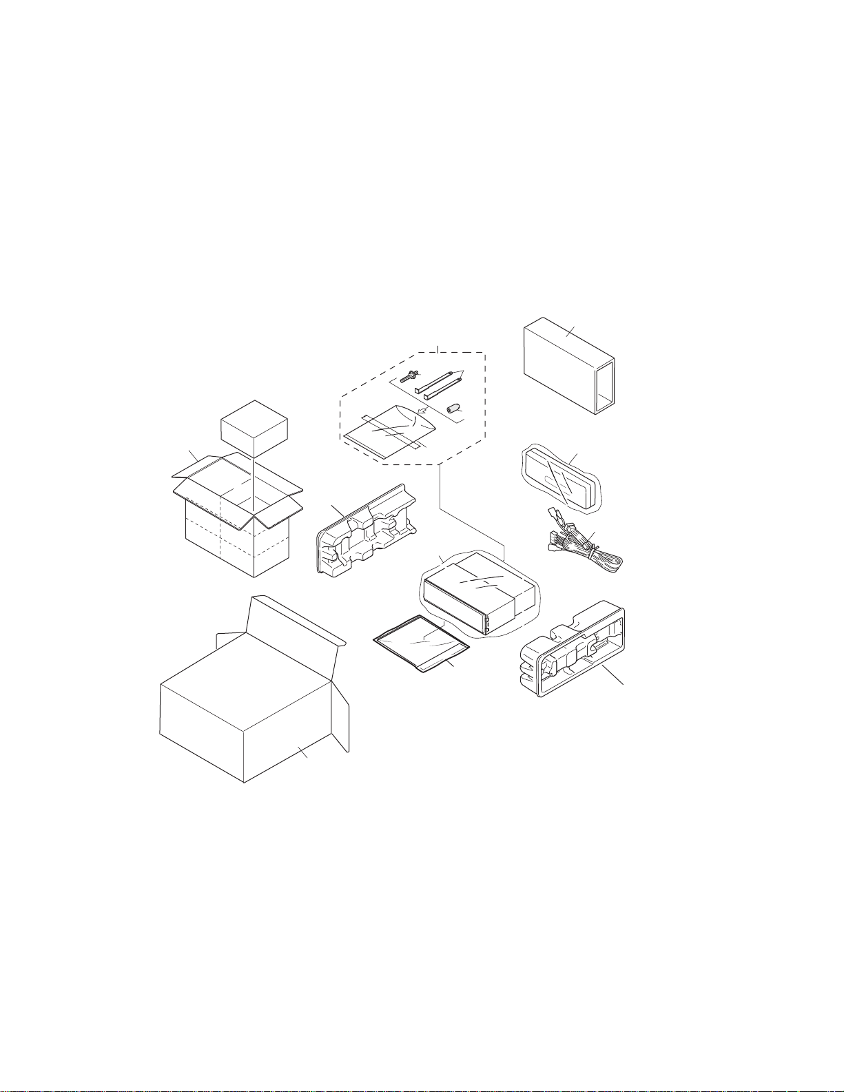
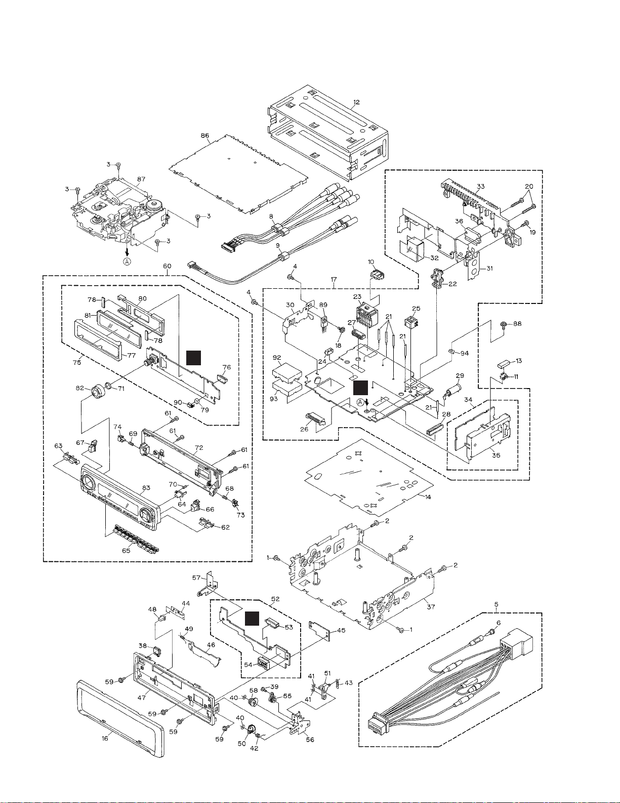
2. EXPLODED VIEWS AND PARTS LIST
2.1 PACKING(KEH-P8010R/X1N/EW)
9
14
8
13
12
6
5
7
4
3
1
15
2
11
1. SAFETY INFORMATION
This service manual is intended for qualified service technicians; it is not meant for the casual do-it-yourselfer.
Qualified technicians have the necessary test equipment and tools, and have been trained to properly and safely repair
complex products such as those covered by this manual.
Improperly performed repairs can adversely affect the safety and reliability of the product and may void the warranty.
If you are not qualified to perform the repair of this product properly and safely, you should not risk trying to do so
and refer the repair to a qualified service technician.
Page 3
3
KEH-P8010R,P8015
1 Carton CHG4331
2 Cord Assy CDE6435
* 3 Accessory Assy CEA2397
4 Screw CBA1002
5 Handle CNC5395
6 Bush CNV3930
* 7 Polyethylene Bag E36-615
8 Polyethylene Bag CEG1227
9-1 Polyethylene Bag CEG1116
9-2 Owner’s Manual CRD3364
9-3 Owner’s Manual CRD3365
9-4 Owner’s Manual CRD3366
9-5 Installation Manual CRD3367
* 9-6 Passport CRY1013
* 9-7 Warranty Card CRY1157
* 9-8 Caution Card CRP1207
* 9-9 Caution Card CRP1220
10 •••••
11 Contain Box CHL4331
12 Protector CHP2252
13 Protector CHP2251
14 Case Assy CXB3520
15 Inner Box CHW1754
Mark No. Description Part No. Mark No. Description Part No.
- PACKING SECTION PARTS LIST
NOTE:
- Parts marked by “*” are generally unavailable because they are not in our Master Spare Parts List.
- Screws adjacent to ∇ mark on the product are used for disassembly.
- Owner's Manual, Installation Manual
Model Part No. Language
KEH-P8010R/X1N/EW CRD3364 English, Spanish
CRD3365 German, French
CRD3366 Italian, Dutch
CRD3367 English, Spanish, German, French, Italian, Dutch
Page 4
4
KEH-P8010R,P8015
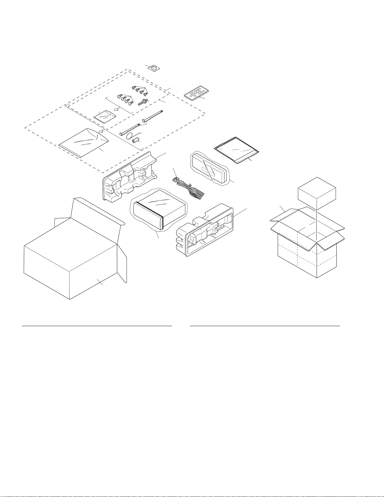
1 Carton CHG4332
2 Cord Assy CDE6438
* 3 Accessory Assy CEA2395
4 Spring CBH1650
* 5 Screw Assy CEA2396
6 Screw CBA1002
* 7 Polyethylene Bag CEG-127
8 Screw CRZ50P090FMC
9 Screw TRZ50P080FMC
* 10 Polyethylene Bag CEG-158
11 Handle CNC5395
12 Bush CNV3930
13 Polyethylene Bag CEG1227
* 14 Battery CEX1065
15 Contain Box CHL4332
16 Protector CHP2252
17 Protector CHP2251
18 Case Assy CXB3520
19-1 Polyethylene Bag CEG1116
19-2 Owner’s Manual CRD3368
19-3 Owner’s Manual CRD3369
19-4 Installation Manual CRD3370
* 19-5 Caution Card CRP1207
20 Remote Control Unit CXB6796
Mark No. Description Part No. Mark No. Description Part No.
- PACKING SECTION PARTS LIST
2.2 PACKING(KEH-P8015/X1N/ES)
20
14
5
8
12
4
11
10
9
7
6
17
2
18
13
16
15
1
19
3
Page 5

5
KEH-P8010R,P8015
- Owner's Manual, Installation Manual
Model Part No. Language
KEH-P8015/X1N/ES CRD3368 English, Spanish, Portuguese(B)
CRD3369 Arabic, Chinese
CRD3370 English, Spanish, Portuguese(B), Arabic, Chinese
Page 6
6
KEH-P8010R,P8015
2.3 EXTERIOR(KEH-P8010R/X1N/EW)
A
B
C
Page 7

7
KEH-P8010R,P8015
1 Screw BMZ30P040FZK
2 Screw BMZ30P100FMC
3 Screw BSZ26P060FMC
4 Screw BSZ30P040FMC
5 Cord Assy CDE6435
6 Terminal Cover CKX-003
7 •••••
8 Cord Assy CDE6453
9 Cord Assy CDE6455
10 Fuse(10A) CEK1136
11 Holder CNC5704
12 Holder CNC8659
13 Cushion CNM4870
14 Insulator CNM6948
15 •••••
16 Panel CNS6552
17 Tuner Amp Unit CWM7460
18 Screw ASZ26P060FMC
19 Screw BPZ26P120FMC
20 Screw BSZ26P160FMC
21 Clamper CEF1007
22 Pin Jack(CN351) CKB1035
23 Plug(CN901) CKM1330
* 24 Plug(CN451) CKS1052
25 Connector(CN101) CKS3408
26 Plug(CN801) CKS3537
27 Connector(CN352) CKS3602
28 Connector(CN251) CKS3568
29 Antenna Jack(CN401) CKX1056
30 Holder CNC8615
31 Holder CNC9468
32 Insulator CNM6949
33 Heat Sink CNR1583
34 FM/AM Tuner Unit CWE1562
35 Holder CNC8815
36 IC(IC301) PAL006A
37 Chassis Unit CXB6461
38 Button(EJECT) CAC6839
39 Screw(M2x2) CBA1176
40 Washer CBF1038
41 Washer CBF1039
42 Spring CBH2428
43 Spring CBH2429
44 Spring CBL1512
45 Holder CNC9096
46 Door CAT2109
47 Panel CNS6280
48 Pin CNV6486
49 Spring CBH1838
50 Gear CNV6507
51 Arm CNV6508
52 Panel Unit CWM7627
53 Socket(CN1950) CKS3550
54 Connector(CN1951) CKS4206
55 Damper Unit CXB5070
56 Holder Unit CXB6356
57 Holder Unit CXB6357
58 Clutch Unit CXB6358
59 Screw IMS20P045FZK
60 Detach Grille Assy CXB6549
61 Screw BPZ20P100FZK
62 Button(FUNC AUDIO) CAC6776
63 Button(SOURCE DISP) CAC6777
64 Button(OPEN) CAC6780
65 Button(1-6) CAC6841
66 Button(SFEQ) CAC6842
67 Button(EQ) CAC6840
68 Spring CBH2430
69 Spring CBH2431
70 Spring CBH2491
71 Spring CBL1470
72 Cover CNS6282
73 Holder CNV6505
74 Holder CNV6506
75 Keyboard Unit CWM7466
76 Connector(CN1901) CKS4524
77 Holder CNC9112
78 Cushion CNM6633
* 79 Spacer CNM7469
80 Holder CNV6105
81 OEL Unit MXS8016
82 Knob Unit CXB7239
83 Sub Grille Assy CXB7254
84 •••••
85 •••••
86 Case Unit CXB7481
87
Cassette Mechanism Module EXK4060
88 Screw ISS26P055FUC
89 Transistor(Q921) 2SD2396
90 IC(IC1903) TSOP1840SB1
91 •••••
92 Case CNC8138
93 Insulator CNM6249
94 Holder CNC5399
- EXTERIOR SECTION PARTS LIST
Mark No. Description Part No.
Mark No. Description Part No.
Page 8
8
KEH-P8010R,P8015
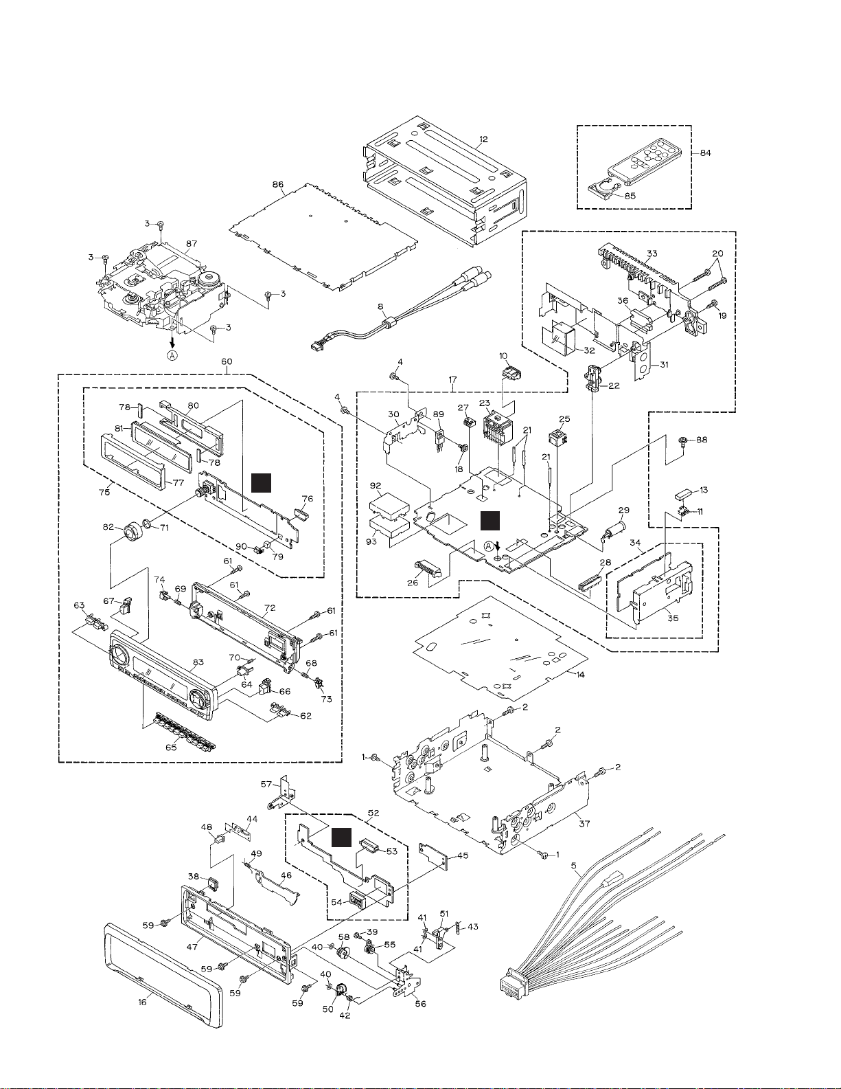
2.4 EXTERIOR(KEH-P8015/X1N/ES)
A
B
C
Page 9

9
KEH-P8010R,P8015
1 Screw BMZ30P040FZK
2 Screw BMZ30P100FMC
3 Screw BSZ26P060FMC
4 Screw BSZ30P040FMC
5 Cord Assy CDE6438
6 •••••
7 •••••
8 Cord Assy CDE6454
9 •••••
10 Fuse(10A) CEK1136
11 Holder CNC5704
12 Holder CNC8659
13 Cushion CNM4870
14 Insulator CNM6948
15 •••••
16 Panel CNS6553
17 Tuner Amp Unit CWM7462
18 Screw ASZ26P060FMC
19 Screw BPZ26P120FMC
20 Screw BSZ26P160FMC
21 Clamper CEF1007
22 Pin Jack(CN351) CKB1035
23 Plug(CN901) CKM1330
24 •••••
25 Connector(CN101) CKS3408
26 Plug(CN801) CKS3537
27 Connector(CN352) CKS3598
28 Connector(CN251) CKS3568
29 Antenna Jack(CN401) CKX1056
30 Holder CNC8615
31 Holder CNC9470
32 Insulator CNM6949
33 Heat Sink CNR1583
34 FM/AM Tuner Unit CWE1563
35 Holder CNC8815
36 IC(IC301) PAL006A
37 Chassis Unit CXB6106
38 Button(EJECT) CAC6839
39 Screw(M2x2) CBA1176
40 Washer CBF1038
41 Washer CBF1039
42 Spring CBH2428
43 Spring CBH2429
44 Spring CBL1512
45 Holder CNC9096
46 Door CAT2109
47 Panel CNS6280
48 Pin CNV6486
49 Spring CBH1838
50 Gear CNV6507
51 Arm CNV6508
52 Panel Unit CWM7627
53 Socket(CN1950) CKS3550
54 Connector(CN1951) CKS4206
55 Damper Unit CXB5070
56 Holder Unit CXB6356
57 Holder Unit CXB6357
58 Clutch Unit CXB6358
59 Screw IMS20P045FZK
60 Detach Grille Assy CXB6551
61 Screw BPZ20P100FZK
62 Button(FUNC AUDIO) CAC6776
63 Button(SOURCE DISP) CAC6777
64 Button(OPEN) CAC6780
65 Button(1-6) CAC6841
66 Button(SFEQ) CAC6842
67 Button(EQ) CAC6840
68 Spring CBH2430
69 Spring CBH2431
70 Spring CBH2491
71 Spring CBL1470
72 Cover CNS6282
73 Holder CNV6505
74 Holder CNV6506
75 Keyboard Unit CWM7467
76 Connector(CN1901) CKS4524
77 Holder CNC9112
78 Cushion CNM6633
* 79 Spacer CNM7469
80 Holder CNV6105
81 OEL Unit MXS8016
82 Knob Unit CXB7239
83 Sub Grille Assy CXB7255
84 Remote Control Unit CXB6796
85 Cover CNS6439
86 Case Unit CXB7481
87
Cassette Mechanism Module
EXK4060
88 Screw ISS26P055FUC
89 Transistor(Q921) 2SD2396
90 IC(IC1903) TSOP1840SB1
91 •••••
92 Case CNC8138
93 Insulator CNM6249
- EXTERIOR SECTION PARTS LIST
Mark No. Description Part No.
Mark No. Description Part No.
Page 10
10
KEH-P8010R,P8015
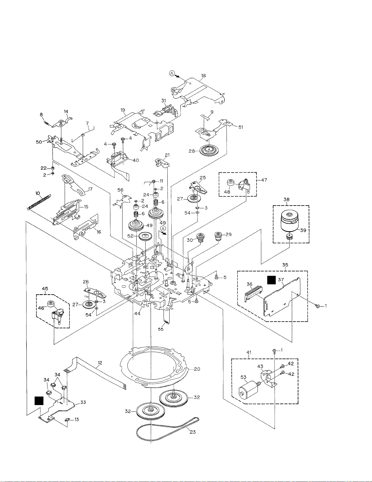
2.5 CASSETTE MECHANISM MODULE
D
E
Page 11

11
KEH-P8010R,P8015
1 Screw BSZ20P040FMC
2 Washer CBF1037
3 Washer CBG1003
4 Screw EBA1028
5 Screw CBA1037
6 Spring EBH1531
7 Spring EBH1642
8 Spring EBH1641
9 Spring EBH1626
10 Spring EBH1627
11 Spring EBH1648
12 Cord EDD1024
13 Photo-reflector(EGN1) EGN1004
14 Arm ENC1526
* 15 Lever ENC1544
16 Lever ENC1543
17 Arm ENC1532
18 Frame ENC1533
19 Holder ENC1534
20 Gear ENC1535
21 Arm ENC1550
22 Roller ENR1040
23 Belt ENT1027
24 Collar ENV1508
25 Arm ENV1539
26 Arm ENV1540
27 Gear ENV1544
28 Gear ENV1547
29 Gear ENV1560
30 Worm Wheel ENV1566
31 Lever ENV1551
32 Flywheel ENV1554
33 Gathering PCB ENX1068
34 Switch(S1,S2,S3) ESG1007
35 Deck Unit EWM1033
36 Plug(CN251) CKS3540
37 Gathering PCB ENX1067
38 Motor Unit(M1) EXA1490
39 Motor EXM1027
40 Head Assy(HD1) EXA1589
41 Motor Unit(M2) EXA1580
42 Screw BMZ20P022FMC
43 Bracket ENC1528
44 Chassis Unit EXA1615
45 Pinch Holder Unit EXA1608
46 Pinch Roller ENV1518
47 Pinch Holder Unit EXA1607
48 Pinch Roller ENV1518
49 Reel Unit EXA1585
50 Head Base Unit EXA1611
51 Lever Unit EXA1587
52 Gear Unit EXA1596
53 Motor Unit(Service) EXX1055
54 Washer HBF-179
55 Spring EBH1537
56 Arm ENC1537
Mark No. Description Part No. Mark No. Description Part No.
- CASSETTE MECHANISM MODULE SECTION PARTS LIST
Page 12
12
KEH-P8010R,P8015
1
23
4
1
234
D
C
B
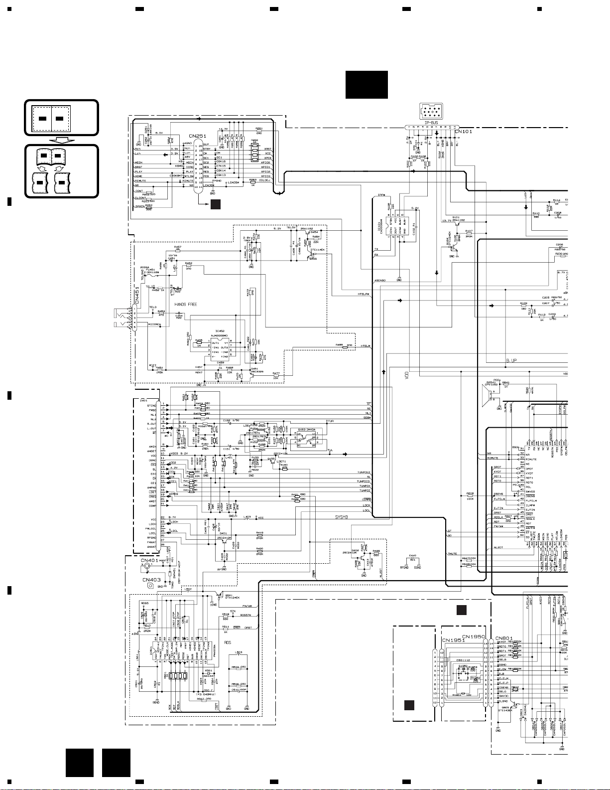
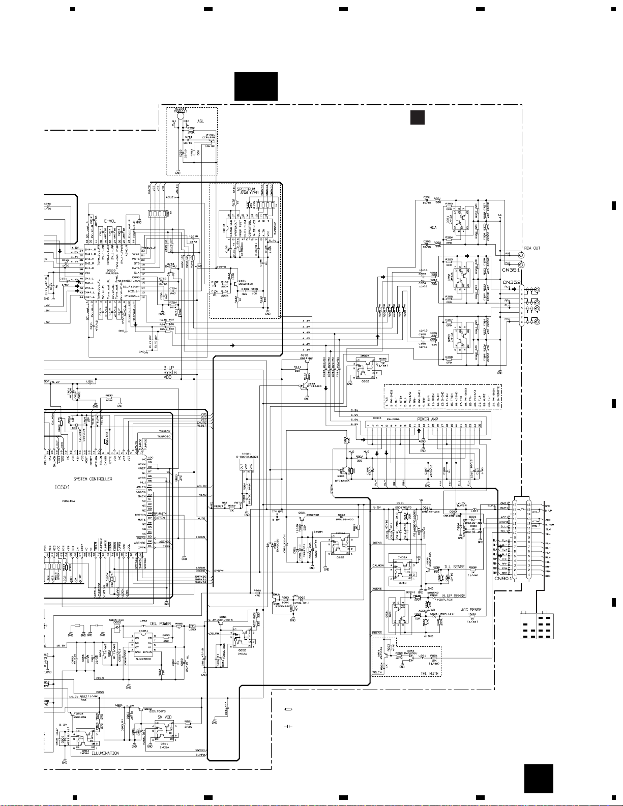
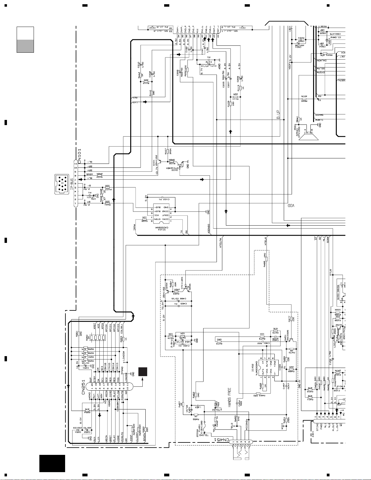
A
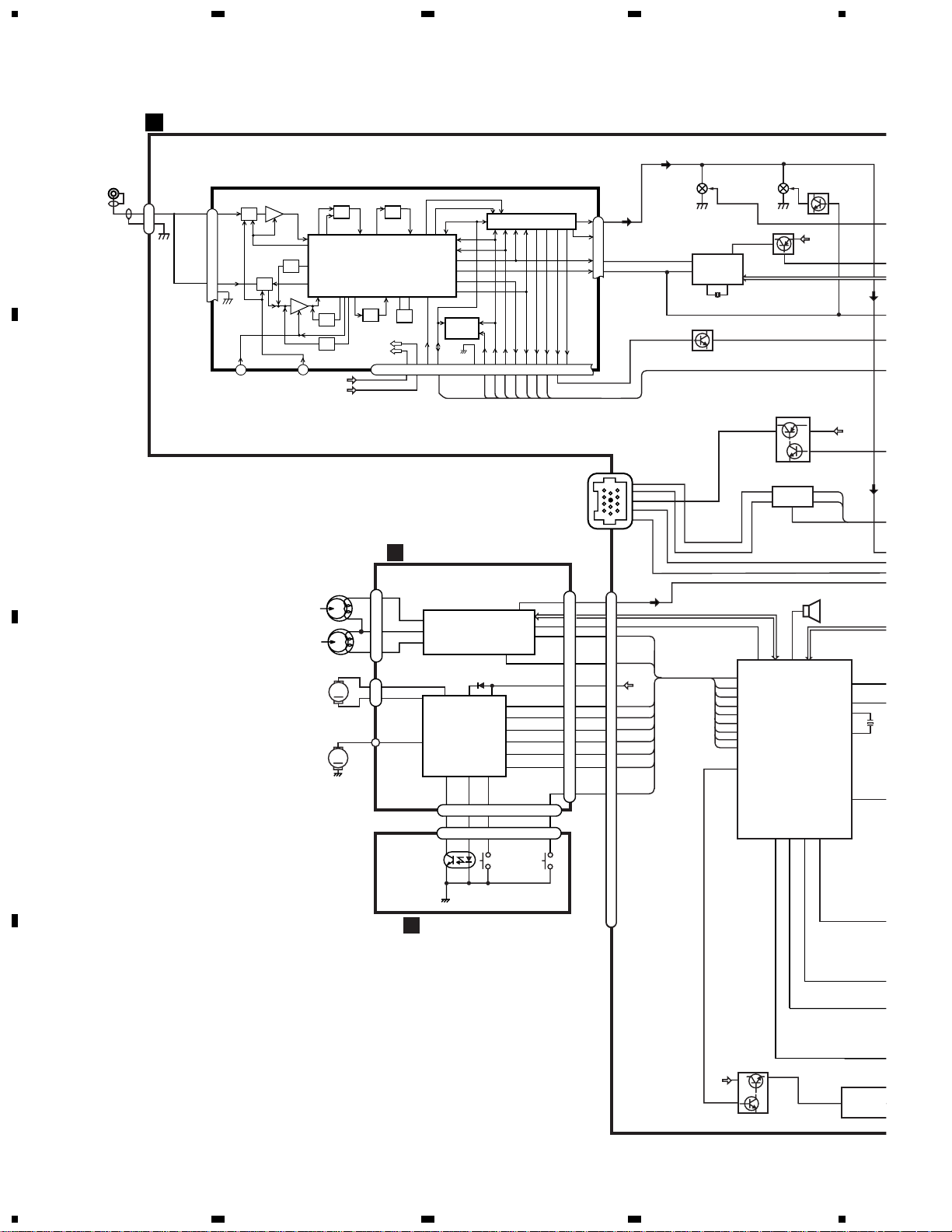
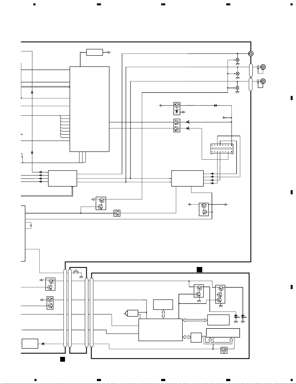
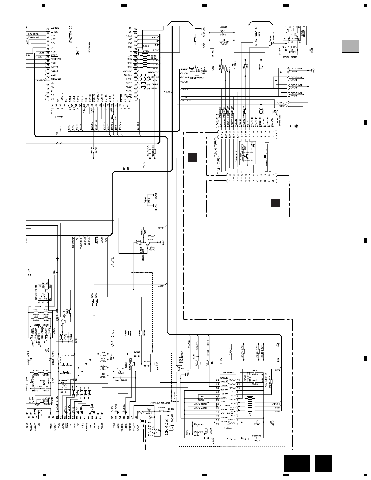
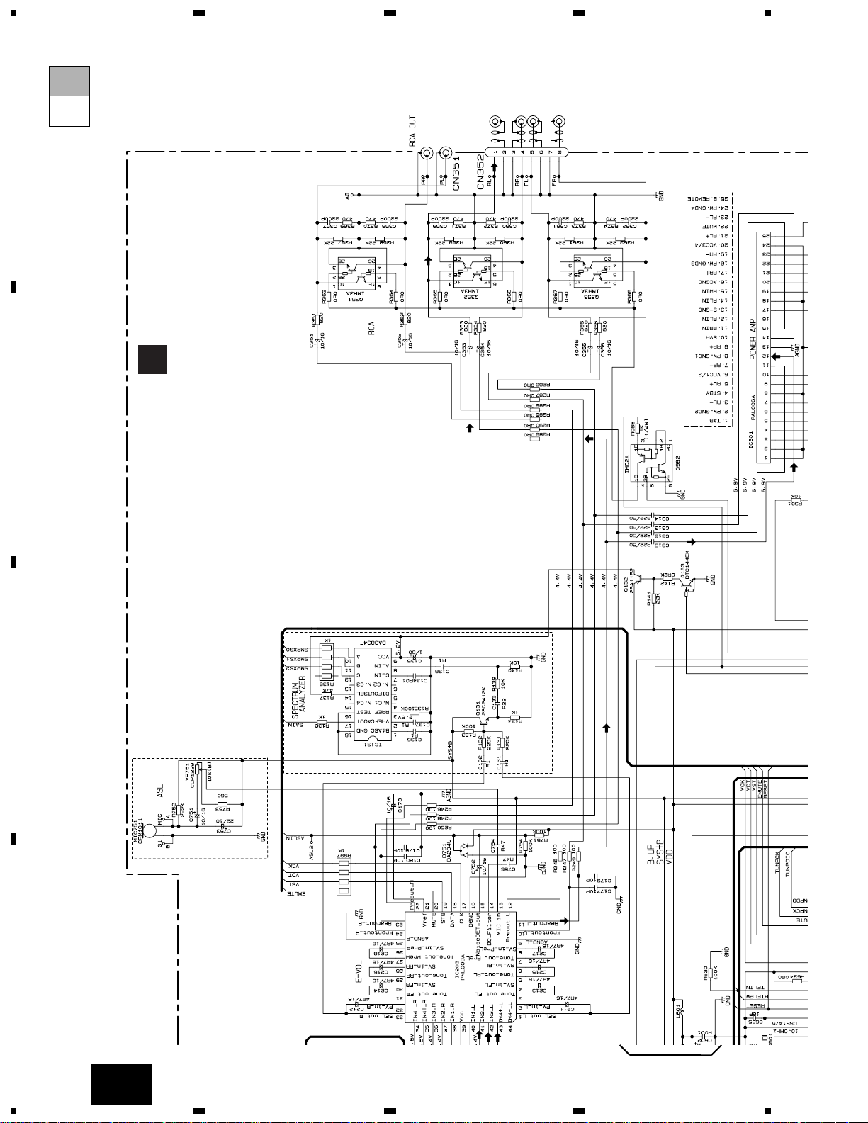
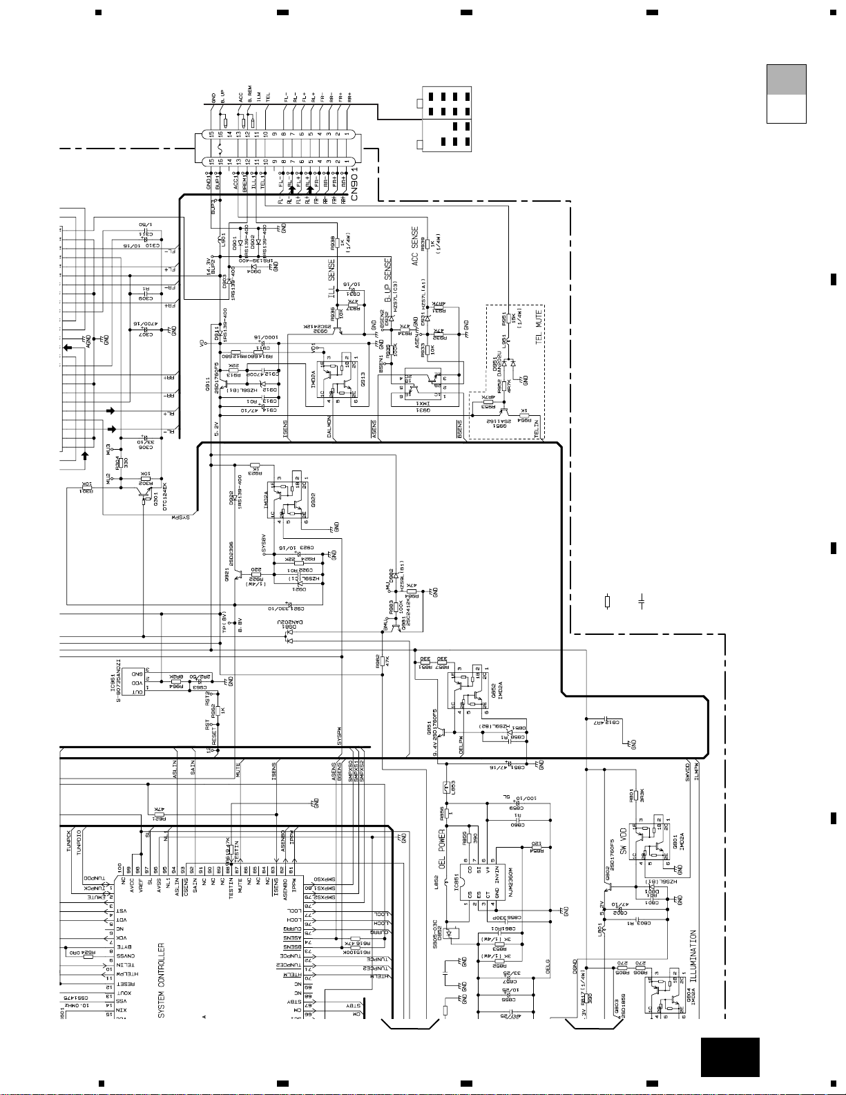
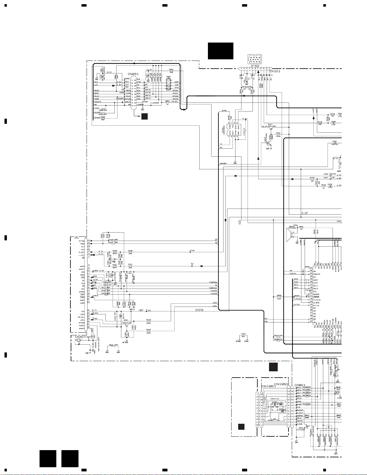
3. BLOCK DIAGRAM AND SCHEMATIC DIAGRAM
3.1 BLOCK DIAGRAM
Q153 Q151
Q402
Q155
Q501
IC 501
PM4009A(EW)
IC 101
CA0008AM
X501
RDS
DECODER
IP-BUS DRIVER
1211
20
8
87
MUTE
XOUT
XIN
PEE
24
OELPW
22
40
SYSTEM µ-COM
IC 601(2/2)
PD5616A(EW)
PD5617A(ES)
CN401
VDD
VCC
ANT
1
2
BUS—
BU
BUS+
BUS+L
BUS—L
1
2
8
6
5
TX
RX
IPPW
SWVDD
CN251
BU
Q852
A
TUNER AMP UNIT
13
X60
15
14
1
24
VDD
SWDACC
TUN
BUS+L
BUS—L
TAPE L
Q851
35
DPDT
36
KYDT
23
SYSPW
Q101
Q102
IC 851
NJM2360M
6
EJTIN
44
DIRO
LOADSW
POS
NES
SC2
55
58
59
61
63
BU
54
MSIN
65
SC1
RIMUTE
33
66
67
CM
STBY
RIMUTE
DIRO
POS
NES
SC2
SC1
CM
STBY
LOADSW
43
ILMPW
5
8
1
7
CN101
11
BUZZER
IC 3
EEPROM
FM/AM TUNER UNIT
28
27
FM/AM 1ST IF 10.7MHz
T51 Q51 CF51
CF52 CF53
IC1
MIXER, IF AMP, DET.
6
21
18
LDET
COMP
222510 14 12 15 16 8 13 2 3 4
CF202
VDD
VCC
DI/DO
CE2CKCE1
SDBWSLFMSD
NL1
NL2
IC 2 FM MPX
AMANT
FMANT
ATT
ATT
AMRF
FMRF
RF ADJ
ANT2 ADJ
X901
10.25MHz
ANT1 ADJ
LOCL
23
LOCH
AMDET
MPXREF 41kHz
AM 2ND IF
450kHz
19
CREQ
11
DGND
1
STIND
L ch
5
R ch
924
NC
FMLOCL
20177
NCNCWC
26
RFGND
stby
B.U
MUTE
LOAD
5
1
4
2
1
3
11
9
20
19
D
DECK UNIT
IC251
HA12228F
IC351
PA2020A
EQ AMP
MECHANISM
DRIVER
CN251
CN252
CN254
CN255
CN253
6
16
MS
Lch
20
FWD
L-ch
REV
L-ch
37
36
39
18
19
17
3
15 6
8
7
10
CN256
3
15 6
S1
LOAD
S2
MODE
EGN1
REEL
SENSE
M
M
M2
SUB
MOTOR
M1
MAIN
MOTOR
5
2
1
E
REEL SENSE PCB
6
5
17
f/R
15
13
13
11
POS
NES
18
17
16
15
SC1
CM
16
14
SC2
3
11
9
20
19
6
5
15
13
18
17
16
Page 13
13
KEH-P8010R,P8015
5
6
78
5
6
7
8
D
C
B
A
C
19
ldet
48
fm/AM
52
12
1
TMUTE
bsens
asens
NL2DT
VDD
BU
NL1
74
73
SD
SL
SDBW
TUNPCE
TUNPCK
tunpce@
TUNPDO
ASENBO
10
FL
11
RL
87
XIN
ILB
SWVDD
OELB
ILB
SWDVDD
OELB
23
21
3
5
FL—
FL+
RL—
RL+
ACC
51
95
50
97
IN3-L
42
IN4+L
43
IN4-L
44
IN2-L
41
53
72
2
71
1
82
30 29 81
FLIN
14
RLIN
12
22 4
SYSTEM µ-COM
RESET
POWER AMP
IC 601(1/2)
IC 203
PML009A
IC 961
S-80735ANDZI
IC 301
PAL006A
RESET
VDD
Q911
Q931
SYSPW
BU
TXRXIPPW
ELECTRONIC VOLUME/
SOURCE SELECTOR
BU
BU
STBYMUTE
IC 1901
PD5627A
GRILLE µ-COM
KEY MATRIX
9
11
8
KEY DATA
OEL DATA
VCC
70
CN801
CN1901
Q803
Q804
Q802
KEYBOARD UNIT
13
X601
15
2
ACC
VST,VCK,VDT
TUN L
BUS+L
BUS—L
TAPE L
DPDT
3
5
DPDT
KYDT
SYS+B
BU
Q921
Q922
23
PW
BU
ACC
RL+
FL+
RL-
FL-
Q301
MUTE
RL
Q351
RL
1
Q352
FL
5
Q353
FL
PRE OUT L
12
PL
Q801
IC 851
NJM2360M
44
7
2
10
11
14
8
7
2
10
11
14
8
CN1950
CN1951
S1950
KYDT
4
2
5
10
8
IC 1902
PD8074A
ROM
IC 1903
TSOP1840SB1
REMOTE
CONTROL
SENSOR
OPT IN
3
1
5
Q1901
Q1903
Q1902
Q1904
Q1905
ILMD
32
AMBER
GREEN
REM
34
33
DPDT
KTDT
EJECT
IC 1904
PD5536A
OEL
CONTROLLER
Q1908
4,16
8
B
PANEL UNIT
PD5616A(EW)
PD5617A(ES)
OEL MODULE
CN901
Q982
B.U
CN351
CN352-1
CN352-2
1
2
10
16
15
MUTE
Page 14
14
KEH-P8010R,P8015
1
23
4
1
234
D
C
B
A
3.2 OVERALL CONNECTION DIAGRAM(GUIDE PAGE)(KEH-P8010R/X1N/EW)
Note: When ordering service parts, be sure to refer to “EXPLODED VIEWS AND PARTS LIST” or “ELECTRICAL PARTS
LIST”.
A-a
A-b
A-b
A-a
A
>
C
EJECT SW
IP-BUS
DRIVER
TAPE(0dB):-11.2dBs
IP-BUS:+2.2dBs
FM(100%):-15.5dBs
AM(30%):-26.0dBs
FM
A
C
KEYBOARD UNIT
CN1901
PANEL UNIT
D
CN251
FM/AM TUNER UNIT
B
TEL/MIC
A-a
B
A-a A-b
A-a
A-b
Large size
SCH diagram
Guide page
A-a
A-b
Detailed page
Page 15
15
KEH-P8010R,P8015
5
6
78
5
6
7
8
D
C
B
A
A
600µH
DETACH
SENSE SW
CEK1136
10A
FUSE
>
RESET
R860
C854
0R0
1
AM(30%): -27.0dBs
IP-BUS: +2.2dBs
TAPE:-11.24dBs
FM(100%): +6.6dBs
AM(30%): -1.9dBs
IP-BUS: +9.3dBs
TAPE:-4.14dBs
FM(100%): +32.6dBs
AM(30%): +24.1dBs
IP-BUS: +35.3dBs
TAPE:+21.86dBs
FM(100%):+5.84dBs
AM(30%): -2.66dBs
IP-BUS:+8.54dBs
TAPE: -4.9dBs
A
TUNER AMP UNIT
Decimal points for resistor
and capacitor fixed values
are expressed as :
2.2 2R2
0.022 R022
←
←
The > mark found on some component parts indicates
the importance of the safety factor of the part.
Therefore, when replacing, be sure to use parts of
identical designation.
Symbol indicates a resistor.
No differentiation is made between chip resistors and
discrete resistors.
NOTE :
Symbol indicates a capacitor.
No differentiation is made between chip capacitors and
discrete capacitors.
RR–
FR–
FL–
RL–
RR+
FR+
FL+
RL+
BACK UP
ILL
GND
B.REM
ACC
A-b
Page 16
16
KEH-P8010R,P8015
1
23
4
1
234
D
C
B
A
A-a
A-a
A-b
1
>
IP-BUS
DRIVER
TAPE(0dB):-11.2dBs
IP-BUS:+2.2dBs
0%):-15.5dBs
0%):-26.0dBs
FM(100%): -16.5dBs
AM(30%): -27.0dBs
IP-BUS: +2.2dBs
TAPE:-11.24dBs
D
CN251
TEL/MIC
Page 17
17
KEH-P8010R,P8015
5
6
78
5
6
7
8
D
C
B
A
A-a
A-a
A-b
DETACH
SENSE SW
EJECT SW
R860
C
0R0
FM(100%):-15.5dBs
AM(30%):-26.0dBs
C
KEYBOARD UNIT
CN1901
PANEL UNIT
FM/AM TUNER UNIT
B
2
3
B
Page 18
18
KEH-P8010R,P8015
1
23
4
1
234
D
C
B
A
A-a
A-b
A-b
FM(100%): +6.6dBs
AM(30%): -1.9dBs
IP-BUS: +9.3dBs
TAPE:-4.14dBs
FM(100%):+5.84dBs
AM(30%): -2.66dBs
IP-BUS:+8.54dBs
TAPE: -4.9dBs
A
TUNER AMP UNIT
1
Page 19
19
KEH-P8010R,P8015
5
6
78
5
6
7
8
D
C
B
A
A-b
A-a
A-b
600µH
CEK1136
10A
FUSE
>
RESET
R860
C854
0R0
1
FM(100%): +32.6dBs
AM(30%): +24.1dBs
IP-BUS: +35.3dBs
TAPE:+21.86dBs
Decimal points for resistor
and capacitor fixed values
are expressed as :
2.2 2R2
0.022 R022
←
←
The > mark found on some component parts indicates
the importance of the safety factor of the part.
Therefore, when replacing, be sure to use parts of
identical designation.
Symbol indicates a resistor.
No differentiation is made between chip resistors and
discrete resistors.
NOTE :
Symbol indicates a capacitor.
No differentiation is made between chip capacitors and
discrete capacitors.
RR–
FR–
FL–
RL–
RR+
FR+
FL+
RL+
BACK UP
ILL
GND
B.REM
ACC
2
3
Page 20
20
KEH-P8010R,P8015
1
23
4
1
234
D
C
B
A
3.3 OVERALL CONNECTION DIAGRAM(GUIDE PAGE)(KEH-P8015/X1N/ES)
Note: When ordering service parts, be sure to refer to “EXPLODED VIEWS AND PARTS LIST” or “ELECTRICAL PARTS
LIST”.
EJECT SW
DETACH SENSE SW
IP-BUS
DRIVER
TAPE(0dB):-11.2dBs
IP-BUS:+2.2dBs
FM(100%):-19.5dBs
AM(30%):-30.0dBs
FM(1
AM
IP
C
KEYBOARD UNIT
CN1901
B
PANEL UNIT
D
CN251
FM/AM TUNER UNIT
A-a
A B
Page 21
21
KEH-P8010R,P8015
5
6
78
5
6
7
8
D
C
B
A
A
600µH
DETACH SENSE SW
CEK1136
10A
FUSE
>
RESET
IP-BUS: +2.2dBs
TAPE:-11.24dBs
FM(100%): +2.6dBs
AM(30%): -7.9dBs
IP-BUS: +7.3dBs
TAPE:-6.14dBs
FM(100%): +28.6dBs
AM(30%): +18.1dBs
IP-BUS: +33.3dBs
TAPE:+19.86dBs
A
TUNER AMP UNIT
A-b
Page 22

22
KEH-P8010R,P8015
1
23
4
1
234
D
C
B
A
A-a
A-a
A-b
IP-BUS
DRIVER
TAPE(0dB):-11.2dBs
IP-BUS:+2.2dBs
(100%):-19.5dBs
M(30%):-30.0dBs
FM(100%): -20.5dBs
AM(30%): -31.0dBs
IP-BUS: +2.2dBs
TAPE:-11.24dBs
D
CN251
1
Page 23

23
KEH-P8010R,P8015
5
6
78
5
6
7
8
D
C
B
A
A-a
A-b
EJECT SW
DETACH SENSE SW
FM(100%):-19.5
AM(30%):-30.0
C
KEYBOARD UNIT
CN1901
B
PANEL UNIT
FM/AM TUNER UNIT
2
3
A-a
B
Page 24

24
KEH-P8010R,P8015
1
23
4
1
234
D
C
B
A
A-a
A-b
A-b
RESET
FM(100%): +2.6dBs
AM(30%): -7.9dBs
IP-BUS: +7.3dBs
TAPE:-6.14dBs
A
TUNER AMP UNIT
1
Page 25

25
KEH-P8010R,P8015
5
6
78
5
6
7
8
D
C
B
A
A-b
A-a
A-b
600µH
CEK1136
10A
FUSE
>
RESET
FM(100%): +28.6dBs
AM(30%): +18.1dBs
IP-BUS: +33.3dBs
TAPE:+19.86dBs
2
3
Page 26

26
KEH-P8010R,P8015
1
23
4
1
234
D
C
B
A
3.4 KEYBOARD UNIT(KEH-P8010R/X1N/EW)
SFEQ
CSG1147
R1940
0R0
R1949
1R0
CSG1113
CSG1147
CSG1115
B
CN1951
REMOTE CONTROL
SENSOR
S1930
CSD1059
VOLUME
1
3
2
5
4
1
GND
2
NC2
NC1
C
Page 27

27
KEH-P8010R,P8015
5
6
78
5
6
7
8
D
C
B
A
C
KEYBOARD UNIT
OEL UNIT
MXS8016
GRILLE µ-COM
ROM
OEL CONTROLLER
C
Page 28

28
KEH-P8010R,P8015
1
23
4
1
234
D
C
B
A
3.5 KEYBOARD UNIT(KEH-P8015/X1N/ES)
ATT
SFEQ
CSG1146
R1940
0R0
R1949
1R0
B
CN1951
REMOTE CONTROL
SENSOR
S1930
CSD1059
VOLUME
1
3
2
5
4
1
GND
2
NC2
NC1
C
Page 29

29
KEH-P8010R,P8015
5
6
78
5
6
7
8
D
C
B
A
C
KEYBOARD UNIT
OEL UNIT
MXS8016
GRILLE µ-COM
ROM
OEL CONTROLLER
C
Page 30

30
KEH-P8010R,P8015
1
23
4
1
234
D
C
B
A
DECK UNIT
MUTE
HA12228F
11
12
13
14
15
16
17
18
19
20
40
39
38
37
36
35
34
33
32
31
30
292827
26
252423
22
21
1
234
5
678
9
10
C253
390P
C251
C256
R01
C405
R033
R404
270K
R01
C404
910
R403
3R3K
C255
R01
C272
R1
C401
3900P
R285 0R0
HD1
HEAD ASSY
EXA1589
TEST TAPE
NCT-150
(400Hz, 200nWb/m)
RL
RR
FR
FL
C302
R1
C301
R1
VR301
33K(B)
-8.24dBs±1dB
Fwd-R
Fwd-L
Rev-R
Rev-L
NF1(R)
Vref1
RIN(L)
NC
RIN(R)
GND
FIN(R)
Vref2
FIN(L)
NFI(L)
M-OUT(L)
EQOUT(L)
Vref4
TAI(L)
BIAS
NC
NC
MSGV(S)
MUTE
120/70
ser/REP
f/R
MSDET
MSI
MAOUT
MSGV(R)
MOUT(R)
EQOUT(R)
Vref3
TAI(R)
RIP
PBOUT(R)
NC
DET(R)
NRONoff
CN252
CN251
Dolby-B
IC251
390P
C252
390P
C254
390P
PBOUT(L)
NC
VCC
MSOUT
NC
C403
R022
R402
R33
C402
15K
R401
18K
R271
C271
1/50
C310
R1
C309
R1
CCP1280
VR302
33K(B)
CCP1280
3.6 CASSETTE MECHANISM MODULE
D
D
CN251
A
Page 31

31
KEH-P8010R,P8015
5
6
78
5
6
7
8
D
C
B
A
REEL SENSE
PCB
SWITCHES:
REEL SENSE PCB
S1:LOAD SWITCH..........EJECT-PLAY
S2:MODE SWITCH............ON-OFF
S3:70µs SWITCH............ON-OFF
The underlined indicates the switch position.
33
R351 1K
R352 1K
R353 1K
R354 1K
R373 0R0
R355 270K
C352
3900P
R362 300
C351 R22
C353 R01
C354 R01
R374 0R0
C356 R01
C355 R1
D352 1SS355
M1 MOTOR UNIT
(MAIN MOTOR)
EXA1490
S1
LOAD
ESG1007
S2
ESG1007
MODE
REEL SENSE
EGN1
EGN1004
M2
MOTOR UNIT
(SUB MOTOR)
EXA1580
RS3
RS2
RS1
SC2
SC1
TAB
MC
CE
VCC2
NC
VCC
MCS
RRS
FRS
RSB
C
TAB
MS2
NC
NC
MM
SM1
RSB
GND
RS
mtl
MCS
load
CN255
CN253
CN256
CN254
MECHANISM
DRIVER
IC351 PA2020A
R022
S3
ESG1007
70µs
R375
0R0
D
E
E
Page 32

32
KEH-P8010R,P8015
1
23
4
1
234
D
C
B
A
NOTE FOR PCB DIAGRAMS
1. The parts mounted on this PCB
include all necessary parts for
several destination.
For further information for
respective destinations, be
sure to check with the
schematic diagram.
2. Viewpoint of PCB diagrams
A
4. PCB CONNECTION DIAGRAM
4.1 TUNER AMP UNIT
TUNER AMP UNIT
CORD ASSY
FRONT OUTPUT,
REAR OUTPUT
MIC, TEL
DETACH SENSE
A
16 2
115
Connector
Capacitor
SIDE A
P.C.Board
Chip Part
SIDE B
5
1
Page 33

33
KEH-P8010R,P8015
5
6
78
5
6
7
8
D
C
B
A
A
IC, Q
FRONT
14
57
811
1
21
20
2
SIDE A
IP-BUS
SWBWOOFER OUTPUT
ANTENNA
FM/AM TUNER UNIT
CN1950
B
CN251
D
Page 34

34
KEH-P8010R,P8015
1
23
4
1
234
D
C
B
A
A
IC, Q
TUNER AMP UNIT
A
Page 35

35
KEH-P8010R,P8015
5
6
78
5
6
7
8
D
C
B
A
A
SIDE B
Page 36

36
KEH-P8010R,P8015
1
23
4
1
234
D
C
B
A
EJECT
1357911
24681012
4.2 PANEL UNIT
SIDE A
PANEL UNIT
B
B
PANEL UNIT
B
SIDE B
CN1901
C
CN801
A
Page 37

37
KEH-P8010R,P8015
1
2
34
1
2
3
4
D
C
B
A
IC, Q
EQ
VOLUME
SOURCE DISPLAY 1 2 3 4 5 6 TA(EW)
ATT(ES)
BAND FUNCTION AUDIO
'
'
'
'
SFEQ
TEXT(EW)
CLOCK(ES)
ENTERTAINMENT
4.3 KEYBOARD UNIT
SIDE A
KEYBOARD UNIT
IC, Q ADJ
TP1
TP2
12108642
1197531
R1940
R1949
SIDE B
C
C
KEYBOARD UNIT
C
CN1951
B
Page 38

38
KEH-P8010R,P8015
1
23
4
1
234
D
C
B
A
CN251
C271
IC,Q
IC251
Q351
Q352
ADJ
VR302
VR301
IC351
CN252
CN254
CN253
CN255
M1
M2
HEAD ASSY
CN256
21
22
4.4 CASSETTE MECHANISM MODULE
CN251
A
DECK UNIT
DECK UNIT
D
D
D
E
SIDE A
SIDE B
Page 39

39
KEH-P8010R,P8015
1
2
34
1
2
3
4
D
C
B
A
1
2
3
4
5
6
S1
LOAD
S2
MODE
S3
70µs
CN256
EGN1
REEL SENSE
CN253
REEL SENSE PCB
E
D
E
Page 40

40
KEH-P8010R,P8015
5. ELECTRICAL PARTS LIST
NOTES:
- Parts whose parts numbers are omitted are subject to being not supplied.
- The part numbers shown below indicate chip components.
Chip Resistor
RS1/_S___J,RS1/__S___J
Chip Capacitor (except for CQS.....)
CKS....., CCS....., CSZS.....
=====Circuit Symbol and No.===Part Name Part No.
--- ------ ------------------------------------------ -------------------------
Unit Number : CWM7460(KEH-P8010R/X1N/EW)
Unit Name : Tuner Amp Unit
MISCELLANEOUS
IC 101 IC CA0008AM
IC 131 IC BA3834F
IC 203 IC PML009A
IC 301 IC PAL006A
IC 452 IC NJM2068MD
IC 501 IC PM4009A
IC 601 IC PD5616A
IC 851 IC NJM2360M
IC 961 IC S-80735ANDZI
Q 101 Transistor 2SA1162
Q 102 Transistor DTC124EK
Q 131 Transistor 2SC2412K
Q 132 Transistor 2SA1162
Q 133 Transistor DTC144EK
Q 151 Transistor 2SD1757K
Q 152 Transistor 2SD1757K
Q 153 Transistor IMH3A
Q 155 Transistor 2SC2412K
Q 301 Transistor DTC124EK
Q 351 Transistor IMH3A
Q 352 Transistor IMH3A
Q 353 Transistor IMH3A
Q 401 Transistor 2SC2412K
Q 402 Transistor 2SC2412K
Q 451 Transistor 2SC3326
Q 454 Transistor 2SA1162
Q 455 Transistor DTC114EK
Q 501 Transistor DTA124EK
Q 801 Transistor IMD2A
Q 802 Transistor 2SD1760F5
Q 803 Transistor 2SD1859
Q 804 Transistor IMD2A
Q 805 Transistor DTC143EK
Q 851 Transistor 2SD1760F5
Q 852 Transistor IMD2A
Q 911 Transistor 2SD1760F5
Q 913 Transistor IMD2A
Q 921 Transistor 2SD2396
Q 922 Transistor IMD2A
Q 931 Transistor IMX1
Q 932 Transistor 2SC2412K
Q 951 Transistor 2SA1162
Q 981 Transistor 2SC2412K
Q 982 Transistor IMD2A
D 251 Diode 1SS133
D 751 Diode Network DA204U
D 801 Diode HZS6L(B1)
D 803 Diode Network DA204U
D 804 Diode DAN202U
D 805 Diode DAP202U
D 806 Diode DAN202U
D 807 Diode DAP202U
D 808 Diode HZS11L(A1)
D 851 Diode HZS9L(B2)
D 852 Diode SB05-03C
D 901 Diode 1SR139-400
D 902 Diode 1SR139-400
D 903 Diode 1SR139-400
D 904 Diode 1SR139-400
D 911 Diode 1SR139-400
D 912 Diode HZS6L(B1)
D 921 Diode HZS9L(C1)
D 922 Diode 1SR139-400
D 931 Diode HZS7L(A1)
D 932 Diode HZS7L(C3)
D 951 Diode DAN202U
D 981 Diode DAN202U
D 982 Diode HZS9L(B1)
ZNR 451 Surge Protector DSP-201M-A21F
L 401 Ferri-Inductor LAU2R2K
L 402 Ferri-Inductor LAU4R7K
L 403 Ferri-Inductor LAU1R0M
L 451 Inductor CTF1378
L 501 Ferri-Inductor LAU101K
L 502 Ferri-Inductor LAU2R2K
L 503 Inductor CTF1378
L 601 Ferri-Inductor LAU2R2K
L 801 Inductor LAU100K
L 852 Inductor CTF1510
L 853 Inductor CTF1489
L 901 Choke Coil 600µH CTH1221
L 951 Ferri-Inductor LAU2R2K
X 501 Crystal Resonator 3.648MHz CSS1447
X 601 Radiator 10.00MHz CSS1475
S 801 Switch(DETACH SENSE) CSN1039
VR 751 Semi-fixed 10kΩ(B) CCP1229
FU 451 Fuse 200mA CEK1189
MIC 751 Microphone CPM1011
BZ 641 Buzzer CPV1050
FM/AM Tuner Unit CWE1562
RESISTORS
R 101 RS1/16S101J
R 102 RS1/16S470J
R 103 RS1/16S101J
R 104 RS1/16S222J
R 105 RS1/16S103J
R 106 RS1/16S562J
R 107 RS1/16S332J
R 108 RS1/16S150J
R 109 RS1/16S181J
R 110 RS1/16S181J
=====Circuit Symbol and No.===Part Name Part No.
--- ------ ------------------------------------------ -------------------------
A
Page 41

41
KEH-P8010R,P8015
R 111 RS1/16S223J
R 112 RS1/16S223J
R 113 RS1/16S102J
R 114 RS1/16S102J
R 131 RS1/16S224J
R 132 RS1/16S224J
R 133 RS1/16S104J
R 134 RS1/16S102J
R 135 RS1/16S104J
R 136 RAB4C102J
R 137 RS1/16S473J
R 138 RS1/16S102J
R 139 RS1/16S103J
R 140 RS1/16S103J
R 141 RS1/16S223J
R 142 RS1/16S822J
R 153 RS1/16S224J
R 154 RS1/16S224J
R 155 RS1/16S222J
R 156 RS1/16S222J
R 157 RS1/16S223J
R 158 RS1/16S223J
R 159 RS1/16S224J
R 160 RS1/16S473J
R 161 RS1/16S162J
R 162 RS1/16S162J
R 163 RS1/16S272J
R 164 RS1/16S272J
R 165 RS1/16S104J
R 166 RS1/16S104J
R 230 RS1/16S0R0J
R 245 RS1/16S101J
R 246 RS1/16S101J
R 247 RS1/16S101J
R 248 RS1/16S101J
R 249 RS1/16S101J
R 250 RS1/16S101J
R 252 RS1/16S221J
R 253 RS1/16S221J
R 254 RS1/16S473J
R 256 RS1/16S473J
R 257 RS1/16S473J
R 258 RS1/16S473J
R 259 RS1/16S473J
R 260 RAB4C102J
R 261 RS1/16S0R0J
R 262 RS1/16S221J
R 263 RS1/16S102J
R 285 RS1/16S0R0J
R 286 RS1/16S0R0J
R 287 RS1/16S0R0J
R 288 RS1/16S0R0J
R 289 RS1/16S0R0J
R 290 RS1/16S0R0J
R 301 RS1/16S103J
R 302 RS1/16S103J
R 304 RS1/16S331J
R 351 RS1/16S821J
R 352 RS1/16S821J
R 353 RS1/16S821J
R 354 RS1/16S821J
R 355 RS1/16S821J
R 356 RS1/16S821J
R 357 RS1/16S223J
R 358 RS1/16S223J
R 359 RS1/16S223J
R 360 RS1/16S223J
R 361 RS1/16S223J
R 362 RS1/16S223J
R 363 RS1/16S0R0J
R 364 RS1/16S0R0J
R 365 RS1/16S0R0J
R 366 RS1/16S0R0J
R 367 RS1/16S0R0J
R 368 RS1/16S0R0J
R 369 RS1/16S471J
R 370 RS1/16S471J
R 371 RS1/16S471J
R 372 RS1/16S471J
R 373 RS1/16S471J
R 374 RS1/16S471J
R 401 RS1/16S473J
R 402 RS1/16S473J
R 403 RS1/16S681J
R 404 RS1/16S681J
R 405 RS1/16S681J
R 406 RS1/16S102J
R 407 RS1/16S473J
R 409 RS1/16S681J
R 410 RS1/16S103J
R 411 RS1/16S681J
R 412 RS1/16S681J
R 413 RS1/16S681J
R 414 RS1/16S473J
R 415 RS1/16S472J
R 416 RS1/16S473J
R 417 RS1/16S473J
R 418 RS1/16S473J
R 419 RS1/16S222J
R 420 RS1/16S222J
R 421 RS1/16S681J
R 422 RS1/16S681J
R 424 RS1/16S393J
R 426 RS1/16S153J
R 427 RS1/16S474J
R 428 RS1/16S681J
R 451 RS1/16S152J
R 452 RS1/16S102J
R 453 RS1/16S471J
R 456 RS1/16S102J
R 457 RS1/16S102J
R 462 RS1/16S0R0J
R 463 RS1/16S0R0J
R 465 RS1/16S105J
R 468 RS1/16S223J
R 469 RS1/16S103J
R 470 RS1/16S105J
R 472 RS1/16S0R0J
R 473 RS1/16S103J
R 474 RS1/16S103J
R 475 RS1/16S123J
R 476 RS1/16S473J
R 477 RS1/16S103J
R 483 RS1/16S152J
R 484 RS1/16S223J
R 485 RS1/16S0R0J
R 501 RAB4C102J
R 503 RS1/16S0R0J
R 506 RS1/16S0R0J
R 507 RS1/16S0R0J
=====Circuit Symbol and No.===Part Name Part No.
--- ------ ------------------------------------------ -------------------------
=====Circuit Symbol and No.===Part Name Part No.
--- ------ ------------------------------------------ -------------------------
Page 42

42
KEH-P8010R,P8015
R 511 RS1/16S102J
R 513 RS1/16S225J
R 518 RS1/16S681J
R 607 RS1/16S0R0J
R 608 RS1/16S104J
R 609 RS1/16S102J
R 610 RS1/16S102J
R 611 RS1/16S102J
R 612 RS1/16S102J
R 613 RAB4C222J
R 614 RS1/16S222J
R 615 RS1/16S104J
R 616 RS1/16S473J
R 619 RS1/16S473J
R 620 RS1/16S472J
R 621 RS1/16S473J
R 623 RS1/16S473J
R 624 RS1/16S0R0J
R 627 RS1/16S104J
R 628 RS1/16S104J
R 630 RS1/16S104J
R 641 RS1/16S102J
R 751 RS1/16S104J
R 752 RS1/16S222J
R 753 RS1/16S561J
R 754 RS1/16S104J
R 801 RS1/16S332J
R 805 RS1/16S271J
R 806 RS1/16S271J
R 807 RS1/16S473J
R 808 RS1/16S473J
R 809 RS1/16S102J
R 810 RS1/16S222J
R 811 RS1/16S222J
R 812 RS1/16S222J
R 813 RS1/16S222J
R 814 RS1/16S222J
R 815 RS1/16S473J
R 816 RS1/16S104J
R 817 RD1/4PU391J
R 819 RS1/16S222J
R 820 RS1/16S222J
R 851 RS1/16S331J
R 852 RD1/4PU302J
R 853 RD1/4PU302J
R 854 RS1/16S121J
R 855 RS1/16S391J
R 856 RS1/16S1R0J
R 857 RS1/16S331J
R 860 RS1/16S0R0J
R 912 RS1/16S681J
R 913 RS1/16S223J
R 914 RS1/16S681J
R 922 RD1/4PU221J
R 923 RS1/16S102J
R 924 RS1/16S223J
R 931 RS1/16S472J
R 932 RS1/16S473J
R 933 RS1/16S103J
R 934 RS1/16S473J
R 935 RS1/16S104J
R 936 RS1/16S103J
R 937 RS1/16S473J
R 938 RD1/4PU102J
R 939 RD1/4PU102J
R 951 RD1/4PU153J
R 952 RS1/16S472J
R 953 RS1/16S472J
R 954 RS1/16S102J
R 962 RS1/16S102J
R 964 RS1/16S822J
R 982 RS1/16S473J
R 983 RS1/16S104J
R 984 RS1/16S473J
R 985 RD1/4PU102J
R 997 RAB4C102J
CAPACITORS
C 101 CKSRYB104K16
C 102 CKSRYB104K16
C 131 CKSRYB104K16
C 132 CKSRYB104K16
C 133 CKSRYB224K16
C 134 CKSRYB103K50
C 135 CEAL1R0M50
C 136 CKSRYB104K16
C 137 CKSRYB104K16
C 138 CKSRYB104K16
C 151 CEJQ1R0M50
C 152 CEJQ1R0M50
C 153 CKSRYB223K25
C 161 CKSRYB123K25
C 162 CKSRYB123K25
C 171 CEJQ470M10
C 172 CKSRYB104K16
C 173 CEAL100M16
C 177 CCSRCH100D50
C 178 CCSRCH100D50
C 179 CCSRCH100D50
C 180 CCSRCH100D50
C 191 CEAL1R0M50
C 192 CEAL1R0M50
C 205 CEALR22M50
C 206 CEALR22M50
C 207 CEAL1R0M50
C 208 CEAL1R0M50
C 209 CEAL1R0M50
C 210 CEAL1R0M50
C 211 CEALNP4R7M16
C 212 CEALNP4R7M16
C 213 CEALNP4R7M16
C 214 CEALNP4R7M16
C 215 CEALNP4R7M16
C 216 CEALNP4R7M16
C 217 CEALNP4R7M16
C 218 CEALNP4R7M16
C 251 CEAL100M16
C 252 CEJQ220M10
C 306 CEAL330M10
C 307 4700µF/16V CCH1367
C 309 CKSRYB104K16
C 310 CEJQ100M16
C 311 CFTNA105J50
C 313 CFTNA224J50
C 314 CFTNA224J50
C 315 CFTNA224J50
C 316 CFTNA224J50
C 351 CEAL100M16
C 352 CEAL100M16
C 353 CEAL100M16
C 354 CEAL100M16
C 355 CEAL100M16
C 356 CEAL100M16
=====Circuit Symbol and No.===Part Name Part No.
--- ------ ------------------------------------------ -------------------------
=====Circuit Symbol and No.===Part Name Part No.
--- ------ ------------------------------------------ -------------------------
Page 43

43
KEH-P8010R,P8015
C 357 CKSRYB222K50
C 358 CKSRYB222K50
C 359 CKSRYB222K50
C 360 CKSRYB222K50
C 361 CKSRYB222K50
C 362 CKSRYB222K50
C 401 CKSRYB182K50
C 403 CKSRYB473K25
C 404 CEJQ101M6R3
C 405 CKSRYB103K50
C 406 CEJQ220M10
C 407 CKSQYB103K50
C 408 CKSRYB223K25
C 409 CKSRYB223K25
C 411 CKSRYB472K50
C 413 CKSRYB472K50
C 440 CKSRYB103K25
C 451 CEAL100M16
C 453 CKSRYB224K16
C 454 CKSRYB224K16
C 457 CKSRYB473K16
C 459 CKSRYB104K16
C 460 CKSRYB104K16
C 461 CKSRYB224K16
C 462 CCSRCH471J50
C 464 CEAL100M16
C 465 CKSRYB104K16
C 466 CEAL100M16
C 501 CEAL220M6R3
C 502 CKSRYB104K16
C 503 CCSRCH270J50
C 504 CCSRCH270J50
C 505 CKSRYB104K16
C 506 CKSRYB471K50
C 507 CKSRYB471K50
C 508 CKSRYB104K16
C 509 CEAL220M6R3
C 510 CCSRCH101J50
C 601 CEAL4R7M35
C 602 CKSRYB102K50
C 604 CCSRCH180J50
C 605 CCSRCH180J50
C 751 CEAL100M16
C 752 CEAL100M16
C 753 CEAL220M10
C 754 CKSRYB474K10
C 756 CKSRYB474K10
C 801 CKSRYB103K50
C 802 CEJQ470M10
C 803 CKSRYB104K16
C 806 CKSRYB473K25
C 812 CKSYB475K16
C 851 CEAL470M16
C 853 4.7µF/25V CCG1111
C 854 CKSQYB105K16
C 855 CEAL100M25
C 856 CCSRCH331J50
C 857 CEAL330M25
C 858 CKSRYB104K16
C 859 CEAL101M10
C 860 CKSRYB104K16
C 861 CKSRYB103K25
C 911 1000µF/16V CCH1343
C 912 CKSRYB472K50
C 913 CKSRYB103K50
C 914 CEJQ470M10
C 921 330µF/10V CCH1181
C 922 CKSRYB103K50
C 923 CEJQ100M16
C 931 CEJQ100M16
C 963 CEAL2R2M50
Unit Number : CWM7462
(KEH-P8015/X1N/ES)
Unit Name : Tuner Amp Unit
MISCELLANEOUS
IC 101 IC CA0008AM
IC 131 IC BA3834F
IC 203 IC PML009A
IC 301 IC PAL006A
IC 601 IC PD5617A
IC 851 IC NJM2360M
IC 961 IC S-80735ANDZI
Q 101 Transistor 2SA1162
Q 102 Transistor DTC124EK
Q 131 Transistor 2SC2412K
Q 132 Transistor 2SA1162
Q 133 Transistor DTC144EK
Q 301 Transistor DTC124EK
Q 351 Transistor IMH3A
Q 353 Transistor IMH3A
Q 401 Transistor 2SC2412K
Q 801 Transistor IMD2A
Q 802 Transistor 2SD1760F5
Q 803 Transistor 2SD1859
Q 804 Transistor IMD2A
Q 805 Transistor DTC143EK
Q 851 Transistor 2SD1760F5
Q 852 Transistor IMD2A
Q 911 Transistor 2SD1760F5
Q 913 Transistor IMD2A
Q 921 Transistor 2SD2396
Q 922 Transistor IMD2A
Q 931 Transistor IMX1
Q 932 Transistor 2SC2412K
Q 951 Transistor 2SA1162
Q 981 Transistor 2SC2412K
Q 982 Transistor IMD2A
D 251 Diode 1SS133
D 801 Diode HZS6L(B1)
D 803 Diode Network DA204U
D 804 Diode DAN202U
D 805 Diode DAP202U
D 806 Diode DAN202U
D 807 Diode DAP202U
D 808 Diode HZS11L(A1)
D 851 Diode HZS9L(B2)
D 852 Diode SB05-03C
D 901 Diode 1SR139-400
D 902 Diode 1SR139-400
D 903 Diode 1SR139-400
D 904 Diode 1SR139-400
D 911 Diode 1SR139-400
D 912 Diode HZS6L(B1)
D 921 Diode HZS9L(C1)
D 922 Diode 1SR139-400
D 931 Diode HZS7L(A1)
D 932 Diode HZS7L(C3)
D 951 Diode DAN202U
D 981 Diode DAN202U
D 982 Diode HZS9L(B1)
=====Circuit Symbol and No.===Part Name Part No.
--- ------ ------------------------------------------ -------------------------
=====Circuit Symbol and No.===Part Name Part No.
--- ------ ------------------------------------------ -------------------------
A
Page 44

44
KEH-P8010R,P8015
ZNR 451 Surge Protector DSP-201M-A21F
L 401 Ferri-Inductor LAU2R2K
L 402 Ferri-Inductor LAU4R7K
L 403 Ferri-Inductor LAU1R0M
L 601 Ferri-Inductor LAU2R2K
L 801 Inductor LAU100K
L 852 Inductor CTF1510
L 853 Inductor CTF1489
L 901 Choke Coil 600µH CTH1221
L 951 Ferri-Inductor LAU2R2K
X 601 Radiator 10.00MHz CSS1475
S 801 Switch(DETACH SENSE) CSN1039
BZ 641 Buzzer CPV1050
FM/AM Tuner Unit CWE1563
RESISTORS
R 101 RS1/16S101J
R 102 RS1/16S470J
R 103 RS1/16S101J
R 104 RS1/16S222J
R 105 RS1/16S103J
R 106 RS1/16S562J
R 107 RS1/16S332J
R 108 RS1/16S150J
R 109 RS1/16S181J
R 110 RS1/16S181J
R 111 RS1/16S223J
R 112 RS1/16S223J
R 113 RS1/16S102J
R 114 RS1/16S102J
R 131 RS1/16S224J
R 132 RS1/16S224J
R 133 RS1/16S104J
R 134 RS1/16S102J
R 135 RS1/16S104J
R 136 RAB4C102J
R 137 RS1/16S473J
R 138 RS1/16S102J
R 139 RS1/16S103J
R 140 RS1/16S103J
R 141 RS1/16S223J
R 142 RS1/16S822J
R 151 RS1/16S0R0J
R 152 RS1/16S0R0J
R 161 RS1/16S272J
R 162 RS1/16S272J
R 163 RS1/16S162J
R 164 RS1/16S162J
R 245 RS1/16S101J
R 246 RS1/16S101J
R 247 RS1/16S101J
R 248 RS1/16S101J
R 249 RS1/16S101J
R 250 RS1/16S101J
R 252 RS1/16S221J
R 253 RS1/16S221J
R 254 RS1/16S473J
R 256 RS1/16S473J
R 257 RS1/16S473J
R 258 RS1/16S473J
R 259 RS1/16S473J
R 260 RAB4C102J
R 261 RS1/16S0R0J
R 262 RS1/16S221J
R 263 RS1/16S102J
R 285 RS1/16S0R0J
R 286 RS1/16S0R0J
R 287 RS1/16S0R0J
R 288 RS1/16S0R0J
R 301 RS1/16S103J
R 302 RS1/16S103J
R 304 RS1/16S331J
R 351 RS1/16S821J
R 352 RS1/16S821J
R 355 RS1/16S821J
R 356 RS1/16S821J
R 357 RS1/16S223J
R 358 RS1/16S223J
R 361 RS1/16S223J
R 362 RS1/16S223J
R 363 RS1/16S0R0J
R 364 RS1/16S0R0J
R 367 RS1/16S0R0J
R 368 RS1/16S0R0J
R 369 RS1/16S471J
R 370 RS1/16S471J
R 373 RS1/16S471J
R 374 RS1/16S471J
R 401 RS1/16S473J
R 402 RS1/16S473J
R 403 RS1/16S681J
R 404 RS1/16S681J
R 409 RS1/16S681J
R 410 RS1/16S103J
R 411 RS1/16S681J
R 412 RS1/16S681J
R 413 RS1/16S681J
R 414 RS1/16S473J
R 415 RS1/16S472J
R 416 RS1/16S473J
R 417 RS1/16S473J
R 418 RS1/16S473J
R 419 RS1/16S222J
R 420 RS1/16S222J
R 424 RS1/16S393J
R 506 RS1/16S0R0J
R 608 RS1/16S104J
R 609 RS1/16S102J
R 610 RS1/16S102J
R 611 RS1/16S102J
R 612 RS1/16S102J
R 613 RAB4C222J
R 614 RS1/16S222J
R 615 RS1/16S104J
R 616 RS1/16S473J
R 619 RS1/16S473J
R 620 RS1/16S472J
R 621 RS1/16S473J
R 623 RS1/16S473J
R 624 RS1/16S0R0J
R 627 RS1/16S104J
R 628 RS1/16S104J
R 630 RS1/16S104J
R 641 RS1/16S102J
R 801 RS1/16S332J
R 805 RS1/16S271J
R 806 RS1/16S271J
R 807 RS1/16S473J
R 808 RS1/16S473J
R 809 RS1/16S102J
R 810 RS1/16S222J
=====Circuit Symbol and No.===Part Name Part No.
--- ------ ------------------------------------------ -------------------------
=====Circuit Symbol and No.===Part Name Part No.
--- ------ ------------------------------------------ -------------------------
Page 45

45
KEH-P8010R,P8015
R 811 RS1/16S222J
R 812 RS1/16S222J
R 813 RS1/16S222J
R 814 RS1/16S222J
R 815 RS1/16S473J
R 816 RS1/16S104J
R 817 RD1/4PU391J
R 819 RS1/16S222J
R 820 RS1/16S222J
R 851 RS1/16S331J
R 852 RD1/4PU302J
R 853 RD1/4PU302J
R 854 RS1/16S121J
R 855 RS1/16S391J
R 856 RS1/16S1R0J
R 857 RS1/16S331J
R 912 RS1/16S681J
R 913 RS1/16S223J
R 914 RS1/16S681J
R 922 RD1/4PU221J
R 923 RS1/16S102J
R 924 RS1/16S223J
R 931 RS1/16S472J
R 932 RS1/16S473J
R 933 RS1/16S103J
R 934 RS1/16S473J
R 935 RS1/16S104J
R 936 RS1/16S103J
R 937 RS1/16S473J
R 938 RD1/4PU102J
R 939 RD1/4PU102J
R 951 RD1/4PU153J
R 952 RS1/16S472J
R 953 RS1/16S472J
R 954 RS1/16S102J
R 962 RS1/16S102J
R 964 RS1/16S822J
R 982 RS1/16S473J
R 983 RS1/16S104J
R 984 RS1/16S473J
R 985 RD1/4PU102J
R 997 RAB4C102J
CAPACITORS
C 101 CKSRYB104K16
C 102 CKSRYB104K16
C 131 CKSRYB104K16
C 132 CKSRYB104K16
C 133 CKSRYB224K16
C 134 CKSRYB103K50
C 135 CEAL1R0M50
C 136 CKSRYB104K16
C 137 CKSRYB104K16
C 138 CKSRYB104K16
C 161 CKSRYB183K25
C 162 CKSRYB183K25
C 171 CEJQ470M10
C 172 CKSRYB104K16
C 173 CEAL100M16
C 177 CCSRCH100D50
C 178 CCSRCH100D50
C 179 CCSRCH100D50
C 180 CCSRCH100D50
C 191 CEAL1R0M50
C 192 CEAL1R0M50
C 205 CEALR22M50
C 206 CEALR22M50
C 207 CEAL1R0M50
C 208 CEAL1R0M50
C 209 CEAL1R0M50
C 210 CEAL1R0M50
C 211 CEALNP4R7M16
C 212 CEALNP4R7M16
C 213 CEALNP4R7M16
C 214 CEALNP4R7M16
C 215 CEALNP4R7M16
C 216 CEALNP4R7M16
C 217 CEALNP4R7M16
C 218 CEALNP4R7M16
C 251 CEAL100M16
C 252 CEJQ220M10
C 306 CEAL330M10
C 307 4700µF/16V CCH1367
C 309 CKSRYB104K16
C 310 CEJQ100M16
C 311 CFTNA105J50
C 313 CFTNA224J50
C 314 CFTNA224J50
C 315 CFTNA224J50
C 316 CFTNA224J50
C 351 CEAL100M16
C 352 CEAL100M16
C 355 CEAL100M16
C 356 CEAL100M16
C 357 CKSRYB222K50
C 358 CKSRYB222K50
C 361 CKSRYB222K50
C 362 CKSRYB222K50
C 403 CKSRYB473K25
C 404 CEJQ101M6R3
C 405 CKSRYB103K50
C 406 CEJQ220M10
C 407 CKSQYB103K50
C 408 CKSRYB223K25
C 409 CKSRYB223K25
C 411 CKSRYB472K50
C 440 CKSRYB103K25
C 601 CEAL4R7M35
C 602 CKSRYB102K50
C 604 CCSRCH180J50
C 605 CCSRCH180J50
C 755 CKSRYB104K16
C 801 CKSRYB103K50
C 802 CEJQ470M10
C 803 CKSRYB104K16
C 806 CKSRYB473K25
C 812 CKSYB475K16
C 851 CEAL470M16
C 853 4.7µF/25V CCG1111
C 855 CEAL100M25
C 856 CCSRCH331J50
C 857 CEAL330M25
C 858 CKSRYB104K16
C 859 CEAL101M10
C 860 CKSRYB104K16
C 861 CKSRYB103K25
C 911 1000µF/16V CCH1343
C 912 CKSRYB472K50
C 913 CKSRYB103K50
=====Circuit Symbol and No.===Part Name Part No.
--- ------ ------------------------------------------ -------------------------
=====Circuit Symbol and No.===Part Name Part No.
--- ------ ------------------------------------------ -------------------------
Page 46

46
KEH-P8010R,P8015
C 914 CEJQ470M10
C 921 330µF/10V CCH1181
C 922 CKSRYB103K50
C 923 CEJQ100M16
C 931 CEJQ100M16
C 963 CEAL2R2M50
Unit Number : CWM7466
(KEH-P8010R/X1N/EW)
Unit Name : Keyboard Unit
MISCELLANEOUS
IC 1901 IC PD5627A
IC 1902 IC PD8074A
IC 1903 IC TSOP1840SB1
IC 1904 IC PD5536A
Q 1901 Transistor 2SB710A
Q 1902 Transistor DTC114EU
Q 1903 Transistor 2SB710A
Q 1904 Transistor DTC114EU
Q 1905 Transistor DTC114EU
Q 1907 Transistor 2SD1664
Q 1908 Transistor 2SC4617
D 1901 Diode DAP202U
D 1902 Diode DAN202U
D 1904 Diode 1SS355
D 1914 LED CL170UBX
D 1917 Diode DAN202U
D 1918 LED CL170PGCD
D 1919 LED CL170PGCD
D 1920 LED CL170PGCD
D 1921 LED CL170PGCD
D 1922 LED CL170DCD
D 1923 LED CL170DCD
D 1924 LED CL170DCD
D 1925 LED CL170DCD
L 1901 Chip-Inductor LCTA2R2J3225
L 1904 Chip-Inductor LCTA2R2J3225
L 1905 Inductor LCTA220J2520
L 1906 Inductor-Array CTF1421
L 1907 Inductor-Array CTF1421
L 1908 Inductor LCTA220J2520
L 1909 Inductor CTF1484
L 1910 Inductor CTF1410
L 1911 Inductor CTF1410
L 1912 Inductor-Array CTF1421
TH 1901 Thermistor CCX1037
X 1901 Ceramic Resonator 15.62MHz CSS1458
S 1901 Push Switch CSG1113
S 1903 Push Switch CSG1111
S 1906 Push Switch CSG1113
S 1907 Push Switch CSG1115
S 1908 Push Switch CSG1147
S 1909 Push Switch CSG1115
S 1910 Push Switch CSG1115
S 1911 Push Switch CSG1115
S 1912 Push Switch CSG1115
S 1913 Push Switch CSG1115
S 1914 Push Switch CSG1115
S 1915 Push Switch CSG1115
S 1916 Push Switch CSG1115
S 1917 Push Switch CSG1113
S 1918 Push Switch CSG1113
S 1919 Push Switch CSG1115
S 1920 Push Switch CSG1113
S 1922 Push Switch CSG1113
S 1923 Push Switch CSG1113
S 1924 Push Switch CSG1113
S 1930 Encoder CSD1059
VR 1902 Semi-fixed 20kΩ(B) CCP1231
OEL Unit MXS8016
RESISTORS
R 1901 RS1/16S154J
R 1902 RS1/16S473J
R 1903 RS1/16S101J
R 1906 RS1/16S102J
R 1907 RS1/16S473J
R 1909 RS1/16S101J
R 1910 RAB4C101J
R 1911 RAB4C101J
R 1912 RAB4C101J
R 1913 RAB4C101J
R 1915 RAB4C101J
R 1918 RAB4C101J
R 1921 RAB4C102J
R 1922 RS1/16S121J
R 1923 RS1/16S2R2J
R 1924 RS1/16S222J
R 1925 RS1/16S222J
R 1928 RS1/16S102J
R 1929 RS1/16S102J
R 1930 RS1/16S222J
R 1931 RS1/16S101J
R 1932 RS1/16S333J
R 1933 RS1/16S683J
R 1934 RS1/16S393J
R 1935 RS1/16S392J
R 1940 RS1/16S0R0J
R 1949 RS1/16S1R0J
R 1960 RS1/16S202J
R 1961 RS1/16S121J
R 1962 RS1/16S121J
R 1963 RS1/16S121J
R 1964 RS1/16S391J
R 1965 RS1/16S121J
R 1966 RS1/16S121J
R 1967 RS1/16S202J
R 1968 RS1/16S391J
R 1969 RS1/16S121J
R 1970 RS1/16S121J
R 1971 RS1/16S121J
R 1972 RS1/16S121J
R 1973 RS1/16S121J
R 1974 RS1/16S473J
R 1975 RS1/16S222J
R 1976 RS1/16S473J
R 1977 RS1/16S222J
R 1978 RS1/16S472J
R 1989 RS1/16S222J
R 1990 RS1/16S822J
R 1991 RAB4C101J
R 1992 RAB4C101J
R 1993 RS1/16S473J
R 1996 RS1/16S101J
R 1997 RS1/16S473J
R 1998 RS1/16S103J
CAPACITORS
C 1902 CKSRYB103K25
C 1903 CSZSR100M16
C 1904 CSZSR100M16
C 1906 CKSRYB103K25
C 1907 CCSRCH101J50
=====Circuit Symbol and No.===Part Name Part No.
--- ------ ------------------------------------------ -------------------------
=====Circuit Symbol and No.===Part Name Part No.
--- ------ ------------------------------------------ -------------------------
C
Page 47

47
KEH-P8010R,P8015
C 1908 CKSRYB473K16
C 1913 CSZSR100M16
C 1922 CKSRYB104K16
C 1926 CKSRYB104K25
C 1927 CKSRYB104K25
C 1928 CKSRYB104K25
C 1929 CKSRYB104K16
C 1936 CKSRYB104K25
C 1937 CKSRYB104K16
C 1938 CKSRYB104K16
C 1941 CKSRYB104K16
C 1943 4.7µF/25V CCG1111
C 1945 CKSRYB104K25
C 1946 CKSRYB104K16
C 1947 CKSRYB103K25
C 1948 CKSRYB103K25
Unit Number : CWM7467(KEH-P8015/X1N/ES)
Unit Name : Keyboard Unit
MISCELLANEOUS
IC 1901 IC PD5627A
IC 1902 IC PD8074A
IC 1903 IC TSOP1840SB1
IC 1904 IC PD5536A
Q 1907 Transistor 2SD1664
Q 1908 Transistor 2SC4617
D 1901 Diode DAP202U
D 1902 Diode DAN202U
D 1904 Diode 1SS355
D 1914 LED CL170UBX
D 1917 Diode DAN202U
D 1922 LED CL170PGCD
D 1923 LED CL170PGCD
D 1924 LED CL170PGCD
D 1925 LED CL170PGCD
L 1901 Chip-Inductor LCTA2R2J3225
L 1904 Chip-Inductor LCTA2R2J3225
L 1905 Inductor LCTA220J2520
L 1906 Inductor-Array CTF1421
L 1907 Inductor-Array CTF1421
L 1908 Inductor LCTA220J2520
L 1909 Inductor CTF1484
L 1910 Inductor CTF1410
L 1911 Inductor CTF1410
L 1912 Inductor-Array CTF1421
TH 1901 Thermistor CCX1037
X 1901 Ceramic Resonator 15.62MHz CSS1458
S 1901 Push Switch CSG1112
S 1903 Push Switch CSG1111
S 1906 Push Switch CSG1112
S 1907 Switch CSG1107
S 1908 Push Switch CSG1112
S 1909 Switch CSG1107
S 1910 Switch CSG1107
S 1911 Switch CSG1107
S 1912 Switch CSG1107
S 1913 Switch CSG1107
S 1914 Switch CSG1107
S 1915 Switch CSG1107
S 1916 Switch CSG1107
S 1917 Push Switch CSG1112
S 1918 Push Switch CSG1112
S 1919 Switch CSG1107
S 1920 Push Switch CSG1112
S 1922 Push Switch CSG1112
S 1923 Push Switch CSG1112
S 1924 Push Switch CSG1112
S 1930 Encoder CSD1059
VR 1902 Semi-fixed 20kΩ(B) CCP1231
OEL Unit MXS8016
RESISTORS
R 1901 RS1/16S154J
R 1902 RS1/16S473J
R 1903 RS1/16S101J
R 1906 RS1/16S102J
R 1907 RS1/16S473J
R 1909 RS1/16S101J
R 1910 RAB4C101J
R 1911 RAB4C101J
R 1912 RAB4C101J
R 1913 RAB4C101J
R 1915 RAB4C101J
R 1918 RAB4C101J
R 1921 RAB4C102J
R 1922 RS1/16S121J
R 1923 RS1/16S2R2J
R 1924 RS1/16S222J
R 1925 RS1/16S222J
R 1928 RS1/16S102J
R 1929 RS1/16S102J
R 1930 RS1/16S222J
R 1931 RS1/16S101J
R 1932 RS1/16S333J
R 1933 RS1/16S683J
R 1934 RS1/16S393J
R 1935 RS1/16S392J
R 1940 RS1/16S0R0J
R 1949 RS1/16S1R0J
R 1960 RS1/16S202J
R 1961 RS1/16S121J
R 1962 RS1/16S121J
R 1963 RS1/16S121J
R 1964 RS1/16S391J
R 1965 RS1/16S121J
R 1966 RS1/16S121J
R 1967 RS1/16S202J
R 1968 RS1/16S391J
R 1969 RS1/16S121J
R 1970 RS1/16S121J
R 1971 RS1/16S121J
R 1972 RS1/16S121J
R 1973 RS1/16S121J
R 1979 RS1/16S0R0J
R 1989 RS1/16S222J
R 1990 RS1/16S822J
R 1991 RAB4C101J
R 1992 RAB4C101J
R 1993 RS1/16S473J
R 1996 RS1/16S101J
R 1997 RS1/16S473J
R 1998 RS1/16S103J
CAPACITORS
C 1902 CKSRYB103K25
C 1903 CSZSR100M16
C 1904 CSZSR100M16
C 1906 CKSRYB103K25
C 1907 CCSRCH101J50
C 1908 CKSRYB473K16
C 1913 CSZSR100M16
C 1922 CKSRYB104K16
C 1926 CKSRYB104K25
C 1927 CKSRYB104K25
=====Circuit Symbol and No.===Part Name Part No.
--- ------ ------------------------------------------ -------------------------
=====Circuit Symbol and No.===Part Name Part No.
--- ------ ------------------------------------------ -------------------------
C
Page 48

48
KEH-P8010R,P8015
C 1928 CKSRYB104K25
C 1929 CKSRYB104K16
C 1936 CKSRYB104K25
C 1937 CKSRYB104K16
C 1938 CKSRYB104K16
C 1941 CKSRYB104K16
C 1943 4.7µF/25V CCG1111
C 1945 CKSRYB104K25
C 1946 CKSRYB104K16
C 1947 CKSRYB103K25
C 1948 CKSRYB103K25
Unit Number : CWM7627
Unit Name : Panel Unit
MISCELLANEOUS
S 1950 Push Switch CSG1112
RESISTORS
R 1951 RS1/16S101J
R 1952 RS1/16S101J
R 1953 RS1/16S101J
Unit Number : EWM1033
Unit Name : Deck Unit
MISCELLANEOUS
IC 251 IC HA12228F
IC 351 IC PA2020A
D 352 Diode 1SS355
VR 301 Semi-fixed 33kΩ(B) CCP1280
VR 302 Semi-fixed 33kΩ(B) CCP1280
RESISTORS
R 271 RS1/16S183J
R 285 RS1/16S0R0J
R 351 RS1/16S102J
R 352 RS1/16S102J
R 353 RS1/16S102J
R 354 RS1/16S102J
R 355 RS1/16S274J
R 362 RS1/8S301J
R 373 RS1/16S0R0J
R 374 RS1/8S0R0J
R 375 RS1/8S0R0J
R 401 RS1/16S153J
R 402 RS1/16S332J
R 403 RS1/16S911J
R 404 RS1/16S274J
CAPACITORS
C 251 CKSRYB391K50
C 252 CKSRYB391K50
C 253 CKSRYB391K50
C 254 CKSRYB391K50
C 255 CKSRYB103K50
C 256 CKSRYB103K50
C 271 1µF/50V ECH0002
C 272 CKSRYB104K16
C 301 CKSRYB104K16
C 302 CKSRYB104K16
C 309 CKSRYB104K16
C 310 CKSRYB104K16
C 351 CKSQYB224K25
C 352 CKSRYB392K50
C 353 CKSRYB103K50
C 354 CKSRYB103K50
C 355 CKSQYB104K50
C 356 CKSRYB103K50
C 401 CKSRYB392K50
C 402 CKSRYB334K10
C 403 CKSRYB223K25
C 404 CKSRYB103K50
C 405 CKSRYB333K16
Unit Number :
Unit Name : Reel Sense PCB
MISCELLANEOUS
S 1 Switch(LOAD) ESG1007
S 2 Switch(MODE) ESG1007
S 3 Switch(70µs) ESG1007
EGN 1 Photo-reflector EGN1004
Miscellaneous Parts List
M 1 Motor Unit(MAIN) EXA1490
M 2 Motor Unit(SUB) EXA1580
HD 1 Head Assy EXA1589
=====Circuit Symbol and No.===Part Name Part No.
--- ------ ------------------------------------------ -------------------------
=====Circuit Symbol and No.===Part Name Part No.
--- ------ ------------------------------------------ -------------------------
B
D
E
Page 49

49
KEH-P8010R,P8015
6. ADJUSTMENT
6.1 OEL UNIT ADJUSTMENT
- Adjustment point
<When the OEL Unit has been replaced>
1. Use VR1902 to adjust the resistance between TP1 and TP2 to 5.85kΩ.
KEYBOARD UNIT (SIDE B)
TP2
TP1
VR1902
IC1901 IC1902
DIGITAL MULTI-METER
Page 50

50
KEH-P8010R,P8015
DOLBY B NR ADJUSTMENT
No. Test Tape Adjustment Point Adjustment Method
(Switch Position)
1 NCT-150 VR301(Lch),VR302(Rch) mV Meter(2) : –8.24dBm±1dB
(400Hz,200nwb/m) (DOLBY NR Switch : OFF)
6.2 DOLBY B NR ADJUSTMENT
- Connection Diagram
FM/AM TUNER UNIT
BACK UP
ACC
GND
+14.4V
GND
DC Regulated
Power Supply
TUNER AMP UNIT
DECK UNIT
VR302
mV
Meter(1)
VR301
L-CH
R-CH
Pin2
Pin3
CN251
DECK UNIT
Extention Cord GGD1121
Page 51

51
KEH-P8010R,P8015
- Removing the Tuner Amp Unit (Fig.2)
Remove the two screws.
Straight the tabs at three locations indicated.
Remove the screw.
Remove the three screws and then remove
the Tuner Amp Unit.
*) Tuner Amp Unit is different partially from this
photo.
- Removing the Case Unit(not shown)
1. Remove the Case Unit.
- Removing the Cassette Mechanism Module (Fig.1)
Remove the four screws and then remove the
Cassette Mechanism Module.
-
Removing the Panel Assy (Fig.1)
Remove the two screws and then remove the Panel
Assy.
Fig.1
Fig.2
Tuner Amp Unit
Cassette Mechanism Module
Panel Assy
7. GENERAL INFORMATION
7.1 DIAGNOSIS
7.1.1 DISASSEMBLY
Page 52

52
KEH-P8010R,P8015
- Removing the OEL Unit
1. Apply hot air to the cable pins for the anode terminal using a
blower used for removing a flat-packaged IC or something
like that. When all the pins are peeling off from the PCB,
pinch the cable with a pair of tweezers and remove it slowly
from the PCB. (Fig.3)
* Be careful not to remove other electrical parts when you use
a blower. Especially, when hot air is appropriated to the
VR1902 too much, the volume will destroy.
* Flexible cable may not remove easily by transforming the
Bosses by the hot air of the Blower.
2. Five tabs are extended until becoming straight in the direc-
tion of the arrow and then remove the Holder. (Fig.3)
3. Slowly set up the OEL Unit. At this time, the stress is pre-
vented from hanging to flexible cable in the Cathode termi-
nal. (Fig.4)
4. The Cathode terminal is removed according to the procedure
same as the Anode terminal, and the OEL Unit is removed.
(Fig.4)
5. Remove the Holder. (Remove after removing the Cathode ter-
minal without fail.) (Fig.4)
- Installing the OEL Unit
1. Install the Holder in the OEL Unit. (Fig.5)
2. When soldering the flexible cable for the Cathode terminal
on the PCB, use a pair of tweezers. First, insert the tips of
tweezers into 2 holes in the flexible cable, then into the 2
holes in the PCB. (Fig.5)
3. Position the flexible cable on the PCB so that their lands
touch each other. (Fig.5)
4. Apply solder to each pin of the flexible cable. (Fig.5)
* Appropriate soldering iron lightly so that the stress should
not hang to Flexible cable.
5. Lay down the OEL Unit. (Fig.5)
6. Install the Holder. (Fig.3)
7. When soldering the flexible cable for the Anode terminal on
the PCB, first, insert the Bosses on the PCB into the 2 holes in
the flexible cable. Then, take the same procedures 2 and 3 as
that for the Cathode terminal to solder the cable pins. (Fig.3)
Anode terminal
Holder
Bosses
OEL Unit
Holder
Cathode terminal
OEL Unit
Holder
Fig.3
Fig.4
Fig.5
• OEL Unit is vertically
maintained.
Page 53

53
KEH-P8010R,P8015
7.1.2 CONNECTOR FUNCTION DESCRIPTION
KEH-P8010R/X1N/EW
PRE OUTPUT
FRONT
OUTPUT
REAR
OUTPUT
FUSE 10A
ANTENNA
111098
765
4321
1. BUS+
2. GND
3. GND
4. NC
5. BUS-
6. GND
7. BUS L+ INPUT
8. ASENB
9. BUS R+ INPUT
10. BUS R- INPUT
11. BUS L- INPUT
MIC
TEL
4
2
68
1
3
57
1. RR+
2. FR+
3. RR-
4. FR-
5. RL+
6. FL+
7. RL-
8. FL-
9. NC
10. TEL
11. ILM
12. B.REM
13. ACC
14. NC
15. GND
16. B.UP
10
16
12 14
15
9
11 13
Page 54

54
KEH-P8010R,P8015
KEH-P8015/X1N/ES
PRE OUTPUT
FRONT
OUTPUT
FUSE 10A
10
4
2
111098
765
4321
68
1
3
57
16
12 14
15
9
11 13
ANTENNA
1. BUS+
2. GND
3. GND
4. NC
5. BUS-
6. GND
7. BUS L+ INPUT
8. ASENB
9. BUS R+ INPUT
10. BUS R- INPUT
11. BUS L- INPUT
1. RR+
2. FR+
3. RR-
4. FR-
5. RL+
6. FL+
7. RL-
8. FL-
9. NC
10. MUTE
11. ILM
12. SYSTEM CONTROL
13. ACC
14. NC
15. GND
16. B.UP
Page 55

55
KEH-P8010R,P8015
7.2 IC
- Pin Functions (PD5616A, PD5617A)
Pin No. Pin Name I/O Function and Operation
1 TUNPDO SIO TUNER:Data output(PLL)
2 TUNPCK SIO TUNER:Clock output(PLL)
3 EMUTE O EVOL:Mute output
4 VST O EVOL:Strobe output
5 VDT O EVOL:Data output
6 NC Not used
7 VCK O EVOL:Clock output
8 BYTE Vss
9 CNVSS Vss
10 TELIN I TEL:Cellular mute input
11 HTELPW O TEL:Microphone control output
12 RESET Reset input(RESET)
13 XOUT Clock output
14 VSS Power supply input(Vss)
15 XIN Clock input
16 VCC Power supply input(Vcc)
17 NC Not used(Vcc)(Pull up)
18 rck I RDS:Clock input(EW)
19 ldet I RDS:PLL lock detection input(EW)
20 DALMON O DFS alarm output
21 RX2 I IPBUS:Input 2
22 OELPW O OEL power supply output
23 SYSPW O System power control output
24 PEE O Beep tone output
25 RDS57K I RDS:57KHz pulse count input(EW)
26 ROMCS O ROM correction:Chip select
27 ROMCK O ROM correction:Clock output
28 ROMDATA I ROM correction:Data input/output
29 RX I IPBUS:Input
30 TX O IPBUS:Output
31 NC Not used(OPEN)
32 NR O 3L:Noise reduction switch
33 RIMUTE O 3L:TAPE mute
34 NC Not used(OPEN)
35 DPDT SIO GRILL:Data output
36 KYDT SIO GRILL:Data input
37, 38 ROT1, 0 I Rotary encoder pulse input 1, 0
39 PCL O Clock adjustment output
40 SWVDD O GRILL:Chip enable output
41 dsens I Detach sense input
42 FLPILM O Inside of flap illumination output
43 ILMPW O Illumination output
44 EJTIN I EJECT key input
45 drst O RDS:Reset output(EW)
46 rdslk I RDS:Lock signal input(EW)
47 RDT I RDS:Data input(EW)
48 AM/fm O TUNER:Decoder power supply control output
49 st I TUNER:Stereo input
50 SD I TUNER:SD input
51 NL2DT I RDS:Noise level 2(EW)
52 TMUTE O RDS:Mute output(EW)
53 SDBW I RDS:In case of NF, SD input(EW)
54 MSIN I 3L:MS input
55 DIRO O 3L:NR switch
56 PLAY O 3L:MS gain switch
57 MTLSW I 3L:Metal input
58 LOADSW I 3L:Loading SW
Page 56

56
KEH-P8010R,P8015
Pin No. Pin Name I/O Function and Operation
59 POS I 3L:Position sense
60 RES I 3L:Reverse sense
61 NES I 3L:Normal sense
62 VCC Power supply input(Vcc)
63 SC2 O 3L:Sub-motor 2
64 VSS Power supply input(Vss)
65 SC1 O 3L:Sub-motor 1
66 CM O 3L:Carriage motor
67 STBY O 3L:Drive IC control
68, 69 NC Not used(OPEN)
70 htelm O TEL:Mute output for handsfree
71 tunpce@ O TUNER:Chip enable output(EEPROM)
72 TUNPCE O TUNER:Chip enable output(PLL)
73 bsens Backup sense
74 asens ACC sense
75 currq O RDS:Voltage FIX output(EW)
76 LOCH O TUNER:Local H output
77 LOCL O TUNER:Local L output
78-80 SMPXS2-0 O Spectrum analyzer switch output 2-0
81 IPPW O IPBUS:Driver power supply control output
82 ASENBO O IPBUS:Slave ACC sense output
83 isens I Illumination sense input
84 NC Not used(OPEN)
85 MODEL0 I Model input 0
86 NC Not used(OPEN)
87 MUTE O Mute output
88 TESTIN I Test program input
89-91 NC Not used(OPEN)
92 SAIN Spectrum analyzer input
93 csens Flap open/close sense input
94 ASLIN CAP4:ASL input
95 NL1 RDS:Noise level input 1(EW)
96 AVSS AD converter power supply input(Vss)
97 SL TUNER:Signal level input
98 VREF AD converter reference voltage(Vref)
99 AVCC AD converter power supply input(Vcc)
100 TUNPDI I TUNER:PLL communication
*PD5616A, PD5617A
IC's marked by* are MOS type.
Be careful in handing them because they are very liable
to be damaged by electrostatic induction.
30
31
50
51
1
80
100
81
Page 57

57
KEH-P8010R,P8015
- Pin Functions (PD5627A)
Pin No. Pin Name I/O Function and Operation
1-4 NC Not used OPEN
5 rem I Remote control reception
6 BYTE I GND connection
7 CNVSS I GND connection
8, 9 NC Not used OPEN
10 RESET Pull up
11 XOUT O Crystal oscillating element connection pin
12 VSS VSS connection
13 XIN I Crystal oscillating element connection pin
14 VDD VDD connection
15 NMI I Pull up
16 NC Not used OPEN
17-20 kd!-$ I Key data 1-4
21-26 ks!-^ I/O key strobe
27-31 NC Not used OPEN
32 ILMD O Dual illumination
33 kydt O Key data communication
34 dpdt I Display data communication
35 NC Not used OPEN
36 OEL O OEL controller ON
37 NC Not used Pull up
38 NC Not used OPEN
39 HOLD I Pull up
40 HLDA O OPEN
41 BCLK O Bus clock
42 rd O Read strobe
43 BHE O OPEN
44 wr O Write strobe
45 CS3 O OPEN
46 cs@ O Bank address high
47 cs! O Bank address low
48 cs) O External ROM chip select
49-59 A19-9 O Address bus 19-9
60 VDD VDD connection
61 A8 O Address bus 8
62 VSS GND connection
63-70 A7-0 O Address bus 7-0
71-86 D15-0 I/O Data bus 15-0
87-93 NC Not used OPEN
94 NC Not used VSS connection
95 NC Not used OPEN
96 NC Not used VSS connection
97 NC Not used VCC connection
98-100 NC Not used OPEN
*PD5627A
51
75
50
76
26
25
1
100
Page 58

HA12228F
E
A
L
PML009A
58
KEH-P8010R,P8015
NFI(R)
Vref1
GND
FIN(R)
Vref2
FIN(L)
NFI(L)
M-OUT(R)
30
31
32
33RIN(L)
34NC
35RIN(R)
36
37
38
39
40
1
M-OUT(L)
Vref3
EQOUT(R)
29
28
2
3
Vref4
EQOUT(L)
TAI(R)
RIP
26
27
MUTE ON/off
MUTE ON/off
4
TAI(L)
PBOUT(R)
25
Dolby B-NR
LPF
Dolby B-NR
5
BIAS
NC
24
6
7
NC
PBOUT(L)
DET(R)NCNR ON/off
23
22
21
DET
8
9
10
NC
DET(L)
MSGv(S)
2019MUTE ON/off
120/70
18
ser/REP
17
for/REV
16
MSOUT
15
VCC
14
MSDET
13
MSI
12
MAOUT
11
MSGv(R)
SEL_out_L
PV_in_L
Tone_out_FL
SV_in_FL
Tone_out_RL
SV_in_RL
Tone_out_PreL
SV_in_PreL
AGND_L
Front_out_L
Rear_out_L
IN4-_L
44 43 42 41
1
Primary
2
Volume
3
4
5
6
7
8
9
10
11
Mic_Amp
12
Pre_out_
IN4+_L
Isolator
Source Gain
Anti Radiation
Filter
Anti Radiation
Filter
0.5dB shift volume
Mute
Mute
Mute
MIC_in
IN3_L
adjuster
Secondary
Volume
Secondary
Volume
Secondary
Volume
4_order_LPF
with fc=12Hz
DC_Filter
IN2_L
IN1_L
Vcc
IN1_R
IN2_R
IN3_R
40 39 38 37 36 35 34
Middle
Bass
Loudness
Volume
ASL
HPF
(same as Lch)
Anti
Alias
Filter
Treble_2
Bass_2
Zero Cross
detector
Anti Radiation
Digital Block
Treble
Filter
2019181716151413
DGND
CLK
DAT
STB
MUT
Noise_DET_out
IN4 +_R
LPF
Phase control
Rch Block
2221
Vref
IN4 -_R
33
32
31
30
29
28
27
26
25
24
23
Pre_out_R
SEL_out_R
PV_in_R
Tone_out_FR
SV_in_FR
Tone_out_RR
SV_in_RR
Tone_out_PreR
SV_in_PreR
AGND_R
Front_out_R
Rear_out_R
Page 59

59
KEH-P8010R,P8015
PAL006A
PD8074A
sw_vcc
Reference
amp_vcc
Protector;
Thermal
amp_vcc
+
-
-
+
+
-
-
+
+
-
-
+
+
-
-
+
sw_vcc
Protector;
Over voltage
1
NC
NC
NC
A18
A17
A7
A6
A5
A4
A3
A2
A1
A0
ce
VSS
oe
D0
D8
D1
D9
D2
D10
D3
D11
TAB
Circuit
Stand-by
2
P-GND2
Offset
Detection
5
6
OUT2+
VCC
7
OUT1-
3
OUT2-
4
STBY
1
2
3
4
5
6
7
8
9
A0-A19 :Address input
D0-D15 :Data output
10
byte :8/16 bit mode select
ce :Chip enable input
oe :Output enable input
11
VCC :Power supply
VSS :GND
12
13
14
15
16
17
18
19
20
21
22
23
24
Offset
Detection
8
P-GND1
9
OUT1+
24
P-GND4
25
SWITCH
stby
Protector;
Over current limit
Mute circuit
Offset
Detection
Protector;
Short circuit
NC
NC
NC
A19
A8
A9
A10
A11
A12
A13
A14
A15
A16
byte
VSS
D15(A)
D7
D14
D6
D13
D5
D12
D4
VCC
16
AC-GND
17
18
OUT3+
19
P-GND3
OUT3-
13
14
12
10
11
IN415IN3
IN2
IN1
SVR
S-GND
48
47
46
45
44
43
42
41
40
39
38
37
36
35
34
33
32
31
30
29
28
27
26
25
Offset
Detection
21
22
OUT4+
23
MUTE
OUT4-
20
VCC
Page 60

60
KEH-P8010R,P8015
No. Symbol I/O Explain
1 STIND O stereo "Low" when the FM stereo signals are received.
indicator To be pulled up to the "VDD" at 47kΩ.
2 FMSD O FM station "High" when signals are received. To be pulled up to the "VDD" at 47kΩ
detector Meanwhile, 10kΩ should be used when taking diver FIX trigger from here
and "High: 0.9VDD or more" and "Low: 250mV or less".
(Should satisfy the diver IC specifications)
3 NL1 O noise level-1 "High" when noise is received. Output for the RDS. GND at 47kΩ //1,800pF.
4 NL2 O noise level-2 "High" when noise is received. Output for the RDS. GND at 36kΩ //330pF.
5 Rch O R channel FM stereo "R-ch" signal output or AM audio output.
output Add the specified di-emphasis constant.
6 Lch O L channel FM stereo "L-ch" signal output or AM audio output.
output Add the specified di-emphasis constant.
7 WC write control EEPROM write control. Writing permissible at "Low". Normally open.
8 SDBW O SD bandwidth SD bandwidth signal output. For detection of detuning data for the RDS.
9 NC Not used
10 VDD power Power supply pin for the digital section.
supply D.C. 5V +/- 0.25V. Be careful about overlapping noise in the logic section.
11 DGND digital ground Grounding for the digital section.
12 CE2 I chip enable-2 EEPROM chip enable. Active a "Low"
To be pulled up to the "VDD" at 47kΩ
13 SL I/O signal level Received FM/AM signal level (strength) output.
Connect the specified load resistor and capacitor (10k Ω + 39k Ω //4,700pF)
14 DI/DO I/O data input/ Data input/Data output
data output To be pulled up to the "VDD" at 47kΩ
15 CK I clock Clock input To be pulled up to the "VDD" at 47kΩ
16 CE1 I chip enable-1 AF·RF chip enable. Active at "High" To be grounded at 47kΩ
17 NC Not used
18 LDET O lock detector Active at "Low". To be pulled up to the "VDD" at 47kΩ
19 CREQ I current request Active at "Low". To be grounded at 47kΩ
20 NC Not used
21 COMP O composite signal FM composite signal output. r out < 100Ω
22 VCC power supply Analog section power supply pin.D.C.8.4V +/- 0.3V
23 LOCH I local high FM local high pin. When seeking local high, apply 5V together with "LOCL".
24 FMLOCL I FM local low FM local low pin. When seeking local low, apply 5V to the base of the NPN
transistor with which the specified resistor is being connected to the emitter.
Keep it open in case of ordinary marketed models.
25 LOCL I local low FM/AM local low pin. When seeking local low, apply 5V to the base of the
NPN transistor.
Since this pin is exclusive for AM when the FMLOCL is in use,
do not drive it under FM.
26 RFGND RF ground Grounding for the antenna section.
27 FMANT I FM antenna input FM antenna input. 75Ω. Serge absorber (DSP-201M-S00B) is necessary.
28 AMANT I AM antenna input AM antenna input. High impedance.
Connect to the antenna through an L (LAU type) of 4.7µH.To cope with the
power transmission line hums, insert a series circuit consisting of an L
(a coil of about 100mH) + R (a resistor of 470 Ω to 2.2kΩ) between the GND.
- FM/AM Tuner Unit
FM/AM TUNER UNIT
FM/AM 1ST IF 10.7MHz
AMANT
28
FMANT
27
RFGND
26
AMRF
ATT
ANT ADJ
ATT
LOCH
23
FMRF
T51 Q51 CF51
IMG ADJ
RF ADJ
LOCL
CF52 CF53
IC1
MIXER, IF AMP, DET.
CF202
AM 2ND IF
10.25MHz
450kHz
VDD
VCC
MPXREF 41kHz
AMDET
IC 2 FM MPX
CREQ
19
DI/DO
IC 3
EEPROM
NC
FMLOCL
924
DGND
11
CE2CKCE1
SDBWSLFMSD
X901
NCNCWC
20177
222510 14 12 15 16 8 13 2 3 4
L ch
6
R ch
5
COMP
21
LDET
18
STIND
NL1
NL2
1
Page 61

KEH-P8010R,P8015
61
7.3 OPERATIONAL FLOW CHART
Power ON
VCC=5V
16pin
bsens
73pin
bsens=L
asens
74pin
asens=L
dsens
41pin
dsens=L
ASENBO←H
82pin
csens
93pin
Starts
communication
with Grille
microcomputer.
SWVDD←H
40pin
Source keys
operative
2V<CSENS<3V
- CSENS 2V, 3V CSENS
<<
==
Source returns to the original one(before you open).
CD, MD and TAPE loading functions are available.
Keys except for EJECT key are not available.
300ms
300ms
In case of the above signal, the communication
with Grille microcomputer may fail.
If the time interval is not 300msec, the oscillator
may be defective.
Source ON
SYSPW←H
23pin
Completes power-on operation.
(After that, proceed to each source operation)
Page 62

62
KEH-P8010R,P8015
8. OPERATIONS AND SPECIFICATIONS
8.1 OPERATIONS
DISPLAY button
FUNCTION button
Buttons 1–6
AUDIO button
TA button
SOURCE button
EQ button
SFEQ button
TEXT button
ENTERTAINMENT button
BAND button
5/∞/2/3 buttons
Head Unit (for KEH-P8010R)
VOLUME
OPEN button
Head Unit (for KEH-P8015)
EQ button
VOLUME
5/∞/2/3 buttons
OPEN button
SFEQ button
AUDIO button
FUNCTION button
BAND button
ENTERTAINMENT button
CLOCK button
ATT button
Buttons 1–6
DISPLAY button
SOURCE button
EQ
SOURCE
DISP
123456 EB
SELECT
AUDIO
FUNC
SFEQ
EQ
SOURCE
DISP
123456 EB
SELECT
AUDIO
FUNC
SFEQ
Page 63

63
KEH-P8010R,P8015
FUNCTION button
2/3 buttons
SOURCE/OFF button
5/∞ buttons
AUDIO button
+/– button
Raise or
lower the
volume.
BAND button
Steering Remote Controller (for KEH-P8010R)
The steering remote controller (CD-SR80) enabling remote control of the head unit is sold separately.
Operation is the same as when using buttons on the head unit.
ATT button
This lets you quickly
lower volume level
(by about 90%). Press
once more to return to
the original volume
level.
Remote Controller (for KEH-P8015)
A remote controller that enables remote operation of the head unit is supplied.
Operation is the same as when using buttons on the head unit.
FUNCTION button
BAND button
CD button
Press once to
select a CD.
TAPE button
Press once to
select a tape.
+/– button
Raise or lower the volume.
AUDIO button
5/∞/2/3 buttons
TUNER button
Press once to
select a tuner.
ATT button
This lets you quickly
lower volume level
(by about 90%). Press
once more to return to
the original volume
level.
[]
Page 64

64
KEH-P8010R,P8015
Basic Operation
To Listen to Music
The following explains the initial operations required before you can listen to music.
Note:
• Loading a cassette in this product.
1. Select the desired source (e.g. Tuner).
Each press of the SOURCE button selects the desired source in the following order:
CD player (one disc only) = TV = Tuner = DAB (Digital Audio Broadcasting) Tuner
= Cassette player = Multi-CD player = External Unit 1 = External Unit 2 = AUX
= Telephone standby
Note:
• External Unit refers to a Pioneer product (such as one available in the future) that, although incom-
patible as a source, enables control of basic functions by this product. Two External Units can be
controlled by this product, although “External” is displayed whether you select External Unit 1 or
External Unit 2. When two External Units are connected, the allocation of them to External Unit 1
or External Unit 2 is automatically set by this product.
• In the following cases, the sound source will not change:
* When a product corresponding to each source is not connected to this product.
* When no tape is set in this product.
* When no magazine is set in the Multi-CD player.
* When the AUX (external input) is set to OFF.
* When the Telephone standby is set to OFF.
• When this product’s blue/white lead is connected to the car’s Auto-antenna relay control terminal,
the car’s Auto-antenna extends when this product’s source is switched ON. To retract the antenna,
switch the source OFF.
2. Extend the VOLUME forward.
When you press the VOLUME, it extends forward so that it becomes easier to roll. To
retract the VOLUME, press it again.
EQ
123456
Each press changes the Source ...
SOURCE
DISP
EQ
123456
3. Raise or lower the volume.
Rolling the VOLUME changes the volume level.
Note:
• Roll clockwise to raise the volume level.
• Roll counterclockwise to lower the volume level.
4. Turn the source OFF.
Hold for 1 second
SOURCE
DISP
EQ
123456
EQ
123456
Page 65

65
KEH-P8010R,P8015
SOURCE
DISP
EQ
FUNC
AUDIO
123456 EB
SFEQ
SELECT
Basic Operation
Basic Operation of Cassette Player
Note:
• Be sure to close the front panel after loading or ejecting a cassette.
Open
Note:
• Use to open the front panel
when loading or ejecting a
cassette. (The illustration on
the right shows the front
panel open.)
Switching the Display
Each press of the DISPLAY button changes the
display in the following order:
Playback mode A (Play time) = Playback
mode B (Play time and DAB Information)
Note:
• You can only switch to Playback mode B when a
DAB Tuner (e.g. GEX-P700DAB) is connected.
Precaution:
• To avoid a malfunction, make sure that no metal object
comes into contact with the terminals when the front
panel is open.
Eject
Note:
• The Tape function can be turned ON/OFF with the
cassette tape remaining in this product.
Fast Forward/Rewind and Music Search
• Each press of the 3 button selects Fast Forward or Forward-Music
Search.
FF (Fast Forward) = F-MS (Forward-Music Search) = Normal Playback
• Each press of the 2 button selects Rewind or Rewind-Music Search.
REW (Rewind) = R-MS (Rewind-Music Search) = Normal Playback
Note:
• Fast Forward/Rewind and Music Search can be canceled by pressing the BAND button.
Cassette Loading Slot
Note:
• “Metal” appears automatically when a metal or chrome
tape is inserted. Nothing is displayed for a normal tape.
• Do not insert anything other than a cassette into the
Cassette Loading Slot.
Direction Indicator
Play Time Indicator
Note:
• The continuous playback time count starts at “00 min
00 sec” at the following times.
* When a tape is inserted.
* When the tape direction is changed.
* When you rewind the tape side currently playing
back to the beginning.
• The continuous playback time count is halted when
fast-forwarding/rewinding and while the Music Search
function is operating.
Direction Change
Page 66

66
KEH-P8010R,P8015
Basic Operation of Tuner
This product’s AF function can be switched ON and OFF. AF should be switched OFF for
normal tuning operations.
SOURCE
DISP
EQ
FUNC
AUDIO
123456 EB
SFEQ
SELECT
Manual and Seek Tuning
• You can select the tuning method by changing the length of
time you press the 2/3 button.
Manual Tuning (step by step) 0.5 seconds or less
Seek Tuning 0.5 seconds or more
Note:
• If you continue pressing the button for longer than 0.5 seconds, you can skip
broadcasting stations. Seek Tuning starts as soon as you release the button.
• Stereo indicator “ ” lights when a stereo station is selected.
Preset Tuning
• You can memorize broadcast stations in buttons
1 through 6 for easy, one-touch station recall.
Preset station recall 2 seconds or less
Broadcast station preset memory 2 seconds or more
Note:
• Up to 18 FM stations (6 in FM 1, FM 2 and FM 3) and 6
MW/LW stations can be stored in memory.
• You can also use the 5 or ∞ buttons to recall broadcast sta-
tions memorized in buttons 1 through 6.
Band
FM 1 = FM 2 =
FM 3 = MW/LW
Preset Number Indicator
Band Indicator
Frequency Indicator
Basic Operation
Page 67

67
KEH-P8010R,P8015
s
Power amp
:
g
e
t
a
p
t
s
Connecting the Units
(sold separately)
Power amp
(sold separately)
Connecting cords
Power amp
(sold separately)
with RCApin plugs
(sold separately)
The pin position of the ISO connector will differ
depends on the type of vehicle. Connect 6* and
7* when Pin 5 is an antenna control type. In
Blue/white
another typeof vehicle, never connect 6*and 7*.
Front speakerFront speaker
≠
+
System remote control
Blue/white (7*)
ToAuto-antenna relay control terminal
(max. 300 mA 12 V DC).
Tosystem control terminal of the power
amp (max. 300 mA12 V DC).
Blue/white (6*)
≠
+
Rear speaker
≠
+
+
≠
Rear speaker
+
+
Left Right
≠
≠
Subwoofer Subwoofer
for connections when you have the separately
hi
se
: Front left +
Speaker leads
White
l Setting of this Product . Thesubwoofer
i
Ini
h
e
available amplifier.
ote
Chan
: Front left ≠
: Front right +
: Front right ≠
: Rear left + or Subwoofer +
White/black
Gray
Gray/black
Green
unit is monaural.
hi
u
out
: Rear left ≠ or Subwoofer ≠
: Rear right + or Subwoofer +
: Rear right ≠ or Subwoofer ≠
Green/black
Violet
Violet/black
Front output
16 cm
16 cm
16 cm
MIC terminal
TEL terminal
Note:
Depending on the kind of vehicle, the function
of 3* and 5* may be different.In this case, be
Rear output
16 cm
This Product
2*
1*
3*
sure to connect 2* to 5* and 4* to 3*.
jack
Antenna
Multi-CD player
(sold separately)
4*
5*
Fuse
Subwoofer output
or Non Fading Output
Connect leads of the same
IP-Bus input
color to each other.
(Blue)
IP-BUS cable
Cap (1*)
When not using this terminal,
do not remove the cap.
Yellow (2*)
Yellow (3*)
Toterminal always supplied
with power regardless of
ignition switch position.
Back-up
(or accessory)
Red (4*)
Toelectric terminal controlled
Red (5*)
Accessory
by ignition switch (12 V DC)
ON/OFF.
(or back-up)
Tolighting switch terminal.
Black (ground)
Orange/white
Yellow/black
If you use a cellular telephone, connect it via the
Audio Mute lead on the cellular telephone. If not,
keep theAudio Mute lead free of any connections.
Tovehicle (metal) body.
ISO connector
Note:
In some vehicles, the ISO connector may be
divided into two. In this case, be sure to
connect to both connectors.
Page 68

68
KEH-P8010R,P8015
8.2 SPECIFICATIONS
General
Power source .......... 14.4 V DC (10.8 – 15.1 V allowable)
Grounding system ........................................ Negative type
Max. current consumption ...................................... 10.0 A
Dimensions
(mounting size) ...... 178 (W) × 50 (H) ×157 (D) mm
(front face) .............. 188 (W) × 58 (H) ×19 (D) mm
Weight ......................................................................1.3 kg
Backup current .......................................... Less than 5 mA
Amplifier
Maximum power output ...................................... 50 W × 4
50 W × 2 ch/4 Ω + 70 W ×1 ch/2 Ω (for Subwoofer)
25 W × 4 (BRI)
Continuous power output .................................... 27 W ×4
(DIN45324, +B = 14.4 V)
Load impedance
...................... 4 Ω(4 – 8 Ω [2 Ω for 1 ch] allowable)
Preout maximum output level/output impedance
.................................................................. 2.2 V/1 kΩ
Equalizer (3-Band Parametric Equalizer)
(Low) .......................... Frequency: 40/80/100/160 Hz
Q Factor: 0.35/0.59/0.95/1.15
(+6 dB when boosted)
Gain: ±12 dB
(Mid) .......................... Frequency: 200/500/1k/2k Hz
Q Factor: 0.35/0.59/0.95/1.15
(+6 dB when boosted)
Gain: ±12 dB
(High) ................ Frequency: 3.15k/8k/10k/12.5k Hz
Q Factor: 0.35/0.59/0.95/1.15
(+6 dB when boosted)
Gain: ±12 dB
Loudness contour
(Low) .................. +3.5 dB (100 Hz), +3 dB (10 kHz)
(Mid) ................ +10 dB (100 Hz), +6.5 dB (10 kHz)
(High) ................ +11 dB (100 Hz), +11 dB (10 kHz)
(volume: –30 dB)
Tone controls
(Bass) .......................... Frequency: 40/63/100/160 Hz
Gain: ±12 dB
(Treble) .................. Frequency: 2.5k/4k/6.3k/10k Hz
Gain: ±12 dB
HPF
Frequency ............................................ 50/80/125 Hz
Slope ........................................................ –12 dB/oct.
Subwoofer output
Frequency ............................................ 50/80/125 Hz
Slope ........................................................ –18 dB/oct.
Gain ................................................................ ±12 dB
Phase.................................................. Normal/Reverse
Cassette player
Tape ........................ Compact cassette tape (C-30 – C-90)
Tape speed .... 4.76 cm/sec. (+0.14 cm/sec., -0.05 cm/sec.)
Fast forward/rewinding time .... Approx. 100 sec. for C-60
Wow & flutter ..........................................0.09% (WRMS)
Frequency response .......... Metal: 30 – 19,000 Hz (±3 dB)
Stereo separation ...................................................... 45 dB
Signal-to-noise ratio
........ Metal: Dolby B NR IN: 67 dB (IEC-A network)
Dolby NR OUT: 61 dB (IEC-A network)
FM tuner
Frequency range ...................................... 87.5 – 108 MHz
Usable sensitivity........................................................ 9 dBf
(0.8 µV/75 Ω, mono, S/N: 30 dB)
50 dB quieting sensitivity ........................................ 15 dBf
(1.5 µV/75 Ω, mono)
Signal-to-noise ratio ...................... 70 dB (IEC-A network)
Distortion .......................... 0.3% (at 65 dBf, 1 kHz, stereo)
Frequency response ...................... 30 – 15,000 Hz (±3 dB)
Stereo separation .......................... 40 dB (at 65 dBf, 1 kHz)
MW tuner
Frequency range ........................ 531 – 1,602 kHz (9 kHz)
Usable sensitivity .............................. 18 µV (S/N: 20 dB)
Selectivity .................................................. 50 dB (±9 kHz)
LW tuner
Frequency range ........................................ 153 – 281 kHz
Usable sensitivity .............................. 30 µV (S/N: 20 dB)
Selectivity .................................................. 50 dB (±9 kHz)
Note:
• Specifications and the design are subject to possible modification without notice due to improvements.
- KEH-P8010R/X1N/EW
Page 69

69
KEH-P8010R,P8015
General
Power source .......... 14.4 V DC (10.8 – 15.1 V allowable)
Grounding system ........................................ Negative type
Max. current consumption ...................................... 10.0 A
Dimensions
(DIN) (chassis) ...... 178 (W) × 50 (H) ×157 (D) mm
(nose) ............ 188 (W) × 58 (H) × 19 (D) mm
(D) (chassis) ...... 178 (W) × 50 (H) ×162 (D) mm
(nose) ............ 170 (W) × 46 (H) × 14 (D) mm
Weight ......................................................................1.3 kg
Backup current .......................................... Less than 5 mA
Amplifier
Continuous power output is 22 W per channel min. into 4
ohms, both channels driven 50 to 15,000 Hz with no more
than 5% THD.
Maximum power output ...................................... 50 W × 4
50 W × 2 ch/4 Ω+ 70 W × 1 ch/2 Ω (for Subwoofer)
Load impedance
...................... 4 Ω(4 – 8 Ω [2 Ω for 1 ch] allowable)
Preout maximum output level/
output impedance .................................... 2.2 V/1k Ω
Equalizer (3-Band Parametric Equalizer)
(Low) .......................... Frequency: 40/80/100/160 Hz
Q Factor: 0.35/0.59/0.95/1.15
(+6 dB when boosted)
Gain: ±12 dB
(Mid) .......................... Frequency: 200/500/1k/2k Hz
Q Factor: 0.35/0.59/0.95/1.15
(+6 dB when boosted)
Gain: ±12 dB
(High) ................ Frequency: 3.15k/8k/10k/12.5k Hz
Q Factor: 0.35/0.59/0.95/1.15
(+6 dB when boosted)
Gain: ±12 dB
Loudness contour
(Low) ..................+3.5 dB (100 Hz), +3 dB (10 kHz)
(Mid) ..................+10 dB (100 Hz), +6.5 dB (10 kHz)
(High) ..................+11 dB (100 Hz), +11 dB (10 kHz)
(volume: –30 dB)
Tone controls
(Bass) .......................... Frequency: 40/63/100/160 Hz
Gain: ±12 dB
(Treble) .................. Frequency: 2.5k/4k/6.3k/10k Hz
Gain: ±12 dB
HPF
Frequency ............................................ 50/80/125 Hz
Slope ........................................................ –12 dB/oct.
Subwoofer output
Frequency ............................................ 50/80/125 Hz
Slope ........................................................ –18 dB/oct.
Gain ................................................................ ±12 dB
Phase ................................................ Normal/Reverse
Cassette player
Tape ........................ Compact cassette tape (C-30 – C-90)
Tape speed .... 4.76 cm/sec. (+0.14 cm/sec., -0.05 cm/sec.)
Fast forward/rewinding time .... Approx. 100 sec. for C-60
Wow & flutter ..........................................0.09% (WRMS)
Frequency response .......... Metal: 30 – 19,000 Hz (±3 dB)
Stereo separation ...................................................... 45 dB
Signal-to-noise ratio
........ Metal: Dolby B NR IN: 67 dB (IEC-A network)
Dolby NR OUT: 61 dB (IEC-A network)
FM tuner
Frequency range .................................... 87.5 — 108 MHz
Usable sensitivity........................................................ 9 dBf
(0.8 µV/75 Ω, mono, S/N: 30 dB)
50 dB quieting sensitivity ........................................ 15 dBf
(1.5 µV/75 Ω, mono)
Signal-to-noise ratio ...................... 70 dB (IEC-A network)
Distortion .......................... 0.3% (at 65 dBf, 1 kHz, stereo)
Frequency response ...................... 30 – 15,000 Hz (±3 dB)
Stereo separation .......................... 40 dB (at 65 dBf, 1 kHz)
AM tuner
Frequency range ........................ 531 – 1,602 kHz (9 kHz)
530 – 1,640 kHz (10 kHz)
Usable sensitivity .............................. 18 µV (S/N: 20 dB)
Selectivity .................................................. 50 dB (±9 kHz)
50 dB (±10 kHz)
Note:
• Specifications and the design are subject to possible modification without notice due to improvements.
- KEH-P8015/X1N/ES
 Loading...