

Page 1
Service
SELECT
Manual
KEH-P7020R/XN/EW
MULTI-CD/DAB CONTROL HIGH POWER CASSETTE PLAYER WITH RDS TUNER
KEH-P7020R
MULTI-CD CONTROL HIGH POWER CASSETTE PLAYER WITH FM/AM TUNER
KEH-P7020R
KEH-P7025
This service manual should be used together with the following manual(s):
Model No. Order No. Mech.Module Remarks
CX-1011 CRT2406 3L Cassette Mech. Module:Mech.Description, Disassembly, Adjustment
NOTE:
Dolby noise reduction manufactured under license from Dolby Laboratories Licensing Corporation.
"Dolby" and the double-D symbol are trademarks of Dolby Laboratories Licensing Corporation.
This service manual does not describe the CD test mode.
For the operations in the CD test mode, refer to the CD player's Service manual.
Extension cable of cassette mechanism : Jig No. GGD1121
XN/ES
XN/EW
ORDER NO.
CRT2817
CONTENTS
1. SAFETY INFORMATION . . . . . . . . . . . . . . . . 3
2. EXPLODED VIEWS AND PARTS LIST. . . . . . . . . 4
3. BLOCK DIAGRAM AND SCHEMATIC DIAGRAM . . 14
4. PCB CONNECTION DIAGRAM . . . . . . . . . . . 36
5. ELECTRICAL PARTS LIST . . . . . . . . . . . . . . 44
6. ADJUSTMENT . . . . . . . . . . . . . . . . . . . . 54
For details, refer to "Important symbols for good services".
PIONEER CORPORATION 4-1, Meguro 1-Chome, Meguro-ku, Tokyo 153-8654, Japan
PIONEER ELECTRONICS (USA) INC. P.O.Box 1760, Long Beach, CA 90801-1760 U.S.A.
PIONEER EUROPE NV Haven 1087 Keetberglaan 1, 9120 Melsele, Belgium
PIONEER ELECTRONICS ASIACENTRE PTE.LTD. 253 Alexandra Road, #04-01, Singapore 159936
C PIONEER CORPORATION 2001
7. GENERAL INFORMATION . . . . . . . . . . . . . . 56
7.1 DIAGNOSIS . . . . . . . . . . . . . . . . . . . . 56
7.1.1 DISASSEMBRY . . . . . . . . . . . . . . . . 56
7.1.2 CONNECTOR FUNCTION DESCRIPTION . . 58
7.2 IC . . . . . . . . . . . . . . . . . . . . . . . . . 60
7.3 OPERATION FLOW CHART. . . . . . . . . . . . 66
7.4 CLEANING. . . . . . . . . . . . . . . . . . . . . 67
8. OPERATIONS AND SPECIFICATIONS. . . . . . . . 68
K-ZZA. DEC.2001 Printed in Japan
2000.printed in Japan
Page 2
C
D
E
D
1234
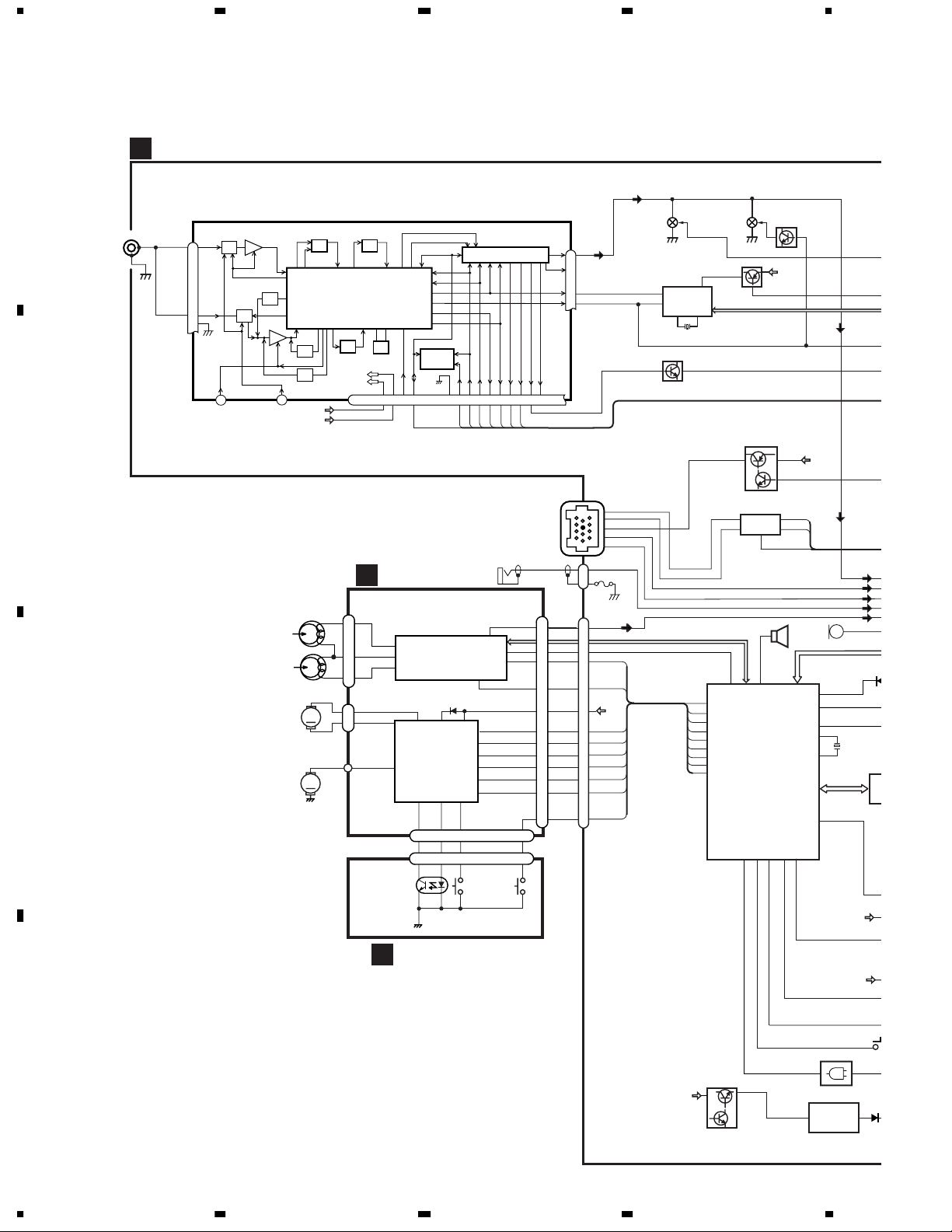
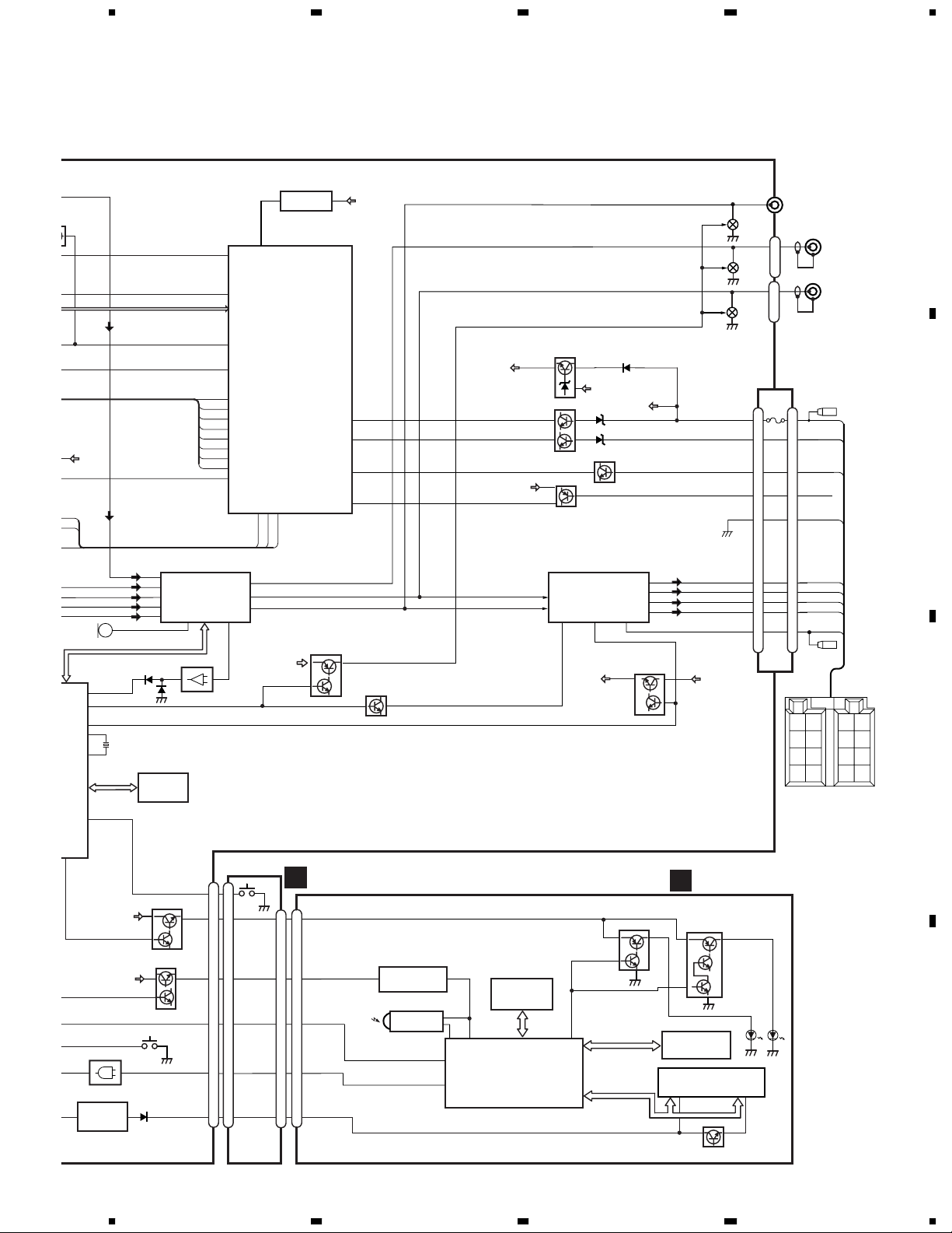
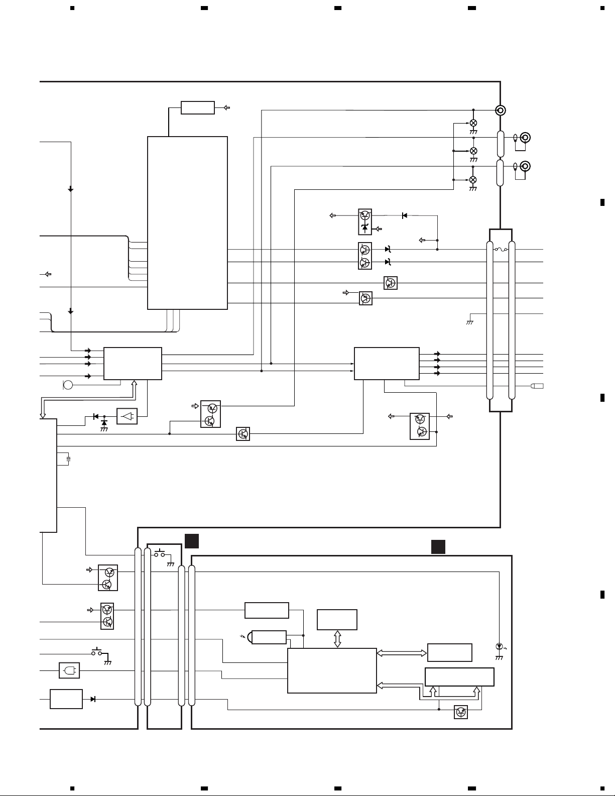
3. BLOCK DIAGRAM AND SCHEMATIC DIAGRAM
3.1 BLOCK DIAGRAM(KEH-P7020R/XN/EW)
TUNER AMP UNIT
A
A
FM/AM TUNER UNIT
ANT
CN401
1
2
FM/AM 1ST IF 10.7MHz
AMRF
AMANT
28
ATT
T51 Q51 CF51
ANT1 ADJ
FMANT
27
26
RFGND
ATT
FMRF
RF ADJ
ANT2 ADJ
LOCH
23
LOCL
MIXER, IF AMP, DET.
CF202
AM 2ND IF
450kHz
VCC
VDD
CF52 CF53
IC1
VDD
VCC
MPXREF 41kHz
AMDET
IC 2 FM MPX
CREQ
19
DI/DO
IC 3
EEPROM
NC
FMLOCL
924
DGND
11
CE2CKCE1
SDBWSLFMSD
X901
10.25MHz
NCNCWC
222510 14 12 15 16 8 13 2 3 4
20177
L ch
6
R ch
5
COMP
21
LDET
18
STIND
NL1
NL2
1
B
CN101
CN451
D
DECK UNIT
CN252
FWD
L-ch
REV
L-ch
M2
SUB
MOTOR
C
M1
MAIN
MOTOR
1
37
36
5
39
4
EQ AMP
HA12228F
CN254
2
M
1
CN255
5
2
MECHANISM
1
18
DRIVER
IC351
PA2020A
M
8
CN253
3
3
CN256
EGN1
REEL
SENSE
TEL
CN251
6
IC251
7
10
15 6
15 6
S2
MODE
16
17
MUTE
20
19
11
POS
13
NES
14
SC2
15
SC1
16
stby
17
LOAD
S1
LOAD
Lch
MS
f/R
B.U
CM
2
FUSE
1
200mA
3
5
6
9
20
13
15
16
17
18
19
1
11
CN251
DIRO
RIMUTE
POS
ES
SC2
SC1
CM
STBY
LOADSW
3
5
6
9
20
13
15
16
17
18
19
11
5
1
8
7
11
BU
Q153 Q151
RDS
DECODER
IC 501
PM4009A
Q402
24
1211
X501
SWDACC
20
8
IP-BUS DRIVER
BUSBUS+
BUS+L
BUS-L
54
MSIN
33
RIMUTE
55
DIRO
58
LOADSW
59
POS
61
ES
63
SC2
65
SC1
66
CM
68
STBY
SYSTEM CONTROLLER
Q501
Q101
Q102
5
IC 101
6
HA12187FP
BUZZER
IC 601(2/2)
PD5698B
KYDT
36
41
PEE
DSENS
Q155
VDD
BU
TX
1
RX
2
8
IPPW
TUN L
BUS+L
BUS-L
TEL
TAPE L
MIC751
VST,V
LEVEL IN
24
SWVDD
DPDT
35
40
43
LVLINL
MUTE
SYSPW
XOUT
EJTIN
ILMPW
94
87
23
13
X601
15
XIN
P
44
BU
REEL SENSE PCB
E
BU
DS
D
Q851
BU
Q852
14
KEH-P7020R
IC 801
24
TC7SET08FU
61
IC 851
NJM2360M
1234
Page 3
A
B
5678
RESET
IC 961
2
BSENS
ASENS
ISENS
TELIN
VDD
73
74
83
10
RL
PL
FL
VDD REGULATOR
BACKUP SENSE
Q931
ACC SENSE
VDD
Q911
Q951
ACC
Q932
BU
ACC
ILL SENSE
BU
VDD
TELEPHONE MUTE
1
S-80735ANDZI
12
52
TMUTE
RESET
48
FM/AM
SYSTEM CONTROLLER
IC 601(1/2)
PD5698B
19
LDET
51
NL2DT
95
NL1
50
SD
97
SL
53
SDBW
72
TUNPCE
2
TUNPCK
BU
TX
RX
71
82
1
TUNPCE2
TUNPDO
ASENBO
TXRXIPPW
30 29 81
Q351
RL
Q352
FL
5
Q353
CN901
FUSE
2
10A
3
5
8
11
CN351
R L
CN352-1
1
CN352-2
PL
FL
2
BACK UP
3
ACC
5
ILL
8
TELMUTE
GND
TUN L
BUS+L
BUS-L
TEL
TAPE L
MIC751
42
43
44
40
41
VST,VCK,VDT
LEVEL INDICATOR
94
LVLINL
87
MUTE
23
SYSPW
13
XOUT
X601
15
XIN
IC 631
LER
EJTIN
ILMPW
44
IC 801
PDH0046A
BU
BU
S801
DSENS
24
TC7SET08FU
61
IC 851
NJM2360M
ELECTRONIC VOLUME/
SOURCE SELECTOR
IN3-L
IN4+L
IC 203
IN4-L
PML009A
IN1-L
IN2-L
MIC_IN
SEL_OUT_L
1
13
IC 132
57
NJM4558MD
CN801
8
DPDT
KYDT
OELB
8
ILB
7
7
2
2
11
11
14
14
10
10
Q803
Q804
Q802
SWDVDD
Q801
CN1850
PL
FL
RL
EJECT
CN1851
12
10
11
S1850
B.U
B
CN1901
ILB
9
4
SWVDD
11
2
DPDT
3
10
KYDT
5
8
OELB
8
5
MUTE
Q982
MUTE
Q301
PANEL UNIT
REMOTE CONTROL SENSOR
OPT IN
3.3V REGULATOR
IC 1904
S-818A33AUC-BGN
IC 1903
TSOP1840SB3V
15
3
1
5
27
DPDT
28
KTDT
14
VDD
REM
OEL CONTROLLER/
KEY CONTROLLER
FONT ROM
IC 1902
PD8088A
IC 1901
PD5706A
14
FLIN
12
RLIN
22 4
KEY DATA
OEL DATA
POWER AMP
PAL007A
SYS+B
SYSPW
ILMD
32
IC 301
STBYMUTE
23
FL-
21
FL+
3
RL-
5
RL+
B.REMOTE
25
SYS+B REGULATOR
Q921
Q922
Q1961
Q1962
BU
KEYBOARD UNIT
C
Q1963
Q1964
Q1965
AMBER
KEY MATRIX
OEL UNIT
4,16
Q1941
10
12
11
GREEN
2,8
10
FL-
12
FL+
9
9
6
11
6
BACK
GND
RL-
RL+
B.REM
RR
RR
+
FR
REM
ACC
FR
+
-
B.
FL
FL
+
RL
RL
+
-
C
UP
ILL
D
KEH-P7020R
56
15
7
8
Page 4
1234
C
E
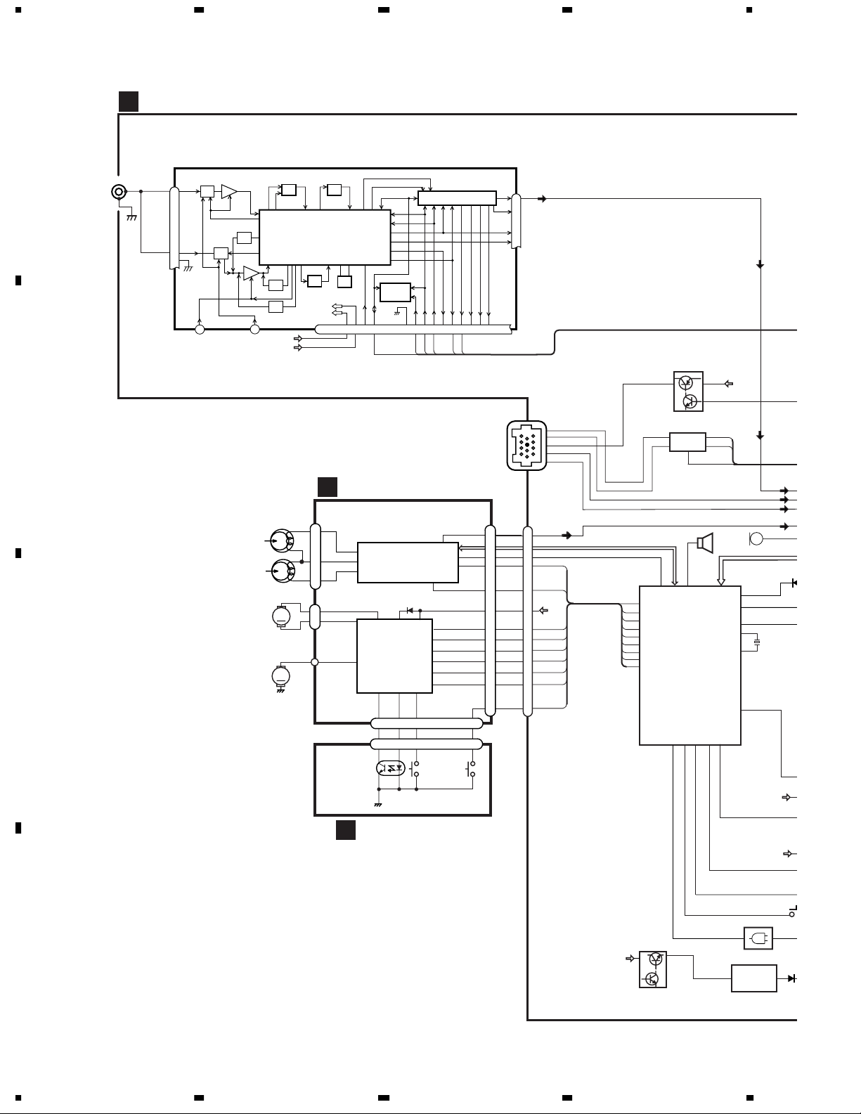
3.2 BLOCK DIAGRAM(KEH-P7025/XN/ES)
TUNER AMP UNIT
A
A
ANT
CN401
1
2
FM/AM TUNER UNIT
AMANT
28
ATT
FMANT
27
RFGND
26
LOCH
23
AMRF
ANT1 ADJ
ATT
FM/AM 1ST IF 10.7MHz
T51 Q51 CF51
FMRF
RF ADJ
ANT2 ADJ
LOCL
MIXER, IF AMP, DET.
CF202
AM 2ND IF
450kHz
VCC
VDD
CF52 CF53
IC1
X901
10.25MHz
VDD
VCC
CREQ
NCNCWC
222510 14 12 15 16 8 13 2 3 4
19
20177
MPXREF 41kHz
AMDET
IC 3
EEPROM
NC
FMLOCL
DGND
DI/DO
924
11
CE2CKCE1
IC 2 FM MPX
SDBWSLFMSD
L ch
6
R ch
5
COMP
21
LDET
18
STIND
NL1
NL2
1
SWDACC
Q101
BU
Q102
IP-BUS DRIVER
5
IC 101
6
HA12187FP
8
IPPW
BUZZER
24
54
PEE
MSIN
RIMUTE
DIRO
LOADSW
POS
ES
SC2
SC1
CM
STBY
SYSTEM CONTROLLER
IC 601(2/2)
PD5698B
DPDT
KYDT
DSENS
40
35
36
41
1
2
SWVDD
43
TX
RX
LVLINL
MUTE
SYSPW
XOUT
EJTIN
ILMPW
TUN L
BUS+L
BUS-L
TAPE L
MIC751
VST,V
LEVEL IND
94
87
23
13
X601
15
XIN
44
BU
CN251
16
17
MUTE
stby
LOAD
LOAD
B.U
POS
NES
SC2
SC1
S1
CN101
5
1
8
7
11
BUSBUS+
BUS+L
BUS-L
Lch
3
MS
5
f/R
6
9
20
13
15
16
17
CM
18
19
11
3
5
6
9
20
13
15
16
17
18
19
1
11
CN251
DIRO
RIMUTE
POS
ES
SC2
SC1
CM
STBY
LOADSW
33
BU
55
58
59
61
63
65
66
68
B
DECK UNIT
D
CN252
FWD
L-ch
REV
L-ch
M2
SUB
MOTOR
M1
MAIN
C
MOTOR
1
37
36
5
39
4
EQ AMP
HA12228F
6
IC251
20
CN254
2
M
1
CN255
5
2
MECHANISM
1
DRIVER
M
8
CN253
3
3
CN256
EGN1
REEL
SENSE
19
18
IC351
PA2020A
11
13
14
15
16
17
7
10
15 6
15 6
S2
MODE
REEL SENSE PCB
E
BU
DS
IC 801
Q851
D
16
KEH-P7020R
BU
61
Q852
TC7SET08FU
IC 851
NJM2360M
24
1234
Page 5
A
B
5678
TX
RX
LVLINL
MUTE
SYSPW
XOUT
XIN
BU
TUN L
BUS+L
BUS-L
TAPE L
MIC751
LEVEL INDICATOR
94
87
23
13
X601
15
ELECTRONIC VOLUME/
SOURCE SELECTOR
42
IN3-L
43
IN4+L
44
IN4-L
41
IN2-L
MIC_IN
VST,VCK,VDT
IC 203
PML009A
SEL_OUT_L
13
IC 132
NJM4558MD
SYSTEM CONTROLLER
50
SD
97
SL
72
TUNPCE
2
TUNPCK
71
TUNPCE2
1
TUNPDO
82
ASENBO
TXRXIPPW
30 29 81
12
PL
10
FL
11
RL
1
57
1
S-80735ANDZI
12
RESET
IC 601(1/2)
PD5698B
B.U
RESET
IC 961
BSENS
ASENS
MUTE
Q982
2
ISENS
TELIN
73
74
83
10
VDD
MUTE
Q301
RL
PL
FL
Q351
Q352
Q353
CN351
R L
CN352-1
RL
1
FL
5
PL
FL
CN352-2
VDD REGULATOR
VDD
Q911
BACKUP SENSE
Q931
ACC SENSE
Q951
VDD
TELEPHONE MUTE
14
FLIN
12
RLIN
22 4
SYSPW
ACC
ACC
Q932
ILL SENSE
POWER AMP
IC 301
PAL007A
STBYMUTE
B.REMOTE
25
SYS+B REGULATOR
SYS+B
FL+
RL-
RL+
Q922
CN901
BU
BU
23
FL-
21
3
5
Q921
BU
FUSE
2
2
10A
3
3
5
5
8
8
11
10
10
12
12
9
9
11
11
6
6
BACK UP
ACC
ILL
TELMUTE
GND
FLFL+
RL-
RL+
B.REM
LER
44
EJTIN
ILMPW
BU
BU
S801
DSENS
IC 801
24
TC7SET08FU
61
IC 851
NJM2360M
Q803
Q804
Q802
CN801
SWDVDD
Q801
DPDT
KYDT
OELB
S1850
8
8
EJECT
ILB
7
7
2
2
11
11
14
14
10
10
CN1851
CN1850
B
CN1901
ILB
9
4
SWVDD
11
2
DPDT
3
10
KYDT
5
8
OELB
8
5
PANEL UNIT
REMOTE CONTROL SENSOR
OPT IN
3.3V REGULATOR
IC 1904
S-818A33AUC-BGN
IC 1903
TSOP1840SB3V
15
3
1
5
27
DPDT
28
KTDT
14
VDD
REM
OEL CONTROLLER/
KEY CONTROLLER
FONT ROM
IC 1902
PD8088A
IC 1901
PD5706A
KEH-P7020R
56
KEY DATA
OEL DATA
C
KEYBOARD UNIT
C
GREEN
KEY MATRIX
OEL UNIT
Q1941
2,8
D
4,16
17
7
8
Page 6
A-a
A-b
A-b
A-a
C
1234
3.3 OVERALL CONNECTION DIAGRAM(GUIDE PAGE)(KEH-P7020R/XN/EW)
Note: When ordering service parts, be sure to refer to " EXPLODED VIEWS AND PARTS LIST" or
"ELECTRICAL PARTS LIST".
PDH0046A
IP-BUS
IP-BUS:+2.2dBs
111098
765
4321
ELE
SOU
0R0
FM: -16.5dBs
AM: -27.0dBs
IP-BUS: +2.2dBs
TAPE:-11.24dBs
100K
1K
0R0
A
CN251
D
Symbol indicates a resistor.
No differentiation is made between chip resistors and
discrete resistors.
Symbol indicates a capacitor.
No differentiation is made between chip capacitors and
discrete capacitors.
Decimal points for resistor
and capacitor fixed values
are expressed as :
2.2 2R2
0.022 R022
CN451
TAPE:-11.2dBs
>
HANDSFREE
NOTE :
The > mark found on some component parts indicates
the importance of the safety factor of the part.
Therefore, when replacing, be sure to use parts of
identical designation.
Large size
SCH diagram
A-a
A-b
Guide page
Detailed page
A-b
A-a A-b
A-a
TEL
B
←
←
A-a
IP-BUS
DRIVER
PANEL UNIT
B
EJECT
47K
231
NC
NR
RIMUTE
SYSTEM CONTROLLER
MSIN
DIRO
PLAY
MTLSW
LOADSWESNC
POS
SC2
4
SC1CMNC
NC
STBY
NC
AM(30%):-26.0dBs
FM(100%):-15.5dBs
FM/AM TUNER UNIT
C
ANTENNA
JACK
RDS DECODER
CN1901
KEYBOARD UNIT
C
D
A B
18
1234
KEH-P7020R
Page 7
A
B
5678
A-b
TUNER AMP UNIT
ASL
A
FM: -16.5dBs
AM: -27.0dBs
US: +2.2dBs
PE:-11.24dBs
ELECTRONIC VOLUME,
SOURCE SELECTOR
0R0
PML009A
0R0
EMUTE
10K(B)
FM: +6.6dBs
AM: -1.9dBs
IP-BUS: +9.3dBs
TAPE:-4.14dBs
RESET
LEVEL INDICATOR
MUTE
PAL007A
POWER AMP
MUTE
MUTE
MUTE
FM:+14.1dBs
AM: +0.6dBs
IP-BUS:+14.9dBs
TAPE:+1.36dBs
1
2
REAR
R CH
4
REAR
L CH
3
L CH
R CH
FRONT
L CH
FRONT
R CH
SYSTEM CONTROLLER
ESNCPOS
SC2
SC1CMNC
STBY
NC
NC
NC
NC
NC
NC
NC
SYS+B REGULATOR
VDD REGULATOR
1R5K
1R5K
MUTE
DC/DC CONVERTER
600µH
ILL SENSE
BSENSE
ASENSE
TEL
CEK1136
>
2
FUSE 10A
1
4
3
6
5
8
7
10
9
12
11
14
13
16
15
BACK
UP
ILL
REM
ACC
GND
FM: +32.6dBs
AM: +24.1dBs
IP-BUS: +35.3dBs
TAPE:+21.86dBs
2
BACK UP
1
GND
4
3
ACC
6
B.REM
5
ILL
8
TEL MUTE
7
10
FL-
9
RL-
12
FL+
11
RL+
14
FR-
13
RR-
16
FR+
15
RR+
RR
RR
+
FR
FR
+
-
B.
FL
FL
+
RL
RL
+
-
C
D
KEH-P7020R
56
A
19
7
8
Page 8
N
1234
A
4321
111098
765
B
IP-BUS:+2.2dBs
IP-BUS
IP-BUS
DRIVER
FM: -16.5dBs
AM: -27.0dBs
TAPE:-11.24dBs
IP-BUS: +2.2dBs
1
100K
1K
PDH0046A
47K
A-b
A-b
A-a
A-a
←
←
Decimal points for resistor
and capacitor fixed values
are expressed as :
2.2 2R2
0.022 R022
C
CN251
D
Symbol indicates a resistor.
No differentiation is made between chip resistors and
discrete resistors.
Symbol indicates a capacitor.
No differentiation is made between chip capacitors and
discrete capacitors.
The > mark found on some component parts indicates
the importance of the safety factor of the part.
Therefore, when replacing, be sure to use parts of
HANDSFREE
NOTE :
>
D
TAPE:-11.2dBs
CN451
identical designation.
IT
AM(30%):-26.0dBs
FM(100%):-15.5dBs
20
A-a A-b
TEL
KEH-P7020R
1234
Page 9

A
B
O
STBY
5678
NC
CM
NCNRRIMUTE
1K
47K
SYSTEM CONTR
SC1
SC2
ES
NC
POS
LOADSW
MTLSW
PLAY
DIRO
MSIN
2
1
4
2
3
EJECT
PANEL UNIT
B
CN1901
C
KEYBOARD UNIT
A-b
A-b
A-a
A-a
C
AM(30%):-26.0dBs
FM(100%):-15.5dBs
56
FM/AM TUNER UNIT
JACK
ANTENNA
KEH-P7020R
RDS DECODER
D
B
A-a A-b
21
7
8
Page 10

U
1234
FRONT
L CH
R CH
L CH
FM:+14.1dBs
AM: +0.6dBs
TAPE:+1.36dBs
REAR
R CH
REAR
IP-BUS:+14.9dBs
A
L CH
1
3
2
4
FRONT
R CH
MUTE
MUTE
MUTE
TUNER AMP UNIT
A
POWER AMP
PAL007A
B
MUTE
A-b
A-a
LEVEL INDICATOR
RESET
FM: +6.6dBs
AM: -1.9dBs
C
10K(B)
ASL
PML009A
0R0
ELECTRONIC VOLUME,
D
SOURCE SELECTOR
A-b
22
KEH-P7020R
TAPE:-4.14dBs
IP-BUS: +9.3dBs
FM: -16.5dBs
AM: -27.0dBs
0R0
1
-BUS: +2.2dBs
TAPE:-11.24dBs
TE
1234
Page 11

A
B
LOADSW
5678
+
+
+
+
RL
FL
FR
ACC
GND
BACK UP
2143658
CEK1136
FUSE 10A
>
2143658
600µH
B.REM
ILL
TEL MUTE
7109
7109
FL-
RL-
FL+
1211141316
1211141316
FR-
RR-
RL+
ILL SENSE
FR+
RR+
15
15
BSENSE
RR
-
-
FR
RR
UP
BACK
ASENSE
FL
B.
ILL
-
RL
ACC
REM
GND
-
FM: +32.6dBs
AM: +24.1dBs
TAPE:+21.86dBs
IP-BUS: +35.3dBs
POWER AMP
PAL007A
RESET
1R5K
1R5K
VDD REGULATOR
SYS+B REGULATOR
TEL
A-b
A-a
MUTE
C
NC
NC
NC
EMUTE
NC
NC
DC/DC CONVERTER
NC
NC
STBY
NC
CM
SC1
SC2
SYSTEM CONTROLLER
ES
NC
POS
2
KEH-P7020R
56
D
A-b
23
7
8
Page 12

O
1234
3.4 OVERALL CONNECTION DIAGRAM(GUIDE PAGE)(KEH-P7025/XN/ES)
IP-BUS
IP-BUS:+2.2dBs
111098
765
4321
EL
S
0R0
FM: -20.5dBs
AM: -31.0dBs
IP-BUS: +2.2dBs
TAPE:-11.24dBs
0R0
A
CN251
TAPE:-11.2dBs
B
NOTE :
D
Symbol indicates a resistor.
No differentiation is made between chip resistors and
discrete resistors.
Symbol indicates a capacitor.
No differentiation is made between chip capacitors and
discrete capacitors.
The > mark found on some component parts indicates
the importance of the safety factor of the part.
Therefore, when replacing, be sure to use parts of
identical designation.
A-a
Decimal points for resistor
and capacitor fixed values
are expressed as :
←
2.2 2R2
←
0.022 R022
IP-BUS
DRIVER
AM(30%):-30.0dBs
FM(100%):-19.5dBs
FM/AM TUNER UNIT
C
ANTENNA
JACK
R018R018
NC
NR
RIMUTE
SYSTEM CONTROLLER
NC
SC2
SC1CMNC
STBY
NC
CN1901
PANEL UNIT
B
EJECT
231
MSIN
DIRO
PLAY
MTLSW
LOADSWESNC
POS
4
KEYBOARD UNIT
C
D
A B
24
1234
KEH-P7020R
Page 13

A
B
5678
A-b
TUNER AMP UNIT
ASL
A
FM: -20.5dBs
AM: -31.0dBs
-BUS: +2.2dBs
TAPE:-11.24dBs
ELECTRONIC VOLUME,
SOURCE SELECTOR
0R0
PML009A
0R0
EMUTE
10K(B)
FM: +2.6dBs
AM: -7.9dBs
IP-BUS: +7.3dBs
TAPE:-6.14dBs
RESET
LEVEL INDICATOR
MUTE
PAL007A
POWER AMP
MUTE
MUTE
MUTE
FM:+10.1dBs
AM: -0.4dBs
IP-BUS:+14.9dBs
TAPE:+1.36dBs
1
2
REAR
R CH
4
REAR
L CH
3
L CH
R CH
FRONT
L CH
FRONT
R CH
SYSTEM CONTROLLER
LOADSWESNC
POS
SC2
SC1CMNC
NC
NC
NC
STBY
NC
NC
NC
NC
SYS+B REGULATOR
VDD REGULATOR
1R5K
1R5K
MUTE
DC/DC CONVERTER
600µH
ILL SENSE
BSENSE
ASENSE
CEK1136
>
2
FUSE 10A
1
4
3
6
5
8
7
10
9
12
11
14
13
16
15
FM: +28.6dBs
AM: +18.1dBs
IP-BUS: +33.3dBs
TAPE:+19.86dBs
10
12
11
14
13
16
15
2
1
4
3
6
5
8
7
9
BACK UP
TEL MUTE
GND
ACC
B.REM
ILL
FLRLFL+
RL+
FRRRFR+
RR+
C
TEL
D
KEH-P7020R
56
A
25
7
8
Page 14

N
1234
A
4321
111098
765
IP-BUS:+2.2dBs
B
IP-BUS
IP-BUS
DRIVER
FM: -20.5dBs
AM: -31.0dBs
TAPE:-11.24dBs
IP-BUS: +2.2dBs
1
A-b
A-b
A-a
A-a
←
←
Decimal points for resistor
and capacitor fixed values
are expressed as :
2.2 2R2
0.022 R022
C
CN251
D
R018R018
Symbol indicates a resistor.
No differentiation is made between chip resistors and
discrete resistors.
Symbol indicates a capacitor.
No differentiation is made between chip capacitors and
discrete capacitors.
The > mark found on some component parts indicates
the importance of the safety factor of the part.
Therefore, when replacing, be sure to use parts of
NOTE :
D
TAPE:-11.2dBs
identical designation.
IT
AM(30%):-30.0dBs
FM(100%):-19.5dBs
26
A-a A-b
KEH-P7020R
1234
Page 15

A
B
O
STBY
5678
NC
CM
SC1
SC2
ES
NC
POS
LOADSW
MTLSW
PLAY
DIRO
MSIN
2
1
4
2
3
EJECT
NCNRRIMUTE
SYSTEM CONTR
PANEL UNIT
B
CN1901
C
KEYBOARD UNIT
A-b
A-b
A-a
A-a
C
R018R018
AM(30%):-30.0dBs
FM(100%):-19.5dBs
FM/AM TUNER UNIT
JACK
ANTENNA
KEH-P7020R
56
D
B
A-a A-b
27
7
8
Page 16

U
1234
FRONT
L CH
R CH
L CH
FM:+10.1dBs
AM: -0.4dBs
TAPE:+1.36dBs
IP-BUS:+14.9dBs
A
REAR
R CH
REAR
L CH
1
3
2
4
FRONT
R CH
MUTE
MUTE
MUTE
TUNER AMP UNIT
A
POWER AMP
PAL007A
B
MUTE
A-b
A-a
LEVEL INDICATOR
RESET
FM: +2.6dBs
AM: -7.9dBs
C
10K(B)
ASL
PML009A
0R00R0
ELECTRONIC VOLUME,
D
SOURCE SELECTOR
A-b
28
KEH-P7020R
TAPE:-6.14dBs
IP-BUS: +7.3dBs
FM: -20.5dBs
AM: -31.0dBs
1
-BUS: +2.2dBs
TAPE:-11.24dBs
TE
1234
Page 17

A
B
5678
LOADSW
FL-
FR-
RL-
RR-
FL+
RL+
FR+
ILL SENSE
RR+
15
15
FM: +28.6dBs
AM: +18.1dBs
TAPE:+19.86dBs
IP-BUS: +33.3dBs
BSENSE
ASENSE
ACC
GND
BACK UP
2143658
CEK1136
FUSE 10A
>
2143658
600µH
B.REM
ILL
TEL MUTE
7109
7109
1211141316
1211141316
POWER AMP
PAL007A
RESET
1R5K
1R5K
VDD REGULATOR
SYS+B REGULATOR
TEL
A-b
A-a
MUTE
C
NC
NC
NC
EMUTE
NC
NC
DC/DC CONVERTER
NC
NC
STBY
NC
CM
SC1
SC2
SYSTEM CONTROLLER
ES
NC
POS
2
KEH-P7020R
56
D
A-b
29
7
8
Page 18

1234
3.5 KEYBOARD UNIT(KEH-P7020R/XN/EW)
B
CN1851
A
REMOTE CONTROL
SENSOR
3.3V REGULATOR
VOLUME
B
TA
1
2
3
1
2
3
6
5
4
6
5
4
1
2
3
6
5
4
DISP/SCRL ENT
1
2
3
1
2
3
6
5
4
6
5
4
1
2
3
1
2
3
6
5
4
6
5
4
TEXT
1
2
3
6
5
4
1
2
3
6
5
4
1
2
3
6
5
4
1
2
3
6
5
4
SFEQ
C
←
1
2
3
6
5
4
BAND/ESC
1
2
3
D
6
5
4
←
1
2
3
6
5
4
←
1
2
3
6
5
4
1
2
3
←
1
2
3
6
5
4
6
5
4
1
2
3
6
5
4
C
30
1234
KEH-P7020R
Page 19

A
B
5678
KEYBOARD UNIT
C
FONT ROM
KEY CONTROL AND OEL CONTROL
C
OEL UNIT MXS8017
56
KEH-P7020R
D
C
31
7
8
Page 20

1234
3.6 KEYBOARD UNIT(KEH-P7025/XN/ES)
B
CN1851
A
REMOTE CONTROL
SENSOR
3.3V REGULATOR
VOLUME
DISP/SCRL CLK
1
2
3
1
2
3
6
5
4
6
5
4
1
2
3
1
2
3
6
5
4
6
5
4
1
2
3
1
2
3
ENT
6
5
4
6
5
4
1
2
3
6
5
4
B
PAUSE
1
2
3
6
5
4
1
2
3
6
5
4
1
2
3
6
5
4
1
2
3
6
5
4
SFEQ
C
←
1
2
3
6
5
4
BAND/ESC
1
2
3
D
6
5
4
←
1
2
3
6
5
4
←
1
2
3
6
5
4
1
2
3
←
1
2
3
6
5
4
6
5
4
1
2
3
6
5
4
C
32
1234
KEH-P7020R
Page 21

A
B
5678
KEYBOARD UNIT
C
FONT ROM
KEY CONTROL AND OEL CONTROL
PD8088A
C
OEL UNIT MXS8017
56
KEH-P7020R
D
C
33
7
8
Page 22

1234
3.7 CASSETTE MECHANISM MODULE
A
D
DECK UNIT
CN252
B
RL
RR
Rev-L
Rev-R
Fwd-R
FR
FL
HD1
HEAD ASSY
EXA1589
TEST TAPE
NCT-150
(400Hz, 200nWb/m)
Fwd-L
C254
390P
C253
C251
C252
390P
390P
390P
C256
C255
R01
R1
VR302
33K(B)
CCP1280
R01
31
32
33
34
35
36
37
38
39
40
NF1(R)
Vref1
RIN(L)
NC
RIN(R)
GND
FIN(R)
Vref2
FIN(L)
NFI(L)
30
MOUT(R)
M-OUT(L)
1
VR301
33K(B)
292827
EQOUT(R)
EQOUT(L)
234
CCP1280
1/50
C271
R1
C302
26
252423
NC
RIP
Vref3
TAI(R)
PBOUT(R)
IC251
HA12228F
Dolby-B
NC
PBOUT(L)
Vref4
TAI(L)
BIAS
5
678
R1
C301
18K
C309
R271
C310
DET(R)
NC
9
R1
22
NC
NC
21
MSGV(S)
10
R401
C401
NRONoff
MUTE
120/70
ser/REP
MSOUT
MSDET
MAOUT
MSGV(R)
15K
3900P
20
19
18
17
f/R
16
15
VCC
14
13
MSI
12
11
C404
R403
R402
C402
R404
R01
3R3K
R33
C405
R033
270K
910
R022
C403
C
C272
R1
R285 0R0
CN251
MUTE
-8.24dBs±1dB
A
CN251
D
D
34
1234
KEH-P7020R
Page 23

A
B
5678
9
M1 MOTOR UNIT
(MAIN MOTOR)
EXA1490
CN255
S3
S2
S1
REEL SENSE
70µs
MODE
LOAD
PCB
EGN1
EGN1004
ESG1007
ESG1007
ESG1007
CN253
R375
0R0
R373 0R0
MECHANISM
DRIVER
MCS
RS3
RRS
RS2
FRS
RS1
RSB
C405
R033
270K
1
10
R022
C403
SC2
SC1
TAB
MC
CE
VCC2
VCC
NC
C
TAB
MS2
NC
NC
IC351 PA2020A
SM1
MM
R355 270K
R374 0R0
3900P
C352
R362 300
CN254
C351 R22
CN256
RSB
GND
RS
mtl
MCS
load
REEL SENSE
E
M2
MOTOR UNIT
(SUB MOTOR)
EXA1580
R351 1K
R353 1K
R352 1K
R354 1K
C356 R01
C354 R01
C353 R01
C
SWITCHES:
D352 1SS355
C355 R1
REEL SENSE PCB
S1:LOAD SWITCH..........EJECT-PLAY
S2:MODE SWITCH............ON-OFF
S3:70µs SWITCH............ON-OFF
The underlined indicates the switch position.
D
KEH-P7020R
56
ED
35
7
8
Page 24

1234
7.1.2 CONNECTOR FUNCTION DESCRIPTION
A
- KEH-P7020R/XN/EW
SUB WOOFER
OR
NON-FADING OUTPUT
FRONT
OUTPUT
B
8 9 10 11
56 7
1234
1516131411129107856341
2
ANTENNA
2. GND
3. GND
1. BUS+
REAR
OUTPUT
C
4. NC
5. BUS-
6. GND
7. BL+
8. ASENB
9. BR+
10. BR-
11. BL-
IP-BUS
1. GND
2. B.UP
3. ACC
4. NC
5. ILL
6. B.REM
7. NC
8. MUTE
9. RL-
10. FL-
11. RL+
12. FL+
13. RR-
14. FR-
15. RR+
16. FR+
POWER SUPPLY
TEL
D
58
1234
KEH-P7020R
 Loading...