

Page 1
MANUEL D’INSTALLATION
KEH-P7020R
INSTALLATION MANUAL
ENGLISH
ESPAÑOL
DEUTSCH
FRANÇAIS
ITALIANO
NEDERLANDS
This product conforms to new cord colors.
Los colores de los cables de este producto se conforman con un nuevo código de colores.
Dieses Produkt entspricht den neuen kabelfarben.
Le code de couleur des câbles utilisé pour ce produit est
nouveau.
Questo prodotto è conforme ai nuovi codici colori.
De kleuren van de snoeren van dit toestel zijn gewijzigd.
Page 2

1
Connecting the Units ................................ 1
Installation .................................................. 5
Installation with the rubber bush ...................... 5
Removing the Unit ............................................ 6
Fixing the Front Panel ...................................... 7
Installing the
Steering Remote Control Unit .......... 9
Installing the Unit on a
Left-Hand-Drive Car ................................ 10
Connecting the Units
Contents
Note:
• This unit is for vehicles with a 12-volt battery and
negative grounding. Before installing it in a recreational vehicle, truck, or bus, check the battery
voltage.
• To avoid shorts in the electrical system, be sure to
disconnect the ≠ battery cable before beginning
installation.
• Refer to the owner’s manual for details on connecting the power amp and other units, then make
connections correctly.
• Secure the wiring with cable clamps or adhesive
tape. To protect the wiring, wrap adhesive tape
around them where they lie against metal parts.
• Route and secure all wiring so it cannot touch any
moving parts, such as the gear shift, handbrake,
and seat rails. Do not route wiring in places that
get hot, such as near the heater outlet. If the insulation of the wiring melts or gets torn, there is a
danger of the wiring short-circuiting to the vehicle body.
• Don’t pass the yellow lead through a hole into the
engine compartment to connect to the battery.
This will damage the lead insulation and cause a
very dangerous short.
• Do not shorten any leads. If you do, the protection circuit may fail to work when it should.
• Never feed power to other equipment by cutting
the insulation of the power supply lead of the unit
and tapping into the lead. The current capacity of
the lead will be exceeded, causing overheating.
• When replacing fuse, be sure to use only fuse of
the rating prescribed on this unit.
• Since a unique BPTL circuit is employed, never
wire so the speaker leads are directly grounded or
the left and right ≠ speaker leads are common.
Page 3
• Speakers connected to this unit must be highpower types with minimum rating of 50 W and
impedance of 4 to 8 ohms. Connecting speakers
with output and/or impedance values other than
those noted here may result in the speakers catching fire, emitting smoke, or becoming damaged.
• When this product’s source is switched ON, a
control signal is output through the blue/white
lead. Connect to an external power amp’s system
remote control or the car’s Auto-antenna relay
control terminal (max. 300 mA 12 V DC). If the
car features a glass antenna, connect to the antenna booster power supply terminal.
• When an external power amp is being used with
this system, be sure not to connect the blue/white
lead to the amp’s power terminal. Likewise, do
not connect the blue/white lead to the power terminal of the auto-antenna. Such connection could
cause excessive current drain and malfunction.
• To avoid short-circuiting, cover the disconnected
lead with insulating tape. Especially, insulate the
unused speaker leads without fail. There is a possibility of short-circuiting if the leads are not insulated.
• To prevent incorrect connection, the input side of
the IP-BUS connector is blue, and the output side
is black. Connect the connectors of the same colors correctly.
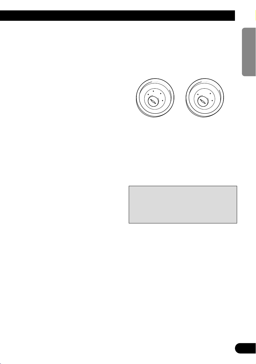
• If this unit is installed in a vehicle that does not
have an ACC (accessory) position on the ignition
switch, the red lead of the unit should be connected to a terminal coupled with ignition switch
ON/OFF operations. If this is not done, the vehicle battery may be drained when you are away
from the vehicle for several hours. (Fig. 1)
Fig. 1
• The black lead is ground. Please ground this lead
separately from the ground of high-current products such as power amps.
If you ground the products together and the
ground becomes detached, there is a risk of damage to the products or fire.
• Cords for this product and those for other products may be different colors even if they have the
same function. When connecting this product to
another product, refer to the supplied Installation
manuals of both products and connect cords that
have the same function.
No ACC positionACC position
2
ENGLISH ESPAÑOL DEUTSCH FRANÇAIS
ITALIANO NEDERLANDS
C
C
A
O
F
N
F
O
S
T
A
R
T
O
F
N
F
O
S
T
A
R
T
Page 4
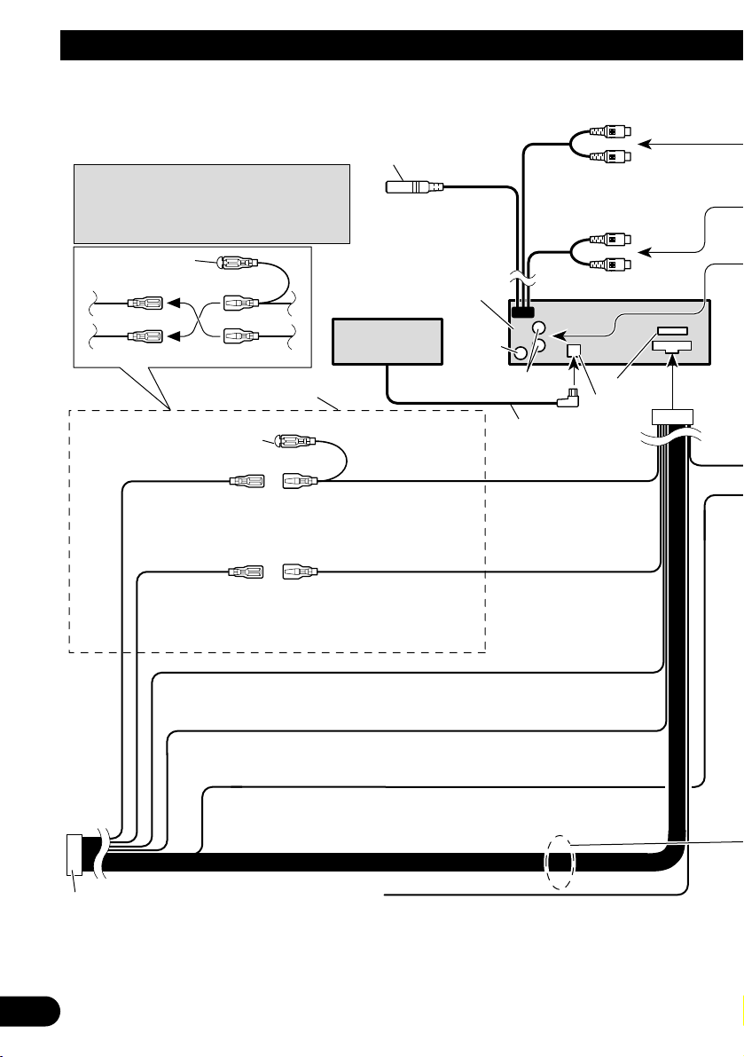
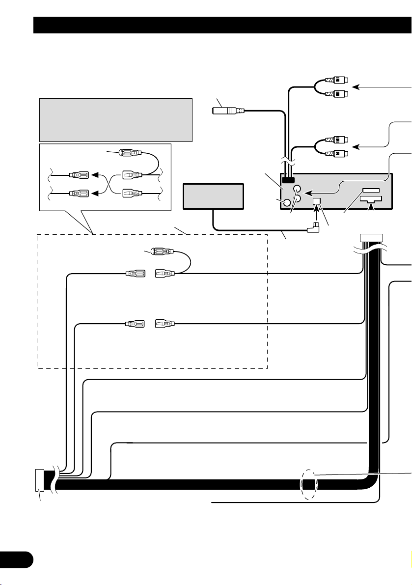
Note:
Depending on the kind of vehicle, the function
of 3* and 5* may be different. In this case, be
sure to connect 2* to 5* and 4* to 3*.
Cap (1*)
When not using this terminal,
do not remove the cap.
ISO connector
Fuse
1*
2*
4*
3*
5*
Yellow (2*)
To terminal always supplied
with power regardless of
ignition switch position.
Red (4*)
To electric terminal controlled
by ignition switch (12 V DC)
ON/OFF.
Yellow (3*)
Back-up
(or accessory)
Red (5*)
Accessory
(or back-up)
Black (ground)
To vehicle (metal) body.
Orange/white
To lighting switch terminal.
Connect leads of the same
color to each other.
Note:
In some vehicles, the ISO connector may be
divided into two. In this case, be sure to
connect to both connectors.
Multi-CD player
(sold separately)
IP-BUS cable
TEL terminal
Refer to a Handsfree Telephone Unit’s
manual (sold separately).
Subwoofer output
or Non Fading Output
IP-Bus input
(Blue)
Antenna
jack
Yellow/black
If you use a cellular telephone, connect it via the
Audio Mute lead on the cellular telephone. If not,
keep the Audio Mute lead free of any connections.
Front output
Rear output
This Product
16 cm
16 cm
16 cm
3
Connecting the Units
Page 5
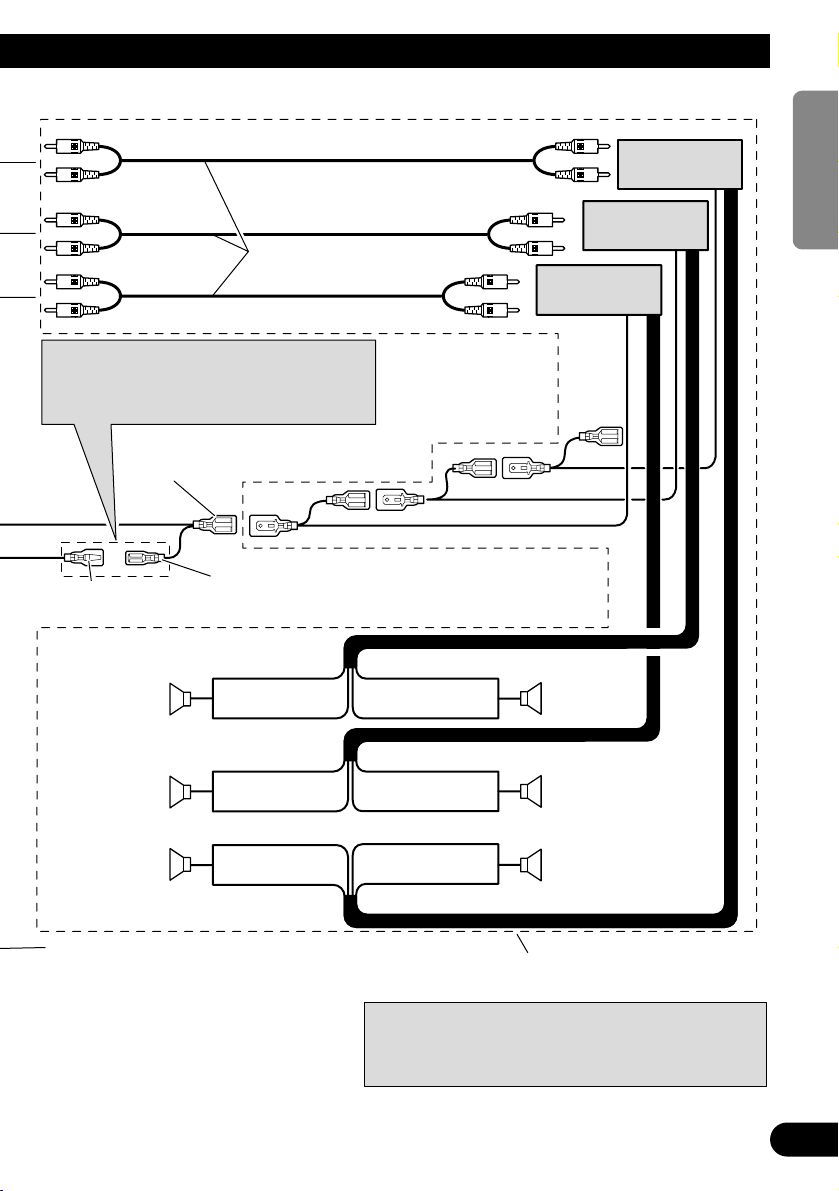
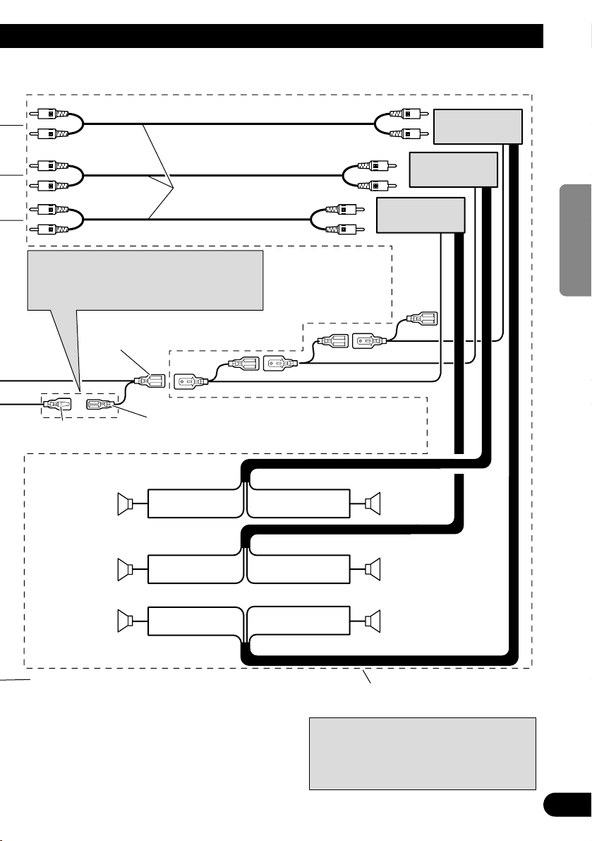
Speaker leads
Blue/white
To system control terminal of the power
amp (max. 300 mA 12 V DC).
Blue/white (7*)
To Auto-antenna relay control terminal
(max. 300 mA 12 V DC).
White
White/black
Gray
Gray/black
Green
Green/black
Violet
Violet/black
: Front left +
: Front left ≠
: Front right +
: Front right ≠
: Rear left + or Subwoofer +
: Rear left ≠ or Subwoofer ≠
: Rear right + or Subwoofer +
: Rear right ≠ or Subwoofer ≠
Use this for connections when you have the separately
available amplifier.
Blue/white (6*)
Connecting cords
with RCA pin plugs
(sold separately)
System remote control
Rear speaker
Subwoofer Subwoofer
Rear speaker
Front speakerFront speaker
The pin position of the ISO connector will differ
depends on the type of vehicle. Connect 6* and
7* when Pin 5 is an antenna control type. In
another type of vehicle, never connect 6* and 7*.
Note:
Change the Initial Setting of this Product (refer to the
Operation Manual). The subwoofer output of this unit is
monaural.
Left Right
Power amp
(sold separately)
Power amp
(sold separately)
≠
+
≠
+
+
≠
+
≠
≠
+
≠
+
Power amp
(sold separately)
4
ENGLISH ESPAÑOL DEUTSCH FRANÇAIS
ITALIANO NEDERLANDS
Fig. 2
Page 6
5
A Title (English)
Installation with the rubber bush
Fig. 4
Installation
Note:
• Before finally installing the unit, connect the
wiring temporarily, making sure it is all connected up properly, and the unit and the system work
properly.
• Use only the parts included with the unit to ensure
proper installation. The use of unauthorized parts
can cause malfunctions.
• Consult with your nearest dealer if installation
requires the drilling of holes or other modifications of the vehicle.
• Install the unit where it does not get in the driver’s way and cannot injure the passenger if there
is a sudden stop, like an emergency stop.
• The semiconductor laser will be damaged if it
overheats, so don’t install the unit anywhere hot
— for instance, near a heater outlet.
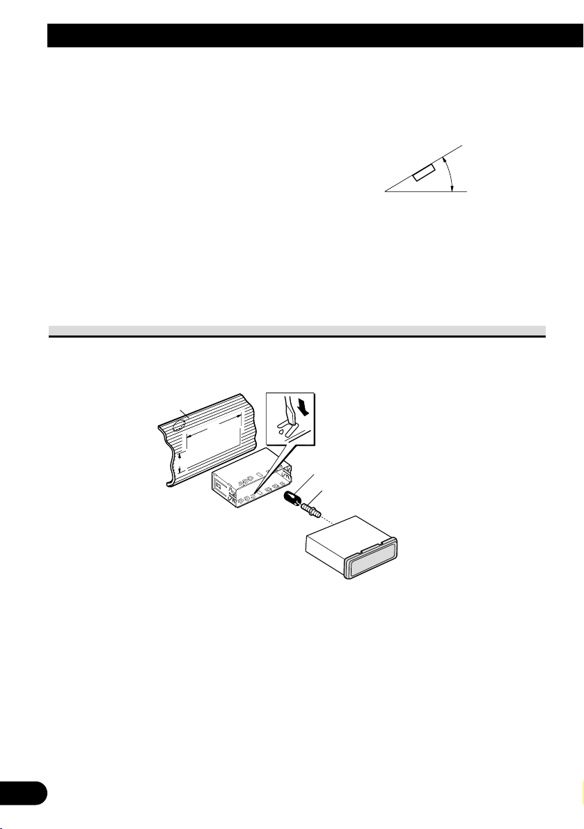
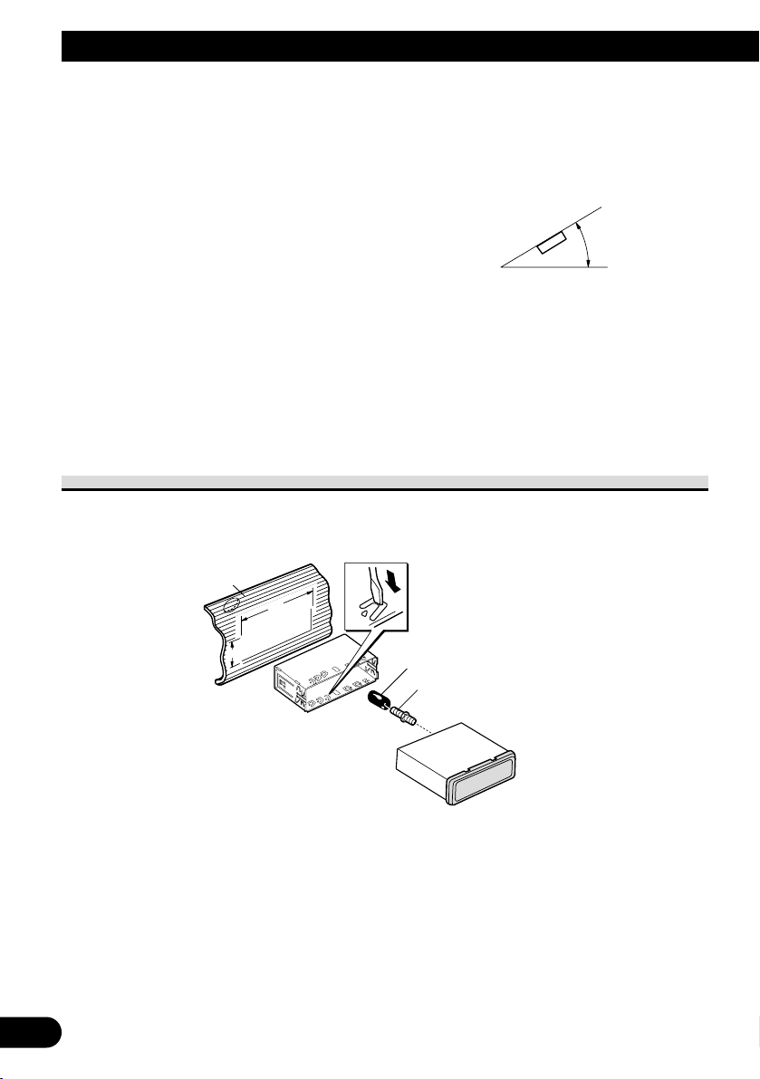
• If installation angle exceeds 30° from horizontal,
the unit might not give its optimum performance.
(Fig. 3)
Fig. 3
Dashboard
Holder
After inserting the holder into the dashboard, then select the appropriate tabs
according to the thickness of the dashboard material and bend them.
(Install as firmly as possible using the
top and bottom tabs. To secure, bend
the tabs 90 degrees.)
Rubber bush
Screw
182
53
30°
Page 7
A Title (English)
6
ENGLISH ESPAÑOL DEUTSCH FRANÇAIS
ITALIANO NEDERLANDS
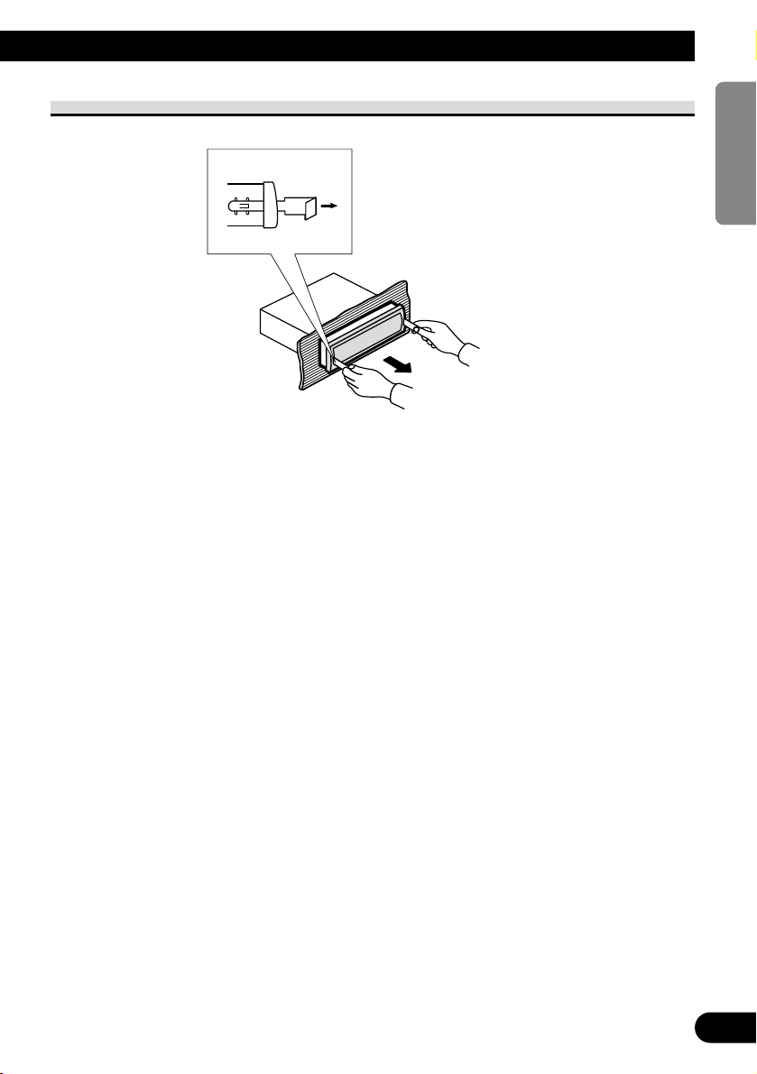
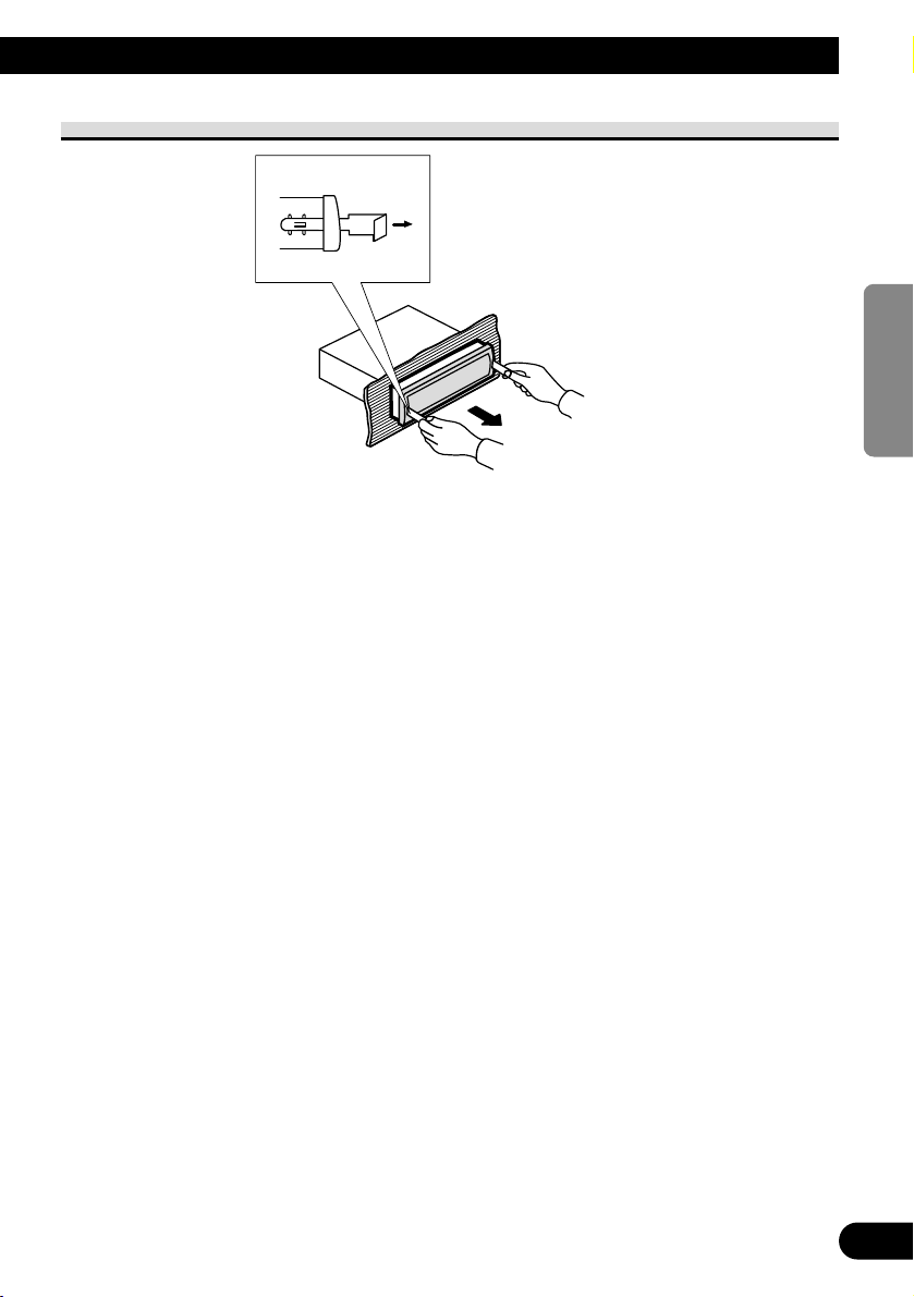
Removing the Unit
Fig. 5
Insert the supplied extraction keys
into the unit, as shown in the figure,
until they click into place. Keeping
the keys pressed against the sides of
the unit, pull the unit out.
Page 8
7
Installation
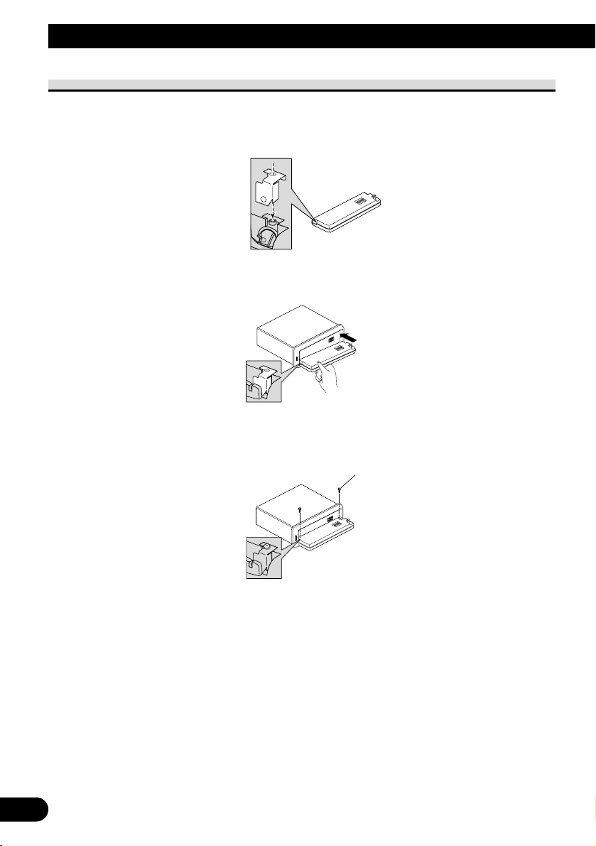
Fixing the Front Panel
If you do not operate the Detaching and Replacing the Front Panel Function, use the supplied fixing screws and holder to fix the front panel to this unit.
1. Attach the holder to the front panel. (Fig. 6)
Fig. 6
2. Replace the front panel to the unit. (Fig. 7)
Fig. 7
3. Fix the front panel to the unit using fixing screws. (Fig. 8)
Fig. 8
Fixing screw
Page 9

8
ENGLISH ESPAÑOL DEUTSCH FRANÇAIS
ITALIANO NEDERLANDS
Page 10
9
A Title (English)
WARNING
• Avoid installing this unit in such a location where
the operation of safety devices such as airbags is
prevented by this unit. Otherwise, there is a danger of a fatal accident.
• Avoid installing this unit in such a location where
the operation of the steering wheel and the
gearshift lever may be prevented. Otherwise, it
may result in a traffic accident.
CAUTION
• Installation of this unit requires specialized skills
and experience. Installation of this unit should be
entrusted to a dealer from whom you purchased
this unit.
• Install this unit using only the parts supplied with
this unit. If other parts are used, this unit may be
damaged or could dismount itself, which leads to
an accident or trouble.
• Install this unit as required by this manual.
Failure to do so may cause an accident.
• Do not install this unit near the doors where rainwater is likely to be spilled on the unit. Incursion
of water into the unit may cause smoke or fire.
WARNING
• Fix this unit securely to the steering wheel with
the belt attached to the unit. If this unit is loose, it
disturbs driving stability, which may result in a
traffic accident.
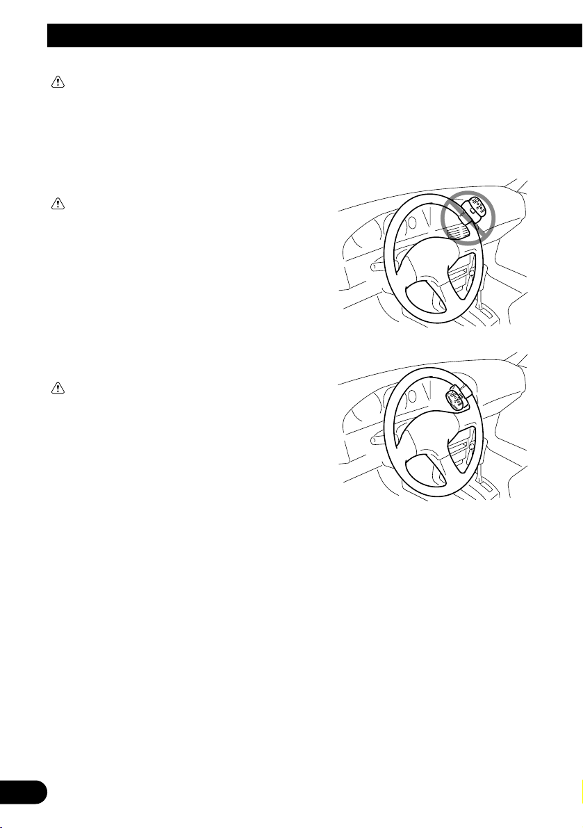
• Do not attach this unit to the outer circumference
of the steering wheel. Otherwise, it disturbs driving stability, causing a traffic accident. Always
attach this unit to the inner circumference of the
steering wheel as shown. (Fig. 9)
Note:
• Do not install this unit in such a place as may
obstruct the driver’s view.
• Since interior layout differs depending on the
type of vehicle, the ideal installation location for
the unit also differs. When installing the unit,
select a location that assures optimum transmission of signals from the unit to the car stereo.
Fig. 9
Installing the Steering Remote Control Unit
Page 11
10
ENGLISH ESPAÑOL DEUTSCH FRANÇAIS
ITALIANO NEDERLANDS
Installing the Unit on a Left-HandDrive Car
Note:
• When the unit is installed on a right-hand-drive
car, the horizontal positions are inverted.
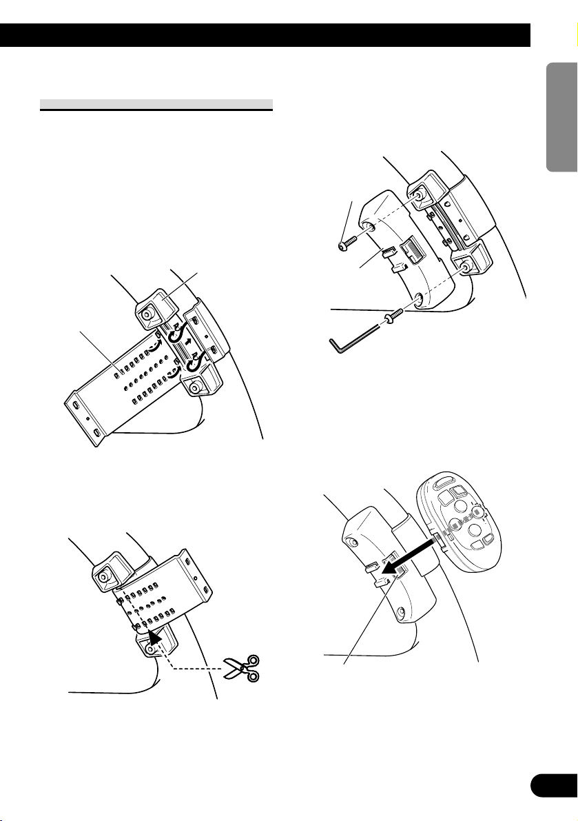
1. Secure inner holder to the inner cir-
cumference of the steering wheel
with belt. (Fig. 10)
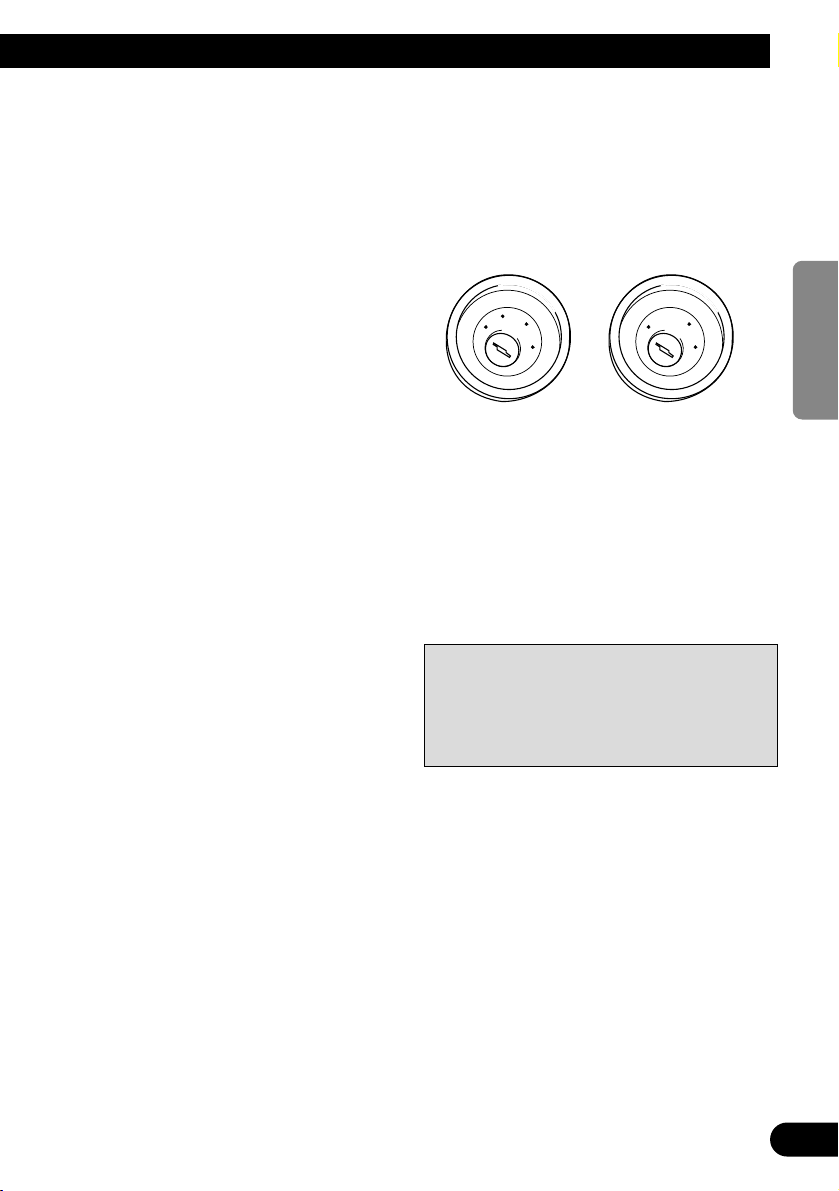
• Fit the inner holder to the steering wheel so
that the arrow-marked side faces the driver as
shown below.
Fig. 10
2. Cut the extra portion of the belt at
the center of the inner holder.
(Fig. 11)
Fig. 11
3. Install outer holder on the inner
holder and secure with screws.
(Fig. 12)
• Tighten the screws with the supplied hexago-
nal wrench.
Fig. 12
4. Install the remote control unit in
the holder. (Fig. 13)
• When removing the remote control unit from
the holder, move the corrugated release section toward the steering wheel and slide the
remote control unit toward you.
Fig. 13
Belt
Inner holder
Screw
Outer holder
Release Section
Page 12

1
Conexión de las unidades ........................ 1
Instalación .................................................. 5
Instalación con tope de goma ............................ 5
Extracción de la unidad .................................... 6
Colocación del panel delantero ........................ 7
Instalación de la unidad de control
remoto de dirección ............................ 9
Instalación de la unidad en
el coche de manejo del lado izquierdo ...... 10
Conexión de las unidades
Contenido
Nota:
• Esta unidad es para vehículos con batería de 12
voltios y con conexión a tierra. Antes de instalar
la unidad en un vehículo recreativo, camioneta, o
autobús, revise el voltaje de la batería.
• Para evitar cortocircuitos en el sistema eléctrico,
asegúrese de desconectar el cable de la batería ≠
antes de comenzar con la instalación.
• Consulte con el manual del usuario para los
detalles sobre la conexión de la alimentación de
amperios y de otras unidades, luego haga las
conexiones correctamente.
• Asegure el cableado con abrazaderas de cables o
con cinta adhesiva. Para proteger el cableado,
envuélvalo con cinta adhesiva donde éstos se
apoyan sobre las piezas de metal.
• Coloque y asegure todo el cableado de tal manera
que no toque las piezas en movimiento, tal como
la palanca de cambio de velocidades, el freno de
mano, y los pasamanos de los asientos. No
coloque el cableado en lugares que se calientan,
tal como cerca de la salida de un calefactor. Si el
material aislante del cableado se derritiera o se
gastara, habrá el peligro de un cortocircuito del
cableado a la carrocería del vehículo.
• No pase el conductor amarillo a través de un orificio en el compartimiento del motor para conectar a la batería. Esto dañará el material aislante
del conductor y causará un cortocircuito peligroso.
• No acorte ningún conductor. Si lo hiciera, la protección del circuito podría fallar al funcionar
cuando debería.
• Nunca alimente energía a otros equipos cortando
el aislamiento del conductor de alimentación provista de la unidad y haciendo un empalme con el
conductor. La capacidad de corriente del conductor se excederá, causando el recalentamiento.
• Cuando reemplace el fusible, asegúrese de utilizar
solamente un fusible del régimen nominal
prescrito en esta unidad.
• Ya que se emplea un circuito único BPTL, nunca
coloque los cables de manera que los conductores
del altavoz estén directamente en conexión a tierra o que el altavoz izquierdo y derecho ≠ sean
comunes.
Page 13
• Los altavoces conectados a esta unidad deberán
ser del tipo de alta potencia, teniendo un régimen
mínimo de 50 W y una impedancia de 4 a 8
ohmios. La conexión de altavoces con valores de
impedancia y/o de salida diferentes a los anotados
aquí podrían causar fuego, emisión de humo o
daños a los altavoces.
• Cuando se conecta la fuente de este producto, una
señal de control se emite a través del conductor
azul/blanco. Conecte al control remoto de sistema
de un amplificador de potencia externo o al terminal de controle de relé de antena automática del
vehículo (máx. 300 mA 12 V CC). Si el vehículo
tiene una antena en vidrio, conecte al terminal de
suministro de energía de la antena.
• Cuando se está utilizando un amperio de potencia
externa con este sistema, asegúrese de no conectar
el conductor azul/blanco al terminal de potencia
de amperios. Asimismo, no conecte el conductor
azul/blanco al terminal de potencia de la autoantena. Tal conexión podría causar la fuga de corriente excesiva y causar fallos de funcionamiento.
• Para evitar cortocircuitos, cubra el conductor
desconectado con cinta aislada. Especialmente,
aísle los conductores de altavoz no usados. Hay la
posibilidad de cortocircuito si no se aíslan los
conductores.
• Para evitar la conexión incorrecta, el lado de entrada del conector IP-BUS es azul, y el lado de
salida es negro. Conecte los conectores del mismo
color correctamente.
• Si se instala esta unidad en un vehículo que no
tiene una posición ACC (accesorio) en el interruptor de encendido, el conductor rojo de la unidad
deberá conectarse al terminal conectado con las
operaciones del interruptor de encendido
ON/OFF. Si no se hace esto, la batería del vehículo podría drenarse cuando usted esté lejos del
vehículo por varias horas. (Fig. 1)
Fig. 1
• El conductor negro es la masa. Conecte a masa
este conductor separadamente desde la masa de
los productos de alta corriente tal como los amplificadores de potencia.
Si conecta juntos a masa los productos y la masa
se desconecta, se crea el riesgo de daños a los productos o de incendios.
• Los cables para esta unidad y aquéllas para las
unidades pueden ser de colores diferentes aun si
tienen la misma función. Cuando se conecta esta
unidad a otra, refiérase a los manuales de instalación de ambas unidades y conecte los cables que
tienen la misma función.
No en la posición ACCPosición ACC
2
ENGLISH
ESPAÑOL DEUTSCH FRANÇAIS
ITALIANO NEDERLANDS
C
C
A
O
F
N
F
O
S
T
A
R
T
O
F
N
F
O
S
T
A
R
T
Page 14
3
Conexión de las unidades
Nota:
Dependiendo del tipo del vehículo, la función
de 3* y 5* puede ser diferente. En este caso,
asegúrese de conectar 2* a 5* y 4* a 3*.
4*
5*
3*
1*
2*
Este producto
Jack para
antena
Conecte los conductores del
mismo color uno a otro.
Tapa (1*)
Cuando este terminal no se
usa, no retire la tapa.
Amarillo (3*)
Reserva
(o accesorio)
Amarillo (2*)
Al terminal con suministro constante de
electricidad, independientemente de la
posición del interruptor de encendido.
Rojo (5*)
Accesorio
(o reserva)
Rojo (4*)
Al terminal de energía eléctrica controlado por el interruptor de encendido
del vehículo (12 V de CC.) ON/OFF.
Fusible
Negro (masa)
A la carrocería del veículo (parte metálica).
Conector ISO
Nota:
En algunos vehículos, el conector ISO
puede estar dividido en dos partes. En
este caso, asegúrese de conectar a ambos
conectores.
Amarillo/negro
Si utiliza un teléfono celular, conéctelo por el cable
de enmudecimiento de audio del teléfono celular. Si
no, mantenga el enmudecimiento de audio libre de
cualquier conexión.
Entrada
IP-Bus
(Azul)
Reproductor de
Multi-CD (en venta
por separado)
Salida de altavoz de graves
secundario o salida sin atenuación
Cable
IP-BUS
Anaranjado/blanco
Al terminal de interruptor de iluminación.
Salida delantera
Salida trasera
Terminal TEL
Refiérase al manual del usuario del teléfono de
manos libres (en venta por separado).
16 cm
16 cm
16 cm
Page 15
≠
+
≠
+
+
≠
+
≠
≠
+
≠
+
4
ENGLISH
ESPAÑOL DEUTSCH FRANÇAIS
ITALIANO NEDERLANDS
La posición de los pinos del conector ISO difiere
de acuerdo al tipo de vehículo. Conecte 6* y 7*
cuando el pino 5 es un tipo de control de antena.
En otros tipos de vehículo, nunca conecte 6* y 7*.
Cables de altavoz
Blanco : Izquierdo delantero +
Blanco/negro : Izquierdo delantero ≠
Gris : Derecho delantero +
Gris/negro : Derecho delantero ≠
Verde : Izquierdo trasero + o Altavoz secundario +
Verde/negro : Izquierdo trasero ≠ o Altavoz secundario ≠
Violeta : Derecho trasero + o
Altavoz secundario +
Violeta/negro : Derecho trasero ≠ o
Altavoz secundario ≠
Azul/blanco (6*)
Azul/blanco (7*)
Al terminal de control de relé de antena
automática (máx. 300 mA 12 V de CC).
Control remoto de sistema
Azul/blanco
Al terminal de control de sistema del amp.
de potencia (máx. 300 mA de 12 V CC).
Cables de conexión con
clavijás RCA (en venta
por separado).
Amplificador de
potencia (en venta
por separado)
Altavoz
delantero
Altavoz
secundario
Izquierda
Derecha
Lleve a cabo las conexiones cuando utilice
un amplificador diferente.
Nota:
Cambie el ajuste inicial de este producto
(refiérase al manual de operación). La salida
de altavoz de graves secundario de esta unidad
es monofónica.
Fig. 2
Altavoz
secundario
Altavoz
delantero
Altavoz
trasero
Altavoz
trasero
Amplificador de
potencia (en venta
por separado)
Amplificador de
potencia (en venta
por separado)
Page 16
5
A Title (English)
Instalación con tope de goma
Fig. 4
Instalación
Nota:
• Antes de finalmente instalar la unidad, conecte el
cableado temporalmente y asegúrese de que todo
esté conectado correctamente y que la unidad y el
sistema funcionan debidamente.
• Utilice sólo las piezas que se incluyen con esta
unidad para asegurar la instalación adecuada. El
uso de piezas no autorizadas podría causar fallos
de funcionamiento.
• Consulte con su distribuidor si la instalación
requiere del taladro de orificios u otras modificaciones del vehículo.
• Instale la unidad donde no alcance el espacio del
conductor, y donde no pueda dañar a los pasajeros
si sucediera un paro repentino, como una detención de emergencia.
• El semiconductor láser se dañará si se sobrecalienta, por eso no instale la unidad en un lugar
caliente – por ejemplo, cerca de la salida de un
calefactor.
• Si el ángulo de la instalación excede los 30° del
lado horizontal, la unidad podría no brindar su
óptimo funcionamiento. (Fig. 3)
Fig. 3
Tablero de
instrumentos
Soporte
Después de insertar el soporte en la tabla
de mandos, luego seleccione las orejetas
apropiadas según el grosor del material de
la tabla de mandos y dóblelos.
(Instale lo más firme posible usando las
lengüetas superior e inferior. Para fijar,
doble las lengüetas 90 grados.)
Tope de goma
Tornillo
182
53
30°
Page 17
A Title (English)
6
ENGLISH
ESPAÑOL DEUTSCH FRANÇAIS
ITALIANO NEDERLANDS
Extracción de la unidad
Fig. 5
Inserte las herramientas de extracción
suministradas en la unidad, como se
indica en la figura, hasta que se
enganchen en su posición.
Tire de la unidad mientras mantiene
las herramientas presionadas contra
los lados de la unidad.
Page 18

7
A Title (English)Instalación
Colocación del panel delantero
Si no desea utilizar la función de extracción y colocación del panel delantero, utilice los tornillos de
fijación suministrados y fije el panel delantero a esta unidad.
1.
Coloque lo sujetadore en el panel delantero.
(Fig. 6)
Fig. 6
2. Reinstale el panel delantero en la unidad. (Fig. 7)
Fig. 7
3. Fije el panel delantero a la unidad utilizando los tornillos de fijación. (Fig. 8)
Fig. 8
Tornillos de
fijación
Page 19

8
ENGLISH
ESPAÑOL DEUTSCH FRANÇAIS
ITALIANO NEDERLANDS
Page 20

9
Instalación de la unidad de control remoto de dirección
ADVERTENCIA
• Evite instalar esta unidad en un lugar en el que la
operación de los dispositivos de seguridad tales
como las bolsas de aire sea impedida por esta
unidad. De otra manera, hay el peligro de un accidente fatal.
• Evite instalar esta unidad en un lugar en el que la
operación del volante y la palanca de cambio sea
impedida. De otra manera, podría resultar en un
accidente de tráfico.
PRECAUCION
• La instalación de esta unidad requiere de técnicas
especializadas y de experiencia. La instalación de
esta unidad deberá ser encomendada al concesionario a quien comprù esta unidad.
• Instale esta unidad utilizando solamente
las piezas
provistas con la misma. Si se utilizara otras
piezas, la unidad podría deñarse o desarmarse por
si misma, lo que conllevaría a un accidente o
problema.
• Instale esta unidad tal como se indica en el manual. Si falla en efectuar la instalación asÍ, podría
causar un accidente.
• No instale esta unidad cerca de las puertas donde
sea probable que el agua de la lluvia se derrame
sobre la unidad. La incursión de agua dentro de la
unidad podría causar la emisión de humos o
incendio.
ADVERTENCIA
• Fije esta unidad seguramente al volante con la
correa adjunta. Si ésta se aflojara, esto interrumpirá la estabilidad del manejo, lo que podría resultar en un accidente de tráfico.
• No instale esta unidad fuera de la circunferencia
del volante. De otra manera, esto interrumpirá la
estabilidad del manejo, causando un accidente de
tráfico. Siempre instale esta unidad en el interior
de la circunferencia del volante, tal como se indica. (Fig. 9)
Nota:
• No instale esta unidad en un lugar en el que
obstruya la visión del conductor.
• Como la disposición interior difiere dependiendo
del tipo de vehículo, la ubicación de instalación
ideal para la unidad también difiere. Al instalar la
unidad, seleccione una ubicación que garantice la
transmisión óptima de las señales de la unidad al
estéreo del coche.
Fig. 9
Page 21

Instalación de la unidad en
el coche de manejo del lado
izquierdo
Nota:
• Cuando la unidad esté instalada en un coche de
manejo del lado derecho, las posiciones horizontales se invierten.
1. Asegure el sujetador interior en el
interior de la circunferencia del
volante con la correa. (Fig. 10)
• Instale el sujetador interior al volante de
dirección de tal manera que el lado marcado
con una flecha se dirija al conductor, tal
como se muestra a continuación.
Fig. 10
2. Corte la porción extra de la correa
en el centro del sujetador interior.
(Fig. 11)
Fig. 11
3. Instale el sujetador exterior en el
sujetador interior y asegure con los
tornillos. (Fig. 12)
• Apriete los tornillos con una llave hexagonal.
Fig. 12
4. Instale la unidad de control remoto
en el sujetador. (Fig. 13)
• Cuando quite la unidad de control remoto del
sujetador, mueva la sección de liberación corrugada hacia el volante en lo posible y deslice
la unidad de control remoto hacia usted.
Fig. 13
10
ENGLISH
ESPAÑOL DEUTSCH FRANÇAIS
ITALIANO NEDERLANDS
Correa
Sujetador
interior
Tornillo
Sujetador
exterior
Sección de liberación
Page 22

1
Anschließen der Einheiten ...................... 1
Einbauverfahren ........................................ 5
Einbau mit der Gummibuchse .......................... 5
Ausbau der Einheit ............................................ 6
Befestigen der Frontplatte ................................ 7
Einbau der
Lenkungsfernbedienung .................... 9
Installation des Geräts in einem
Auto mit Linkslenkung ............................ 10
Anschließen der Einheiten
Inhalt
Hinweis:
• Dieses Gerät ist für Fahrzeuge mit 12-V-Batterie
und negativer Erdung (Minuspol an Masse) ausgelegt. Prüfen Sie vor dem Einbau in ein
Wohnmobil, einen Lastwagen oder Bus die
Batteriespannung.
• Um Kurzschlüsse im elektrischen Systen zu verhindern, ist unbedingt vor dem Einbau das
Minus-Batteriekabel ≠ abzutrennen.
• Nehmen Sie die Anschlüsse gemäß den
Anweisungen zum Anschluß des
Leistungsverstärkers und anderer Geräte in der
Bedienungsanleitung vor.
• Sichern Sie die Leitungen mit Kabelklemmen
oder Klebeband. Zum Schutz der Leitungen sollten sie an den Stellen, wo sie Metallteile
berühren, mit Klebeband umwickelt werden.
• Verlegen und sichern Sie alle Leitungen so, daß
sie keine beweglichen Teile wie die
Gangschaltung, die Handbremse und Sitzschienen
berühren. Die Leitungen dürfen nicht an Stellen
entlanggeführt werden, die heiß werden, z.B. an
einer Heizungsauslaßöffnung. Wenn die
Isolierung einer Leitung schmilzt oder aufreißt,
besteht die Gefahr eines Kurzschlusses mit der
Karosserie.
• Führen Sie die gelbe Leitung nicht durch ein
Loch in den Motorraum zum Anschluß an die
Batterie. Dadurch wird die Isolierung der Leitung
beschädigt, was zu einem sehr gefährlichen
Kurzschluß führen kann.
• Verkürzen Sie keine Leitungen. In diesem Fall
kann es vorkommen, daß die Schutzschaltung
nicht arbeitet, wenn sie gebraucht wird.
• Führen Sie niemals anderen Geräten Strom zu,
indem Sie die Isolierung der
Stromversorgungsleitung dieses Geräts durchschneiden und davon Strom abzapfen. Dadurch
wird die Strombelastbarkeit der Leitung überschritten, was zu Überhitzung führt.
• Als Ersatzsicherungen dürfen nur solche mit dem
vorgeschriebenen Nennwert verwendet werden.
• Da ein einzigartiger BPTL-Schaltkreis verwendet
wird, dürfen die Lautsprecherleitungen niemals
direkt geerdet oder die Minusleitungen ≠ des
rechten und linken Kanals gemeinsam sein.
Page 23

• Lautsprecher, die an dieses Gerät angeschlossen
werden, müssen eine minimale Nennleistung von
50 W und eine Impedanz zwischen 4 und 8 Ohm
haben. Falls Lautsprecher mit anderen Leistungsund/oder Impedanzwerten angeschlossen werden,
können die Lautsprecher in Brand geraten, Rauch
entwickeln und beschädigt werden.
• Wenn die Programmquelle dieses Produkts
eingeschaltet wird, wird ein Steuersignal über das
blau/weiße Kabel ausgegeben. An eine SystemFernbedienung eines externen
Leistungsverstärkers oder an Steckverbinder für
Auto-Antennenrelais-Steuerung des Wagens
anschließen (max. 300 mA, 12 V
Gleichspannung). Wenn der Wagen mit einer
Fensterantenne ausgestattet ist, an die
Antennenverstärker-Stromversorgungsklemme
anschließen.
• Bei Verwendung eines externen
Leistungsverstärkers für dieses System muß die
blau/weiße Leitung an die Leistungsklemme des
Verstärkers angeschlossen werden. Die
blau/weiße Leitung darf nicht an die
Leistungsklemme der Auto-Antenne
angeschlossen werden. Ein solcher Anschluß könnte übermäßige Stromentnahme und dadurch
Funktionsstörungen verursachen.
• Um einen Kurzschluß zu vermeiden, abgetrennte
Kabel mit Isolierband umwickeln. Unbenutzte
Lautsprecherzuleitungen müssen unbedingt
isoliert werden. Wenn die Kabel nicht isoliert
werden, besteht Kurzschlußgefahr.
• Um falsche Anschlüsse zu verhindern, ist die
Eingangsseite des IP-Bus-Steckverbinders blau
und die Ausgangsseite schwarz. Die
Steckverbinder derselben Farbe sind korrekt zu
verbinden.
• Wenn dieses Gerät in einem Auto eingebaut wird,
das auf dem Zündschalter keine ACC (Zubehör)Position hat, sollte die rote Leitung des Geräts an
eine Klemme angeschlossen werden, die mit der
ON/OFF-Operation des Zündschalters gekoppelt
ist. Andernfalls kann die Autobatterie entleert
werden, wenn Sie mehrere Stunden von dem
Fahrzeug weg sind. (Abb. 1)
Abb. 1
• Das schwarze Kabel ist das Erdungskabel. Dieses
Kabel ist getrennt von der Erde von HochstromGeräten, wie z.B. Leistungsverstärkern, zu erden.
Falls die Geräte zusammen geerdet werden, und
die Erdungsstelle abgetrennt wird, besteht die
Gefahr einer Beschädigung der Geräte oder eines
Brands.
• Kabel dieses Geräts und die anderer Geräte können unterschiedliche Farben haben, auch wenn sie
die gleichen Funktionen haben. Beim Anschluß
dieses Geräts an ein anderes Gerät unter
Bezugnahme auf die mit beiden Geräten mitgelieferten Installationsanleitungen die Kabel mit
derselben Funktion verbinden.
Keine ACC-PositionACC-Position
2
ENGLISH ESPAÑOL
DEUTSCH FRANÇAIS
ITALIANO NEDERLANDS
C
C
A
O
F
N
F
O
S
T
A
R
T
O
F
N
F
O
S
T
A
R
T
Page 24

3
Anschließen der Einheiten
Hinweis:
Je nach Art des Fahrzeugs besitzen 3* und 5*
u.U. unterschiedliche Funktionen. In einem
solchen Fall 2* mit 5* und 4* mit 3* verbinden.
4*
5*
3*
1*
2*
Dieses Gerät
Antennenbuches
Verbinden Sie Leitungen
derselben Farbe miteinander.
Kappe (1*)
Wenn dieser Steckverbinder
nich verwendet wird, die
Kappe aufgesetzt lassen.
Gelb (3*)
Reserve
(oder Zubehör)
Gelb (2*)
An eine Stromversorgung
anschließen, die unabhängig vom
Zündschloß immer Strom führt.
Rot (5*)
Zubehör
(oder Reserve)
Rot (4*)
An eine Stromversorgung anschließen,
(12 V Gleichstrom), die mit dem
Zündschloß ein- und ausgeschaltet wird.
Sicherung
Schwarz (Erdung)
An die Karosserie (Metallteil) anschließen.
ISO-Anschluß
Hinweis:
Bei einigen Fahrzeugen kann der ISOSteckverbinder in zwei Hälften geteilt sein.
In diesem Fall den Anschluß unbedingt an
beiden Steckverbindern vornehmen.
Gelb/Schwarz
Bei Verwendung eines Zellulartelefons dieses über
die Audio Mute-Leitung des Zellulartelefons
anschließen. Andernfalls die Audio Mute-Leitung
frei von Anschlüssen lassen.
IP-BusEingang
(Blau)
Multi-CD player
(getrennt
erhältlich)
Subwoofer-Ausgang oder
Nicht-Überblend-Ausgang
IP-BUSKabel
Orange/weiß
An Beleuchtungsschalterklemme.
Buchse TEL
In der Bedienungsanleitung einer Freisprech-Einheit
(getrennt erhältlich) nachschlagen.
Ausgnag für vorderen
Zusatzlautsprecher
Ausgnag für hintere Zusatzlautsprecher
16 cm
16 cm
16 cm
Page 25

≠
+
≠
+
+
≠
+
≠
≠
+
≠
+
4
ENGLISH ESPAÑOL
DEUTSCH FRANÇAIS
ITALIANO NEDERLANDS
Die Pin-Position des ISO-Anschlusses hängt vom
Fahrzeugtyp ab. 6* und 7* anschließen, wenn es
sich bei Pin 5 um einen Antennensteuerungstyp
handelt. Bei einem anderen Fahrzeugtyp 6*
und 7* niemals anschließen.
Lautsprecherzuleitungen
Weiß : Vorne links +
Weiß/Schwarz : Vorne links ≠
Grau : Vorne rechts +
Grau/Schwarz : Vorne rechts ≠
Grün : Hinten links + oder
Subwoofer +
Grün/Schwarz : Hinten links ≠ oder
Subwoofer ≠
Violett : Hinten rechts + oder Subwoofer +
Violett/Schwarz : Hinten rechts ≠ oder Subwoofer ≠
Blau/weiß (6*)
Blau/weiß (7*)
An Steckverbinder für AutoantennenrelaisSteuerung (max. 300 mA, 12 V Gleichspannung).
System-Fernbedienung
Blau/weiß
An Systemsteuerungs-Steckverbinder der
Endstufe (max. 300 mA, 12V Gleichspannung).
Verbindungskabel mit
RCA-Stiftstecker
(getrennt erhältlich)
Leistungsverstärker
(getrennt erhältlich)
Leistungsverstärker
(getrennt erhältlich)
Subwoofer
Links
Vorderer
Zusatzlautsprecher
Subwoofer
Recht
Diese Anschlüsse bei Verwendung eines anderen
Verstärkers (Sonderzubehör) herstellen.
Abb. 2
Vorderer
Zusatzlautsprecher
Hinterer
Zusatzlautsprecher
Hinterer
Zusatzlautsprecher
Leistungsverstärker
(getrennt erhältlich)
Hinweis:
Ändern Sie die Grundeinstellung dieses Produkts
(siehe Bedienungsanleitung). Der Subwoofer-Ausgang
dieses Geräts ist Mono.
Page 26

5
A Title (English)
Einbau mit der Gummibuchse
Abb. 4
Einbauverfahren
Hinweis:
• Schließen Sie vor dem Einbau die Leitungen
vorübergehend an und stellen Sie sicher, das alles
richtig angeschlossen ist und das Gerät und das
System einwandfrei arbeiten.
• Um einwandfreien Einbau zu gewährleisten, sollten nur die mit dem Gerät mitgelieferten Teile
verwendet werden. Bei Verwendung von NichtOriginalteilen kann es zu Funktionsstörungen
kommen.
• Wenden Sie sich an Ihren Fachhänlder, wenn zum
Einbau des Geräts Löcher gebohrt oder andere
Veränderungen an Ihrem Auto vorgenommen
werden müssen.
• Bauen Sie das Gerät an einer Stelle ein, wo es den
Fahrer nicht behindert und den Beifahrer bei plötzlichem Bremsen nicht verletzen an.
• Der Halbleiterlaser wird bei Überhitzung
beschädigt, bauen Sie das Gerät daher nicht an
einer Stelle ein, wo es heiß wird, z.B. nahe einer
Heizungsauslaßöffnung.
• Wenn der Einbauwinkel mehr als 30º von der
Horizontalen abweicht, kann es sein, daß das
Gerät nicht optimal arbeitet. (Abb. 3)
Abb. 3
Armaturenbrett
Halter
Den Halter in das Armaturenbrett einsetzen, dann die der Dicke des
Armaturenbretts entsprechenden Zungen
auswaählen und diese biegen.
(Mit Hilfe der Ansätze, oben und unten, so
fest wie möglich einsetzen. Zur Sicherung
werden die Ansätze 90 Grad gebogen.)
Gummibuchse
Schraube
182
53
30°
Page 27

A Title (English)
6
ENGLISH ESPAÑOL
DEUTSCH FRANÇAIS
ITALIANO NEDERLANDS
Ausbau der Einheit
Abb. 5
Die mitgelieferten Ausziehschlüssel
wie in der Abbildung gezeigt bis zur
Einrastposition in das Gerät einsetzen. Die Schlüssel gegen die Seiten
des Geräts drücken und das Gerät
herausziehen.
Page 28

7
A Title (English)Einbauverfahren
Befestigen der Frontplatte
Wenn Sie die Funktion zum Abnehmen und Anbringen der Frontplatte nicht verwenden wollen, so fixieren
Sie die Frontplatte mit den mitgelieferten Befestigungsschrauben an diesem Gerät.
1. Bringen Sie den Halter an der Frontplatte an. (Abb. 6)
Abb. 6
2. Bringen Sie die Frontplatte wieder am Gerät an. (Abb. 7)
Abb. 7
3. Sichern Sie die Frontplatte mit den Befestigungsschrauben am Gerät. (Abb. 8)
Abb. 8
Befestigungsschraube
Page 29

8
ENGLISH ESPAÑOL
DEUTSCH FRANÇAIS
ITALIANO NEDERLANDS
Page 30

9
Einbau der Lenkungsfernbedienung
WARNUNG
• Installieren Sie dieses Gerät nicht an einer Stelle,
wo es den Betrieb von Sicherheitseinrichtungen
wie Airbags beeinträchtigt, da in diesem Fall die
Gefahr eines tödlichen Unfalls besteht.
• Installieren Sie dieses Gerät nicht an einer Stelle,
wo die Betätigung des Lenkrads und Schalthebels
behindert werden kann, da es in diesem Fall leicht
zu einem Verkehrsunfall kommen kann.
VORSICHT
• Die Installation dieses Geräts verlangt besondere
Fertigkeiten und Erfahrung und sollte daher dem
Händler anvertraut werden, bei dem Sie es
gekauft haben.
• Für die Installation dieses Geräts sollten nur die
mitgelieferten Teile benutzt werden. Bei
Verwendung anderer Teile kann das Gerät
beschädigt werden oder sich lösen, was zu einem
Unfall oder Problemen führen kann.
• Dieses Gerät ist entsprechend den hier gegebenen
Anweisungen zu installieren. Andernfalls kann es
zu einem Unfall kommen.
• Installieren Sie dieses Gerät nicht in der Nähe der
Türen, wo Regenwasser auf das Gerät spritzen
kann. In das Gerät eindringendes Wasser kann
Rauchentwicklung oder einen Brand verursachen.
WARNUNG
• Befestigen Sie dieses Gerät mit dem an dem Gerät
angebrachten Riemen am Lenkrad. Wenn dieses
Gerät lose ist, stört es die Fahrstabilität, was zu
einem Verkehrsunfall führen kann.
• Bringen Sie dieses Gerät nicht am Außenumkreis
des Lenkrads an, weil es dann die Fahrstabilität
stören und dadurch einen Verkehrsunfall verursachen kann.
Bringen Sie dieses Gerät wie gezeigt
am Innenumkreis des Lenkrads an. (Abb. 9)
Hinweis:
• Installieren Sie dieses Gerät nicht an einer Stelle,
wo es die Sicht des Fahrers beeinträchtigen kann.
• Da die Innenraumgestaltung vom Fahrzeugtyp
abhängt, ist auch die optimale Montagestelle für
das Gerät von Fahrzeug von Fahrzeug verschieden. Das Gerät so anbringen, daß die
Signalübertragung vom Gerät zur AutoStereoanlage in keiner Weise gestört wird.
Abb. 9
Page 31

Installation des Geräts in einem
Auto mit Linkslenkung
Hinweis:
• Bei der Installation des Geräts in einem Auto mit
Rechtslenkung sind die horizontalen Positionen
umgekehrt.
1. Den Innenhalter mit dem Riemen
am Innenumkreis des Lenkrads
anbringen. (Abb. 10)
• Den Innenhalter so am Lenkrad anbringen,
daß die Seite mit der Pfeilmarkierung zum
Fahrer weist, wie unten gezeigt.
Abb. 10
2. Den überschüssigen Teil des
Riemens in der Mitte des
Innenhalters abschneiden. (Abb. 11)
Abb. 11
3. Den Außenhalter auf dem
Innenhalter installieren und mit
Schrauben. (Abb. 12)
• Ziehen Sie die Schrauben mit dem mit-
gelieferten Sechskantschlüssel fest.
Abb. 12
4. Die Fernbedienung in den Halter
einsetzen. (Abb. 13)
• Bewegen Sie beim Herausnehmen der
Fernbedienung aus dem Halter den geriffelten
Freigabeteil so weit wie möglich zum
Lenkrad hin und bewegen Sie die
Fernbedienung auf sich zu.
Abb. 13
10
ENGLISH ESPAÑOL
DEUTSCH FRANÇAIS
ITALIANO NEDERLANDS
Riemen
Innenhalter
Schraube
Außenhalter
Freigabeteil
Page 32

1
Raccordements des appareils ................ 1
Installation .................................................. 5
Installation avec une bague en
caoutchouc .................................................. 5
Dépose de l’unité .............................................. 6
Fixation de la face avant .................................... 7
Installation du boîtier de
télécommande sur le volant .............. 9
Installation de l’unité sur une voiture
à direction à gauche .................................. 10
Raccordements des appareils
Table des matières
Remarque:
• Cet appareil est destiné aux véhicules avec une
batterie de 12 V, avec pôle négatif à la masse.
Avant de l’installer dans un véhicule de loisir, un
camion ou un car, vérifier la tension de la batterie.
• Afin d’éviter tout risque de court-circuit,
débrancher le câble de la borne négative ≠ de la
batterie avant de commencer la pose.
• Pour le raccordement des câbles de l’amplificateur de puissance et des autres appareils, se
reporter au manuel de l’utilisateur et procéder
comme il est indiqué.
• Fixer les câbles au moyen de colliers ou de
morceaux de ruban adhésif. Pour protéger le
câblage, enrouler la bande adhésive autour des
câbles à l’endroit où ceux-ci sont placés contre
les parties métalliques.
• Acheminer et fixer tout le câblage de telle sorte
qu’il ne touche pas les pièces mobiles, comme le
levier de changement de vitesse, le frein à main et
les rails des sièges. Ne pas acheminer les câbles
dans des endroits qui peuvent devenir chauds,
comme près de la sortie de radiateur. Si l’isolation des câbles fond ou est se déchire, il existe un
danger de court-circuit des câbles avec la carrosserie du véhicule.
• Ne pas faire passer le conducteur jaune dans le
compartiment moteur par un trou pour le connecter avec la batterie. Cela pourrait endommager
sa gaine d’isolation et provoquer un grave courtcircuit.
• Ne pas court-circuiter les conducteurs. Dans le
cas contraire, le circuit de protection risque de ne
pas fonctionner.
• Ne jamais alimenter un autre appareil par un
branchement sur le câble d’alimentation de celuici. Le courant qui circulerait dans ce conducteur
pourrait dépasser la capacité du conducteur et
entraîner une élévation anormale de température.
• En cas de remplacement du fusible, n’utilisez
qu’un fusible identique à celui prescrit sur
l’appareil.
• Un circuit BPTL unique étant employé, n’effectuez jamais le câblage de sorte que les fils de
haut-parleurs soient directement mis à la masse
ou que les fils de haut-parleurs ≠ gauche et droit
soient communs.
Page 33

• Les haut-parleurs connectés à cet appareil doivent
être tels qu’ils puissent supporter une puissance
de 50 W, et que leur impédance soit comprise
entre 4 et 8 Ohms. L’utilisation de haut-parleurs
dont la puissance admissible ou l’impédance
seraient différentes des valeurs indiquées ici,
pourrait provoquer leur inflammation, avec émission de fumée, ou à tout le moins leur endommagement.
• Quand la source de ce produit est positionnée sur
ON, un signal de commande est sorti par le fil
bleu/blanc. Connectez-le à la télécommande
d’ensemble de l’amplificateur de puissance
extérieur ou à la borne de commande du relais
d’antenne motorisée (max. 300 mA, 12 V CC). Si
la voiture utilise une antenne de vitre, connectezle à la prise d’alimentation de l’amplificateur
d’antenne.
• Lorsqu’un amplificateur de puissance externe est
utilisé avec ce système, veiller à ne pas connecter
le fil bleu/blanc à la borne d’alimentation de l’amplificateur. De la même manière, ne pas connecter
le fil bleu/blanc à la borne d’alimentation de l’antenne automatique. Un tel branchement pourrait
causer une perte de courant excessive et un mauvais fonctionnement de l’appareil.
• Pour éviter les courts-circuits, recouvrez les fils
déconnectés par du ruban isolant. En particulier,
n’oubliez pas d’isoler les fils d’enceintes. Un
court-circuit peut se produire si les fils ne sont pas
isolés.
• Pour éviter une connexion incorrecte, le côté
entrée du connecteur IP-BUS est bleu et même
couleur correctement.
• Si cette unité est installée dans un véhicule dont le
contacteur d’allumage n’a pas de position ACC
(accessoire), le fil rouge de l’unité doit être connecté à une borne couplée aux opérations de
marche/arrêt du contacteur d’allumage. Sinon, la
batterie du véhicule peut se décharger lorsque le
véhicule n’est pas utilisé pendant plusieurs
heures. (Fig. 1)
Fig. 1
• Le conducteur noir est le fil de masse. Veillez à
relier ce conducteur à une masse qui ne soit pas la
masse d’un appareil gros consommateur d’énergie
tel qu’un amplificateur de puissance.
En effet, si vous utilisez la même masse pour
plusieurs appareils et si ces masses sont supprimées
par un défaut de contact, l’endommagement de
l’appareil, voire un incendie sont possibles.
• Les câbles de cet appareil et ceux d’autres
appareils peuvent fort bien ne pas être de la même
couleur bien que remplissant la même fonction.
Pour relier cet appareil à un autre appareil, utilisez
le manuel d’installation de chacun et effectuez les
raccordements en ne tenant compte que de la
fonction de chaque câble.
Aucune position ACCPosition ACC
2
ENGLISH ESPAÑOL DEUTSCH
FRANÇAIS
ITALIANO NEDERLANDS
C
C
A
O
F
N
F
O
S
T
A
R
T
O
F
N
F
O
S
T
A
R
T
Page 34

3
Raccordements des appareils
Remarque:
Selon le véhicule, le rôle de 3* et 5* peut être
différent. En ce cas, veillez à relier 2* à 5* et
4* à 3*.
4*
5*
3*
1*
2*
Cet appareil
Jack
d’antenne
Reliez ensemble les conducteurs
de même couleur.
Capuchon (1*)
Si vous n’utilisez pas ce
connecteur, ne retirez pas
le capuchon
Jaune (3*)
Secours
(ou accessoire)
Jaune (2*)
Vers une borne alimentée en
permanence indépendamment
de la clé de contact.
Rouge (5*)
Accessoire
(ou secours)
Rouge (4*)
Vers une borne dont l’alimentation est commandée par la clé de
contact (12 V CC).
Fusible
Noir (masse)
Fil de masse vers un élément en métal apparent de la voiture.
Jaune/noir
Si vous utilisez un téléphone cellulaire, connectez-le
via le câble mise en sourdine audio sur la téléphone
cellulaire. Sinon, laisser le câble de mise en sourdine
audio sans aucune connexion.
Entrée
IP-BUS
(Bleu)
Lecteur de CD à
chargeur (vendu
séparément)
Sortie pour haut-parleur d’extrêmes
graves, ou sortie sans atténuation
Câble
IP-BUS
Orange/blanc
Vers la borne du contacteur d’éclairage.
Prise TEL
Reportez-vous au mode d’emploi du module
téléphone mains libres (vendu séparément).
Connecteur ISO
Remarque:
Sur certains véhicules, le connecteur ISO
peut comporter deux parties. En ce cas,
veillez à relier ces deux parties.
Sortie avant
Sortie arrière
16 cm
16 cm
16 cm
Page 35

≠
+
≠
+
+
≠
+
≠
≠
+
≠
+
4
ENGLISH ESPAÑOL DEUTSCH
FRANÇAIS
ITALIANO NEDERLANDS
La disposition des broches du connecteur ISO diffère en
fonction du type de véhicule. Connectez 6* et 7* quand
la broche 5 est la commande d’antenne. Sinon, ne
connectez jamais les broches 6* et 7*.
Bleu/blanc (6*)
Bleu/blanc (7*)
Vers la borne de commande du relais d’antenne
motorisée (maximum 300 mA sous12 V CC).
Télécommande d’ensemble
Bleu/blanc
Vers la borne de commande de l’amplificateur de
puissance (maximum 300 mA sous 12 V CC).
Câbles de liaison munis
de prises RCA (vendu
séparément)
Amplificateur de
puissance (vendu
séparément)
Amplificateur de
puissance (vendu
séparément)
Gauche
Droite
Effectuez ces raccordements lorsque l’installation
comporte un autre amplificateur.
Fig. 2
Haut-parleur
avant
Haut-parleur
avant
Haut-parleur
arrière
Haut-parleur
arrière
Haut-parleur
d’extrêmes
graves
Haut-parleur
d’extrêmes
graves
Câbles de liaison aux haut-parleurs
Blanc : Avant gauche +
Blanc/noir : Avant gauche ≠
Gris : Avant droite +
Gris/noir : Avant droite ≠
Vert : Arrière gauche + ou Haut-parleur
d’extrêmes graves +
Vert/noir : Arrière gauche ≠ ou Haut-parleur
d’extrêmes graves ≠
Violet : Arrière droite + ou Haut-parleur
d’extrêmes graves +
Violet/noir : Arrière droite ≠ ou Haut-parleur
d’extrêmes graves ≠
Remarque:
Change le réglage initial de ces appareils (reportez-vous aux
mode d’emploi). La sortie du haut-parleur d’extrêmes graves
de cet appareil est monaurale.
Amplificateur de
puissance (vendu
séparément)
Page 36

5
A Title (English)
Installation avec une bague en caoutchouc
Fig. 4
Installation
Remarque:
• Avant de finaliser l’installation de l’appareil, connecter temporairement le câblage en s’assurant
que tout est correctement connecté et que l’appareil et le système fonctionnent correctement.
• Pour obtenir une bonne installation, n’utiliser que
les pièces de l’appareil. L’utilisation de pièces
non prévues risque de causer un mauvais fonctionnement.
• Consulter le concessionnaire le plus proche si
l’installation nécessite le percement de trous ou
toute autre modification du véhicule.
• Installer l’appareil à un endroit où il ne gêne pas
le conducteur et où il ne peut pas blesser les passagers en cas d’arrêt brusque, comme pendant un
arrêt d’urgence.
• Le laser semiconducteur sera endommagé en cas
de réchauffement excessif. Dans ce cas ne pas
installer l’appareil dans un endroit présentant une
température élevée, tel que sortie de chauffage.
• L’angle de l’installation, ne doit pas dépasser 30°
par rapport à l’horizontale, faute de quoi l’unité
ne fournira pas ses performances optimales.
(Fig. 3)
Fig. 3
Tableau de bord
Support
Après avoir introduit le support dans le
tableau de bord, sélectíonnez les languettes
appropriées en fonction de l’épaisseur du
matériau du tableau de bord et courbez-les.
(Assurez le maintien aussi solidement que
possible en utilisant les languettes
inférieures et supérieures. Cela fait, courbez
les languettes de 90 degrés)
Bague en caoutchouc
Vis
182
53
30°
Page 37

A Title (English)
6
ENGLISH ESPAÑOL DEUTSCH
FRANÇAIS
ITALIANO NEDERLANDS
Dépose de l’unité
Fig. 5
Insérer les clés d’extractions fournis
dans l’unité, comme indiqué dans la
figure, jusqu’à ce qu’elles s’enclenchent
en position. En maintenant ces clés
pressées contre les côtés de l’unité,
retirer l’unité.
Page 38

7
A Title (English)Installation
Fixation de la face avant
Si vous n’utilisez pas la fonction de dépose et pose de la face avant, utilisez la vis de fixation fournie et
fixez la face avant à l’appareil.
1.
Attachez le crochet sur la face avant.
(Fig. 6)
Fig. 6
2. Remettez la face avant en place sur l’appareil. (Fig. 7)
Fig. 7
3. Fixez la face avant sur l’appareil avec les vis de fixation. (Fig. 8)
Fig. 8
Vis de fixation
Page 39

8
ENGLISH ESPAÑOL DEUTSCH
FRANÇAIS
ITALIANO NEDERLANDS
Page 40

9
Installation du boîtier de télécommande sur le volant
AVERTISSEMENT
• Eviter d’installer cette unité dans un endroit où
elle empêche le fonctionnement d’un dispositif de
sécurité, comme celui du sac gonflable. Cela
entraînerait un risque d’accident fatal.
• Eviter d’installer cette unité dans un endroit où
elle peut gêner l’utilisation du volant de direction
et du levier de commande des vitesses. Cela pourrait provoquer un accident de la circulation.
ATTENTION
• L’installation de cette unité nécessite des compétences et une expérience techniques spéciales.
L’installation de cette unité doit être confiée au
distributeur où cette unité a été achetée.
• N’installer cette unité qu’en utilisant les pièces
qui sont fournies avec celle-ci. Si d’autres pièces
sont utilisées, l’unité peut être endommagée ou se
démonter, ce qui peut provoquer un accident ou
un problème.
• Installer cette unité conformément à ce manuel.
Sinon cela pourrait provoquer un accident.
• Ne pas installer cette unité près des portes où de
l’eau de pluie peut la mouiller. La pénétration
d’eau dans l’unité peut provoquer de la fumée ou
un incendie.
AVERTISSEMENT
• Fixer solidement cette unité au volant de direction
à l’aide de la courroie fournie avec l’unité. Si
cette unité est relâchée, elle gêne la stabilité de la
conduite, ce qui peut entraîner un accident.
• Ne pas fixer cette unité à la circonférence
extérieure du volant de direction. Elle gênerait la
stabilité de la conduite et provoquerait un accident. Toujours fixer cette unité à la circonférence
intérieure du volant de direction, comme illustré.
(Fig. 9)
Remarque:
• Ne pas installer cette unité dans un endroit où elle
peut gêner la visibilité du conducteur.
• Etant donné que l’agencement de l’habitacle varie
en fonction du véhicule, l’emplacement idéal
d’installation de l’appareil diffère pareillement.
Avant l’installation, choisissez un emplacement
qui permette la meilleure transmission des signaux émis vers l’autoradio.
Fig. 9
Page 41

Installation de l’unité sur une
voiture à direction à gauche
Remarque:
• Lorsque l’unité est installée sur une voiture à
direction à droite, les positions horizontales sont
inversées.
1. Fixer le support interne à la circon-
férence intérieure du volant de
direction avec la courroie. (Fig. 10)
• Assurez le maintien du support intérieur sur
le volant de telle manière que le côté portant
une flèche soit dirigé vers le conducteur,
comme le montre l’illustration ci-dessous.
Fig. 10
2. Couper la partie de la courroie en
excès au centre du support interne.
(Fig. 11)
Fig. 11
3. Installer le support externe sur le
support interne et fixer avec les vis.
(Fig. 12)
• Serrer les vis avec la clé à six pans fournie.
Fig. 12
4. Installer l’unité de télécommande
dans le support. (Fig. 13)
•
Pour retirer l’unité de té du support, déplacer
autant que possible la section de libération
striée vers le volant de direction avant de faire
glisser l’unité de télécommande vers soi.
Fig. 13
10
ENGLISH ESPAÑOL DEUTSCH
FRANÇAIS
ITALIANO NEDERLANDS
Courroie
Support
interne
Vis
Support externe
Section de libération
Page 42

1
Collegamento delle unità ........................ 1
Installazione .............................................. 5
Installazione con la boccola in gomma ............ 5
Rimozione dell’unità ........................................ 6
Fissaggio del pannello anteriore ........................ 7
Installazione del telecomando da
volante .................................................. 9
Installazione dell’unità su
un’auto con volante a sinistra .................. 10
Collegamento delle unità
Indice
Nota:
• Questo apparecchio è per veicoli con una batteria
da 12 volt e una messa a massa negativa. Prima di
installarlo in un veicolo sportivo, in un autocarro
o in un autobus, controllare la tensione della batteria.
• Per evitare cortocircuiti nell”impianto elettrico,
accertarsi di scollegare il cavo della batteria ≠
prima di iniziare l’installazione.
• Fare riferimento al manuale di istruzioni per i dettagli sul collegamento dell’amplificatore di potenza e di altri apparecchi, quindi eseguire i collegamenti correttamente.
• Fissare i fili con dei fermacavi o del nastro adesivo. Per proteggere i fili, avvolgervi attorno del
nastro adesivo nei punti in cui essi sono a contatto
con parti metalliche.
• Disporre e fissare tutti i fili in modo tale che essi
non tocchino alcuna parte in movimento, come
l’asta del cambio, il freno a mano e le guide dei
sedili. Non disporre i fili in luoghi esposti al
calore, come nei pressi della bocca di efflusso
dell’impianto di riscaldamento. Se la guaina
isolante dei fili si fonde o si lacera, c’è il pericolo
che i fili possano provocare cortocircuiti alla carrozzeria del veicolo.
• Non far passare il cavo giallo attraverso un foro
per inserirlo nel vano motore per collegare la batteria. Questo danneggia la guaina isolante del
cavo e può causare un cortocircuito molto pericoloso.
• Non accorciare i cavi. Se si accorciano i cavi, il
circuito di protezione potrebbe non funzionare
quando invece dovrebe.
• Non fornire mai alimentazione ad un altro
apparecchio tagliando la guaina isolante del cavo
di alimentazione dell’apparecchio e collegando il
cavo. La capacità di corrente del cavo sarà superata causando surriscaldamento.
• Quando bisogna sostituire il fusibile, utilizzare
solo un fusibile di valore specificato per questa
unità.
• Poiché è impiegato un unico circuito BPTL, non
eseguire mai i collegamenti in modo tale che i fili
degli altoparlanti siano messi a massa direttamente o in modo tale che i fili degli altoparlanti
sinistro e destro ≠ siano in comune.
Page 43

• I diffusori collegati a quest’unità devono essere di
alta potenza da almeno 50 W e da 4 a 8 ohm. Se si
usano diffusori con uscita e/o ingresso inferiori,
questi possono prendere fuoco, emettere fumo o
venir danneggiati in altro modo.
• Attivando la sorgente di questo apparecchio, attraverso il cavo blu/bianco viene emesso un segnale
di comando. Collegare questo cavo al dispositivo
di comando a distanza di un sistema di amplificatore di potenza esterno, o al terminale di comando
del relais dell’antenna ad alzo automatico (massimo 300 mA, con corrente continua a 12 V). Se
l’automobile dispone di una antenna a vetro, collegare il cavo al terminale di alimentazione del
booster dell’antenna.
• Quando si usa un amplificatore di potenza esterno
con questo sistema, accertarsi di non collegare il
cavo blu/bianco al terminale di alimentazione dell’amplificatore. Allo stesso modo, non collegare il
cavo blu/bianco al terminale di alimentazione dell’antenna automatica. Tale collegamento potrebbe
causare un consumo di corrente eccessivo e
provocare problemi di funzionamento.
• Per evitare corti circuiti, coprire con nastro
isolante il cavo staccato. In particolare, devono
assolutamente essere ricoperti con nastro isolante
i cavi non usati degli altoparlanti. Se i cavi non
vengono isolati possono verificarsi dei pericolosi
corti circuiti.
• Per evitare un collegamento sbagliato, il lato di
ingresso del connettore IP-BUS è blu, mentre il
lato di uscita è nero. Collegare i connettori dello
stesso colore correttamente.
• Se questo apparecchio viene installato in un veicolo che non possiede una posizione ACC (accessoria) sull’interruttore di accensione, il cavo rosso
dell’apparecchio deve essere collegato ad un terminale accoppiato con le operazioni di accensione/spegnimento dell’interruttore di accensione.
Se ciò non viene fatto, la batteria del veicolo può
scaricarsi quando si lascia il veicolo per alcune
ore (Fig. 1).
Fig. 1
• Il cavo nero è quello di messa a terra. Mettere a
terra questo cavo separatamente da quello di
messa a terra di apparecchi funzionanti con corrente a tensioni elevate, quali gli amplificatori di
potenza.
Se gli apparecchi si trovano messi a terra insieme,
in caso di distacco della messa a terra, possono
verificarsi incendi, o prodursi danni agli apparecchi.
• I cavi per questo apparecchio e quelli per altri
apparecchi possono avere colori diversi, pur
svolgendo la stessa funzione. Per il collegamento
di questo apparecchio ad un’altro, vedere i
manuali di installazione di entrambi gli apparecchi, e provvedere al collegamento dei cavi aventi
la stessa funzione.
Posizione ACC assentePosizione ACC presente
2
ENGLISH ESPAÑOL DEUTSCH FRANÇAIS
ITALIANO NEDERLANDS
C
C
A
O
F
N
F
O
S
T
A
R
T
O
F
N
F
O
S
T
A
R
T
Page 44

3
Collegamento delle unità
4*5*
3*
1*
2*
Questo apparecchio
Terminal
per antenna
Collegare fra loro cavi
di uguale colore.
Cappuccio (1*)
Se questo terminale non è in
uso, non togliere il cappuccio.
Giallo (3*)
Riserva
(o accessoria)
Giallo (2*)
Al terminale constantemente alimentato, qualunque sia la posizione della chiave d’accensione.
Rosso (5*)
Accessoria
(o riserva)
Rosso (4*)
Collegare alla chiave
d’avviamento ON/OFF
(12 V di c.c.).
Nero (massa)
Al telaio (parte metallica) dell’automobile.
Connettore ISO
Nota:
In alcuni veicoli, il connettore ISO
potrebbe essere diviso in due. In tal
caso, non mancare di connettere
ambedue i connettori.
Giallo/nero
Se si usa un telefono cellegarlo tramite il cavo di
silenziamento audio sul telefono cellulare. In caso
contrario, non collegare affatto il cavo
selinziamento audio.
Ingresso
IP-BUS
(Blu)
Cavo
IP-BUS
Arancione/bianco
Al terminale dell’interruttore di illuminazione
Uscita anteriore
Uscita posteriore
Terminale TEL
Far riferimento al manuale d’istruzioni del telefono a viva
voce (venduto separatamente).
Uscita del subwoofer o
uscita senza dissolvenza
Nota:
A seconda del tipo di veicolo, la funzione di
3* e 5* protrebbe essere differente. In tal caso
collegare sempre 2* a 5* e 4* a 3*.
Lettori multi-CD
(venduto separatamente)
16 cm
16 cm
16 cm
Fusibile
Page 45

≠
+
≠
+
+
≠
+
≠
≠
+
≠
+
4
ENGLISH ESPAÑOL DEUTSCH FRANÇAIS
ITALIANO NEDERLANDS
Cavi diffusore
Bianco : Anteriore sinistro +
Bianco/nero : Anteriore sinistro ≠
Grigio : Anteriore destro +
Grigio/nero : Anteriore destro ≠
Verde : Posteriore sinistro + o Subwoofer +
Verde/nero : Posteriore sinistro ≠ o Subwoofer ≠
Violetto : Posteriore destro + o Subwoofer +
Violetto/nero : Posteriore destro ≠ o Subwoofer ≠
Blu/bianco (6*)
Blu/bianco (7*)
Al terminale di controllo del relè dell’antenna ad
alzo automatico (max. 300mA, 12 V di c.c).
Comando a distanza del sistema
Blu/bianco
Al terminale di controllo del sistema dell’amplificatore di potenza (max. 300 mA, 12 V di c.c).
Cavi di collegamento con
spine a terminale RCA
(venduto separatamente)
Diffusore
anteriore
Subwoofer
Sinistra
Diffusore
anteriore
Diffusore
posteriore
Diffusore
posteriore
Subwoofer
Destra
Effettuare questi collegamenti quando
si usa in differente amplificatore.
Fig. 2
Nota:
Cambiare l’impostazione iniziale di questo
prodotto
(far riferimento al manuale d’istruzioni per
l’uso). L’uscita subwoofer di questa unità è di
tipo mono.
Amplificatore
(venduto separatamente)
La posizione dei poli del connettore ISO differisce in
relazione al tipo di veicolo. Se il polo 5 è del tipo per
il comando dell’antenna, collegare 6* e 7*. Nei
veicoli di altri tipi non collegare mai 6* e 7*.
Amplificatore
(venduto separatamente)
Amplificatore
(venduto separatamente)
Page 46

5
A Title (English)
Installazione con la boccola in gomma
Fig. 4
Installazione
Note:
• Prima di installare definitivamente l’apparecchio,
collegare i fili temporaneamente e accertarsi che
tutti i collegamenti siano corretti e che l’apparecchio e il sistema funzionino correttamente.
• Per un’installazione appropriata, usare soltanto i
pezzi in dotazione all’apparecchio. L’uso di pezzi
non autorizzati può causare problemi di funzionamento.
• Rivolgersi al più vicino rivenditore se l’installazione richiede la trapanatura di fori o altre modifiche del veicolo.
• Installare l’apparecchio in un punto in cui esso
non intralci le manovre del conducente e in cui
non possa provocare lesioni ai passeggeri nel caso
dell’arresto improvviso del veicolo, come nel caso
di una frenata d’emergenza.
• Il laser a semiconduttore subisce danni se si surriscalda; pertanto, non installare l’apparecchio in
luoghi esposti al calore, come per esempio nei
pressi della bocca di efflusso dell’impianto di
riscaldamento.
• Se l’angolo di installazione supera i 30° rispetto
alla posizione orizzontale, l’apparecchio potrebbe
non fornire prestazioni ottimali. (Fig. 3)
Fig. 3
Cruscotto
Supporto
Dopo aver inserito il supporto nel cruscotto,
selezionare le linguette appropriate a
seconda dello spessore del materiale del
cruscotto e piegarle. (Installare quanto più
saldamente possibile servendosi delle
linguette superiore e inferiore. Per fissare,
piegare le linguette a 90 gradi.)
Boccola di gomma
Vite
182
53
30°
Page 47

A Title (English)
6
ENGLISH ESPAÑOL DEUTSCH FRANÇAIS
ITALIANO NEDERLANDS
Rimozione dell’ unità
Fig. 5
Inserire le chiavette di estrazione in
dotazione nell’apparecchio, come
mostrato nella figura, finché non scattano in posizione. Tenendo le chiavette
premute contro i lati dell’apparecchio,
estrarre l’apparecchio.
Page 48

7
A Title (English)Installazione
Fissaggio del pannello anteriore
Se non si usa la funzione Rimozione e montaggio del frontalino, usare le viti di fissaggio in dotazione per
fissare il frontalino su questo apparecchio.
1. Assicurare il supporto di fissaggio al pannello anteriore.
(Fig. 6)
Fig. 6
2. Rimontare il pannello anteriore sull’unità.
(Fig. 7)
Fig. 7
3. Bloccare il pannello anteriore all’unità per mezzo delle apposite viti di fissaggio.
(Fig. 8)
Fig. 8
Vite di fissaggio
Page 49

8
ENGLISH ESPAÑOL DEUTSCH FRANÇAIS
ITALIANO NEDERLANDS
Page 50

9
Installazione del telecomando da volante
AVVERTIMENTO
• Evitare di installare questa unità in luoghi dove il
funzionamento di dispositivi di sicurezza come
palloni a gonfiaggio automatico possa essere ostacolato dall’apparecchio. Altrimenti c’è rischio di
incidenti mortali.
• Evitare di installare questa unità in luoghi dove
possa interferire con l’uso del volante o della leva
del cambio. Altrimenti ne possono risultare incidenti stradali.
ATTENZIONE
• L’installazione di questa unità richiede capacità e
esperienza specializzate. L’installazione dell’unità
deve essere affidata al rivenditore presso cui è
avvenuto l’acquisto.
• Installare l’unità usando solo le parti in dotazione
all’unità. Se si usano altre parti, questa unità può
essere danneggiata o smontata, causando incidenti
o problemi.
• Installare l’unità come precisato nel manuale.
Altrimenti potrebbero verificarsi incidenti.
• Non installare l’unità vicino alle portiere dove
acqua piovana possa essere rovesciata sull’unità.
La penetrazione di acqua nell’unità può causare
l’emissione di fumo o incendi.
AVVERTIMENTO
• Fissare questa unità saldamente al volante con la
cinghia in dotazione. Se l’unità non è ben fissata,
disturba la stabilità di guida e può causare incidenti stradali.
• Non applicare questa unità alla circonferenza
esterna del volante, altrimenti disturba la stabilità
di guida e causa incidenti stradali. Applicare sempre l’unità alla circonferenza interna del volante
come illustrato. (Fig. 9)
Nota:
• Non installare questa unità dove possa ostruire la
vista del conducente.
• Dal momento che la conformazione dell’abitacolo
differisce da una vettura all’altra, anche la
posizione ideale per l’installazione dell’apparecchio è diversa. Per l’installazione dell’apparecchio scegliere una posizione che assicuri una
trasmissione ottimale dei segnali dall’apparecchio
all’autostereo.
Fig. 9
Page 51

Installazione dell’unità su un’auto
con volante a sinistra
Nota:
• Quando l’unità viene installata su un’auto con
volante a destra, le posizioni orizzontali sono
invertite.
1. Assicurare il supporto interno alla
circonferenza interna del volante
con la cinghia. (Fig. 10)
• Montare il supporto interno sul volante in
modo che il lato contrassegnato dalla freccia
sia rivolto verso il guidatore, come indicato
in figura.
Fig. 10
2. Tagliare la parte avanzante della
cinghia al centro del supporto interno. (Fig. 11)
Fig. 11
3. Installare il supporto esterno sul
supporto interno e fissare con le viti.
(Fig. 12)
• Serrare le viti con la chiave esagonale in
dotazione.
Fig. 12
4. Installare l’unità del telecomando
sul supporto. (Fig. 13)
• Togliendo il telecomando dal supporto,
spostare la parte corrugata di rilascio per
quanto possibile verso il volante prima far
scorrere il telecomando verso di sè.
Fig. 13
10
ENGLISH ESPAÑOL DEUTSCH FRANÇAIS
ITALIANO NEDERLANDS
Cinghia
Supporto interno
Vite
Supporto externo
Telecomando dal supporto
Page 52

1
Aansluiten .................................................. 1
Installeren .................................................. 5
Installatie met de rubber mof ............................ 5
Verwijderen van het apparaat ............................ 6
Bevestigen van het voorpaneel .......................... 7
Installeren van de
stuurafstandsbediening .................... 9
Installeren van de stuurafstandbediening
in een auto met het stuur links .................. 10
Aansluiten
Inhoud
Opmerking:
• Dit apparaat is bestemd voor inbouw in auto’s
met een negatief geaarde 12-volts accu. Alvorens
u het installeert in een auto, bus, vrachtwagen of
ander voer- of vaartuig, dient u eerst te controleren of de accuspanning de juiste is.
• Om kortsluiting te vermijden, dient u vooral voor
het installeren de negatieve ≠ accukabel los te
maken.
• Zie voor het aansluiten van de eindversterker en
andere apparatuur de gebruiksaanwijzing en volg
de aanwijzingen nauwgezet op.
• Houd de bedrading op zijn plaats met kabelklemmen of met isolatieband. Wikkel ter bescherming
ook isolatieband om de bedrading waar deze de
metalen oppervlakken van de auto raakt.
• Leid de bedrading altijd zo dat deze niet in aanraking kan komen met bewegende onderdelen
zoals de versnellingspook, de handrem en de
geleiderails van de stoelen. Zet de bedrading stevig vast en vermijd ook plaatsen die warm worden, zoals bij een uitblaasopening van de autoverwarming. Als de isolatie smelt of door beweging
doorslijt, zou er kortsluiting kunnen onstaan.
• Leid de gele draad niet door het brandschot naar
de motorruimte voor aansluiting op de accu.
Hierbij is de kans groot op beschadiging van de
isolatie en zeer gevaarlijke kortsluiting.
• Maak de bedrading niet korter. Bij inkorten van
de bedrading kan het beveiligingscircuit niet in
werking treden wanneer dat nodig is.
• Tap geen stroom af van de bedrading door een
stukje isolatie te verwijderen en een andere draad
aan de kerndraad te verbinden. Hierdoor kan de
maximale stroomcapaciteit van de draad overschreden worden, met als gevolg oververhitting.
• Gebruik voor het vervangen van de zekering uitsluitend een zekering van het op dit toestel
gespecificeerde vermogen.
• Aangezien er gebruik is gemaakt van een uniek
BPTL circuit, mag u de luidsprekersnoeren nooit
rechtstreeks met de aarde verbinden en mag u ook
niet de negatieve ≠ luidsprekerdraden gemeenschappelijk aansluiten.
Page 53

• Sluit op dit apparaat luidsprekers aan die een
hoog ingangsvermogen kunnen verwerken, van
nominaal tenminste 50 W, met een impedantie
van 4 tot 8 Ohm. Sluit u luidsprekers aan die niet
aan deze eisen voldoen, dan bestaat er de kans dat
de luidsprekers in brand vliegen, beginnen te
roken of anderszins beschadigd raken.
• Wanneer de signaalbron van dit product aan (ON)
staat, wordt er een controlesignaal geproduceerd
via de blauw/witte draad. Sluit deze aan op een
systeem-afstandsbediening van een externe power
versterker, of op de auto-antenne relais bedieningsaansluiting van de auto zelf (max. 300 mA 12
Volt gelijkstroom). Als de auto voorzien is van
een glas-antenne, dient u de aansluiting te maken
op de aansluiting van de stroomvoorziening van
de antennebooster.
• Als u met dit apparaat een externe eindversterker
gebruikt, let dan op dat u niet de blauw/witte
draad aansluit op de stroomvoorzieningsaansluiting van de eindversterker. Sluit de blauw/witte
draad ook niet aan op de stroomaansluiting van de
auto-antenne. Een dergelijke aansluiting kan een
te grote stroomafname en daarmee storing
veroorzaken.
• Om kortsluiting te voorkomen dient u de losgekoppelde draad af te dekken met isolatieband.
Vergeet vooral niet de ongebruikte luidsprekerdraden te isoleren. Als de draden niet geïsoleerd
zijn, bestaat er het gevaar van kortsluiting.
• Om vergissingen te voorkomen is de ingangskant
van de IP-BUS aansluiting blauw uitgevoerd en
de uitgangskant zwart. Let op dat u bij het
aansluiten deze kleurcode volgt.
• Bij inbouw van dit apparaat in een auto waarvan
het contactslot geen “ACC” stand heeft, dient u de
rode stroomdraad van dit apparaat aan te sluiten
op een aansluitpunt waarvan de stroom wordt inen uitgeschakeld door ON/OFF zetten van het
contactsleuteltje. Als u deze stroomdraad aansluit
op een punt dat altijd stroom krijgt, kan de accu
leegraken als u de auto enkele uren ongebruikt
laat. (Afb. 1)
Afb. 1
• De zwarte draad is de aardedraad. Aard deze
draad gescheiden van de aarde van toestellen met
een hoog vermogen, bijvoorbeeld eindversterkers.
De toestellen zouden namelijk mogelijk worden
beschadigd of er worde brand veroorzaakt indien
u dit toestel tezamen met andere toestellen aardt
en de aarde wordt ontkoppeld.
• Snoeren voor dit toestel en overeenkomende
snoeren voor andere toestellen hebben mogelijk
verschillende kleuren ookal is de functie van de
snoeren hetzelfde. Zie voor het verbinden van dit
toestel met een ander toestel daarom de installatiehandleiding van beide toestellen en verbind
de snoeren met dezelfde functie met elkaar.
Geen ACC standACC stand
2
ENGLISH ESPAÑOL DEUTSCH FRANÇAIS
ITALIANO
NEDERLANDS
C
C
A
O
F
N
F
O
S
T
A
R
T
O
F
N
F
O
S
T
A
R
T
Page 54

3
Aansluiten
Opmerking:
De functie van 3* en 5* is mogelijk versc hillend
afhankelijk van het type auto. Indien dit het geval
is moet u 2* met 5* en 4* met 3* verbinden.
4*5*
3*
1*
2*
Dit apparaat
Antenneaansluiting
Verbind de draden van
dezelfde kleur met elkaar.
Dopje (1*)
Niet verwijderen indien u
deze aansluiting niet gebruikt.
Geel (3*)
Ondersteuning
(of accessoire)
Geel (2*)
Naar de aansluiting die altijd van
stroom voorzien wordt onafhankelijk van de stand van het contact.
Rood (5*)
Accessoire
(of ondersteuning)
Rood (4*)
Naar de door het contact (12 Volt
gelijkstroom) (ON/OFF)
geregelde elektrische aansluiting.
Zekering
Zwart (aarde)
Naar de (metalen) carrosserie van het voertuig.
ISO aansluiting
Opmerking:
In bepaalde auto’s is de ISO aansluiting
mogelijk in tweeën verdeeld. U moet in
dat geval een verbinding met beide
aansluitingen maken.
Geel/zwart
Gebruikt u een celluaire telefoon, sluit u deze dan
aan via de Audio Mute dempingsaansluiting voor de
cellulaire telefoon. Maakt u daarvan geen gebruik,
laat de Audio Mute dempingsaansluiting dan vrij,
zonder hierop iets aan te sluiten.
IP-BUS
ingangsaansluiting
(Blauw)
Multi-CD-wisselaar
(los verkrijgbaar)
Subwoofer uitgang of
Non-fading uitgang
IP-BUSkabel
Oranje/wit
Naar lichtschake laaraansluiting
Vooruitgang
Achteruitgang
Naar de TEL aansluiting
Zie bladzijde de handleiding van de Handsfree
telefoon (los verkrijgbaar).
16 cm
16 cm
16 cm
Page 55

≠
+
≠
+
+
≠
+
≠
≠
+
≠
+
4
ENGLISH ESPAÑOL DEUTSCH FRANÇAIS
ITALIANO
NEDERLANDS
De penposities van de ISO stekker kan verschillen
afhankelijk van het soort voortuig. Sluit 6* en 7* aan
wanneer Pen 5 van het antenne-bedieningstype is. In
andersoortige voortuigen mag u 6* en 7* nooit aansluiten.
Luidsprekerdraden
Wit : Linksvoor +
Wit/zwart : Linksvoor ≠
Grijs : Rechtsvoor +
Grijs/zwart : Rechtsvoor ≠
Groen : Linksachter + of Subwoofer +
Groen/zwart : Linksachter ≠ of Subwoofer ≠
Paars : Rechtsachter + of Subwoofer +
Paars/zwart : Rechtsachter ≠ of Subwoofer ≠
Blauw/wit (6*)
Blauw/wit
Naar systeembedieningsaansluiting van eindversterker (max. 300 mA 12 Volt gelijkstroom).
Systeem-afstandsbediening
Blauw/wit (7*)
Naar auto-antenne relaisbedieningsaansluiting
(max. 300 mA 12 Volt gelijkstroom).
Aansluitsnoeren met
RCA stekkers (los
verkrijgbaar)
Eindversterker
(los verkrijgbaar)
Eindversterker
(los verkrijgbaar)
Voorluidspreker
Subwoofer
Links
Voorluidspreker
Achterluidspreker
Achterluidspreker
Subwoofer
Rechts
Maak deze verbindingen indien u een
los verkrijgbare versterker gebruikt.
Opmerking:
Verander de basisinstelling van dit product (zie bladzijde
de Gebruiksaanwijzing). De subwoofer weergave van dit
product is in mono.
Afb. 2
Eindversterker
(los verkrijgbaar)
Page 56

5
A Title (English)
Installatie met de rubber mof
Afb. 4
Installeren
Opmerking:
• Voor u het apparaat definitief installeert, is het
raadzaam eerst alle aansluitingen tijdelijk te
maken om te controleren of alles naar behoren
functioneert, zodat u later niet voor verrassingen
komt te staan.
• Gebruik voor het installeren uitsluitend de bij het
apparaat geleverde onderdelen. Toepassing van
andere dan de goedgekeurde onderdelen kan leiden tot storing in de werking van het apparaat.
• Raadpleeg uw dichtstbijzijnde dealer als het voor
het installeren van het apparaat nodig blijkt gaten
te boren, of andere wijzigingen aan te brengen aan
de auto.
• Installeer het apparaat op een plaats waar het de
bestuurder niet in de weg kan zitten en waar het
ook bij een noodstop e.d. geen gevaar voor de
inzittenden kan opleveren.
• De halfgeleider-laser in het apparaat is gevoelig
voor beschadiging door oververhitting, dus
installeer het apparaat niet te dicht in de buurt van
de autoverwarming of de warme luchtsroom
daarvan.
• Als u het apparaat onder een al te steile hoek
installeert, d.w.z. meer dan 30° uit het horizontale
vlak, zal het niet naar behoren kunnen werken.
(Afb. 3)
Afb. 3
Dashboard
Houder
Nadat u de houder in het dashboard hebt
geplaatst, kiest u de juiste lijpjes voor de
dikte van het dashboard-materiaal en
buigt u deze om. (Plaats zo stevig als
mogelijk met gebruik van de boven- en
onderlipjes. Buig de lipjes 90 graden om
te vergrendelen.)
Rubber mof
Schroef
182
53
30°
Page 57

A Title (English)
6
ENGLISH ESPAÑOL DEUTSCH FRANÇAIS
ITALIANO
NEDERLANDS
Verwijderen van het apparaat
Afb. 5
Steek de bijgeleverde verwijdersleutels
in het apparaat, zoals in de afbeelding
aangegeven, tot ze op hun plaats
vastklikken. Hould de sleutels tegen de
zijkanten van het apparaat aangedrukt
en trek het apparaat naar buiten.
Page 58

7
A Title (English)Installeren
Bevestigen van het voorpaneel
Indien u de functie voor Los maken en bevestigen van het voorpaneel niet gebruikt, moet u met de
bijgeleverde bevestigingsschroeven het voorpaneel aan dit apparaat vastzetten.
1. Bevestig de houder aan het voorpaneel. (Afb. 6)
Afb. 6
2. Plaats het voorpaneel weer op het toestel.
(Afb. 7)
Afb. 7
3. Bevestig het voorpaneel met de bevestigingsschroeven aan het toestel. (Afb. 8)
Afb. 8
Bevestigingsschroef
Page 59

8
ENGLISH ESPAÑOL DEUTSCH FRANÇAIS
ITALIANO
NEDERLANDS
Page 60

9
Installeren van de stuurafstandsbediening
WAARSCHUWING
• Installeer de stuurafstandsbediening niet op plaatsen waar het de werking van veiligheidsmechanismen, bijvoorbeeld een airbag, zou kunnen hinderen. Een verkeerde plaats kan ernstige
ongelukken veroorzaken.
• Installeer de stuurafstandsbediening niet op plaatsen waar het het sturen of de bediening van de
versnellingspook en andere mechanismen zou
kunnen hinderen. Een verkeerde plaats kan ernstige ongelukken veroorzaken.
LET OP
• Voor het installeren van deze stuurafstandsbediening is ervaring vereist. Laat het installeren derhalve over aan uw handelaar of de plaats van
aankoop.
• Installeer deze stuurafstandsbediening uitsluitend
met de bijgeleverde onderdelen. Het gebruik van
andere onderdelen kan de stuurafstandsbediening
beschadigen of de stuurafstandsbediening zou bij
het gebruik van verkeerde onderdelen los kunnen
schieten met ongelukken tot gevolg.
• Installeer de stuurafstandsbediening zoals in deze
gebruiksaanwijzing wordt beschreven. Dit nalaten
kan ongelukken veroorzaken.
• Installeer de stuurafstandsbediening niet in de
buurt van de portieren waar het gemakkelijk aan
regenwater wordt blootgesteld. Vocht in de stuurafstandsbediening veroorzaakt mogelijk rook of
brand.
WAARSCHUWING
• Bevestig de stuurafstandsbediening stevig aan het
stuur met gebruik van de riem. Een loszittende
stuurafstandsbediening kan het besturen van de
auto hinderen met mogelijk ongelukken tot
gevolg.
• Bevestig de stuurafstandsbediening niet aan de
buitenrand van het stuur. Dit zou namelijk het
besturen van de auto hinderen met mogelijk
ongelukken tot gevolg. Bevestig de stuurafstandsbediening altijd aan de binnenrand van het stuur
zoals u in de afbeelding ziet. (Afb. 6)
Opmerking:
• Plaats de stuurafstandsbediening niet ergens waar
het het zicht van de bestuurder zou kunnen verslechteren.
• De ideale plaats voor de stuurafstandsbediening is
verschillend afhankelijk van het interieur van de
auto. Kies een plaats waar de signalen goed van
de stuurafstandsbediening naar de autostereoinstallatie kunnen worden gestuurd.
Afb. 9
Page 61

Installeren van de stuurafstandbediening in een auto met het
stuur links
Opmerking:
• Voor het installeren van de stuurafstandsbe-diening in een auto met het stuur rechts moet u de horizontale posities omkeren.
1. Zet de binnenste houder aan de bin-
nenrand van het stuur vast met de
riem. (Afb. 10)
• Bevestig de binnenste houder zodanig op het
stuur dat de met een pijl gemarkeerde kant
naar de bestuurder wijst, zoals in de afbeelding wordt getoond.
Afb. 10
2. Knip het overtollige gedeelte van de
riem bij het midden van de binnenste houder af. (Afb. 11)
Afb. 11
3. Plaats de buitenste houder op de
binnenste houder en zet met
schroeven vast. (Afb. 12)
• Draai de schroeven goed vast met de
bijgeleverde steeksleutel.
Afb. 12
4. Plaats de stuurafstandsbediening in
de houder. (Afb. 13)
• Bij het verwijderen van de stuurafstandsbe-
diening uit de houder moet u het geribbelde
gedeelte voor het ontgrendelen naar het stuur
drukken en dan de stuurafstandsbediening
naar u toe schuiven.
Afb. 13
10
ENGLISH ESPAÑOL DEUTSCH FRANÇAIS
ITALIANO
NEDERLANDS
Riem
Binnenste
houder
Schroef
Buitenste
houder
Gedeelte voor ontgrendelen
Page 62

Page 63

Page 64

Printed in Thailand
Imprimé en Thaïlande
<CRD3533-A/N> EW
<KKNZF/01H00000>
Published by Pioneer Corporation.
Copyright © 2001 by Pioneer Corporation.
All rights reserved.
Publication de Pioneer Corporation.
Copyright © 2001 Pioneer Corporation.
Tous droits de reproduction et de traduction réservés.
PIONEER CORPORATION
4-1, MEGURO 1-CHOME, MEGURO-KU, TOKYO 153-8654, JAPAN
PIONEER ELECTRONICS (USA) INC.
P.O. Box 1540, Long Beach, California 90801-1540, U.S.A.
TEL: (800) 421-1404
PIONEER EUROPE NV
Haven 1087, Keetberglaan 1, B-9120 Melsele, Belgium
TEL: (0) 3/570.05.11
PIONEER ELECTRONICS ASIACENTRE PTE. LTD.
253 Alexandra Road, #04-01, Singapore 159936
TEL: 65-472-1111
PIONEER ELECTRONICS AUSTRALIA PTY. LTD.
178-184 Boundary Road, Braeside, Victoria 3195, Australia
TEL: (03) 9586-6300
PIONEER ELECTRONICS OF CANADA, INC.
300 Allstate Parkway, Markham, Ontario L3R OP2, Canada
TEL: (905) 479-4411
PIONEER ELECTRONICS DE MEXICO, S.A. de C.V.
San Lorenzo 1009 3er. Piso Desp. 302
Col. Del Valle Mexico, D.F. C.P. 03100
TEL: 5-688-52-90
 Loading...