

ORDER NO.
PIONEER CORPORATION 1-1, Shin-ogura, Saiwai-ku, Kawasaki-shi, Kanagawa 212-0031, Japan
PIONEER ELECTRONICS (USA) INC. P.O. Box 1760, Long Beach, CA 90801-1760, U.S.A.
PIONEER EUROPE NV Haven 1087, Keetberglaan 1, 9120 Melsele, Belgium
PIONEER ELECTRONICS ASIACENTRE PTE. LTD. 253 Alexandra Road, #04-01, Singapore 159936
PIONEER CORPORATION
2012
RRV4299
HTZ-121DVD
DVD SURROUND SYSTEM
HTZ-121DVD
DCS-222K
THIS MANUAL IS APPLICABLE TO THE FOLLOWING MODEL(S) AND TYPE(S).
Model Type Power Requirement
HTZ-121DVD LXE AC 110 V to 240 V 3 &&TL######LE LE:Asean
HTZ-121DVD TWXE AC 220 V 3 &&TL######TL TL:Thailand
DCS-222K YXE8 AC 220 V to 240 V 2 &&TL######YY YY:Europe
DVD
Region No.
Serial No. Remarks
K-FZV APR.
2012 Printed in Japan
1
LABEL CHECK
Laser Pickup specifications and Laser characteristics
For DVD Wave length : 650 - 662 nm
Output Power : Less than Class 1
For CD Wave length : 785 - 795 nm
Output Power : Less than Class 1
The following caution appears on your unit.
Location: inside of the unit
This service manual is intended for qualified service technicians; it is not meant for the casual do-it-
yourselfer. Qualified technicians have the necessary test equipment and tools, and have been trained
to properly and safely repair complex products such as those covered by this manual.
Improperly performed repairs can adversely affect the safety and reliability of the product and may
void the warranty. If you are not qualified to perform the repair of this product properly and safely, you
should not risk trying to do so and refer the repair to a qualified service technician.
HTZ-121DVD/LXE, HTZ-121DVD/TWXE
(Printed on the Rear Panel)
DCS-222K/YXE8
2 3 4
SAFETY INFORMATION
A
B
C
D
E
F
2
1
2 3 4
HTZ-121DVD

5
6 7 8
CONTENTS
SAFETY INFORMATION..........................................................................................................................................................2
1. SERVICE PRECAUTIONS.................................................................................................................................................... 4
1.1 NOTES ON SOLDERING ...............................................................................................................................................4
2. SPECIFICATIONS................................................................................................................................................................. 5
2.1 ACCESSORIES.............................................................................................................................................................. 5
2.2 SPECIFICATIONS ..........................................................................................................................................................6
2.3 TYPES OF DISCS/FILES THAT CAN BE PLAYED........................................................................................................ 7
3. BASIC ITEMS FOR SERVICE ............................................................................................................................................11
3.1 CHECK POINTS AFTER SERVICING ......................................................................................................................... 11
3.2 PCB LOCATIONS.........................................................................................................................................................12
3.3 JIGS LIST .....................................................................................................................................................................13
4. BLOCK DIAGRAM .............................................................................................................................................................. 14
4.1 OVERALL CONNECTION DIAGRAM........................................................................................................................... 14
4.2 BLOCK DIAGRAM........................................................................................................................................................ 16
5. DIAGNOSIS ........................................................................................................................................................................ 18
5.1 DIAGNOSIS FLOWCHART .......................................................................................................................................... 18
6. SERVICE MODE................................................................................................................................................................. 27
7. DISASSEMBLY ................................................................................................................................................................... 29
8. EACH SETTING AND ADJUSTMENT ................................................................................................................................ 36
8.1 FIRMWARE UPDATE ................................................................................................................................................... 36
8.2 PROCEDURES FOR CHANGING THE DESTINATION SETTING AFTER THE MAIN BOARD IS REPLACED......... 38
9. EXPLODED VIEWS AND PARTS LIST............................................................................................................................... 40
9.1 PACKING SECTION ..................................................................................................................................................... 40
9.2 EXTERIOR SECTION .................................................................................................................................................. 42
9.3 SATELLITE SPEAKER and SUBWOOFER SECTION................................................................................................. 44
10. SCHEMATIC DIAGRAM.................................................................................................................................................... 46
10.1 MAIN BOARD ASSY (1/6) : POWER SOURCE (Sheet No.3)....................................................................................46
10.2 MAIN BOARD ASSY (2/6) : MT1389FE/G AND SERVO (Sheet No.4) ...................................................................... 48
10.3 MAIN BOARD ASSY (3/6) : SDRAM AND FLASH (Sheet No.5)................................................................................ 50
10.4 MAIN BOARD ASSY (4/6) : VIDEO/AUDIO OUTPUT (Sheet No.6)...........................................................................52
10.5 MAIN BOARD ASSY (5/6) : AUDIO INPUT (Sheet No.7)...........................................................................................54
10.6 MAIN BOARD ASSY (6/6) : MCU (Sheet No.8)..........................................................................................................56
10.7 FRONT BOARD ASSY............................................................................................................................................... 58
10.8 KARAOKE BOARD ASSY .......................................................................................................................................... 60
10.9 AMP BOARD ASSY (1/2) : AMP IC ............................................................................................................................ 62
10.10 AMP BOARD ASSY (2/2) : DSP ............................................................................................................................... 64
10.11 POWER BOARD ASSY ............................................................................................................................................66
11. PCB CONNECTION DIAGRAM........................................................................................................................................ 68
11.1 MAIN BOARD ASSY .................................................................................................................................................. 68
11.2 FRONT BOARD ASSY and KARAOKE BOARD ASSY..............................................................................................72
11.3 AMP BOARD ASSY....................................................................................................................................................76
11.4 POWER BOARD ASSY .............................................................................................................................................. 80
12. PCB PARTS LIST..............................................................................................................................................................84
A
B
C
D
E
F
HTZ-121DVD
5
6 7 8
3

1
• For environmental protection, lead-free solder is used on the printed circuit boards mounted in this unit.
Be sure to use lead-free solder and a soldering iron that can meet specifications for use with lead-free solders for repairs
accompanied by reworking of soldering.
• Compared with conventional eutectic solders, lead-free solders have higher melting points, by approximately 40 ºC.
Therefore, for lead-free soldering, the tip temperature of a soldering iron must be set to around 373 ºC in general, although
the temperature depends on the heat capacity of the PC board on which reworking is required and the weight of the tip of
the soldering iron.
Do NOT use a soldering iron whose tip temperature cannot be controlled.
Compared with eutectic solders, lead-free solders have higher bond strengths but slower wetting times and higher melting
temperatures (hard to melt/easy to harden).
The following lead-free solders are available as service parts:
• Parts numbers of lead-free solder:
GYP1006 1.0 in dia.
GYP1007 0.6 in dia.
GYP1008 0.3 in dia.
2 3 4
1. SERVICE PRECAUTIONS
1.1 NOTES ON SOLDERING
A
B
C
D
E
F
4
1
2 3 4
HTZ-121DVD
5
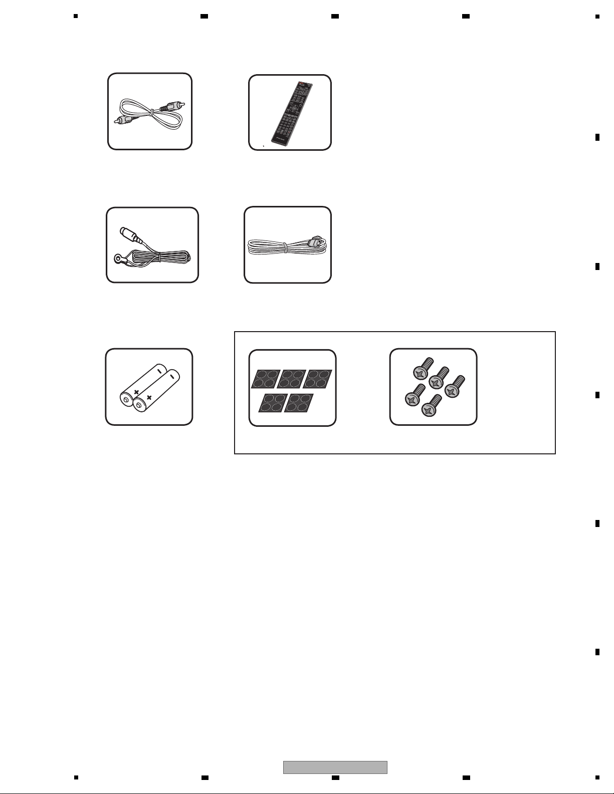
• Operating instructions
VIDEO cable
(41-UH1200-0KK1A)
Remote Control Unit
(06-AX7653-A000 : HTZ-121DVD/LXE, HTZ-121DVD/TWXE)
(06-AX7652-A000 : DCS-222K/YXE8)
AAA/R03 dry cell batteries x2
FM Antenna
(47-ANT022-XX0)
AC Power cord
(51-DC0120-0CRA3 : HTZ-121DVD/LXE, DCS-222K/YXE8)
(51-D50120-0CR03 : HTZ-121DVD/TWXE)
(HTZ-121DVD/LXE : 72-HTZ121-AS0B2)
(HTZ-121DVD/TWXE : 72-HTZ121-THAB1)
(DCS-222K/YXE8 : 72-DCS222-EU0B2)
• Warranty card (DCS-222K/YXE8)
Screws M4x12 [Taping type] x5
Non-skid pads x5
ACCESSORIES (SPEAKER ASSY)
2. SPECIFICATIONS
2.1 ACCESSORIES
6 7 8
A
B
C
D
5
HTZ-121DVD
6 7 8
E
F
5

1
General
• Power requirements:
AC 110 V to 240 V, 50 Hz/60 Hz (HTZ-121DVD/LXE)
AC 220 V, 50 Hz/60 Hz (HTZ-121DVD/TWXE)
AC 220 V to 240 V, 50 Hz/60 Hz (DCS-222K/YXE8)
• Power consumption: 45 W
In Standby mode: Less than 0.5 W
• Dimensions (W x H x D):
360 mm x 64 mm x 351 mm
• Net Weight (Approx.): 2.6 kg
• Operating temperature: 5 °C to 35 °C
• Operating humidity: 5 % to 85 %
• Bus Power supply (USB):
DC 5 V
500 mA
Inputs/Outputs
• VIDEO OUTPUT:
1.0 V (p -p), 75
sync negative, RCA jack x 1
• COMPONENT VIDEO OUT: (HTZ-121DVD)
(Y) 1.0 V (p-p), 75 sync negative, RCA jack x
1, (Pb)/(Pr) 0.7 V (p-p), 75 RCA jack x 2
• HDMI OUT (video/audio):
• SCART OUTPUT (video) : 21pin (DCS-222K)
19 pin (HDMI standard, Type A)
• PORTABLE IN:
0.5 Vrms (3.5 mm stereo jack)
• MIC INPUT: Mic jack
x
2
• USB: 4 pin A Type
Tuner
Amprifier
• FM Tuning Range:
87.5 MHz to 108.0 MHz
• Power output, (RMS), THD 30 %
Front 38 W x 2 (4
Centre 75 W (8
Surround 38 W x 2 (4
Sub-Woofer 75 W (8 Passive)
System
• Laser:Semiconductor laser
• Signal system:
Standard PAL/NTSC colour TV system
Speakers
• Front/Surround speaker (Left/Right)
Type: 1 Way
Impedance Rated:
4
Net Dimensions
(W x H x D):
95
mm x 80 mm x 90 mm
Net Weight: 0.33 kg
• Centre speaker
Type: 1 Way
Impedance Rated:
8
Net Dimensions
(W x H x D): 95 mm x 80 mm x 90 mm
Net Weight: 0.36 kg
• Subwoofer
Type: 1 Way
Impedance Rated:
8
Net Dimensions
(W x H x D):
200 mm x 340 mm x 270 mm
Net Weight: 3.4 kg
2.2 SPECIFICATIONS
A
B
2 3 4
C
D
E
F
6
1
HTZ-121DVD
2 3 4

5
DVD-Video
• DVD-Video discs
Playable Discs
• DVD-R/-RW/-R DL and
DVD+R/+RW/+R DL discs
recorded in the Video mode
DVD VR
DVD-R/-RW/-R DL discs
recorded in the VR mode
Video CD
Video CDs (including Super
VCDs)
CD(R/RW)
• Audio CDs
• CD-R/-RW/-ROM discs
containing music recorded in
the CD-DA format
JPEG
JPEG files recorded on
DVD-R/-RW/-R DL discs,
CD-R/-RW/-ROM discs
DivX
DivX video files recorded on
DVD-R/-RW/-R DL discs,
CD-R/-RW/-ROM discs
WMA
WMA files recorded on
DVD-R/-RW/-R DL discs,
CD-R/-RW/-ROM discs
MP3
MP3 files recorded on
DVD-R/-RW/-R DL discs,
CD-R/-RW/-ROM discs
can be played.
• This unit is not compatible to CPRM.
• Only the discs that have been finalized
Discs that cannot be played
• Blu-ray discs
• HD DVDs
• AVCHD
• AVCREC
• DVD-Audio discs
• DVD-RAM discs
• SACDs
• CD-G
• Discs recorded with packet writing
• Programs that can be recorded only
once and that are (already) recorded on
a DVD-R/-RW/-R DL
Regional Codes
This unit has a regional code printed on
the rear of the unit. This unit can play only
DVD discs labeled same as the rear of the
unit or “All”.
• Most DVD discs have a globe with one
or more numbers in it clearly visible on
the cover. This number must match your
unit’s regional code; or the disc cannot
play.
• If you try to paly a DVD with a defferent
regional code from your unit, the
message “Incompatible disc region
number Can’t play disc” appears on the
TV screen.
6 7 8
2.3 TYPES OF DISCS/FILES THAT CAN BE PLAYED
A
B
C
D
E
F
HTZ-121DVD
5
6 7 8
7
1
• Only discs recorded in ISO9660 Level1,
Level 2 and Joliet can be played.
• Files protected by DRM (Digital Rights
Management) cannot be played.
• Files other than the ones below (WMV,
MPEG4-AAC, etc.) are not guaranteed
to play.
DivX
Extension: .divx .avi
Resolution: up to 720 x 480
• DivX is a media technology created
by DivX, Inc. DivX media files contain
image data.
• DivX files may also include such
advanced playback functions as menu
screens and selection of multiple
subtitle languages/audio tracks.
• Files not
containing DivX video signals
cannot be played, even if they have the
extension “.avi”.
• The font sets listed below are available
for external subtitle files.
• This player supports the following
language groups:
Group 1 Afrikaans (af), Basque (eu), Catalan (ca),
Danish (da), Dutch (nl), English (en), Faroese
(fo), Finnish (fi), French (fr), German (de),
Icelandic (is), Irish (ga), Italian (it), Norwegian
(no), Portuguese (pt), Rhaeto-Romanic (rm),
Scottish (gd), Spanish (es), Swedish (sv)
Group 2 Albanian (sq), Croatian (hr), Czech (cs),
Hungarian (hu), Polish (pl), Romanian (ro),
Slovak (sk), Slovenian (sl)
Group 3 Bulgarian (bg), Byelorussian (be), Macedonian
(mk),Russian (ru), Serbian (sr), Ukrainian (uk)
Group 4 Hebrew (iw), Yiddish (ji)
Group 5 Turkish (tr)
• Some external subtitle files may be
displayed incorrectly or not at all.
• For external subtitle files the following
subtitle format filename extensions are
supported (please note that these files
are not shown within the disc navigation
menu): .srt, .sub, .ssa, .smi
• The filename of the movie file has to
be repeated at the beginning of the
filename for the external subtitle file.
• The number of external subtitle files
which can be switched for the same
movie file is limited to a maximum of 10.
Playable files
Supported video file formats
Displaying external subtitle files
A
2 3 4
B
C
D
E
F
8
1
2 3 4
HTZ-121DVD

5
JPEG
Extension: .jpg .jpeg
• Resolution: Up to 3 072 x 2 048 pixels
• This player supports baseline JPEG.
• This player supports Exif Ver.2.2.
• This player does not support VBR
(Variable Bit Rate) and lossless
encoding.
Windows Media™ Audio (WMA)
Extension: .wma
• Sampling frequencies: 32 kHz, 44.1 kHz
and 48 kHz
• Bit rate: Up to 192 kbps
• This player supports files encoded
using Windows Media Player Ver. 7/7.1,
Windows Media Player for Windows XP
and
Windows Media Player 9 Series.
• Windows Media is either a registered
trademark or trademark of Microsoft
Corporation in the United States and/or
other countries.
• This product includes technology owned
by Microsoft Corporation and cannot
be used or distributed without a license
from Microsoft Licensing, Inc.
MPEG-1 Audio Layer 3 (MP3)
Extension: .mp3
• Sampling
frequencies: 32 kHz, 44.1 kHz
and 48 kHz
• Bit-rates: 128 kbps or higher
recommended
• This Player supports ID3 tag Ver1.1.
Compatible USB Devices
• MP3 Player : Flash type MP3 player.
• USB Flash Drive : Devices that support
USB 2.0 or USB 1.1.
• The USB function of this unit does not
support some USB devices.
USB device requirement
• Devices which require additional
program installation connected to a
computer, are not supported.
• Do not extract the USB device while in
operation.
• For a large capacity USB, it may
take longer than a few minute to be
searched.
• To prevent data loss, back up all data.
• If you use a USB extension cable or USB
hub, the USB device is not recognized.
• Using
NTFS file system is not
supported. (Only FAT(16/32) file system
is supported.)
• This unit is not supported when the total
number of files is 600 or more.
• External HDD, Card readers, Locked
devices, or hard type USB devices are
not guaranteed to support.
• USB port of the unit cannot be
connected to PC. The unit can not be
used as a storage device.
• Some copyright-protected files cannot
be played.
• The
maximum d
isplayable number of
characters for the folder and file names
on the Disc Navigator is 14.
• The order of the folder and file names
displayed on the Disc Navigator is
dependant on the time and date when
the folders or files were created on the
USB device.
Supported image file formats
Supported audio file formats
6 7 8
A
B
C
D
E
F
HTZ-121DVD
5
6 7 8
9
1
HDMI, the HDMI Logo, and High-Definition
Multimedia Interface are trademarks or
registered trademarks of HDMI Licensing LLC
in the United States and other countries.
is a trademark of DVD Format/Logo
Licensing Corporation.
Manufactured under license from Dolby
Laboratories. “Dolby”, “Pro Logic”, and the
double-D symbol are trademarks of Dolby
Laboratories.
DivX®, DivX Certified® and associated logos
are trademarks of Rovi Corporation or its
subsidiaries and are used under license.
This product includes technology owned by
Microsoft Corporation and cannot be used or
distributed without a license from Microsoft
Licensing, Inc.
Trademarks and Licences
A
B
2 3 4
C
D
E
F
10
1
2 3 4
HTZ-121DVD
5
Item to be checked regarding video Item to be checked regarding audio
Block noise Distortion
Horizontal noise Noise
Dot noise Volume too low
Disturbed image (video jumpiness) Volume too high
Too dark Volume fluctuating
Too bright Sound interrupted
Color disappearance
Mottled color
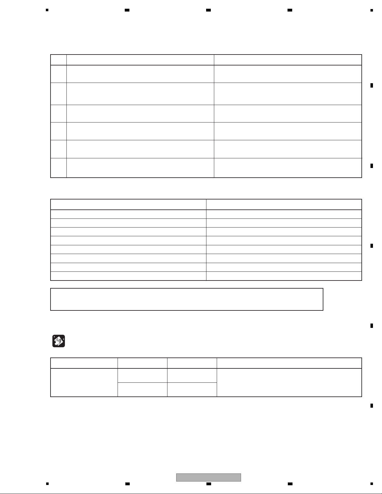
No. Procedures Check points
1
2
3
4
6
5
Confirm the firmware version on Test Mode. The version of the firmware must be latest.
Update firmware to the latest one, if it is not the latest.
Confirm whether the customer complain has been solved.
If the customer complain occurs with the specific disc, use it for
the operation check.
The customer complain must not be reappeared.
Video, audio and operations must be normal.
Play back a CD.
(track search)
Audio and operations must be normal.
Play back a DVD.
(Menu operation, Title/chapter search)
Video, audio and operations must be normal.
Check the appearance of the product. No scratches or dirt on its appearance after receiving it for
service.
Check the tuner (FM) operations. Audio and operations (station search etc.) must be normal.
To keep the product quality after servicing, confirm recommended check points shown below.
See the table below for the items to be checked regarding video and audio.
Cleaning
Be sure to clean the following positions by using the prescribed cleaning tools shown below as occasion demands.
Refer to “7. DISASSEMBLY”.
NamePosition to be cleaned Part No. Remarks
Cleaning liquidPickup leneses GEM1004
Cleaning paper GED-008
Note
If checking audio output of the unit without an original speaker, please order GGP1199 (Speaker cable jig).
It is possible to connect a normal speaker to the unit by using GGP1199.
6 7 8
3. BASIC ITEMS FOR SERVICE
3.1 CHECK POINTS AFTER SERVICING
A
B
C
D
5
HTZ-121DVD
6 7 8
E
F
11
1
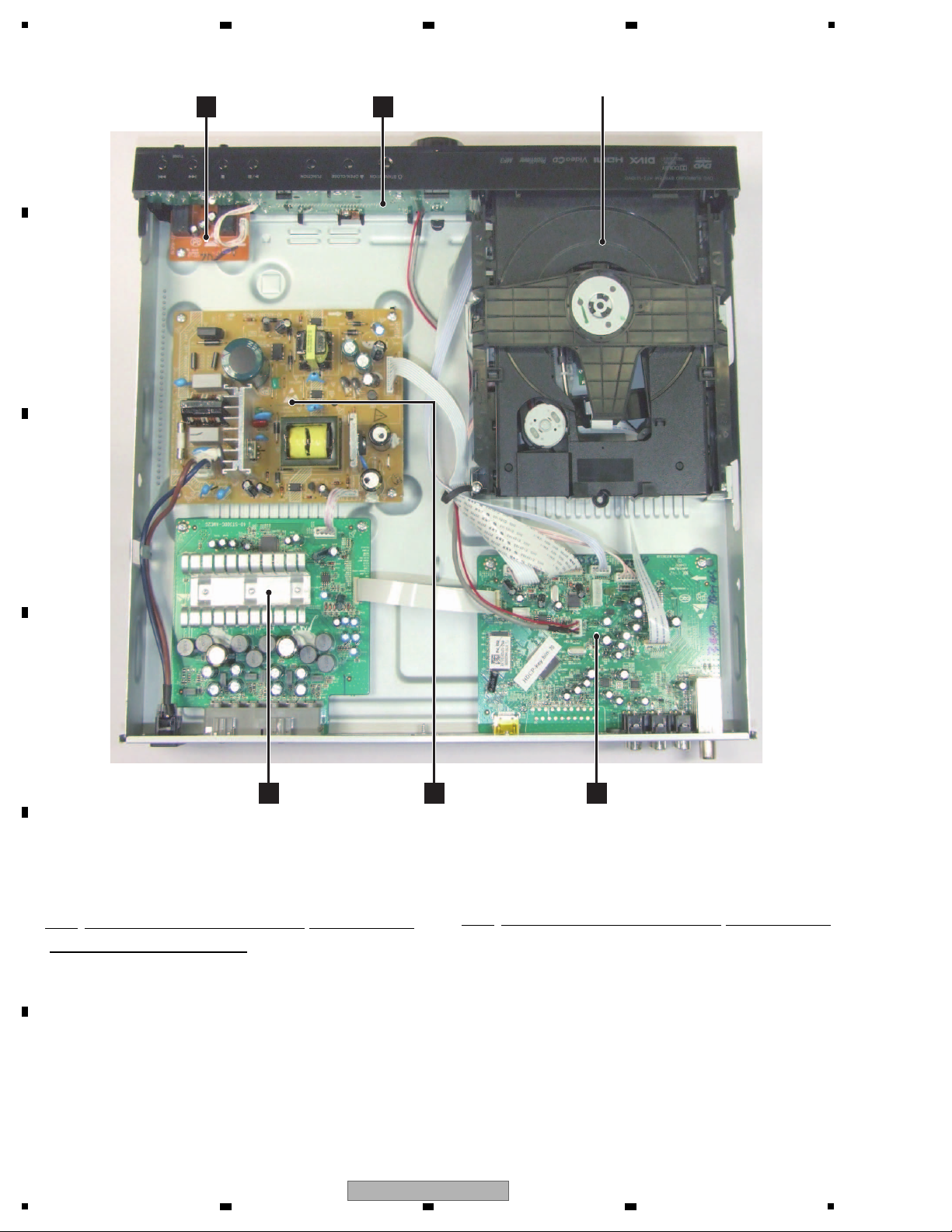
NOTES: - Parts marked by “NSP” are generally unavailable because they are not in our Master Spare Parts List.
-
The > mark found on some component parts indicates the importance of the safety factor of the part.
Therefore, when replacing, be sure to use parts of identical designation.
POWER BOARD ASSY
FRONT BOARD ASSYKARAOKE BOARD ASSY
MAIN BOARD ASSY
A
AMP BOARD ASSY
D E
B
Loader ASSY
C
3.2 PCB LOCATIONS
A
B
2 3 4
C
D
E
Mark No. Description Part No.
LIST OF ASSEMBLIES
1..MAIN BOARD ASSY (HTZ-121DVD/LXE) 08-HTZ121-MA0
1..MAIN BOARD ASSY (HTZ-121DVD/TWXE) 08-H89GAU-MA1R
1..MAIN BOARD ASSY (DCS-222K/YXE8) 08-DCS222-MA0
1..FRONT BOARD ASSY 08-DCS222-FB0
1..KARAOKE BOARD ASSY 08-DCS222-KU0
1..AMP BOARD ASSY 08-DCS222-AM0
F
12
(HTZ-121DVD/LXE, DCS-222K/YXE8)
1..AMP BOARD ASSY(HTZ-121DVD/TWXE) 08-S301B6-AM1
1
HTZ-121DVD
2 3 4
Mark No. Description Part No.
> 1..POWER BOARD ASSY 08-DCS222-PW0
(HTZ-121DVD/LXE, DCS-222K/YXE8)
> 1..POWER BOARD ASSY (HTZ-121DVD/TWXE) 08-P075HE-PW1
1..Loader ASSY 08-LT3CMP-242230

5
DVD Test Disc (DVD-Video,NTSC)
DVD Test Disc (DVD-Video,PAL)
Name Jig No. Remarks
Diagnosis
Diagnosis
GGV1025
DVD Test Disc (DVD-Video,NTSC) Diagnosis
GGV1025
Service Remote Control Unit Service Mode
GGF1381
GGV1101
CD Test Disc
Diagnosis
STD-905
Speaker cable for AMP output check
AMP Check
GGP1199
3.3 JIGS LIST
6 7 8
A
B
C
D
E
HTZ-121DVD
5
6 7 8
F
13

1
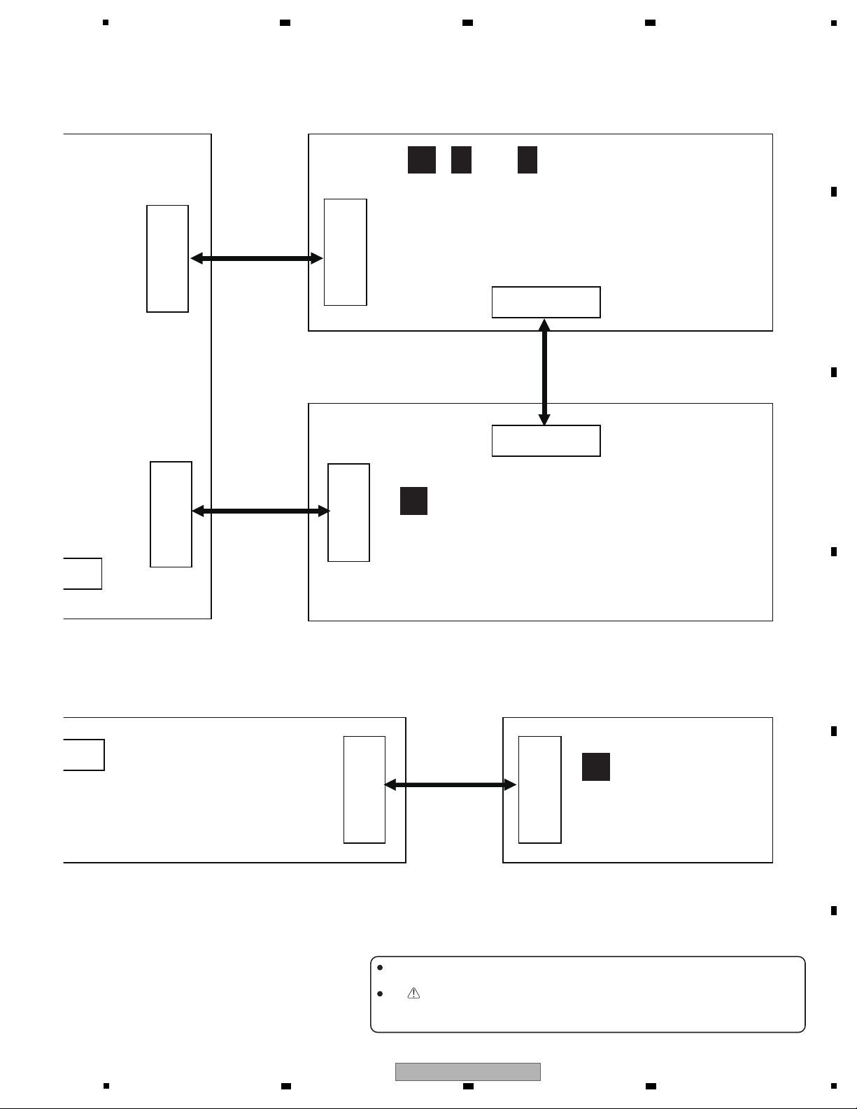
XP3
XP12
XP4
XP2
XP3
PICK UP
TRAVERS
TRAY
6PIN
HARNESS
CABLE
24PIN FFC
CABLE
24PIN FFC
CABLE
5PIN
HARNESS
CABLE
XP5
XS604
4PIN
HARNESS
CABLE
USB
FRONT BOARD ASSY (08-
B
A
A
1/6 -A6/6
( )
MAIN BOARD ASSY
(HTZ-121DVD/LXE : 08-HTZ121-MA0)
(HTZ-121DVD/TWXE : 08-H89GAU-MA1R)
(DCS-222K/YXE8 : 08-DCS222-MA0)
LOADER ASSY
2 3 4
4. BLOCK DIAGRAM
4.1 OVERALL CONNECTION DIAGRAM
A
B
C
D
E
F
14
HTZ-121DVD
1
2 3 4
5
XP502
XP11
XP1
XP501
XP701
XS606
XS1
XS703
8PIN
HARNESS
CABLE
24PIN FFC
CABLE
4PIN
HARNESS
CABLE
3PIN
HARNESS
CABLE
When ordering service parts, be sure to refer to "EXPLODED VIEWS and PARTS
LIST" or "PCB PARTS LIST".
The mark found on some component parts indicates the importance of the safety
factor of the part. Therefore, when replacing, be sure to use parts of identical
designation.
POWER BOARD ASSY
(HTZ-121DVD/LXE,
DCS-222K/YXE8 : 08-DCS222-PW0)
(HTZ-121DVD/TWXE : 08-P075HE-PW1)
E
ASSY (08-DCS222-FB0)
KARAOKE
BOARD ASSY
(08-DCS222-KU0)
C
D
D
1/2 -D2/2
( )
AMP BOARD ASSY
(HTZ-121DVD/LXE,
DCS-222K/YXE8 : 08-DCS222-AM0)
(HTZ-121DVD/TWXE : 08-S301B6-AM1)
6 7 8
A
B
C
D
E
F
5
6 7 8
HTZ-121DVD
15

1
FRONT BOARD ASSY
B
KARAOKE
BOARD ASSY
C
A
MAIN BOARD ASSY
4.2 BLOCK DIAGRAM
A
B
2 3 4
C
D
E
F
16
1
2 3 4
HTZ-121DVD

5
(HTZ-121DVD)
(DCS-222K)
POWER BOARD ASSY
E
D
AMP BOARD ASSY
6 7 8
A
B
C
D
E
5
HTZ-121DVD
6 7 8
F
17
1
No
No
Yes
Yes
No display on VFD, and
buttons do not work
Check every supply
voltage on MAIN BOARD ASSY
is normal
Check the connect line is OK
Correct connection
Replace K135, K136,
K137,K138,K139,K140
Go
No
No
Check the FRONT BOARD
ASSY signals VSCLK,VSDA,VSTB
(XP3:pin10,pin11,pin12)
Check whether the circuit
connected to K135,K136,K137,
K138,K139,K140 are broken.
Check Q2,Q3,Q4 is
fixed on MAIN BOARD ASSY
Yes
Replace MAIN BOARD ASSY
2 3 4
5. DIAGNOSIS
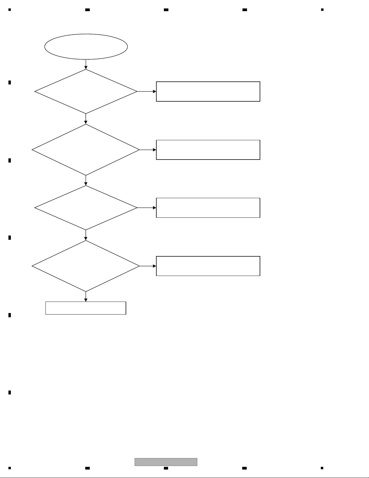
5.1 DIAGNOSIS FLOWCHART
1) No display on VFD, and buttons do not work
A
B
C
D
E
F
18
1
2 3 4
HTZ-121DVD

5
Go
Yes
No
Yes
Remote control
does not work
No
Replace the battery for remote
controller
Check whether the remote
controller’s battery is
exhausted or not
Check the IR601(HT68F50)
power supply is OK,
IR601 : pin3 is about 3.3V
Check the VCC line(net) on FRONT BOARD ASSY
Replace FRONT BOARD ASSY
2) Remote control does not work
6 7 8
A
B
C
D
E
F
HTZ-121DVD
5
6 7 8
19
1
No audio output
Go
No
Yes
Yes
Yes
Replace AMP BOARD ASSY
No
Replace U182 on MAIN BOARD ASSY,
or replace MAIN BOARD ASSY
Yes
Refer to CN502 on
POWER BOARD ASSY
Check the voltage +33V
Check the 24pin FFC connection
XP11 on MAIN BOARD ASSY and XP701
on AMP BOARD ASSY whether right or not
between MAIN BOARD ASSY
and AMP BOARD ASSY
Check the control signal at U182 :
pin10 and pin11 on MAIN BOARD ASSY
and the signal at XP11 : pin9 and
pin10 whether right or not
Check the voltage 3.3V at XP11 :
pin14 and pin16 on MAIN BOARD ASSY
whether normal or not
No
whether normal or not
at XS703 on AMP BOARD ASSY
3) No audio output
A
2 3 4
B
C
D
E
F
20
1
HTZ-121DVD
2 3 4
5
No video output
Go
Replace L7 on MAIN BOARD ASSY
Yes
No
No
Replace MAIN BOARD ASSY
Check L7 on MAIN BOARD ASSY
whether right
Check the video signal
at U20 : pin98 on MAIN BOARD
ASSY whether right
Can’t read disc or can’t
open the disc door
Check XP3 on MAIN BOARD ASSY
Fix XP2(24pin), XP4(6pin)
and XP3(5pin) cable
Replace Loader
Check the loader whether
work normally or not
Check the
XP2(24pin), XP4(6pin) and
XP3(5pin) cable from MAIN BOARD
ASSY to Loader whether
connect right or not
Go
Yes
No
Yes
No
4) No video output
6 7 8
A
B
5) Can’t read disc or can’t open the disc door
C
D
E
5
HTZ-121DVD
6 7 8
F
21
1
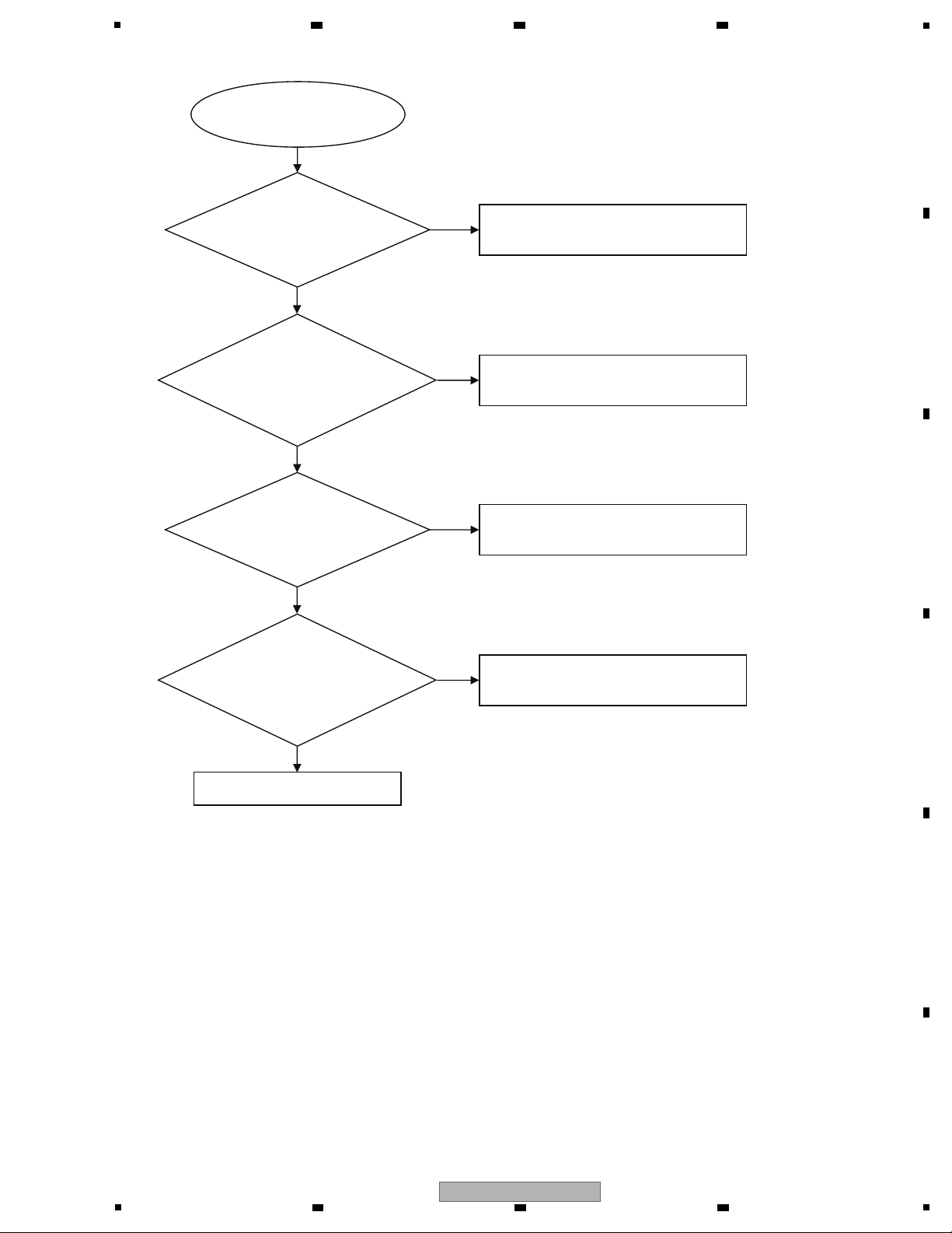
Tuner FM does not work
Refer to CN502 on POWER BOARD ASSY
Check the tuner power supply circuit
on MAIN BOARD ASSY
Change Tuner Module
Replace MAIN BOARD ASSY
Check the U182 power supply circuit
on MAIN BOARD ASSY
Check the voltage +3.3V
at Tuner Module (TUN1 : pin5)
whether right or not
Check the Tuner Module
(pin3,pin4 : I2C intput) whether
normal or not
Check the
voltage at Q16 : +3.3V on
MAIN BOARD ASSY whether
normal or not
Check the U182 (pin35,
pin36 : I2C output) on MAIN BOARD
ASSY whether normal or not
Go
Yes
No
Yes
No
Yes
No
Yes
No
6) Tuner FM does not work
A
B
2 3 4
C
D
E
F
22
1
2 3 4
HTZ-121DVD

5
AUX in does not work
Check R436 and C270
Replace MAIN BOARD ASSY
Check the U33(74HC4052) whether
broken or not
Check the voltage at
U33(74HC4052) : pin16(MO_VCC)
on MAIN BOARD ASSY whether
normal or not
Check the R341,R342,
C160 and C162 on MAIN BOARD ASSY
whether normal or not
Go
Yes
No
Yes Yes
No
Replace MAIN BOARD ASSY
7) AUX in does not work
6 7 8
A
B
C
D
E
F
HTZ-121DVD
5
6 7 8
23
1
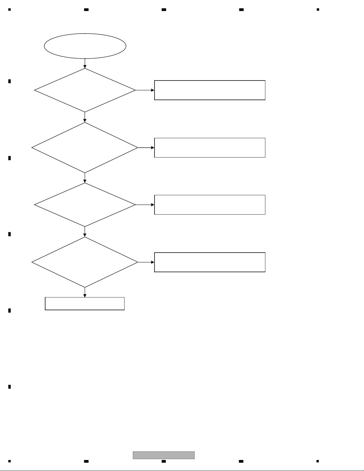
Portable IN does not work
Refer to XP12 on MAIN BOARD ASSY
Check R457,R340,C169 and C170
on MAIN BOARD ASSY
Replace MAIN BOARD ASSY
Check U20 on MAIN BOARD ASSY
Check the Q4 power supply and out
circuit on MAIN BOARD ASSY
Check the signal
at JACK602 : pin3(MP3_R),
pin2(MP3_L) on FRONT BOARD
ASSY whether normal
or not
Check the U33
(74HC4052) : pin4, pin11 (L/R
signal input) on MAIN BOARD ASSY
whether right or not
Check the U33(74HC4052)
whether broken or not
Check the voltage at
U33(74HC4052) : pin16(MO_VCC)
on MAIN BOARD ASSY whether
normal or not
Go
Yes
No
Yes
No
Yes
No
Yes
No
8) Portable IN does not work
A
B
C
2 3 4
D
E
F
24
1
2 3 4
HTZ-121DVD
5
Refer to XP12 on MAIN BOARD ASSY
Check R458,R459,C168 and C176
on MAIN BOARD ASSY
Replace MAIN BOARD ASSY
Check U20 on MAIN BOARD ASSY
Check the Q4 power supply and out
circuit on MAIN BOARD ASSY
Check the signal
at P462 and P461 : pin1 on
KARAOKE BOARD ASSY
whether normal
or not
Check the U33(74HC4052)
: pin2, pin15 (L/R signal input) on
MAIN BOARD ASSY whether
right or not
Check the U33(74HC4052) whether
broken or not
Check the voltage at
U33(74HC4052) : pin16(MO_VCC)
on MAIN BOARD ASSY whether
normal or not
KARAOKE IN does not work
Go
Yes
No
Yes
No
Yes
No
Yes
No
9) KARAOKE IN does not work
6 7 8
A
B
C
D
E
F
HTZ-121DVD
5
6 7 8
25

1
HDMI does not output
Replace P3
Replace MAIN BOARD ASSY
Check the signal at P3 on MAIN
BOARD ASSY whether
normal or not
Check the voltage at P3 : pin18
(HDMI_VCC) whether right or not
Replace FB15
Go
Yes
Yes
No
No
10) HDMI does not output
A
2 3 4
B
C
D
E
F
26
1
2 3 4
HTZ-121DVD

5
Only during normal playback, the following shortcut keys can be assigned by pressing a required key after pressing the ESC
key of the remote control unit. To quit, press the ESC key
Command Contents Condition Remote Control Key Name
Calculation of the average error rate 5(*1)
(DVD and CD)
Progressive OFF Only for progressive model PREV
Progressive ON NEXT
Display during Service Mode CHP/TIM(*1)
(error rate indication,etc )
Model information indication CHAP(*1)
*1 : Service remote control unit
• Calculation of the average error rate
To calculate of the average error rate, press the 5 key while holding the ESC key pressed.
To quit, press the ESC key.
The average of the last eight error rates is calculated and indicated in exponential notation.
After the calculation is completed, if the resulet is OK, "OK" is displayed on screen.
If the result is NG, the disc tray will open automatically (for both DVDs and CDs).
For DVDs: OK with 5.0e-4 or less, for CDs: OK with 7.6e-3 or less
•
Display during Service Mode
To enter Service Mode, press the CHP/TIM key while holding the ESC key pressed.
To quit, press the ESC key.
Service Mode display
1 ID Address
2 Error rate (always displayed), in exponential notation
ERROR RATE : ∗ ∗ ∗ ∗ ∗ ∗ ∗
( ∗ ∗ ∗ ∗ )
•
Calculation of the average error rate
For DVDs: OK with 5.0e-4 or less, for CDs: OK with 7.6e-3 or less
3 EDC/ID error history (ID Address, EDC/ID errors, last eight errors)
Note:
∗ Error of AV1 is not supported in this player.
Number of error
Indication plan contents
Character in bold : Item name
: Inform ation display
1
2
3
ex) For DVDs
•
Step 1
e-
e -6 : OK
e -5 : OK
e -4 : Refer to Step 2
e -3 : NG
e -2 : NG
•
Step 2
e -4
3.0e -4 : OK
4.0e -4 : OK
5.0e -4 : OK
6.0e -4 : NG
7.0e -4 : NG
6 7 8
6. SERVICE MODE
A
B
C
D
E
F
HTZ-121DVD
5
6 7 8
27

1
• Indication of model information (ESC + CHAP keys)
To display model information, press the CHAP key while holding the ESC key pressed.
To quit, press the ESC key.
MODEL NAME: HTZ-121DVD/LXE
MPEG_VERSION : V**
MCU_NAME: MCU_300_OTHER_V**
REGION: **
1 :
MODEL NAME
2 :
MPEG Software Version
3 :
MCU Software Name and Version
(*) : MCU Software is different by model.
After upgrading MCU Software, please confirm MODEL_NAME and MCU_NAME
by necessity.
4 :
DVD REGION NUMBER
3
2
1
4
A
2 3 4
B
C
D
E
F
28
1
2 3 4
HTZ-121DVD

5
Slit
• Bottom view
Lever
To p Cov e r
Screwdriver
(small)
Note 1 : Do NOT look directly into the pickup lens. The laser beam may cause eye injury.
Note 2 : Even if the unit shown in the photos and illustrations in this manual may differ from your product, the procedures
described here are common.
1
1
1
1
1
2
2
XP12
XP5
MAIN BOARD ASSY
While
spreading
While
spreading
2
1
2
2
[1] Top Cover
(1) Remove the five screws.
(63-B30060-3H3)
(2) Remove upward the Top Cover while
spreading the rear side of Top Cover.
• How to open the Tray when the power
cannot be turned on
If the Tray is not opened and the disc cannot be
pulled out by operating OPEN/CLOSE
button, open the Tray forcibly in the method
shown below.
Insert a Screwdriver (small) into the Slit located
at the bottom of the unit, and slide the Lever in
the direction of the arrow, as indicated in the
photo.
If the Tray is unlocked, slide it out by hand.
[2] Front Cabinet Section
(1) Release the jumper wires from the Binder.
(2) Disconnect the two connectors (XP5, XP12)
from the MAIN BOARD ASSY.
6 7 8
7. DISASSEMBLY
A
B
C
D
5
HTZ-121DVD
6 7 8
E
F
29

1
1
1
2 2
MAIN BOARD ASSY
3 3
3
4
KARAOKE BOARD ASSY
• Bottom view
Front Panel ASSY
VOL Knob ASSY
Cloth
VOL Knob ASSY
Cloth
x 4
[ Case of HTZ-121DVD ]
[ Case of DCS-222K ]
1
1
2
22
-1
5
-2
5
(3) Remove the screw. (63-B30070-3H4)
(4) Unhook the four hooks of the Front Panel
ASSY and remove the Front Cabinet Section.
(5) Remove the VOL Knob ASSY.
Note: The VOL Knob ASSY is difficult to remove.
Wrap a piece of Cloth around the Knob for
better grip, fitting one edge of the Cloth
into the gap behind the Knob, then pull it
straight out.
[3] MAIN BOARD ASSY and
AMP BOARD ASSY
(1) Remove the two screws on the rear side.
(64-B30040-304)
(2) Remove the screws on the rear side.
[ HTZ-121DVD: two screws ]
[ DCS-222K: three screws ]
(63-B30070-3H4)
(3) Remove the two screws (63-B30070-3H4) of
the MAIN BOARD ASSY.
A
B
2 3 4
C
D
E
F
30
1
HTZ-121DVD
2 3 4

5
AMP BOARD ASSY
4 4
5 5
XP12
FRONT BOARD ASSY
Bottom Plate
XP5
MAIN BOARD ASSY
1
1
Insulation Sheet
MAIN BOARD ASSY
AMP BOARD ASSY
4
3
3
2
(4) Remove the two screws on the rear side.
(63-B30070-3H4)
(5) Remove the two screws (63-B30070-3H4) of
the AMP BOARD ASSY.
[4] Diagnosis
(1) Connect the two cables of the FRONT
BOARD ASSY to the MAIN BOARD ASSY.
(2) Connect the FRONT BOARD ASSY to the
ground of the Bottom Plate.
(3) Reverse MAIN BOARD ASSY and AMP
BOARD ASSY and allocate each unit as
shown in the photo.
(4) Insert the insulation sheet.
6 7 8
A
B
C
D
E
HTZ-121DVD
5
6 7 8
F
31

1
Caution 1:
When you attach each unit, make a styling and
connection of cables as shown in the photo.
Caution 2:
Nothing should be connected to the connector
part surrounded by red line.
Styling of cables between units
A
B
2 3 4
C
D
E
F
32
1
2 3 4
HTZ-121DVD

5
Front
Front
XP3
XP2
MAIN BOARD ASSY
2
2
1
4
4
5
5
XP4
Loader ASSY
(bottom side)
Loader ASSY
Hook
Hook
FFC Holder
Binder
3
x 3
Chassis Traverse
(1) Disconnect the three connectors (XP2, XP3,
XP4) from the MAIN BOARD ASSY.
(2) Remove the two screws and then remove the
Loader ASSY and the Binder.
(63-B30070-3H4)
(3) Remove the FFC Holder by removing the
hooks at left and right hand side of the FFC
Holder located at bottom side of the Loader
ASSY.
(4) Remove the two screws.
(5) Remove the two screws and then remove the
Chassis Traverse.
Cleaning the Pickup Lenses
6 7 8
A
B
C
D
5
HTZ-121DVD
6 7 8
E
F
33

1
pick-up portion
Chassis Traverse
Pickup Lenses
(6) Clean the pickup lenses when it is stained,
using following cleaning materials:
Cleaning liquid : GEM1004
Cleaning paper : GED-008
Caution:
The pickup is a high-precision component;
therefore, clean the lens with enough care so
as not to cause a misalignment in the optical
axis.
A
B
2 3 4
C
D
E
F
34
1
2 3 4
HTZ-121DVD

5
Front
Loader ASSY
2
3
pick-up portion
protection point
Replace the Loader ASSY
(1) Replace the Loader ASSY.
(Refer to the step (1) to (2) of “Cleaning
the Pickup Lenses.” )
(2) Shift the Pick-Up Portion backward.
(3) Please remove solder at protection point to
the arrow-mark direction by using soldering
iron with your right-hand while holding the
pick-up portion with your left-hand after the
completion of all mounting.
(Photo shows the situation after the removal
of solder)
6 7 8
A
B
C
D
E
F
HTZ-121DVD
5
6 7 8
35

1
Method of Software Upgrading:
Software includes 2 parts: MPEG Software and MCU Software.
Both of them can upgrade by USB.
Notice:
The system can't upgrade both MPEG Software and MCU Software at same time.
Method of MPEG Software Upgrading:
1. Change the name of MPEG Software file into "DCS-222K.BIN",
then put it in the root path of USB .
Notice: DCS-222K.BIN must be big letters.
(For example, if file name is "DCS-222K.bin",the system can't recognize it.)
Don't put MPEG Software file and MCU Software file at the same time,
otherwise the system upgrade only MCU Software.
2. Please insert USB into the system and turn power-on.
3. Select USB function by pressing USB key or pressing FUNCTION key on Remote Control Unit.
The system will search the upgrade file itself at this time, a dialog for upgrade is displayed on screen.
Then by pressing PLAY key on Remote Control Unit, "UPG - MPEG" is displayed on FL tube and the upgrade starts.
It takes about 5 minutes by finishing upgrade.
Notice:
Please don't interruption the power supply and extraction USB during upgrading.
4. After upgrading successful, the system will restart.
Then if the system displays a dialog for upgrade again, please extract without pressing PLAY key.
Method of MCU Software Upgrading:
1. Change the name of MCU Software file into "MCU.BIN",
then put it in the root path of USB .
Notice: MCU.BIN must be big letters.
2. Please insert USB into the system and turn power-on.
3. Select USB function by pressing USB key or pressing FUNCTION key on Remote Control Unit.
The system will search the upgrade file itself at this time, a dialog for upgrade is displayed on screen.
Then by pressing PLAY key on Remote Control Unit, "UPG - MCU" is displayed on FL tube and the upgrade starts.
It takes about 5 minutes by finishing upgrade.
Notice:
Please don't interruption the power supply and extraction USB during upgrading.
4. After upgrading successful, the system will standby.
2 3 4
8. EACH SETTING AND ADJUSTMENT
8.1 FIRMWARE UPDATE
A
B
C
D
E
F
36
1
2 3 4
HTZ-121DVD

5
(*) MCU Software is different by model.
After upgrading MCU Software, please confirm MODEL_NAME and MCU NAME. by necessity.
You can confirm model information by pressing ESC + CHAP keys on Service Remote
Control Unit.
If you upgraded incorrect MCU software, please upgrade correct MCU software again.
Model Name MCU NAME
DCS-222K/YXE8 MCU_300_EU_V**
HTZ-121DVD/LXE MCU_300_OTHER_V**
HTZ-121DVD/TWXE
HTZ-121DVD/AXQ5
HTZ-120DVD/DXERB
HTZ-121DVD/DXECS
HTZ-222DVD/LXE MCU_600_OTHER_V**
HTZ-222DVD/TWXE
HTZ-222DVD/AXQ5
HTZ-222DVD/DXERB
HTZ-221DVD/DXECS
DCS-424K/YXE8 MCU_1000_EU_V**
DCS-424K/SXE5 MCU_1000_OTHER_V**
HTZ-424DVD/LXE
HTZ-424DVD/TWXE
HTZ-424DVD/DXERB
HTZ-424DVD/AXQ5
HTZ-421DVD/DXECS
** is version number
6 7 8
A
B
C
D
E
F
HTZ-121DVD
5
6 7 8
37

1
1. Upgrading the MPEG Software for Service
• Upgrade the MPEG Software for service of the product.
Change the following file into "DCS-222K.BIN" and put it in the root path of USB.
DCS-222K series
• DCS-222K_SP.BIN
Please refer to "Method of MPEG Software Upgrading" of Software upgrade about the procedure of upgrading the
MPEG Software.
Notice: The system has MPEG Software and MCU Software.
But the software for service is only MPEG Software.
2. Changing the Destination Setting
1 At the Pioneer Logo screen, press OPEN/CLOSE button.
2 With Tray open, press AUDIO button and press the numeric buttons 1, 2, 3, then 4, in that order,
on the supplied Remote Control Unit.
Then the Destination Setting screen is displayed on screen.
Page1:
Page2:
Page3:
2 3 4
8.2 PROCEDURES FOR CHANGING THE DESTINATION SETTING AFTER THE MAIN BOARD IS REPLACED
A
B
C
D
E
F
38
1
2 3 4
HTZ-121DVD

5
3 Select your region by moving the UP button or the DOWN button, and press the ENTER button on the supplied
Remote Control Unit.
Then the system turns power off automatically.
Note:DVD Region is set automatically according to the selected destination.
4 Power on and load default settings.
Press Home Menu button on the supplied Remote Control Unit and select Initial Settings after power on.
Then select options and load default.
When Yes is selected at Load default confirm screen, the system loads default settings according to the destination.
3. Confirming the Destination Change
Check if the Destination Setting has been properly changed.
Press ESC button , then press CHAP button on the Service Remote Control Unit.
On the Model Information screen, if the destination that was selected on step 3 in
“2. Changing the Destination Setting” is displayed for the “MODEL NAME” item,
destination change has been successfully finished.
Please refer to "Indication of model information" of Service Mode about Model Information screen.
4. Upgrading the Latest Software to the Product
1 Upgrade the latest Software for the product from the Website specially for service engineers to a USB storage
device.
2 Perform updating in the same manner as that described in "Software Upgrade".
Notice: You must upgrade both MPEG Software and MCU Software.
Be sure to write the latest Software that suits the destination of the product,
because the product will not operate properly with the Software for service,
which is used for changing the Destination Setting.
6 7 8
A
B
C
D
E
F
HTZ-121DVD
5
6 7 8
39

1
NOTES: - Parts marked by “NSP” are generally unavailable because they are not in our Master Spare Parts List.
-
The > mark found on some component parts indicates the importance of the safety factor of the part.
Therefore, when replacing, be sure to use parts of identical designation.
-
Screws adjacent to b mark on product are used for disassembly.
-
For the applying amount of lubricants or glue, follow the instructions in this manual.
(In the case of no amount instructions, apply as you think it appropriate.)
HTZ-121DVD/LXE,
DCS-222K/YXE8
only
HTZ-121DVD/TWXE
only
DCS-222K
/YXE8 only
2 3 4
9. EXPLODED VIEWS AND PARTS LIST
A
9.1 PACKING SECTION
B
C
D
E
F
40
1
2 3 4
HTZ-121DVD

5
6 7 8
(1) PACKING SECTION PARTS LIST
Mark No. Description Part No.
> 1 AC Power Cord See Contrast table (2)
2 Remote Control Unit See Contrast table (2)
3 Video Cable
4 FM Antenna 47-ANT022-XX0
5 • • • • •
41-UH1200-0KK1A
Mark
No. Description Part No.
11 • • • • •
12 Pad Left 75-DC22L1-EA0
13 Pad Right 75-DC22R1-EA0
14 Packing Case See Contrast table (2)
15 SPEAKER ASSY CENTER SMX1124-C
A
6 • • • • •
7 Polyethylene Bag
8 Operating Instructions See Contrast table (2)
9 • • • • •
10 Polyethylene Bag
74-018025-51C
74-050047-60GB1
16 SPEAKER ASSY FRONT L SMX1124-F-L
17 SPEAKER ASSY FRONT R SMX1124-F-R
18 SPEAKER ASSY SURROUND SMX1124-S-L
19 SPEAKER ASSY SURROUND SMX1124-S-R
20 Polyethylene Bag 3880V-S004A
21 Packing Top Bottom 3920V-0019A
SPEAKER ASSY SUB-WOOFER
22
23 Soft Bag MAF62208304
24 Packing Top Bottom 3920V-0002A
SMX1128-W
(2) CONTRAST TABLE
HTZ-121DVD/LXE, HTZ-121DVD/TWXE and DCS-222K/YXE8 are constructed the same except for the following:
Mark No. Symbol and Description
1 AC Power Cord 51-DC0120-0CRA3 51-D50120-0CR03 51-DC0120-0CRA3
>
2 Remote Control Unit 06-AX7653-A000 06-AX7653-A000 06-AX7652-A000
8 Operating Instructions 72-HTZ121-AS0B2 72-HTZ121-THAB1 72-DCS222-EU0B2
14 Packing Case 76-111710-0ATB2 76-111710-0ATB3 76-111710-0ATB1
HTZ-121DVD/
LXE
HTZ-121DVD/
TWXE
DCS-222K/
YXE8
B
C
D
E
F
HTZ-121DVD
5
6 7 8
41

1
CONTACT SIDE
NON-CONTACT
SIDE
HTZ-121DVD/LXE,
HTZ-121DVD/TWXE
only
DCS-222K/YXE8 only
A
A
A
A
B
B
C
C
D
D
E
E
G
H
H
G
E
D
A
C
B
F
F
9.2 EXTERIOR SECTION
A
2 3 4
B
C
D
E
F
42
1
2 3 4
HTZ-121DVD

5
6 7 8
(1) EXTERIOR SECTION PARTS LIST
Mark No. Description Part No.
1 FRONT BOARD ASSY 08-DCS222-FB0
2 MAIN BOARD ASSY See Contrast table (2)
> 3 POWER BOARD ASSY See Contrast table (2)
4 KARAOKE BOARD ASSY 08-DCS222-KU0
5 AMP BOARD ASSY See Contrast table (2)
Mark
No. Description Part No.
16 Front Panel ASSY See Contrast table (2)
17 TJC3-4Y/ASAN-4P
18 Mic Volume Knob 56-DC22N3-0HAB1
19 Rear Panel See Contrast table (2)
20 Bottom Plate 67-DC22R1-0E0
46-CD004T-04B
A
6 Loader ASSY 08-LT3CMP-242230
7 VOL Knob ASSY 02-DC22N1-XX0B2
8 Cable 8pin 180mm 46-CD018T-08K
9 Cable 3pin 80mm 46-FH008T-03P
10 Cable 4pin 46-FH032F-04M
11 • • • • •
12 FFC 24pin 110mm 46-KK011C-24AU
13 FFC 20pin 300mm 46-KK030C-20BV
14 Cushion 54-103870-000
NSP 15 AC inlet 46-KL018T-03XD
21 Top Cover 67-DC22T1-0E0B1
22 Screw 63-B30060-3H3
23 • • • • •
24 Screw 63-B30070-3H4
25 S/T Screw B 2.6 X 8 63-B26080-BF4
26 Triangle M/C Screw B 64-B30040-304
(2) CONTRAST TABLE
HTZ-121DVD/LXE, HTZ-121DVD/TWXE and DCS-222K/YXE8 are constructed the same except for the following:
Mark No. Symbol and Description
2 MAIN BOARD ASSY 08-HTZ121-MA0 08-H89GAU-MA1R 08-DCS222-MA0
> 3 POWER BOARD ASSY 08-DCS222-PW0 08-P075HE-PW1 08-DCS222-PW0
5 AMP BOARD ASSY 08-DCS222-AM0 08-S301B6-AM1 08-DCS222-AM0
16 Front Panel ASSY 08-HTZ121-001 08-HTZ121-001 08-DCS222-001
19 Rear Panel 67-DC22B1-0E0B1 67-DC22B1-0E0B1 67-DC22B2-0E0B1
HTZ-121DVD/
LXE
HTZ-121DVD/
TWXE
DCS-222K/
YXE8
B
C
D
E
F
HTZ-121DVD
5
6 7 8
43

1
2 3 4
9.3 SATELLITE SPEAKER and SUBWOOFER SECTION
SATELLITE SPEAKER SECTION
A
B
SATELLITE SPEAKER SECTION PARTS LIST
Mark
Mark No. Description Part No.
1 Panel Front ASSY 3721V-0004V
C
2 Screw 4000V-0001U
3 Screw Bind Head 4000V-0008G
4 Cushion Foot 4850E-0036A
5 Unit Woofer(N-Shield) 6400V-0010A
(Front/Rear)
No. Description Part No.
5 Unit Woofer(Shield) 6400V-0011A
(Center)
SUBWOOFER SECTION
D
E
SUBWOOFER SECTION PARTS LIST
Mark No. Description Part No.
1 Panel Front ASSY 3721V-0007V
F
2 Screw 4000V-0009E
3 Foot Cushion 4850E-0033A
4 Unit Woofer(N-Shield) 6400V-0018A
44
HTZ-121DVD
1
2 3 4

5
6 7 8
A
B
C
D
E
F
HTZ-121DVD
5
6 7 8
45

1
A
1/6
370mA
440mA
100mA
+12V: +12V(+-10%)
+5V: +5V(+-2.5%)
1:-24V
2:GND
3:+12V
4:GND
5:M+5V
6:M+5V
7:P_on/off
8:GND
PCON L: DVD POWER OFF
H: DVD POWER ON
in order to countermeasure the MCU pin H
during MCU booting
Main Board Circuit Diagram:Power Source
EN
+P12V +12V
+P12V
EN
EN1
EN1
-P24V
POWER_ON/OFF
MO_VCC
VCC
+12V
-24V
DV33
REGO1
3,4
REGO2
3,4
TR_B2
3,4
TR_B1
3,4
POWER_ON/OFF
3,8
DVD_POWER_CON
3,8
8PIN/2.5mm
XP1
8PIN/2.5mm
1
1
2
2
3
3
4
4
5
5
6
6
7
7
8
8
Q3
NPN_3DG3904M
Q3
NPN_3DG3904M
+
220
CE
+
220
CE
C761
1000pF/50V/X7R
C4
0.1uF/25V/Y5V
C4
0.1uF/25V/Y5V
C12
0.1uF/25V/Y5V
C12
0.1uF/25V/Y5V
C44C44
0.1uF/25V/Y5V
R26
20K/1%
R26
20K/1%
R52
10K
R52
10K
R14
4.7K
R14
4.7K
D72 LL4148
Q16
PNP_3CA8550D
Q16
PNP_3CA8550D
D1
RL207/2A/1000V
D1
RL207/2A/1000V
R96
1.3K
R96
1.3K
R8
4.7KR84.7K
Q2
PNP_MMBT8550CLT1
Q2
PNP_MMBT8550CLT1
R290R29
0
Q5
NPN_3DG9014M
Q5
NPN_3DG9014M
R33
12K/1%
R33
12K/1%
C46C46
0.1uF/25V/Y5V
R16
8.2/2W
R16
8.2/2W
Q32
PNP_MMBT2907ALT1
Q32
PNP_MMBT2907ALT1
R2
200R2200
R34
10K/1%/NC
R34
10K/1%/NC
Q4
P_ASM3401
G
D
S
R53
10K
R53
10K
+
47uF/16V
CE13
+
47uF/16V
CE13
FB6
500/500mA
FB6
500/500mA
R6
1.3KR61.3K
R40
4.7K
R40
4.7K
Q10
PNP_3CA8550D
Q10
PNP_3CA8550D
FB1 300/2AFB1 300/2A
R48
27K
R48
27K
R19
1/1W
R19
1/1W
C1
0.1uF/25V/Y5V
C1
0.1uF/25V/Y5V
R12
22K
R12
22K
+
220uF/16V
CE7
+
220uF/16V
CE7
E
XP501
2 3 4
10. SCHEMATIC DIAGRAM
10.1 MAIN BOARD ASSY (1/6) : POWER SOURCE (Sheet No.3)
A
B
C
D
E
F
46
HTZ-121DVD
1
2 3 4

5
A
1/6
OFF-PAGE CONNECTION
STBY 3.3V FOR MCU
1389 AUDIO ADC
SDRAM
1389
SERVO
+12V
EN1
RF_V33
AVCC
V12
+12V
MO_VCC
STBY_3V3
VCC
RF_V33DV33
1389G_3V3
MO_VCC
AVCC
AADVDV33
SDRAMV33
REGO2
3,4
DVD_POWER_CON
3,8
POWER_ON/OFF
3,8
TR_B2
3,4
TR_B1
3,4
REGO1
3,4
REGO2
3,4
EN1
3,4
C214C214
0.1uF/25V/Y5V
R13
4.7
R13
4.7
+
220uF/16V
CE6
+
220uF/16V
CE6
C14C14
NC/10uF/10V/Y5V
+
47uF/16V
CE3
+
47uF/16V
CE3
C762
1000pF/50V/X7R
C762
1000pF/50V/X7R
C2
0.1uF/25V/Y5V
C2
0.1uF/25V/Y5V
C213
0.1uF/25V/Y5V
C213
0.1uF/25V/Y5V
U21
CE6200
U21
CE6200
Vin
1
Vss
2
CE
3
NC
4
Vout
5
C102
0.1uF/25V/Y5V
R14
4.7K
R14
4.7K
FB11 500/500mAFB11 500/500mA
FB5
500/500mA
FB5
500/500mA
+
47uF/16V
CE5
+
47uF/16V
CE5
R290R29
0
C212
0.1uF/25V/Y5V
C212
0.1uF/25V/Y5V
C46C46
0.1uF/25V/Y5V
+
NC/47uF/16V
CE14
+
NC/47uF/16V
CE14
R2
200R2200
R34
10K/1%/NC
R34
10K/1%/NC
FB9 500/500mAFB9 500/500mA
C106C106
0.1uF/25V/Y5V
Q4
P_ASM3401
G
D
S
+
CE63
+
47uF/16V
CE63
++
Q10
PNP_3CA8550D
Q10
PNP_3CA8550D
C215
0.1uF/25V/Y5V
C215
0.1uF/25V/Y5V
C21
0.1uF/25V/Y5V
C21
0.1uF/25V/Y5V
FB10 500/500mAFB10 500/500mA
C73
NC/1uF/50V/Y5V
C73
NC/1uF/50V/Y5V
Therefore, when replacing, be sure to use parts of identical designation.
When ordering service parts, be sure to refer to "EXPLODED VIEWS and PARTS LIST" or "PCB PARTS LIST".
The > mark found on some component parts indicates the importance of the safety factor of the part.
MAIN BOARD ASSY (1/6)
(HTZ-121DVD/LXE : 08-HTZ121-MA0)
(HTZ-121DVD/TWXE : 08-H89GAU-MA1R)
(DCS-222K/YXE8 : 08-DCS222-MA0)
A
1/6
6 7 8
A
B
C
D
E
5
6 7 8
HTZ-121DVD
F
47

1
A
2/6
Chip Decap.
3
2SK3018
SC-70
D
S
1
Very Important to
reduce Noise
2
SONY 313
G
RF Reference
SERVO RF DeCAP.
MotorDriver
XP6 for TDL-5
XP3 for TDM-3
1
I2S in data:
PAD_GPIO7 MCDATA PAD_GPIO8/VSTD MCDATA
2
I2S out
PAD_LFE ACLK
PAD_ARS ABCK
PAD_AR ASDATA2
PAD_AL ASDATA1
PAD_ALS ALRCK
PAD_CENTER ASDATA0
I2S in
I2S out
USB signal:
1),Via on signal is forbidden;
2),Differential impedance must co
USB power without control
POWER ON,VCC_USB having
POWER OFF,VCC_USB having not
FOR TDM-3,R38 R39 0R
FOR TDL-5, R38 R39
100R
NEED CHECK WITH MTK
Main Board Circuit Diagram:MT1389F
USB_V12
M_BIAS
PIN_15
VSCK
RFV12-2
SF_CS
SF_DO
SF_DI
UP1_6
UP1_7
XO
DVD_URST#
GPIO3
DVD_IR
GPIO11
DQ0
PIN_14
DQ4
DQ5
TRIN
DQ1
DQ2
DQ6
DQ7
DQ3
RFO
GPI36
DQM0
OPO
OP-
USB_DP
D
USB_DM
A
RFVDD3
BCE
F
RFV12-1
LDO1
LDO2
DMO
MDI1
FMO
ASDATA1
ADACVDD
TRO
GPO5
FOO
V20
VR_DVDPIN_15
TRCLOSEGPO5
LIMIT TROUTGPI36
LD-DVD
V20
LD-CD
T+
C
T-
D
VR_DVD
A
MDI1
F
IOA
B
E
VR_CD
F-
F+
RFO
AVCC1
LDO2
LDO1
SP+
SP-A
LIMIT
OPO
OP-
V20
M_BIAS
FMO
M_BIAS
DMO
TRO
FOO
LOAD+
LOAD-
RFVDD3
VR_CDPIN_14
DVD_DATA_IN
VSDA
VSTB
RF_V33
FOSO
DMSO
FMSO
TRSO
CKE
RFV12-2
RFV12-1
XI
TROPENIOA
STBYGPIO35
RESET_ARESET_A
STBY
M_BIAS
T+
DMSO
T-
SP+
TR_B2
TROPEN
SL-
REGO2
TR_B1
TRCLOSE
F+
F-
SL+
REGO1
FMSO
TRSO
SP-
FOSO
LOAD+
LOAD-
ASDATA0
DVD_ALRCK
TRIN
TROUT
SF_CK
AVDD33
ABCDE
F
USB_V33
SL-
SL+
GPIO34
GPIO6
89M_CECCKE
M_BIAS
SP-A
SP-
1389G_3V3
1389G_3V3
1389G_3V3
1389G_3V3
RF_V33
DV33
DV33
V12
V12
DV33
RF_V33
V12
RF_V33
MO_VCC
MO_VCC
MO_VCC
MO_VCC
EN1
8
L910uH/NC L910uH/NC
FB4 500/500mAFB4 500/500mA
C39
330pF/50V/NP0
C39
330pF/50V/NP0
R25
6.8K
R25
6.8K
C182
0.1uF/25V/Y5V
C182
0.1uF/25V/Y5V
C184
1uF/16V/Y5V
C184
1uF/16V/Y5V
R1251KR125
1K
C28
4.7uF/10V/Y5V
C28
4.7uF/10V/Y5V
XP4
6PIN/2.0mm
1
1
2
2
3
3
4
4
5
5
6
6
R38
100
R38
100
C159
0.1uF/25V/Y5V
C159
0.1uF/25V/Y5V
Q6
PNP_PBSS5Q6PNP_PBSS5
L1010uH/NC L1010uH/NC
TP25TP25
C183
0.1uF/25V/Y5V
C183
0.1uF/25V/Y5V
R1363KR136
3K
XP6
2PIN/2.0mm
1
1
2
2
+
47uF/16V
CE9
+
47uF/16V
CE9
R980 R980
Q8
PNP_3CG9012M
Q8
PNP_3CG9012M
C161
0.1uF/25V/Y5V
C161
0.1uF/25V/Y5V
R57
33K
R57
33K
C29 220pF/50V/X7RC29 220pF/50V/X7R
C43NC/33pF/50V/NP0 C43NC/33pF/50V/NP0
C137NC/100pF C137NC/100pF
FB8 500/500mAFB8 500/500mA
C41
0.015uF/50V/Y5V
C41
0.015uF/50V/Y5V
R35NC/0 R35NC/0
TP26TP26
D3
BAT54CD3BAT54C
1
3
2
+
100uF/25V CE2+100uF/25V CE2
XP3
NC/5PIN/2.0mm
1
1
2
2
3
3
4
4
5
5
+
47uF/16V
CE8
+
47uF/16V
CE8
TP20TP20
C152
0.1uF/25V/Y5V
C152
0.1uF/25V/Y5V
C11
10uF/10V/Y5V
C11
10uF/10V/Y5V
R3710KR3710K
R46 4.7R46 4.7
R39
100
R39
100
TOP
SMD0.5 TOP
TOP
XP2
SMD0.5 TOP
24
23
22
21
20
19
18
17
16
15
14
13
12
11
10
9
8
7
6
5
4
3
2
1
25
26
27
28
C35
0.01uF/50V/Y5V
C35
0.01uF/50V/Y5V
C192
0.1uF/25V/Y5V
C192
0.1uF/25V/Y5V
C189
0.1uF/25V/Y5V
C189
0.1uF/25V/Y5V
TP27TP27
U13
AM5890
U13
AM5890
VINFC
1
VOTR-
9
VOTR+
10
VOSL-
12
REGO2
3
TRB1
2
VOTK+
15
REV
7
VOFC+
14
VOFC-
13
VCTL
21
VCC2
19
VCCD
20
RESET
24
BIAS
27
FWD
6
VINSL+
4
REGO1
5
MUTE
28
VCC
8
VOSL+
11
VOLD+
17
VOLD-
18
VOTK-
16
VINLD
23
GND
22
TRB2
25
VINTK
26
G1
29
G2
30
C195
0.1uF/25V/Y5V
C195
0.1uF/25V/Y5V
R1
NC/15KR1NC/15K
R51
10K
R51
10K
C38
330pF/50V/NP0
C38
330pF/50V/NP0
C47NC/33pF/50V/NP0 C47NC/33pF/50V/NP0
TP15TP15
Q7
PNP_3CG9012M
Q7
PNP_3CG9012M
C37NC/120pF/50V/NP0 C37NC/120pF/50V/NP0
TP21TP21
FB26
500/500mA
FB26
500/500mA
TP18TP18
C139NC/100pF C139NC/100pF
10K
R24
10K
R42 27KR42 27K
C165
0.1uF/25V/Y5V
C165
0.1uF/25V/Y5V
TP40TP40
R32
10K
R32
10K
+
100uF/25V
CE10
+
100uF/25V
CE10
R128 1KR128 1K
C301uF/16V/Y5VC301uF/16V/Y5V
TP16TP16
TP17TP17
TP39TP39
R47
220
R47
220
C50NC/33pF/50V/NP0 C50NC/33pF/50V/NP0
Q24
PNP_3CG9012M
Q24
PNP_3CG9012M
MT
LQF
V
U20
MT
LQF
V
U20
RFE
127
RFF
128
AVDD12_2
1
AVDD33_1
2
XTALI
3
XTALO
4
V20
5
REXT / GPO5
7
MDI1
8
LDO1
9
LDO2
10
AVDD33_2
11
DMO
12
FMO
13
TRAY_OPEN
14
TRAY_CLOSE
15
TRO
16
FOO
17
FG / GPIO2
18
USB_DP
19
USB_DM
20
VDD33_USB
21
PAD_VRT / GPIO37
22
VDD12_USB
23
GPIO3 / INT#
34
SF_CS_
24
SF_DO
25
SF_DI
26
SF_CK
27
UP1_6 / SCL
28
UP1_7 / SDA
29
PRST#
32
IR
33
RD041RD142RD243RD344RD445RD546RD647RD748DQM0
49
V14
6
GPIO4
35
RFD
126
RFC
125
RFB
124
RFA
123
RFH / OPINN
122
RFG / OPINP
121
RFIN / OPOUT / GPI36
120
RFIP
119
AVDD12
118
AL / GPIO
113
ADACVDD2
117
ADACVDD1
116
CENTER / GPIO
115
ALS / GPIO
114
GPIO6
31
GPIO1336GPIO937DVDD33
40
E-PAD/GND
129
GPIO11
30
GPIO838GPIO7 / CKE
39
C154
0.1uF/25V/Y5V
C154
TP19TP19
C140NC/100pF C140NC/100pF
TP10TP10
R970R97
0
C188
0.1uF/25V/Y5V
C188
0.1uF/25V/Y5V
R49
10K
R49
10K
C206 0.1uF/25V/Y5VC206 0.1uF/25V/Y5V
C158
0.1uF/25V/Y5V
C158
0.1uF/25V/Y5V
TP41TP41
R50 10KR50 10K
C9
NC/10uF/10V/Y5V
C9
NC/10uF/10V/Y5V
Q23
PNP_3CG9012M
Q23
PNP_3CG9012M
TP11TP11
0.1uF/25V/Y5V
C157
0.1uF/25V/Y5V
C151
0.1uF/25V/Y5V
C151
0.1uF/25V/Y5V
C194
0.1uF/25V/Y5V
C194
0.1uF/25V/Y5V
R44 10KR44 10K
C141NC/100pF C141NC/100pF
+
100uF/25V
CE17
+
100uF/25V
CE17
R28
10K
R28
10K
+
47uF/16V
CE12
+
47uF/16V
CE12
TP12TP12
R156 NC/1KR156 NC/1K
C191
0.1uF/16V/X7R
C191
0.1uF/16V/X7R
C205
NC/0.1uF/25V/Y5V
C205
NC/0.1uF/25V/Y5V
R41 27KR41 27K
TP29TP29
C45NC/33pF/50V/NP0 C45NC/33pF/50V/NP0
R23 10KR23 10K
R43 15KR43 15K
C42NC/33pF/50V/NP0 C42NC/33pF/50V/NP0
TP13TP13
R45 4.7R45 4.7
C193
NC/0.1uF/25V/Y5V
C193
NC/0.1uF/25V/Y5V
C186
NC/0.1uF/25V/Y5V
C186
NC/0.1uF/25V/Y5V
+
100uF/25V
CE4
+
100uF/25V
CE4
C5
4.7uF/10V/Y5V
C5
4.7uF/10V/Y5V
TP14TP14
R65833R65833
+
47uF/16V
CE11
+
47uF/16V
CE11
C187
0.1uF/25V/Y5V
C187
0.1uF/25V/Y5V
C185
0.1uF/25V/Y5V
C185
0.1uF/25V/Y5V
D4
LL4148D4LL4148
C190
0.1uF/25V/Y5V
C190
0.1uF/25V/Y5V
C36
2200pF/50V/X7R
C36
2200pF/50V/X7R
R36 NC/10KR36 NC/10K
C48NC/33pF/50V/NP0 C48NC/33pF/50V/NP0
R311R31
1
C64
NC/6.8pF/50V/NP0
C64
NC/6.8pF/50V/NP0
R166 1KR166 1K
TR1
PTC/1.5A/6V
TR1
PTC/1.5A/6V
C207 NC/0.1uF/25V/Y5VC207 NC/0.1uF/25V/Y5V
R3 5.1K/1%R3 5.1K/1%
LOADER ASSY
LOADER
ASSY
LOADER
ASSY
2 3 4
10.2 MAIN BOARD ASSY (2/6) : MT1389FE/G AND SERVO (Sheet No.4)
A
B
C
D
E
F
48
HTZ-121DVD
1
2 3 4

5
A
2/6
Power
VIDEO I/F
OFF-PAGE CONNECTION
S-FLASH
DRAM I/F
AUDIO I/F
Put these circuits as
closer as possible to
MT1389
TMDS I/F
Crystal
RS-232
Default
Front
R651~R656 1389G
USB I/F
USB signal:
1),Via on signal is forbidden;
2),Differential impedance must control at 90 ohm.
USB Connector
SCART I/F
NEED CHECK WITH MTK
V12
BA0
BA1
MA10
MA0
MA1
MA2
MA3
HPLG
VSCK
ADVCM
TX2+
TX2-
DV33
TX1+
TX1-
TX0+
TX0-
TXC+
TXC-
GPIO3
DVD_IR
DQ0
DQ4
DQ5
DQ1
DQ2
DQ6
DCLK
MA[0..11]
SF_DI
BA[0..1]
SF_CS
DQ[0..15]
RAS#
DQ7
DQ3
SF_CK
RFO
DQM[0..1]
SF_DO
CAS#
WE#
GPI36
DQM0
OPO
OP-
DQ15
RF_V33
DQ14
DQ13
DQ12DDQ11
A
DACVDD3
DACVDD3
B
DQ10
C
E
F
DQ9
V_B
RFV12-1
V_R
CVBS_OUT
V_G
DQ8
CVBS_OUT
DQM1
DCLK
V_G
GPO14
GPIO35
V_B
V_R
MA11
MA9
ASDATA2
ASDATA1
MA8
MA7
MA6
HPLG
ADACVDD
AADVDV33
TX1-
TX2-
TXC+
TX1+
TX0-
TX0+
TXC-
TX2+
UP1_[6..7]
MA5
MA4
WE#
CAS#
RAS#
FMO
DMO
TRO
FOO DVD_RXD
DVD_TXD
GPIO3
DVD_RXDGPIO11
ADACVDD
AADVDV33
1389G_3V3
DVD_IR
DVD_DATA_IN
VSDA
VSTB
CKE
GND
TR_B1
REGO1
TR_B2
REGO2
MO_VCC
DVD_AMUTE
89M_CEC
DVD_AMCLK
DVD_ABCK
ASDATA0
DVD_ALRCK
DVD_AMUTE
I2S_DATA_IN
XO
ASDATA0
DVD_ABCK
DVD_AMCLK
I2S_BCK
I2S_LRCK
I2S_DATA0
I2S_DATA2
I2S_DATA1ASDATA1
DVD_ALRCK
ASDATA2
I2S_DATA_INDVD_DATA_IN
I2S_MCLK
I2S_BCK
I2S_DATA2
I2S_DATA0
I2S_LRCK
I2S_DATA1
GPIO34
DVD_URST#
DVD_RXD
DVD_TXD
VSDA
VSTB
VSCK
XI
USB_DP
USB_DM
DVD_TXD
DVD_TXDGPIO6
DQ[0..15]
VCC_USB
I2S_MCLK
DACVDD3
1389G_3V3
1389G_3V3
V12
V12
1389G_3V3
V12
DV33
1389G_3V3
MO_VCC
MO_VCC
AADVDV33
DV33
WE#
5
BA[0..1]
5
DQM[0..1]
5
DQ[0..15]
5
SF_CS
5
SF_DI
5
MA[0..11]
5
CAS#
5
DCLK
5
SF_DO
5
SF_CK
5
RAS#
5
V_R
6
CVBS_OUT
6
V_G
6
V_B
6
TXC+
6
TX0-
6
TXC-
6
TX1-
6
TX1+
6
HPLG
6
TX0+
6
UP1_[6..7]
6
TX2-
6
TX2+
6
DVD_IR
8
TR_B1
3
REGO1
3
TR_B2
3
REGO2
3
89M_CEC
5
I2S_DATA1
8
I2S_DATA2
8
I2S_DATA0
8
I2S_LRCK
7,8
I2S_BCK
7,8
I2S_MCLK
7,8
DVD_AMUTE
8
I2S_DATA_IN
7
MCU_TXD
8
MCU_RXD
8
SCART2
6
SCART1
6
SCART_CON
6
DVD_URST#
8
EN1
EN1
8
DQ[0..15]
4PIN/2.0mm
XP5
4PIN/2.0mm
1
1
2
2
3
3
4
4
R651 33R651 33
C28
4.7uF/10V/Y5V
C28
4.7uF/10V/Y5V
C180
0.1uF/25V/Y5V
C180
0.1uF/25V/Y5V
Q6
PNP_PBSS5320T
Q6
PNP_PBSS5320T
TP25TP25
R652 33R652 33
C31
NC/15pF/50V/NP0
C31
NC/15pF/50V/NP0
R2751R27
51
C29 220pF/50V/X7RC29 220pF/50V/X7R
TP26TP26
R65333R65333
+
100uF/25V CE2+100uF/25V CE2
TP22TP22
+
10uF/25V CE256+10uF/25V CE256
C171
0.1uF/25V/Y5V
C171
0.1uF/25V/Y5V
R300R30
0
FB14 500/500mAFB14 500/500mA
TP27TP27
R4 2.49K/1%R4 2.49K/1%
C65
NC/6.8pF/50V/NP0
C65
NC/6.8pF/50V/NP0
R654 33R654 33
FB16 500/500mAFB16 500/500mA
R20 100KR20 100K
R210R21
0
C143
100pF/50V/NP0
C143
100pF/50V/NP0
R655 33R655 33
C22
33pF/50V/NP0
C22
33pF/50V/NP0
27K27K
Q1
N_ASM3402M
Q1
N_ASM3402M
G
D S
R194 0R194 0
C6
4.7uF/10V/Y5V
C6
4.7uF/10V/Y5V
C301uF/16V/Y5VC301uF/16V/Y5V
R47
220
R47
220
Y2
27MHz/30PPM
Y2
27MHz/30PPM
MT1389G
LQFP 128
V1.0
MT1389G
MT1389M
MT1389G
LQFP 128
V1.0
MT1389G
MT1389M
RFE
127
RFF
128
2_2
3_1
GPO5
3_2
P
M
GPIO3 / INT#
34
/ SCL
/ SDA
IR
33
RD041RD142RD243RD344RD445RD546RD647RD748DQM049RD1550RD1451DVDD1252RD1353RD1254RD1155RD1056RD957RD858DQM159RCLK60RA1161RA962RA8
63
DVDD12
79
GPIO4
35
RA3
78
RA2
77
RA1
76
RA0
75
RA10
74
BA1
73
BA0
72
RAS#
70
CAS#
69
RWE#
68
RA4
67
DVDD33
71
RA5
66
RA6
65
RA7
64
RFD
126
RFC
125
RFB
124
RFA
123
RFH / OPINN
122
RFG / OPINP
121
RFIN / OPOUT / GPI36
120
RFIP
119
AVDD12
118
AL / GPIO
113
AVCM
112
AR / GPIO
111
PAD_APLLCAP / GPIO35
108
APLLVDD_GPIO / GPIO34
107
AADVDD
106
AKIN1 / GPIO21
105
ADVCM / GPIO20
104
AKIN2 / GPIO19
103
R
102
B
101
G
100
DACVDDB
99
CVBS
98
FS
97
VREF / GPO14
96
DACVDDC
95
ADACVDD2
117
ADACVDD1
116
CENTER / GPIO
115
ALS / GPIO
114
ARS / GPIO
110
LFE / GPIO
109
GPIO1336GPIO937DVDD33
40
E-PAD/GND
129
SPDIF / GPIO12
80
GPIO10 / HPLG
81
EXT_RES
82
AVDD33_12
83
TXCN
84
TXCP
85
AVDD12_C
86
TX0N
87
TX0P
88
AVSS12
89
TX1N
90
TX1P
91
AVDD12_D
92
TX2N
93
TX2P
94
GPIO838GPIO7 / CKE
39
R192 0R192 0
TP24TP24
C177
0.1uF/25V/Y5V
C177
0.1uF/25V/Y5V
R657 33R657 33
R656 33R656 33
10K10K
R195 0R195 0
FB7 300/2AFB7 300/2A
+
10uF/25V
CE1
+
10uF/25V
CE1
XP8
4PIN/2.0mm
1
1
2
2
3
3
4
4
27K27K
15K15K
R193 0R193 0
C179
NC/0.1uF/25V/Y5V
C179
NC/0.1uF/25V/Y5V
FB13 500/500mAFB13 500/500mA
R108
560/1%
R108
560/1%
R610R61
0
+
10uF/25V CE257+10uF/25V CE257
C23
33pF/50V/NP0
C23
33pF/50V/NP0
C66
NC/6.8pF/50V/NP0
C66
NC/6.8pF/50V/NP0
C181
0.1uF/25V/Y5V
C181
0.1uF/25V/Y5V
C16
NC/100pF/50V/NP0
C16
NC/100pF/50V/NP0
R1371KR1371K
C204
0.1uF/25V/Y5V
C204
0.1uF/25V/Y5V
C13
NC/10uF/10V/Y5V
C13
NC/10uF/10V/Y5V
C178
0.1uF/25V/Y5V
C178
0.1uF/25V/Y5V
TR1
PTC/1.5A/6V
TR1
PTC/1.5A/6V
C10
NC/100pF/50V/NP0
C10
NC/100pF/50V/NP0
B
XS604
MAIN BOARD ASSY (2/6)
(HTZ-121DVD/LXE : 08-HTZ121-MA0)
(HTZ-121DVD/TWXE : 08-H89GAU-MA1R)
(DCS-222K/YXE8 : 08-DCS222-MA0)
A
2/6
6 7 8
A
B
C
D
5
HTZ-121DVD
E
F
49
6 7 8

1
A
3/6
SDR_DRAM (Dual Layout)
SerialFlash
32M bit
Main Board Circuit Diagram:
DCLK
DCS#
DBA0BA0
SDCLK
DBA1BA1
SDCKE
SF_CS
SF_CK
SF_DI
SF_DO
SF_CS
DCS#
SDCLK DQ15
DQ10
DQ8
MA4
DQ3
MA11
DRAS#
DQ5
DQ11
MA10
DQM0
DCAS#
DQ6
DBA1 DQ13
MA5
DQM1
MA6
MA3
DQ0
MA7
DWE#
DQ2
DQ12
MA2
DQ1
DBA0
DQ9MA9
MA8
MA0
DQ14
SDCKE
MA1
DQ7
DQ4
DRAS#RAS#
DCAS#CAS#
DWE#WE#
SDCKE
FLASHV33
SDRAMV33
SDRAMV33
FLASHV33
SDRAMV33
FLASHV33
FLASHV33
FLASHV33
SDRAMV33
DV33
C200
0.1uF/25V/Y5V
C200
0.1uF/25V/Y5V
C99
1000pF/50V/X7R
C99
1000pF/50V/X7R
C51
NC/5pF/50V/NP0
C51
NC/5pF/50V/NP0
C198
0.1uF/25V/Y5V
C198
0.1uF/25V/Y5V
C196
0.1uF/25V/Y5V
C196
0.1uF/25V/Y5V
R55 10KR55 10K
R59 10KR59 10K
FB12 500/500mAFB12 500/500mA
U4
ESMT M12L64164A
U4
ESMT M12L64164A
VCC
1
DQ0
2
DQ1
4
VSSQ
12
DQ2
5
DQ3
7
VCCQ
9
DQ4
8
DQ5
10
VSSQ
46
DQ6
11
DQ7
13
DQML
15
WE
16
CAS
17
RAS
18
CS
19
A11
35
A10/AP
22
A0
23
A1
24
A2
25
A3
26
VCC
14
VSS
41
A4
29
A5
30
A6
31
A7
32
A8
33
A9
34
NC
36
CKE
37
CLK
38
DQMH
39
NC
40
VCCQ
43
DQ8
42
DQ9
44
VSSQ
52
DQ10
45
DQ11
47
VCCQ
49
DQ12
48
DQ13
50
DQ14
51
DQ15
53
VSS
54
BA0/A13
20
BA1/A12
21
VCCQ
3
VSSQ
6
VCC
27
VSS
28
R56 10KR56 10K
C201
0.1uF/25V/Y5V
C201
0.1uF/25V/Y5V
C98
1000pF/50V/X7R
C98
1000pF/50V/X7R
R60 NC/10KR60 NC/10K
C199
0.1uF/25V/Y5V
C199
0.1uF/25V/Y5V
U5
NOR_32Mb_MX25L3206E
U5
NOR_32Mb_MX25L3206E
CE#
1
SO
2
WP#
3
VSS4SI
5
SCK
6
HOLD#
7
VDD
8
C197
0.1uF/25V/Y5V
C197
0.1uF/25V/Y5V
C101
1000pF/50V/X7R
C101
1000pF/50V/X7R
R58 10KR58 10K
R54 NC/10KR54 NC/10K
R6747R67
47
2 3 4
10.3 MAIN BOARD ASSY (3/6) : SDRAM AND FLASH (Sheet No.5)
A
B
C
D
E
F
50
HTZ-121DVD
1
2 3 4

5
A
3/6
S-FLASH
DRAM I/F
OFF-PAGE CONNECTION
MA[0..11]
DQ[0..15]
DQM[0..1]
BA[0..1]
DCLK
RAS#
WE#
CAS#
SF_CK
SF_DI
SF_DO
SF_CS
FLASHV33
SF_CK
4
SF_DO
4
SF_CS
4
SF_DI
4
MA[0..11]
4
RAS#
4
CAS#
4
DQM[0..1]
4
WE#
4
DQ[0..15]
4
DCLK
4
BA[0..1]
4
C99
1000pF/50V/X7R
C99
1000pF/50V/X7R
MAIN BOARD ASSY (3/6)
(HTZ-121DVD/LXE : 08-HTZ121-MA0)
(HTZ-121DVD/TWXE : 08-H89GAU-MA1R)
(DCS-222K/YXE8 : 08-DCS222-MA0)
A
3/6
6 7 8
A
B
C
D
E
F
HTZ-121DVD
5
6 7 8
51

1
A
4/6
For Europe and Russia, It need scart:XP9/ P6/R173 need;P1 NC
Others need YUV:P1 need; XP9/P6/R173 NC
Main Board Circuit Diagram:Video O
V_R
B/U
V_G G/Y
V_B
R/V
SCART16
SCART8
CVBS_OG/Y
B/U
CVBS_OUT
R/V
CVBS_O
G/Y
B/U
AUX_R
AUX_L
B/U
R/V
G/Y
CVBS_O_SCART
SCART16
SCART8
TX1+
TX0+
TX2-
TX2+
TXC-
TXC+
TX1-
TX0-
CVBS_O
CVBS_O_SCART
CEC
B/U1
+12V
DV33
DV33
AVCC
DV33
AVCC
AVCC
1389G_3V3
SCAR
R155
100/1%
R155
100/1%
R169
1.3K
R169
1.3K
TP33TP33
C134
0.1uF/25V/Y5V
C134
0.1uF/25V/Y5V
R147
R147
150
C125
100pF/50V/NP0
C125
100pF/50V/NP0
R154
75/1%
R154
75/1%
R176 33R176 33
C122
100pF/50V/NP0
C122
100pF/50V/NP0
L3 1.2uH/25mAL3 1.2uH/25mA
+
47uF/16V
CE46
+
47uF/16V
CE46
D10
PESD_PGB101
D10
PESD_PGB101
TP34TP34
PESDPESD
R140
75/1%
R140
75/1%
C127
100pF/50V/NP0
C127
100pF/50V/NP0
Q30
NPN_3DG3904M
Q30
NPN_3DG3904M
RCA/3h
P6
1
2
3
4
5
C112 10pF/50V/NP0C112 10pF/50V/NP0
R148
2.2K
R148
2.2K
R201
NC/27K
R201
NC/27K
Q29
NPN_3DG3904M
Q29
NPN_3DG3904M
D14
PESD_PGB101
D14
PESD_PGB101
R141
1.5K
R141
1.5K
R170
100/1%
R170
100/1%
R1730R173
0
C135
100pF/50V/NP0
C135
100pF/50V/NP0
R127
75/1%
R127
75/1%
R174 33R174 33
C130
100pF/50V/NP0
C130
100pF/50V/NP0
Q25
NPN_3DG3904M
Q25
NPN_3DG3904M
L7 1.2uH/25mAL7 1.2uH/25mA
R175 0R175 0
C136
100pF/50V/NP0
C136
100pF/50V/NP0
C123
100pF/50V/NP0
L5 1.2uH/25mAL5 1.2uH/25mA
Q26
NPN_3DG3904M
Q26
NPN_3DG3904M
R146
2.2K
R146
2.2K
C131
100pF/50V/NP0
C131
100pF/50V/NP0
P1
RCA/6h
1
2
3
4
5
6
7
8
9
R130
1.5K
R130
1.5K
R172 2.4KR172 2.4K
R142
4.7K
R142
4.7K
C110
100pF/50V/NP0
C110
100pF/50V/NP0
R135
75/1%
R135
75/1%
R143
2.2K
R143
2.2K
C111
100pF/50V/NP0
C111
100pF/50V/NP0
C108
0.1uF/25V/Y5V
C108
0.1uF/25V/Y5V
R153
1.3K
R153
1.3K
C89
100pF/50V/NP0
C89
100pF/50V/NP0
R144
4.7K
R144
4.7K
SCART 21PIN
XP9
SCART 21PIN
AOR
1
AIR
2
AOL
3
AGND
4
BGND
5
AIL
6
B
7
SWITCH
8
GGND
9
CLKOUT
10
G
11
DATA
12
RGND
13
DATAGND
14
R
15
BLNK
16
VGND
17
BLNKGND
18
VOUT
19
VIN
20
SHIELD
21
R1451KR145
1K
R149
100/1%
R149
100/1%
C92
100pF/50V/NP0
C92
100pF/50V/NP0
R1261KR126
1K
C203
NC/0.1uF/25V/Y5V
C203
NC/0.1uF/25V/Y5V
C132
680pF/50V/NP0
C132
680pF/50V/NP0
R168 2.4KR168 2.4K
C124
100pF/50V/NP0
C124
100pF/50V/NP0
Q27
NPN_3DG3904M
Q27
NPN_3DG3904M
C121
100pF/50V/NP0
C121
100pF/50V/NP0
D9
PESD_PGB101
D9
PESD_PGB101
D77
NC/LL4148
D77
NC/LL4148
C95
100pF/50V/NP0
C95
100pF/50V/NP0
+
47uF/16V
CE45
+
47uF/16V
CE45
L4 1.2uH/25mAL4 1.2uH/25mA
(HTZ-121DVD)(DCS-222K)
(DCS-222K)
2 3 4
10.4 MAIN BOARD ASSY (4/6) : VIDEO/AUDIO OUTPUT (Sheet No.6)
A
B
C
D
E
F
52
HTZ-121DVD
1
2 3 4

5
A
4/6
SCART2 SCART1
SCART8
1
0
0
1
0
0
9.5-12V(4:3)
6V(16:9)
SCART_CON SCART16
0
1
RGB OUT
CVBS OUT
SCART I/F
VIDEO I/F
OFF-PAGE CONNECTION
Differential Signal !
No through hole & length less than 5cm !
100 ohm - Impedance
TMDS I/F
Power
AUDIO I/F
SCART_CON
CVBS_O
R/V
B/U1
G/Y
R/V
CVBS_O
V_R
V_G
CVBS_OUT
V_B
SCART2
SCART1
HDMI_VCC
UP1_6
UP1_7
HPLG
TX1+
TX0+
TX2-
TX2+
TXC-
TXC+
TX1-
TX0-
HDMI_SDA
HDMI_SCL
TXC-
TX0+
TXC+
TX2+
TX1-
TX1+
TX0-
TX2-
HPLG
UP1_[6..7]
DV33
MO_VCC
AUX_R
AUX_L
HDMI_VCC
HDMI_SDA
HDMI_SCL
CVBS_O_SCART
CEC89M_CEC
CEC
89M_CEC
+12V
DV33
DV33
AVCC
DV33
MO_VCC
MO_VCC
SCART1
4,6
SCART2
4,6
SCART_CON
4,6
V_G
4
V_B
4
V_R
4
CVBS_OUT
4
SCART2
4,6
SCART1
4,6
SCART_CON
4,6
TX1+
4
TXC-
4
HPLG
4
TX2-
4
TXC+
4
TX0+
4
UP1_[6..7]
4
TX2+
4
TX0-
4
TX1-
4
AUX_R
8
AUX_L
8
89M_CEC
4
C210
10pF/50V/NP0
C210
10pF/50V/NP0
R147
R147
150
C202
0.1uF/25V/Y5V
C202
0.1uF/25V/Y5V
C211
10pF/50V/NP0
C211
10pF/50V/NP0
FB15
500/200mA
FB15
500/200mA
D11
PESD_PGB101
D11
PESD_PGB101
C208
47pF/50V/NP0
C208
47pF/50V/NP0
R148
2.2K
R148
2.2K
R201
NC/27K
R201
NC/27K
D14
PESD_PGB101
D14
PESD_PGB101
R141
1.5K
R141
1.5K
R103
NC/0
R103
NC/0
C209
120pF/50V/NP0
C209
120pF/50V/NP0
R105
1.5K
R105
1.5K
R104
1.5K
R104
1.5K
R146
2.2K
R146
2.2K
R107 33R107 33
R130
1.5K
R130
1.5K
R142
4.7K
R142
4.7K
R106 33R106 33
+
10uF/25V
CE258
+
10uF/25V
CE258
R144
4.7K
R144
4.7K
R129
4.7K
R129
4.7K
R1451KR145
1K
U8
PESD5VL4UG
U8
PESD5VL4UG
5
4
3
2
1
HDMI JACKP3HDMI JACK
1
2
3
4
5
6
7
8
9
10
11
12
13
14
15
16
17
18
19
2221
20 23
R1261KR126
1K
C203
NC/0.1uF/25V/Y5V
C203
NC/0.1uF/25V/Y5V
D15
PESD_PGB101
D15
PESD_PGB101
Q27
NPN_3DG3904M
Q27
NPN_3DG3904M
R165
47K
R165
47K
D77
NC/LL4148
D77
NC/LL4148
MAIN BOARD ASSY (4/6)
(HTZ-121DVD/LXE : 08-HTZ121-MA0)
(HTZ-121DVD/TWXE : 08-H89GAU-MA1R)
(DCS-222K/YXE8 : 08-DCS222-MA0)
A
4/6
6 7 8
A
B
C
D
E
F
HTZ-121DVD
5
6 7 8
53

1
A
5/6
1V
1V
Main Board Circuit Diagram:Audio Input
ADC_INRADC_INR
AL_CH3
AL_CH4
AR_CH4
AR_CH3
AR_CH1
AL_CH1
AR_CH2
AL_CH2
ADC_INLADC_INL
AUX_L
AUX_R
MP3_L
MP3_R
TUNER_L
TUNER_R
MIC
MIC
AR_CH2
AL_CH1
AL_CH3
AR_CH1
AR_CH3
AL_CH4
AR_CH4
A_SW1
A_SW0
AL_CH2
MO_VCC DV33
A
-2
AA
A
A
A
A
A
DV33
A
C367
470pF/50V/X7R
C367
470pF/50V/X7R
R459 470R459 470
R328
4.7K
R328
4.7K
C163
1uF/25V/Y5V
C163
1uF/25V/Y5V
R348
10K
R348
10K
R357 1.2KR357 1.2K
R101
4.7K
R101
4.7K
R346
10K
R346
10K
C164
1uF/25V/Y5V
C164
1uF/25V/Y5V
C82
0.1uF/25V/Y5V
C82
0.1uF/25V/Y5V
R349
10K
R349
10K
R352
10K
R352
10K
R347
10K
R347
10K
R109
4.7K
R109
4.7K
C169
1uF/25V/Y5V
C169
1uF/25V/Y5V
R341 4.7KR341 4.7K
C368
100pF/50V/NP0
C368
100pF/50V/NP0
R353
10K
R353
10K
+
10uF/25V
CE43
+
10uF/25V
CE43
C170
1uF/25V/Y5V
C170
1uF/25V/Y5V
FB22
500/200mA
FB22
500/200mA
R358 1.2KR358 1.2K
C370
100pF/50V/NP0
C370
100pF/50V/NP0
U33
74HC4052
U33
74HC4052
Y0
1
Y2
2
Y
3
Y3
4
Y1
5
EN
6
VEE7GND
8
B
9
A
10
X3
11
X0
12
X
13
X1
14
X2
15
VCC
16
C176
1uF/25V/Y5V
C176
1uF/25V/Y5V
R350
NC/10K
R350
NC/10K
R342 4.7KR342 4.7K
C168
1uF/25V/Y5V
C168
1uF/25V/Y5V
C350
0.1uF/25V/Y5V
C350
0.1uF/25V/Y5V
R351
NC/10K
R351
NC/10K
R111
4.7
R111
4.7
U6
ADC_AK5358
U6
ADC_AK5358
AINL
2
CKS1
3
AGND
5
VCOM
4
VA
6
VD
7
DGND
8
AINR
1
R457 470R457 470
C270
0.1uF/25V/Y
C270
0.1uF/25V/Y
R340 470R340 470
R458 470R458 470
C81
0.1uF/25V/Y5V
C81
0.1uF/25V/Y5V
R344 18KR344 18K
C366
470pF/50V/X7R
C366
470pF/50V/X7R
C160
1uF/25V/Y5V
C160
1uF/25V/Y5V
+
100uF/25V
CE40
+
100uF/25V
CE40
C162
1uF/25V/Y5V
C162
1uF/25V/Y5V
2 3 4
10.5 MAIN BOARD ASSY (5/6) : AUDIO INPUT (Sheet No.7)
A
B
C
D
E
F
54
HTZ-121DVD
1
2 3 4

5
A
5/6
OFF-PAGE CONNECTION
ADC & SW I/F
ADC_DATA_OUT
TUNER_L
TUNER_R
ADC_DATA_OUT
I2S_MCLK
I2S_BCK
I2S_LRCK
A_SW0
A_SW1
ADC_VRST#
MP3_L
MIC
MP3_R
AUX_L
AUX_R
ADC_INL
ADC_INR
AD_INL
AD_INR
MO_VCC
DV33
A
-24V
A
AAA
A
A
I2S_LRCK
7,8
I2S_BCK
7,8
I2S_MCLK
7,8
TUNER_L 8
TUNER_R 8
I2S_LRCK
7,8
I2S_BCK
7,8
I2S_MCLK
7,8
I2S_DATA_IN
4
ADC_VRST# 7,8
4052_SLCTB 8
4052_SLCTA 8
ADC_VRST# 7,8
MP3_L
MP3_R
MIC
AUX_L 8
AUX_R 8
R139
4.7K
R139
4.7K
R328
4.7K
R328
4.7K
R414 470R414 470
R316
100K
R316
100K
C278
470pF/50V/X7R
C278
470pF/50V/X7R
R317
100K
R317
100K
Y0
Y2
Y
3
Y3
Y1
EN
VEE GND
8
B
A
X3
X0
X
13
X1
X2
VCC
16
R121
4.7K
R121
4.7K
R111
4.7
R111
4.7
C279 10uF/10V/Y5VC279 10uF/10V/Y5V
U6
ADC_AK5358A
U6
ADC_AK5358A
AINL
2
CKS1
3
AGND
5
VCOM4PDN
13
DIF
14
VA
6
VD
7
DGND
8
SDTO
9
MCLK
11
SCLK
12
LRCK
10
AINR
1
CKS2
15
CKS0
16
C272 10uF/10V/Y5VC272 10uF/10V/Y5V
R138
4.7K
R138
4.7K
C270
0.1uF/25V/Y5V
C270
0.1uF/25V/Y5V
C81
0.1uF/25V/Y5V
C81
0.1uF/25V/Y5V
R337 470R337 470
C277
470pF/50V/X7R
C277
470pF/50V/X7R
R344 18KR344 18K
R436
4.7
R436
4.7
8
8
8
MAIN BOARD ASSY (5/6)
(HTZ-121DVD/LXE : 08-HTZ121-MA0)
(HTZ-121DVD/TWXE : 08-H89GAU-MA1R)
(DCS-222K/YXE8 : 08-DCS222-MA0)
A
5/6
6 7 8
A
B
C
D
E
F
HTZ-121DVD
5
6 7 8
55

1
A
6/6
Main Board Circuit Dia
TUN_SEN
TUN_SCL
TUNER_L
TUNER_R
RDS_DATA
TUN_SDA
TUN_RST
AMP_SDA
AMP_SCL
I2S_MCLK
I2S_BCK
DSP_RST
AMP_MUTE
PDN
AMP_DET
BKEN_ERR
POWER
SHUTDOWN
SPI_DAT
SPI_CLK
DVD_IR
M
SPI_DAT
SPI_CLK
SPI_CS
KEY2
KEY1
BKEN_ERR
VOL-
VOL+
KEY2
SPI_CLK
SPI_CS
SPI_DAT
IR_IN
MP3_R
MIC
PWM_LED
MP3_L
KEY1KEY_POW
VOL-
VOL+
MCU_TXD
MCU_RXD
IR_IN
AMP_SCL
AMP_SDA
STBY
AGND
AGND
DV33
AGND
DV33
+12V
DV33
DV33
DV33
DV33
STBY_3V3
AGND
DV33
-24V
+12V
STBY_3V3
TUNER_L 7,8
TUNER_R 7,8
I2S_DATA0
8
I2S_LRCK
7,8
I2S_DATA1
8
I2S_DATA2
8
I2S_BCK
7,8
I2S_MCLK
7,8
C147100pF/50V/NP0 C147100pF/50V/NP0
TU1
TUNER_13P_A
TU1
TUNER_13P_A
LOUT
8
GND
6
ROUT
7
VCC(+5V)
5
SDIO
4
SCLK
3
/SEN
2
/RST
1
GPIO2
9
GND10GND11GND12GND
13
C129100pF/50V/NP0 C129100pF/50V/NP0
C153100pF/50V/NP0 C153100pF/50V/NP0
20PIN/1.0mm
XP12
20PIN/1.0mm
1
1
2
2
3
3
4
4
5
5
6
6
7
7
8
8
9
9
10
10
11
11
12
12
13
13
14
14
15
15
16
16
17
17
18
18
19
19
20
20
D76
LL4148
D76
LL4148
C148100pF/50V/NP0 C148100pF/50V/NP0
TOP
SMD0.5 TOP
TOP
XP11
SMD0.5 TOP
24
23
22
21
20
19
18
17
16
15
14
13
12
11
10
9
8
7
6
5
4
3
2
1
25
26
27
28
C156100pF/50V/NP0 C156100pF/50V/NP0
C133100pF/50V/NP0 C133100pF/50V/NP0
R1890R1890
C155100pF/50V/NP0 C155100pF/50V/NP0
C149100pF/50V/NP0 C149100pF/50V/NP0
++
C138100pF/50V/NP0 C138100pF/50V/NP0
R1850R1850
C166100pF/50V/NP0 C166100pF/50V/NP0
R222
10K
R222
10K
R161
4.7K
R161
4.7K
C1200.1uF/25V/Y5V C1200.1uF/ 25V/Y5V
C167100pF/50V/NP0 C167100pF/50V/NP0
R231
10K
R231
10K
R190 0R190 0
R5
NC foR5NC fo
R1860R1860
C1260.1uF/25V/Y5V C1260.1uF/ 25V/Y5V
R162
4.7K
R162
4.7K
C142100pF/50V/NP0 C142100pF/50V/NP0
C172100pF/50V/NP0 C172100pF/50V/NP0
C115C115
0.1uF/NC
R191 0R191 0
R12333R12333
C173100pF/50V/NP0 C173100pF/50V/NP0
C114
0.1uF/25V/Y5V
C114
0.1uF/25V/Y5V
R1870R1870
FB25 500/500mAFB25 500/500mA
C175100pF/50V/NP0 C175100pF/50V/NP0
R157 4.7KR157 4.7K
R159
4.7K
R159
4.7K
C116C116
0.1uF/NC
R188 0R188 0
C174100pF/50V/NP0 C174100pF/50V/NP0
R158 4.7KR158 4.7K
C117C117
0.1uF/NC
C145100pF/50V/NP0 C145100pF/50V/NP0
+
47uF/16V
CE47
+
47uF/16V
CE47
R223
10K
R223
10K
FB23 500/500mAFB23 500/500mA
C216100pF/50V/NP0 C216100pF/50V/NP0
R219 0R219 0
C118C118
0.1uF/NC
R217
10K
R217
10K
C113C113
0.1uF/NC
C146100pF/50V/NP0 C146100pF/50V/NP0
R160
4.7K
R160
4.7K
FB24 500/500mAFB24 500/500mA
C119C119
0.1uF/NC
C128100pF/50V/NP0 C128100pF/50V/NP0
R163
10K
R163
10K
R224
10K
R224
10K
FB21 500/500mAFB21 500/500mA
R164
10K
R164
10K
C150100pF/50V/NP0 C150100pF/50V/NP0
B
XP3
D
2/2
XP701
2 3 4
10.6 MAIN BOARD ASSY (6/6) : MCU (Sheet No.8)
A
B
C
D
E
F
56
HTZ-121DVD
1
2 3 4

5
A
6/6
DVD_AMUTE
DVD_URST#
ADC_VRST#
DVD_URST#
PDN
MCU_RXD
MCU_TXD
MCU_RXD
MCU_TXD
KEY1
AMP_SCL
AMP_SDA
TUN_SCL
TUN_SDA
TUN_RST
RDS_DATA
DSP_RST
SPI_DAT
SPI_CLK
MISO
MCU_RST
SPI_CS
MCU_RST
ICE_CLK
ICE_DAT
ICE_DAT
ICE_CLK
MOSI
KEY2
IR_IN
BKEN_ERR PWM_LED
TUN_SEN
MCU_RST
YI
YO
DVD_POWER_CON
VOL+
SHUTDOWN
AMP_DET
MCU_AMUTE
POWER
VOL-
AMP_MUTE
MCU_AMUTE
TUNER_R
TUNER_L
A_SW1
A_SW0
ADC_VRST#
MP3_R
MIC
MP3_L
I2S_BCK
I2S_MCLK
I2S_DATA0
I2S_LRCK
I2S_DATA1
I2S_DATA2
PDN
BKEN_ERR
SHUTDOWN
AMP_DET
POWER
DSP_RST
AMP_MUTE
DVD_IR
STBY_3V3
STBY_3V3
STBY_3V3
DV33
DVD_POWER_CON
POWER_ON/OFF
3,8
MCU_TXD
4
MCU_RXD
4
4
4
4,8
4052_SLCTB 7,8
4052_SLCTA 7,8
POWER_ON/OFF
3,8
DVD_AMUTE
4,8
4052_SLCTB 7,8
4052_SLCTA 7,8
TUNER_L 7,8
TUNER_R 7,8
MP3_L 7,8
MP3_R 7,8
MIC 7,8
DVD_URST#
DVD_AMUTE
ADC_VRST# 7
I2S_DATA0 8
I2S_DATA1 8
I2S_DATA2 8
I2S_MCLK 7,8
I2S_BCK 7,8
I2S_LRCK 7,8
DVD_IR
D74
LL4148
D74
LL4148
D75LL4148 D75LL4148
R1171KR117
1K
+
10uF/10V
CE255
+
10uF/10V
CE255
R1221KR122
1K
Y4
11.0592MHz/30PPM
Y4
11.0592MHz/30PPM
R118
10K
R118
10K
TP36TP36
FB17 120/200mAFB17 120/200mA
R5
NC for testR5NC for test
R5254.7K R5254.7K
R119
10K
R119
10K
R526100 R526100
C2640.1uF/25V/Y5V C2640.1uF/25V/Y5V
XP7
5PIN/2.5mm
1
1
2
2
3
3
4
4
5
5
D21
BAT54C
D21
BAT54C
1
3
2
C91
20pF/50V/NP0
C91
20pF/50V/NP0
C2651000pF/50V/X7RC2651000pF/50V/X7R
R120 1MR120 1M
C97
20pF/50V/NP0
C97
20pF/50V/NP0
U182
IC_48P_M052_54
U182
IC_48P_M052_54
MOSI_0
1
MISO_0
2
SPICLK0
3
RST
4
RXD
5
AVSS
6
TXD
7
STADC
8
MCLK
9
SDA/T0
10
SCL
11
PWM3
12
CKO13RD14XTAL215XTAL116VSS17LDO_CAP18PWM019PWM120PWM221PWM322PWM423PWM0
24
PWM5
25
PWM6
26
PWM7
27
/CS
28
ALE
29
ICE_CLK
30
ICE_DAT
31
SPICLK1
32
MISO_1
33
MOSI_1
34
SPISS1
35
PWM1
36
RTS037CTS038RTS139CTS1
40
VDD
41
AVDD
42
T243T3
44
RXD1
45
TXD1
46
PWM2
48
SPISS0
47
+
CE25410uF/10V+CE25410uF/10V
3
MAIN BOARD ASSY (6/6)
(HTZ-121DVD/LXE : 08-HTZ121-MA0)
(HTZ-121DVD/TWXE : 08-H89GAU-MA1R)
(DCS-222K/YXE8 : 08-DCS222-MA0)
A
6/6
6 7 8
A
B
C
D
E
F
HTZ-121DVD
5
6 7 8
57

1
B
:100-101
01UUSBJAK-101
To main board
Front Board circuit Diagram:
-24
PWM_CON
MP3_R
MP3_L
IR
+12V
+5VA
+12V
USB_VCCUSB_VCC
MD_BSUMD_BSU
VOL-
VOL+
+12VA
VOL-
VOL+
KEY2
VSCLK
VSTB
VSDA
IR
MP3_R
PWM_CON
MP3_L
KEY1
MIC
PD_BSUPD_BSU
+12V
+3.3V
-24V
+12V
+3.3V
S
S
S
S
C617
0.1uF/16V/Y5V
C617
0.1uF/16V/Y5V
FB622 500/800mAFB622 500/800mA
R637
10K
R637
10K
C621
100pF/50V/NP0
C621
100pF/50V/NP0
C219100pF/50V/NP0 C219100pF/50V/NP0
FB609 500/800mAFB609 500/800mA
FB604 500/800mAFB604 500/800mA
C179100pF/50V/NP0 C179100pF/50V/NP0
Q137
PNP_3CG390
Q137
PNP_3CG390
C218100pF/50V/NP0 C218100pF/50V/NP0
R687
10K
R687
10K
LED5
white
LED5
white
Q135
NPN_3DG390
Q135
NPN_3DG390
C177100pF/50V/NP0 C177100pF/50V/NP0
MIC JACK
JACK602
MIC JACK
1
1
2
2
3
3
4
4
5
5
6
6
R688
100
R688
100
R1451KR145
1K
FB610 500/800mAFB610 500/800mA
LED4
white
LED4
white
C220100pF/50V/NP0 C220100pF/50V/NP0
C169100pF/50V/NP0 C169100pF/50V/NP0
C178100pF/50V/NP0 C178100pF/50V/NP0
IRM_12mm
IR601
IRM_12mm
IR
1
GND
2
VCC
3
GND
4
GND
5
LED7
white
LED7
white
C176100pF/50V/NP0 C176100pF/50V/NP0
C158100pF/50V/NP0 C158100pF/50V/NP0
RR
FB620 500/800mAFB620 500/800mA
R143 4.7KR143 4.7K
R1471KR147
1K
VR1
ENCODER
VR1
ENCODER
VOL+1GND
3
VOL-
2
GND
4
GND
5
C168100pF/50V/NP0 C168100pF/50V/NP0
FB617 500/800mAFB617 500/800mA
C618
47pF/50V/NP0
C618
47pF/50V/NP0
+
47uF/16V
CE606
+
47uF/16V
CE606
LED3
white
LED3
white
C157100pF/50V/NP0 C157100pF/50V/NP0
LED2
white
LED2
white
FB614 500/800mAFB614 500/800mA
R138
470
R138
470
C159100pF/50V/NP0 C159100pF/50V/NP0
USB-A/BK
P801
USB-A/BK
VCC
1
D-
2
D+
3
GND
4
Shell B
6
Shell A
5
C129100pF/50V/NP0 C129100pF/50V/NP0
FB616
600/200mA
FB616
600/200mA
R685
4.7K
R685
4.7K
FB618 500/800mAFB618 500/800mA
C217100pF/50V/NP0 C217100pF/50V/NP0
C154100pF/50V/NP0 C154100pF/50V/NP0
LED6
white
LED6
white
FB623 500/800mAFB623 500/800mA
R1R1
R146
10K
R146
10K
FB615
600/200mA
FB615
600/200mA
FB621
500/800mA
FB621
500/800mA
C136
1000pF/50V/X7R
C136
1000pF/50V/X7R
Q136
NPN_3DG3904M
Q136
NPN_3DG3904M
+
3.3uF/5CE138+3.3uF/5CE138
FB612 500/800mAFB612 500/800mA
FB619 500/800mAFB619 500/800mA
R135
470
R135
470
Q139
NPN_3DG3904M
Q139
NPN_3DG3904M
VRBVR
B
4
5
Q140
NPN_MMBT8050C
Q140
NPN_MMBT8050C
R142 18KR142 18K
R691
47K
R691
47K
R690
47K
R690
47K
C135
1000pF/50V/X7R
C135
1000pF/50V/X7R
C620
100pF/50V/NP0
C620
100pF/50V/NP0
R638
100
R638
100
20PIN/1.0mm
XP3
1
1
2
2
3
3
4
4
5
5
6
6
7
7
8
8
9
9
10
10
11
11
12
12
13
13
14
14
15
15
16
16
17
17
18
18
19
19
20
20
C152 0.1uF/50V/X7RC152 0.1uF/50V/X7R
R137
10K
R137
10K
FB613 500/800mAFB613 500/800mA Q138
NPN_3DG3904M
Q138
NPN_3DG3904M
XS604
4PIN/2.0mm/200mm
1
1
2
2
3
3
4
4
A
6/6
XP12
A
2/6
XP5
10.7 FRONT BOARD ASSY
A
2 3 4
B
C
D
E
F
58
1
HTZ-121DVD
2 3 4

B
OPEN
PLAY/PAUSE
STOP
PREV
RETURN
DOWN
-24V
AC2
VSCLK
VSTB
VSDA
AC2
+12V
+5VA
MIC
+12V
+12V
USB_DM USB_DP
+12VA
+5V
+5V
KEY1KEY_PWR
KEY2
AC1
+5VA
-24V
+5V
USB_VCC
+3.3V
+3.3V
+3.3V
S
R174 47KR174 47K
D604
LL4148
D604
LL4148
ZD136
BZV55C5V1/5.1V
ZD136
BZV55C5V1/5.1V
U135
DRIVER_VFD_CS6312EN
U135
SW11SW22SW33SW44SDout5SDin6GND7SCLK8/CS9KEY110KEY2
11
KEY3
12
KEY4
13
VDD
14
SEG1/K1
15
SEG2/K2
16
SEG3/K3
17
SEG4/K4
18
SEG5/K5
19
SEG6/K6
20
SEG7
21
SEG8
22
SEG9
23
SEG1024SEG1125SEG12
26
VEE
27
SEG1328SEG1429SEG1530SEG16
31
G632G5
33
G4
34
G3
35
G2
36
G1
37
VDD
38
LED4
39
LED3
40
LED2
41
LED1
42
GND
43
OSC
44
C149
47pF/50V/NP0
C149
47pF/50V/NP0
R151 47KR151 47K
C619
0.1uF/16V/Y5V
C619
0.1uF/16V/Y5V
K136K136
VR3
B10K
VR3
B10K
3
1
2
4
5
ZD135
ZMM6V2/6.2V
ZD135
ZMM6V2/6.2V
C150
47pF/50V/NP0
C150
47pF/50V/NP0
Q137
PNP_3CG3906M
Q137
PNP_3CG3906M
R6421kR642
1k
ESD1
PRTR5V0U2X
ESD1
PRTR5V0U2X
1
23
4
Q135
NPN_3DG3904M
Q135
NPN_3DG3904M
K135
C221 100pF/50V/NP0C221 100pF/50V/NP0
C224 1000pF/50V/NP0C224 1000pF/50V/NP0
K138K138
K139K139
C222
4.7uF/16V/Y5V
C222
4.7uF/16V/Y5V
XS606
3PIN/2.0mm/100mm
1
1
2
2
3
3
C148
0.1uF/50V/X7R
C148
0.1uF/50V/X7R
D605
LL4148
D605
LL4148
R155 1KR155 1K
R694
100K
R694
100K
+
3.3uF/50V
CE135
+
3.3uF/50V
CE135
R153 2. 2KR153 2.2K
R152 47KR152 47K
VFD
VFD_32P_VFD200824
VFD
VFD_32P_VFD200824
F21F222G53G64G75G86G97G108G11NC12P1
13
P1427P1528NC29NP30F131F1
32
NC26P1325P1224P1123P1022P9
21
P315P2
14
NP31G
4
P416P517P618P719P8
20
R138
470
R138
470
R150 2.2KR150 2.2K
R144
10K
R144
10K
R158
10K
R158
10K
R6401kR640
1k
C622
100pF/50V/NP0
C622
100pF/50V/NP0
R136
2.2
R136
2.2
R171
4.7K
R171
4.7K
R148
51K
R148
51K
R161 2.2KR161 2.2K
C223
4.7uF/16V/Y5V
C223
4.7uF/16V/Y5V
R154 1KR154 1K
R639
10K
R639
10K
R141 5.6R141 5.6
R159
10K
R159
10K
+
3.3uF/50VCE138+3.3uF/50VCE138
R135
470
R135
470
VR2
B10K
VR2
B10K
3
1
2
4
5
R693
10K
R693
10K
R139470R139470
R162 100R162 100
C145
47pF/50V/NP0
C145
47pF/50V/NP0
R164 100R164 100
R157
10K
R157
10K
R163 100R163 100
K137K137
Q138
Q138
K140K140
K134
POWER
K134
POWER
R140 330R140 330
C
XS1
FRONT BOARD ASSY
(08-DCS222-FB0)
B
5
6 7 8
A
B
C
D
E
F
HTZ-121DVD
5
6 7 8
59

1
C
Karaoke Circuit
12VA
REFM
12VA
AA
A
A
A
A
+12V
A
R613
1.2K
R613
1.2K
C772
0.1uF/25V/Y5V
C772
0.1uF/25V/Y5V
P461
MIC
1
GND
2
G
3
R6482KR648
2K
C611 47pF/50V/NP0C611 47pF/50V/NP0
+
CE608
220uF/16V
+
CE608
220uF/16V
R646
22K
R646
22K
C607
1000pF/50V/X7R
C607
1000pF/50V/X7R
C623
2.2uF/16V
C623
2.2uF/16V
C61
100pF/50V/NP
C61
100pF/50V/NP
+
U602B
AS4558M
+
U602B
AS4558M
5
6
7
8 4
R609 2.2KR609 2.2K
R612
10K
R612
10K
P462
MIC
1
GND
2
G
3
R643
47K
R643
47K
R614
1.2K
R614
1.2K
R6
22KR622K
+
CE610
2.2uF/50V
+
CE610
2.2uF/50V
10.8 KARAOKE BOARD ASSY
A
B
2 3 4
C
D
E
F
60
1
2 3 4
HTZ-121DVD

5
C
12VA
REFM
+12V
A
A
A
A
A
R6450R645
0
C625
2.2uF/16V/Y5V/NC
C625
2.2uF/16V/Y5V/NC
XS1
3PIN/2.0mm
1
1
2
2
3
3
C611 47pF/50V/NP0C611 47pF/50V/NP0
V/X7RV/X7R
C623
2.2uF/16V/Y5V
C623
2.2uF/16V/Y5V
+
47uF/16V
CE609
+
47uF/16V
CE609
C610
100pF/50V/NP0
C610
100pF/50V/NP0
+
U602B
AS4558M
+
U602B
AS4558M
5
6
7
8 4
R649
10K/NC
R649
10K/NC
R642
100K
R642
100K
+
-
U602A
AS4558M
+
-
U602A
AS4558M
3
2
1
84
R643
47K
R643
47K
C626 47pF/50V/NP0/NCC626 47pF/50V/NP0/NC
R610
22K
R610
22K
R250R25
0
B
XS606
KARAOKE BOARD ASSY
(08-DCS222-KU0)
C
6 7 8
A
B
C
D
E
F
HTZ-121DVD
5
6 7 8
61

1
D
1/2
AMP Board Circuit Diagram:AMP IC
+3.3V
+33V
+33V
+33V
+3.3V
+12V
D
D
D
D
D
D
D
D
D
D
D
D
D
D
D
D
D
D
1/2power-control
CH6A
CH1A
CH2A
CH6B
CH5B
CH5A
CH3A
CH4A
EAPD
EAPD
TH_WAR
TH_WAR
C763
0.1uF/50V/X7R
C763
0.1uF/50V/X7R
C755
0.1uF/50V/X7R
C755
0.1uF/50V/X7R
L707 22uH/3.3AL707 22uH/3.3A
C760
0.1uF/50V/X7R
C760
0.1uF/50V/X7R
C781
0.1uF/25V/Y5V
C781
0.1uF/25V/Y5V
R71810R718
10
R76R7
6
R765
5.6K
R765
5.6K
R732
4.7K
R732
4.7K
L701
22uH/3.3A
L701
22uH/3.3A
L708 22uH/3.3AL708 22uH/3.3A
C759
1uF//50V/X7R
C759
1uF//50V/X7R
L702 22uH/3.3AL702 22uH/3.3A
R768
68K
R768
68K
D706D706
C797
0.1uF/25V/Y5V
C797
0.1uF/25V/Y5V
R771
2.7K
R771
2.7K
FB713
75/200mA
FB713
75/200mA
D707D707
00
R71910R719
10
C756
0.1uF/25V/Y5V
C756
0.1uF/25V/Y5V
L703 22uH/3.3AL703 22uH/3.3A
+
100uF/16V
CE730
+
100uF/16V
CE730
C742
0.1uF/
C742
0.1uF/
C766
680PF/50V
C766
680PF/50V
C799C799
0.1uF/50V/X7R
C1C
1
C748
1uF//50V/X7R
C748
1uF//50V/X7R
C739
0.1uF/50V/X7R
C739
0.1uF/50V/X7R
TP20TP20
C746
0.1uF/50V/X7R
C746
0.1uF/50V/X7R
R72710R727
10
L706
22uH/3.3A
L706
22uH/3.3A
+
-
U705B
AS4558M
+
-
U705B
AS4558M
5
6
7
8 4
C754
0.1uF/50V/X7R
C754
0.1uF/50V/X7R
TP21TP21
+
100uF/16V
CE707
+
100uF/16V
CE707
C771
0.47uF/63V
C771
0.47uF/63V
U702
IC_36P_STA518
U702
IC_36P_STA518
SUB-GND
1
OUT2B
2
OUT2B
3
VCC2B
4
GND2B
5
GND2A
6
VCC2A
7
OUT2A
8
OUT2A
9
OUT1B
10
OUT1B
11
VCC1B
12
GND1B
13
GND1A
14
VCC1A
15
OUT1A
16
OUT1A
17
NC
18
GND-CLEAN
19
GND-Reg
20
VDD
21
VDD
22
VL
23
CONFIG
24
PWRDN
25
TRI-STATE
26
FAULT
27
TH-WAR
28
IN1A
29
IN1B
30
IN2A
31
IN2B
32
VSS
33
VSS
34
VCC-Sign
35
VCC-Sign
36
R730
6.2
R730
6.2
C758
0.1uF/50V/Y5V
C758
0.1uF/50V/Y5V
D710D710
C764
680PF/50V
C764
680PF/50V
+
4.7uF/50V
CE732
+
4.7uF/50V
CE732
+
-
U705A
AS4558M
+
-
U705A
AS4558M
3
2
1
8 4
L705
22uH/3.3A
L705
22uH/3.3A
C734
0.1uF/50V/X7R
C734
0.1uF/50V/X7R
+
100uF/16V
CE708
+
100uF/16V
CE708
C768
0.47uF/63V
C768
0.47uF/63V
R770
150K
R770
150K
C752
0.47uF/63V
C752
0.47uF/63V
C774
0.1uF/50V/X7R
C774
0.1uF/50V/X7R
U701
IC_36P_STA518
U701
IC_36P_STA518
SUB-GND
1
OUT2B
2
OUT2B
3
VCC2B
4
GND2B
5
GND2A
6
VCC2A
7
OUT2A
8
OUT2A
9
OUT1B
10
OUT1B
11
VCC1B
12
GND1B
13
GND1A
14
VCC1A
15
OUT1A
16
OUT1A
17
NC
18
GND-CLEAN
19
GND-Reg
20
VDD
21
VDD
22
VL
23
CONFIG
24
PWRDN
25
TRI-STATE
26
FAULT
27
TH-WAR
28
IN1A
29
IN1B
30
IN2A
31
IN2B
32
VSS
33
VSS
34
VCC-Sign
35
VCC-Sign
36
C762
0.1uF/50V/X7R
C762
0.1uF/50V/X7R
R735
10K
R735
10K
R769
30K
R769
30K
C737
0.1uF/50V/X7R
C737
0.1uF/50V/X7R
C796
0.1uF/50V/X7R
C796
0.1uF/50V/X7R
C741
0.1uF/50V/X7R
C741
0.1uF/50V/X7R
R716
10K
R716
10K
D708D708
TP23TP23
R73110R731
10
R734
4.7K
R734
4.7K
XS703
6PIN/2.5mm
1
1
2
2
3
3
4
4
C783
0.1uF/25V/Y5V
C783
0.1uF/25V/Y5V
R736
10K
R736
10K
C753
1000pF/50V/X7R
C753
1000pF/50V/X7R
C735
0.1uF/50V/X7R
C735
0.1uF/50V/X7R
+
100uF/16V
CE706
+
100uF/16V
CE706
C761
0.1uF/50V/X7R
C761
0.1uF/50V/X7R
C765
680PF/100V
C765
680PF/100V
C738
680PF/100V
C738
680PF/100V
R4R
4
C745
0.1uF/25V/Y5V
C745
0.1uF/25V/Y5V
C785
0.1uF/25V/Y5V
C785
0.1uF/25V/Y5V
D711D711
C736
1uF//50V/X7R
C736
1uF//50V/X7R
R773
15K
R773
15K
C795
0.1uF/50V/X7R
C795
0.1uF/50V/X7R
C770
0.47uF/63V
C770
0.47uF/63V
R76110R761
10
R7722KR772
2K
C749
0.1uF/50V/X7R
C749
0.1uF/50V/X7R
+
820uF/50V
CE709
+
820uF/50V
CE709
R724
6.2
R724
6.2
TP24TP24
L704
22uH/3.3A
L704
22uH/3.3A
R720
6.2
R720
6.2
R72810R728
10
R766
5.6K
R766
5.6K
+
820uF/50V
CE710
+
820uF/50V
CE710
R73310R733
10
C789
1uF//50V/X7R
C789
1uF//50V/X7R
C1C
1
C798
0.1uF/25V/Y5V
C798
0.1uF/25V/Y5V
C740
0.1uF/50V/X7R
C740
0.1uF/50V/X7R
+
100uF/16V
CE705
+
100uF/16V
CE705
C747
0.1uF/50V/Y5V
C747
0.1uF/50V/Y5V
C767
680PF/50V
C767
680PF/50V
C750
0.1uF/50V/X7R
C750
0.1uF/50V/X7R
C751
680PF/50V
C751
680PF/50V
C775
1000pF/50V/X7R
C775
1000pF/50V/X7R
FB714 75/200mAFB714 75/200mA
C769
0.1uF/50V/X7R
C769
0.1uF/50V/X7R
D709D709
R717
10K
R717
10K
E
XP502
2 3 4
10.9 AMP BOARD ASSY (1/2) : AMP IC
A
B
C
D
E
F
62
HTZ-121DVD
1
2 3 4

5
D
1/2
To eliminate POP noise for SE
CEN+
SUB-
SUB+
CEN-
FL-
FR-
SL-
SR-
FR-
FL+
FL-
SR+
SR-
SL+
SL-
FR+
CEN+
SL+
SR+
FR+
FL+
SUB+
+33V
D
D
D
D
D
D
D
D
D
D
D
+33V
D
D
D
FL-
FR-
SL-
SR-
C786
1000pF/50V/X7R
C786
1000pF/50V/X7R
R721
6.2
R721
6.2
R732
4.7K
R732
4.7K
L701
L701
R768
68K
R768
68K
R7461KR746
1K
R567 33R567 33
TP37TP37
+
4.7uF/50V
CE724
+
4.7uF/50V
CE724
D706 LL4148D706 LL4148
D707 LL4148D707 LL4148
C778
0.47uF/63V
C778
0.47uF/63V
R565 33R565 33
R566 33R566 33
+
100uF/16V
CE730
+
100uF/16V
CE730
R726
4.7K
R726
4.7K
C742
0.1uF/50V/X7R
C742
0.1uF/50V/X7R
TP36TP36
+
220uF/35V
CE714
+
220uF/35V
CE714
R723
4.7K
R723
4.7K
C773
1000pF/50V/X7R
C773
1000pF/50V/X7R
+
220uF/35V
CE715
+
220uF/35V
CE715
TP29TP29
C739
0.1uF/50V/X7R
C739
0.1uF/50V/X7R
TP34TP34
R725
4.7K
R725
4.7K
R753
10K
R753
10K
R564 33R564 33
C746
0.1uF/50V/X7R
C746
0.1uF/50V/X7R
+
4.7uF/50VCE736+4.7uF/50VCE736
C784
1000pF/50V/X7R
C784
1000pF/50V/X7R
+
4.7uF/50V
CE734
+
4.7uF/50V
CE734
C57
0.22uF/50V/Y5V
C57
0.22uF/50V/Y5V
R750
2.2K
R750
2.2K
ZD2
ZMM3V3
ZD2
ZMM3V3
C791
1000pF/50V/X7R
C791
1000pF/50V/X7R
+
22uF/50V
CE737
+
22uF/50V
CE737
C771
0.47uF/63V
C771
0.47uF/63V
R563 22K 1%R563 22K 1%
R730
6.2
R730
6.2
D710 LL4148D710 LL4148
680PF/50V680PF/50V
R751
2.2K
R751
2.2K
TP31TP31
R7451KR745
1K
R561 8.2KR561 8.2K
+
220uF/35V
CE716
+
220uF/35V
CE716
C768
0.47uF/63V
C768
0.47uF/63V
+
-
U706A
AS4558M
+
-
U706A
AS4558M
3
2
1
8 4
C752
0.47uF/63V
C752
0.47uF/63V
C774
0.1uF/50V/X7R
C774
0.1uF/50V/X7R
C744
0.01uF/100V
C744
0.01uF/100V
TP26TP26
+
220uF/35V
CE712
+
220uF/35V
CE712
C782
1000pF/50V/X7R
C782
1000pF/50V/X7R
R752
2.2K
R752
2.2K
C741
0.1uF/50V/X7R
C741
0.1uF/50V/X7R
D708 LL4148D708 LL4148
R734
4.7K
R734
4.7K
R749
2.2K
R749
2.2K
R406
4.7K
R406
4.7K
C753
1000pF/50V/X7R
C753
1000pF/50V/X7R
C788
1000pF/50V/X7R
C788
1000pF/50V/X7R
TP28TP28
C793
1000pF/50V/X7R
C793
1000pF/50V/X7R
R722
4.7K
R722
4.7K
C59 0.22uF/50V/Y5VC59 0.22uF/50V/Y5V
C761
0.1uF/50V/X7R
C761
0.1uF/50V/X7R
+
220uF/35V
CE713
+
220uF/35V
CE713
R729
4.7K
R729
4.7K
TP35TP35
R7441KR744
1K
TP33TP33
C743
0.47uF/63V
C743
0.47uF/63V
C780
1000pF/50V/X7R
C780
1000pF/50V/X7R
+
4.7uF/50VCE735+4.7uF/50VCE735
D711 LL4148D711 LL4148
+
4.7uF/50V
CE733
+
4.7uF/50V
CE733
R7471KR747
1K
C770
0.47uF/63V
C770
0.47uF/63V
C790
1000pF/50V/X7R
C790
1000pF/50V/X7R
C787
1000pF/50V/X7R
C787
1000pF/50V/X7R
ZD1
ZMM13V
ZD1
ZMM13V
L704
L704
R748
8.2K
R748
8.2K
R720
6.2
R720
6.2
TP32TP32
C794
1000pF/50V/X7R
C794
1000pF/50V/X7R
R571
22K 1%
R571
22K 1%
C772
1000pF/50V/X7R
C772
1000pF/50V/X7R
JK701
CON_12P_2GNDS
1
1
2
2
3
3
4
4
5
5
6
6
7
7
8
8
9
9
10
10
11
11
12
12
GND13GND
14
+
220uF/35V
CE719
+
220uF/35V
CE719
C740
0.1uF/50V/X7R
C740
0.1uF/50V/X7R
C792
1000pF/50V/X7R
C792
1000pF/50V/X7R
680PF/50V
680PF/50V
C775
1000pF/50V/X7R
C775
1000pF/50V/X7R
TP30TP30
C769
0.1uF/50V/X7R
C769
0.1uF/50V/X7R
D709 LL4148D709 LL4148
C777
0.01uF/100V
C777
0.01uF/100V
R7421KR742
1K
TP27TP27
+
220uF/35V
CE711
+
220uF/35V
CE711
+
220uF/35V
CE718
+
220uF/35V
CE718
R7431KR743
1K
C779
1000pF/50V/X7R
C779
1000pF/50V/X7R
AMP BOARD ASSY (1/2)
(HTZ-121DVD/LXE,
(DCS-222K/YXE8 : 08-DCS222-MA0)
(HTZ-121DVD/TWXE : 08-S301B6-AM1)
D
1/2
6 7 8
A
B
C
D
E
F
HTZ-121DVD
5
6 7 8
63

1
D
2/2
AMP Board Circu
I2C_SCL
I2C_SDA
MCLK
LRCLK
SDIN1
SDIN2
SDIN3
TH_WAR
GND
RESET
DSP_MUTE
GND
I2C_SCL
I2C_SDA
GND
MCLK
GND
BICK
SDIN3
SDIN2
LRCLK
SDIN1
RESET
BICK
DSP_MUTE
VD3.3V
+12V
VD3.3V
+12V
VD3.3V
+3.3V
3.3V
D
D
D
D
D
D
D
D
3.3V
D
1/2power-control
TH_WAR
TP19TP19
D712
LL4148
D712
LL4148
+
CE723
47uF/50V
+
CE723
47uF/50V
FB712
500/800mA
FB712
500/800mA
TOPTOP
XP701
24PIN/0.5mm
24
23
22
21
20
19
18
17
16
15
14
13
12
11
10
9
8
7
6
5
4
3
2
1
25
26
27
28
C701
15pF/50V/NP0
C701
15pF/50V/NP0
R796
47K
R796
47K
TP47TP47
Q702
PNP_MMBT8550CLT1
Q702
PNP_MMBT8550CLT1
R706 33R706 33
R705 33R705 33
R704 33R704 33
C731
0.1uF/25V/Y5V
C731
0.1uF/25V/Y5V
R70333R70333
R702 33R702 33
R701 33R701 33
D705
LL4148
D705
LL4148
R709 33R709 33
R70833R70833
R707 33R707 33
R739
10K
R739
10K
R798
10K
R798
10K
R710 1KR710 1K
FB711
500/800mA
FB711
500/800mA
TP50TP50
R805 47KR805 47K
C712
0.1uF/25V/Y5V
C712
0.1uF/25V/Y5V
TP39TP39
+
22uF/16V
CE717
+
22uF/16V
CE717
TP44TP44
TP43TP43
TP18TP18
C710
0.1uF/25V/Y5V
C710
0.1uF/25V/Y5V
TP42TP42
Q701
NPN_3DG3904M
Q701
NPN_3DG3904M
TP41TP41
R711R711
R777
10K
R777
10K
R713
10K
R713
10K
C705
15pF/50V/NP0
C705
15pF/50V/NP0
TP40TP40
TP46TP46
TP49TP49
R712
10K
R712
10K
TP2TP2
C713
0.1uF/25V/Y5V
C713
0.1uF/25V/Y5V
TP38TP38
TP45TP45
C706
15pF/50V/NP0
C706
15pF/50V/NP0
A
6/6
XP11
2 3 4
10.10 AMP BOARD ASSY (2/2) : DSP
A
B
C
D
E
F
64
HTZ-121DVD
1
2 3 4

5
D
2/2
P Board Circuit Diagram:DSP
VD3.3V
VD3.3V
VD3.3V
VD3.3V
VD3.3V
D
D
D
D
D
D
D
D
VD3.3V
EAPD
CH1A
CH2A
CH3A
CH4A
CH5A
CH5B
CH6A
CH6B
C722
47pF/50V/NP0
C722
47pF/50V/NP0
C727
0.1uF/25V/Y5V
C727
0.1uF/25V/Y5V
U703
IC_84P_STA309A
U703
IC_84P_STA309A
MOV
1
GND
2
VDD3.3
3
GND
4
NC
5
SDI_78
6
SDI_56
7
SDI_34
8
SDI_12
9
LRCK1
10
BICK1
11
VDD3.3
12
GND
13
NC
14
RESET
15
PLLB
16
SA17SDA18SCL19XT120FIL21NC22GNDA23VDDA24CKOUT25NC26GND27VDD3.328OUT8_B29OUT8_A30OUT7_B31OUT7_A
32
OUT6B
33
OUT6A
34
VDD3.3V
35
GND
36
NC
37
OUT5B
38
OUT5A
39
OUT4B
40
OUT4A
41
OUT3B
42
OUT3A
43
VDD
44
GND
45
NC
46
OUT2B
47
OUT2A
48
OUT1B49OUT1A
50
EPAD
51
VDD
52
GND
53
NC
54
BICKO
55
LRCKO
56
SDI_12
57
SDO_34
58
VDD
59
GND
60
NC
61
SDIO_5662SDIO_78
63
PDWN
64
C757
47pF/50V/NC
C757
47pF/50V/NC
C721
47pF/50V/NC
C721
R7671KR767
1K
R799
2.2
C729
100pF/50V/NP0
C729
100pF/50V/NP0
+
22uF/16V
CE721
+
22uF/16V
CE721
C733
47pF/50V/NC
C733
47pF/50V/NC
C712
0.1uF/25V/Y5V
C712
0.1uF/25V/Y5V
C716
0.1uF/25V/Y5V
C716
0.1uF/25V/Y5V
R714
3.3K
R714
3.3K
C724
0.1uF/25V/Y5V
C724
0.1uF/25V/Y5V
C723
47pF/50V/NP0
C723
47pF/50V/NP0
C717
0.1uF/25V/Y5V
C717
0.1uF/25V/Y5V
C732C732
47pF/50V/NC
C715
0.1uF/25V/Y5V
C715
0.1uF/25V/Y5V
C728
220pF/50V/NP0
C728
220pF/50V/NP0
C710
0.1uF/25V/Y5V
C710
0.1uF/25V/Y5V
DG3904MDG3904M
+
22uF/16V
CE704
+
22uF/16V
CE704
R711 10KR711 10K
FB715
500/800mA
FB715
500/800mA
R777
10K
R777
10K
R713
10K
R713
10K
C714
0.1uF/25V/Y5V
C714
0.1uF/25V/Y5V
C726
0.1uF/25V/Y5V
C726
0.1uF/25V/Y5V
C725C725
47pF/50V/NC
C730
1200pF/50V/X7R
C730
1200pF/50V/X7R
R712
10K
R712
10K
C713
0.1uF/25V/Y5V
C713
0.1uF/25V/Y5V
C776
47pF/50V/NC
C776
47pF/50V/NC
C718
0.1uF/25V/Y5V
C718
0.1uF/25V/Y5V
AMP BOARD ASSY (2/2)
(HTZ-121DVD/LXE,
(DCS-222K/YXE8 : 08-DCS222-MA0)
(HTZ-121DVD/TWXE : 08-S301B6-AM1)
D
2/2
6 7 8
A
B
C
D
E
F
HTZ-121DVD
5
6 7 8
65

1
E
PLEASE USE THE PARTS HAVING THE DESIGNATED PARTS NUMBER WITHOUT FAIL.
* CAUTION :
THE PARTS MARKED WITH ARE IMPORTANT PARTS ON THE SAFETY.
Alternative
Alternative
Alter
Alternative
Alternative Alternative Alternative
Power Board Circuit Diagram
HV
T501G
T501D
T531G
T531D
T531F
HV
T501F
HV
HV
T531D
T531G
T531F
T531P
T501F
T501G
+10V
T501N
T501P12
T501P5
T501N
T501P24
T501P5
T501D
T531N
R503
150
R503
150
Q501
PNP_MMBT8550CLT1
Q501
PNP_MMBT8550CLT1
2PIN/7.92mm
CN501
2PIN/7.92mm
112
2
R501 1MR501 1M
ZD502
BZX79C18
ZD502
BZX79C18
R502DNCR502D
NC
C539
0.01uF/400V
C539
0.01uF/400V
R536
2M/5%
R536
2M/5%
D512
FR107/1A/1000V
D512
FR107/1A/1000V
-+
BD501
KBP306
-+
BD501
KBP306
2
1
3
4
D505
FR107/1A/1000V
D505
FR107/1A/1000V
T531
PQ323
T531
PQ323
D
3
P-GND
5
FB
6
VDD
1
N.C
2
C501
2200pF/1KV
C501
2200pF/1KV
C
S
D
V
F
CONTROL
X
U531
TOP258EN
C
S
D
V
F
CONTROL
X
U531
TOP258EN
+
47uF/35V
CE531
+
47uF/35V
CE531
CY506
470pF/250V
CY506
470pF/250V
R505
150
R505
150
R525
150
R525
150
D506
FR107/1A/1000V
D506
FR107/1A/1000V
T501
EF25
T501
EF25
4
3
5
2
1
R522
2.2M
R522
2.2M
U501
TNY179PN
U501
TNY179PN
S
8
EN/UV
1
S
5
S
6
Drain
4
S
7
NC
3
BP/M
2
R5041MR504
1M
Q502
PNP_MMBT8550CLT1
Q502
PNP_MMBT8550CLT1
R502ANCR502A
NC
T5311
ER28
T5311
ER28
A8
8
A11
11
D
3
P-GND
5
FB
6
VDD
1
N.C
2
A12
12
A9
9
C502
0.47uF/63V
C502
0.47uF/63V
ZD531
BZX79C8V2
ZD531
BZX79C8V2
CY505
470pF/250VAC
CY505
470pF/250VAC
RV504
200V/500A
RV504
200V/500A
+
100uF/400V
CE503
+
100uF/400V
CE503
R531NCR531
NC
R534
47K/2W
R534
47K/2W
CY503
470pF/250V
CY503
470pF/250V
ZD503
BZX79C11
ZD503
BZX79C11
R502BNCR502B
NC
LIF501
6.6mH
LIF501
6.6mH
TR501
NTC/3ohm/5A
TR501
NTC/3ohm/5A
R5400R540
0
+
100uF/400V
CE501
+
100uF/400V
CE501
CY502
470pF/250VAC
CY502
470pF/250VAC
C536
100pF/1KV
C536
100pF/1KV
R524
150
R524
150
CY501
470pF/250VAC
CY501
470pF/250VAC
R508
22K
R508
22K
F501
T3.15AH/250VAC
F501
T3.15AH/250VAC
1 2
R523 100R523 100
R532NCR532
NC
C531
4700pF/400VAC
C531
4700pF/400VAC
R539
100
R539
100
CX502
0.33uF/250VAC
CX502
0.33uF/250VAC
CY504
470pF/250V
CY504
470pF/250V
R507
150
R507
150
R537
2M/5%
R537
2M/5%
R505D
150K
R505D
150K
12
43
CX501
0.33uF/250VAC
CX501
0.33uF/250VAC
T5011
EEL19
T5011
EEL19
9
1
3
5
10
8
2
1
6
7
8
C532
0.1uF/50V/X7R
C532
0.1uF/50V/X7R
D531A
FR207/2A/1000V
D531A
FR207/2A/1000V
+
100uF/400V
CE502
+
100uF/400V
CE502
D532 FR104/1A/400VD532 FR104/1A/400V
+
47uF/35V
CE504
+
47uF/35V
CE504
+
10uF/16V
CE505
+
10uF/16V
CE505
R5091MR509
1M
12
43
R538
6.8
R538
6.8
D507
1N4148
D507
1N4148
R533NCR533
NC
+
10uF/50V
CE532
+
10uF/50V
CE532
R505C
150K
R505C
150K
FB1
FB90@100MHz
FB1
FB90@100MHz
R505A
150K
R505A
150K
R526
100K
R526
100K
RV501
VDR/560V
RV501
VDR/560V
LIF502
6.6mH
LIF502
6.6mH
R505B
150K
R505B
150K
R502CNCR502C
NC
10.11 POWER BOARD ASSY
A
B
C
D
E
2 3 4
F
66
1
2 3 4
HTZ-121DVD

E
Remote on/off
Standby mode: Q561, D561 OFF; D562 ON
On mode: Q561, D561 ON; D562 OFF
1:-24V
2:GND
3:+12V
4:GND
5:M+5V
6:M+5V
7:P_on/off
8:GND
1:+33V
2:+33V
3:+33V
4:GND
5:GND
6:GND
Alternative
Alternative Alternative
Alternative
Alternative Alternative
Alternative Alternative Alternative
BD mode
T501:EF25
U501:TNY179P
+12V:
D511:HER203
C503:1000pF/1kV
R514:22/1206
CE506:1000uF/16V
CE507:470uF/16V
+5V:
D510:SR360
CE509:2200uF/16V
CE510:1000uF/16V
CE511:1000uF/16V
DVD mode
T501:EEL19
U501:TNY177P
+12V:
D511:FR107
C503:NC
R514:NC
CE506:470uF/25V
CE507:220uF/25V
+5V:
D510:NC
CE509:1000uF/16V
CE510:NC
CE511:470uF/16V
Alternative
OPP Circuit
Alternative
Alternative
+12V
T501N
T501G
T501P12
T501D
OPP
M+5V
T531G
T531D
T501N
T501P24
T531F
T531P
T531N
+10V
OP
PCON
+33V
T501F
OP
M+5V
OPP
+10V
T501P5
+33V
M+5V
PCON
P
P
P
P
U561
BPC-817B
U561
BPC-817B
12
43
R577
22K/1%
R577
22K/1%
D562 1N4148D562 1N4148
Q571
PNP_MMBT8550CLT1
Q571
PNP_MMBT8550CLT1
R566
2.2K
R566
2.2K
C534
0.1uF/50V/X7R
C534
0.1uF/50V/X7R
R5791KR579
1K
R520NCR520
NC
R517NCR517
NC
D535
1N4148
D535
1N4148
C540
220pF/1KV
C540
220pF/1KV
R574
110K/1%
R574
110K/1%
D514
MBRF1045/10A/45V
D514
MBRF1045/10A/45V
C561
0.1uF/50V/X7R
C561
0.1uF/50V/X7R
R543
10K
R543
10K
C563
0.1uF/50V/X7R
C563
0.1uF/50V/X7R
C504
2200pF/50V/X7R
C504
2200pF/50V/X7R
C503
1000pF/1KV
C503
1000pF/1KV
R5691KR569
1K
U503
AZ431LBZ
U503
AZ431LBZ
2
1
3
R571
10 mR
R571
10 mR
C505
0.1uF/50V/X7R
C505
0.1uF/50V/X7R
R518
2.49K/1%
R518
2.49K/1%
R540C 22R540C 22
D512
FR107/1A/1000V
D512
FR107/1A/1000V
C538
0.1uF/50V/X7R
C538
0.1uF/50V/X7R
R542
2.2K
R542
2.2K
R51422R514
22
T531
PQ3230
T531
PQ3230
A8
8
A10
10
D
3
P-GND
5
FB
6
VDD
1
N.C
2
A12
12
A9
9
R516 10KR516 10K
R5631KR563
1K
CY506
470pF/250VAC
CY506
470pF/250VAC
R578
10K
R578
10K
C5350.1uF/50V/X7RC5350.1uF/50V/X7R
T501
EF25
T501
EF25
9
4
3
5
10
8
2
1
6
7
8
R5411KR541
1K
+
1000uF/16V
CE506
+
1000uF/16V
CE506
R540A22R540A
22
D511
HER203G/2A/200V
D511
HER203G/2A/200V
R5761KR576
1K
D510
SR360/3A/60V
D510
SR360/3A/60V
D508
FR107/1A/1000V
D508
FR107/1A/1000V
ZD531
BZX79C8V2
ZD531
BZX79C8V2
D533 10A/200VD533 10A/200V
1
2
3
D513
SR3100/3A/100V
D513
SR3100/3A/100V
Q564
PNP_3CG3906M
Q564
PNP_3CG3906M
+
22uF/50V
CE537
+
22uF/50V
CE537
C562
0.1uF/50V/X7R
C562
0.1uF/50V/X7R
CN531
6PIN/2.5mm/70mm
1
1
2
2
3
3
4
4
5
5
6
6
CY503
470pF/250VAC
CY503
470pF/250VAC
ZD561
BZX79C33
ZD561
BZX79C33
R5480R548
0
C571
0.1uF/50V/X7R
C571
0.1uF/50V/X7R
8PIN/2.5mm
XP501
1
1
2
2
3
3
4
4
5
5
6
6
7
7
8
8
R5641KR564
1K
+
470uF/16V
CE507
+
470uF/16V
CE507
Q563
NPN_3DG3904M
Q563
NPN_3DG3904M
R5400R540
0
R572
10K/1%
R572
10K/1%
R561
1.5K
R561
1.5K
L531
2.9uH
L531
2.9uH
R550
33.2K/1%
R550
33.2K/1%
R515NCR515
NC
Q562
NPN_MMBT8050CLT1
Q562
NPN_MMBT8050CLT1
R5470R547
0
R544
33.2K/1%
R544
33.2K/1%
R519
2.4K/1%
R519
2.4K/1%
R57510R575
10
R51322R513
22
R562
2.2K
R562
2.2K
C533 1500pF/1KVC533 1500pF/1KV
R5731KR573
1K
R545
2.67K/1%
R545
2.67K/1%
R511 470R511 470
R539
100
R539
100
C572
0.1uF/50V/X7R
C572
0.1uF/50V/X7R
D561 MBRX120/20V/1AD561 MBRX120/20V/1A
CY504
470pF/250VAC
CY504
470pF/250VAC
U533
AZ431LBZ
U533
AZ431LBZ
2
1
3
-
+
U571A
LM358/SO
-
+
U571A
LM358/SO
3
2
1
84
U502
BPC-817B
U502
BPC-817B
12
43
R540B22R540B
22
+
820uF/50V
CE535
+
820uF/50V
CE535
D532 FR104/1A/400VD532 FR104/1A/400V
+
47uF/35V
CE504
+
47uF/35V
CE504
+
1000uF/16V
CE510
+
1000uF/16V
CE510
D572
1N4148
D572
1N4148
+
2200uF/16V
CE509
+
2200uF/16V
CE509
R5490R549
0
U532
BPC-817B
U532
BPC-817B
12
43
Q561
NPN_MMBT8050CLT1
Q561
NPN_MMBT8050CLT1
L503
3.3uH
L503
3.3uH
L502
3.3uH
L502
3.3uH
+
10uF/50V
CE532
+
10uF/50V
CE532
D509
SR360/3A/60V
D509
SR360/3A/60V
+
820uF/50V
CE533
+
820uF/50V
CE533
R546NCR546
NC
D536
1N4148
D536
1N4148
XP502 4PIN/2.5mm
XP502
1
1
2
2
3
3
4
4
R512
2.2K
R512
2.2K
+
47uF/50V
CE508
+
47uF/50V
CE508
ZD532
BZX79C12
ZD532
BZX79C12
R56022R560
22
R521NCR521
NC
R5651KR565
1K
R567
1.5K
R567
1.5K
CN502
8PIN/2.5mm/80mm
1
1
2
2
3
3
4
4
5
5
6
6
7
7
8
8
+
1000uF/16V
CE511
+
1000uF/16V
CE511
R5681KR568
1K
R570
100
R570
100
C573
0.1uF/50V/X7R
C573
0.1uF/50V/X7R
A
1/6
XP1
D
1/2
XS703
POWER BOARD ASSY
(HTZ-121DVD/LXE,
(DCS-222K/YXE8 : 08-DCS222-PW0)
(HTZ-121DVD/TWXE : 08-P075HE-PW1)
E
5
6 7 8
A
B
C
D
E
F
HTZ-121DVD
5
6 7 8
67

1
A
LOARDER ASSY
XP4
XP3
XP2
SIDE A
MAIN BOARD ASSY
A
2 3 4
11. PCB CONNECTION DIAGRAM
11.1 MAIN BOARD ASSY
A
B
C
D
E
F
68
1
2 3 4
HTZ-121DVD

5
A
XP3
XP12
B
XP501
XP1
E
XP701
XP11
D
XS604
XP5
B
SIDE A
NOTE FOR PCB DIAGRAMS :
1. The parts mounted on this PCB include all
necessary parts for several destinations.
For fu rther informa tion for respective
destinations, be sure to check with the
schematic diagram.
CapacitorConnector
P. C . B o ard Chip Part
SIDE A
SIDE B
2. View point of PCB diagrams.
6 7 8
A
B
C
D
HTZ-121DVD
5
6 7 8
E
F
69

A
A
XP12
XP1
XP11 XP5
SIDE B
MAIN BOARD ASSY
A
B
1
2 3 4
C
D
E
F
70
1
2 3 4
HTZ-121DVD

5
A
XP4
XP3
XP2
SIDE B
6 7 8
A
B
C
D
E
F
HTZ-121DVD
5
6 7 8
71

1
B C
XP12
XP3
A
XP5
XS604
A
SIDE A
FRONT BOARD ASSY
B
KARAOKE BOARD ASSY
C
XS606
XS1
B
2 3 4
11.2 FRONT BOARD ASSY and KARAOKE BOARD ASSY
A
B
C
D
E
F
72
HTZ-121DVD
1
2 3 4

5
B
XS1
XS606
C
SIDE A
6 7 8
A
B
C
D
E
F
HTZ-121DVD
5
6 7 8
73

A
B C
XS606
XS1
SIDE B
FRONT BOARD ASSY
B
KARAOKE BOARD ASSY
C
B
1
2 3 4
C
D
E
F
74
HTZ-121DVD
1
2 3 4

5
B
XP3
XS604
SIDE B
6 7 8
A
B
C
D
E
F
HTZ-121DVD
5
6 7 8
75

1
D
AMP BOARD ASSY
D
XP502
XS703
E
XP11
XP701
A
SIDE A
11.3 AMP BOARD ASSY
A
B
2 3 4
C
D
E
F
76
1
2 3 4
HTZ-121DVD

5
D
SIDE A
6 7 8
A
B
C
D
E
F
HTZ-121DVD
5
6 7 8
77

A
D
SIDE B
AMP BOARD ASSY
D
B
1
2 3 4
C
D
E
F
78
1
2 3 4
HTZ-121DVD

5
D
XS703
XP701
SIDE B
6 7 8
A
B
C
D
E
5
HTZ-121DVD
6 7 8
F
79

1
E
XP1
XP501
A
XS703
XP502
D
SIDE A
POWER BOARD ASSY
E
11.4 POWER BOARD ASSY
A
B
2 3 4
C
D
E
F
80
1
2 3 4
HTZ-121DVD

5
E
CN501
AC IN
SIDE A
6 7 8
A
B
C
D
E
F
HTZ-121DVD
5
6 7 8
81

A
E
CN501
SIDE B
POWER BOARD ASSY
E
B
1
2 3 4
C
D
E
F
82
1
2 3 4
HTZ-121DVD

5
E
XP501
XP502
SIDE B
6 7 8
A
B
C
D
E
F
HTZ-121DVD
5
6 7 8
83

1
5 6 2 1
1 R 0
R 5 0
5 6 1
4 7 3
NOTES: - Parts marked by “NSP” are generally unavailable because they are not in our Master Spare Parts List.
-
The > mark found on some component parts indicates the importance of the safety factor of the part.
Therefore, when replacing, be sure to use parts of identical designation.
-
When ordering resistors, first convert resistance values into code form as shown in the following examples.
Ex.1 When there are 2 effective digits (any digit apart from 0), such as 560 ohm and 47 k ohm (tolerance is shown by J = 5%,
and K = 10%).
560 Ω → 56 × 101 → 561
...................................................................
RD1/4PU J
47 kΩ → 47 × 10
3
→ 473
...................................................................
RD1/4PU J
0.5 Ω → R50
.................................................................................................
RN2H K
1 Ω → 1R0
.................................................................................................
RS1P K
Ex.2 When there are 3 effective digits (such as in high precision metal film resistors).
5.62 kΩ → 562 × 101 → 5621
.................................................................
RN1/4PC F
2 3 4
12. PCB PARTS LIST
A
Mark No. Description Part No.
B
LIST OF ASSEMBLIES
1..MAIN BOARD ASSY (HTZ-121DVD/LXE) 08-HTZ121-MA0
1..MAIN BOARD ASSY (HTZ-121DVD/TWXE) 08-H89GAU-MA1R
1..MAIN BOARD ASSY (DCS-222K/YXE8) 08-DCS222-MA0
1..FRONT BOARD ASSY 08-DCS222-FB0
1..KARAOKE BOARD ASSY 08-DCS222-KU0
1..AMP BOARD ASSY 08-DCS222-AM0
(HTZ-121DVD/LXE, DCS-222K/YXE8)
1..AMP BOARD ASSY(HTZ-121DVD/TWXE) 08-S301B6-AM1
C
> 1..POWER BOARD ASSY 08-DCS222-PW0
> 1..POWER BOARD ASSY (HTZ-121DVD/TWXE) 08-P075HE-PW1
(HTZ-121DVD/LXE, DCS-222K/YXE8)
Mark No. Description Part No.
MAIN BOARD ASSY
A
MISCELLANEOUS
D
B
MISCELLANEOUS
C
KARAOKE BOARD ASSY has no service parts.
E
D
AMP BOARD ASSY has no service parts.
E
POWER BOARD ASSY has no service parts.
F
84
Y2 CRYSTAL RESONATOR 12MHz 45-OSC12M-0Y2
Y4 CRYSTAL RESONATOR 27MHz 45-OSC27M-0YAGA
FRONT BOARD ASSY
K134,K135,K136,K137,
SWITCH TACT TSAB-1 48-TAC020-XX0-TL
K138,K139,K140
KARAOKE BOARD ASSY
AMP BOARD ASSY
POWER BOARD ASSY
1
HTZ-121DVD
2 3 4
 Loading...