

Page 1

HTS-260
SX-SW260
S-ST404
Audio Multi-channel Receiver Subwoofer
Caisson de basse de rècepteur multi-voies audio
Speaker System
Enceintes Acoustiques
Register Your Product at
www.pioneerelectronics.com (US)
www.pioneerelectronics.ca (Canada)
Operating Instructions
Mode d’emploi
Page 2
The lightning flash with arrowhead, within
an equilateral triangle, is intended to alert
the user to the presence of uninsulated
"dangerous voltage" within the product's
enclosure that may be of sufficient
magnitude to constitute a risk of electric
shock to persons.
Ce symbole de l’éclair, placé dans un
triangle équilatéral, a pour but d’attirer
l’attention de l’utilisateur sur la présence, à
l’intérieur du coffret de l’appareil, de
“tensions dangereuses” non isolées d’une
grandeur suffisante pour représenter un
risque d’électrocution pour les êtres
humains.
CAUTION
RISK OF ELECTRIC SHOCK
DO NOT OPEN
CAUTION:
TO PREVENT THE RISK OF ELECTRIC
SHOCK, DO NOT REMOVE COVER (OR
BACK). NO USER-SERVICEABLE PARTS
INSIDE. REFER SERVICING TO QUALIFIED
SERVICE PERSONNEL.
ATTENTION
DANGER D´ELECTROCUTION
NE PAS OUVRIR
ATTENTION:
POUR ÉVITER TOUT RISQUE
D’ÉLECTROCUTION, NE PAS ENLEVER LE
COUVERCLE (NI LE PANNEAU ARRIÈRE).
AUCUNE PIÈCE RÉPARABLE PAR
L’ UTILISATEUR NE SE TROUVE À
L’ INTÉRIEUR. CONFIER TOUT ENTRETIEN À
UN PERSONNEL QUALIFIÉ UNIQUEMENT.
The exclamation point within an equilateral
triangle is intended to alert the user to the
presence of important operating and
maintenance (servicing) instructions in the
literature accompanying the appliance.
D1-4-2-3_En
Ce point d’exclamation, placé dans un
triangle équilatéral, a pour but d’attirer
l’attention de l’utilisateur sur la présence,
dans les documents qui accompagnent
l’appareil, d’explications importantes du
point de vue de l’exploitation ou de
l’entretien.
D1-4-2-3_Fr
WARNING – TO PREVENT FIRE OR SHOCK
HAZARD, DO NOT EXPOSE THIS
APPLIANCE TO RAIN OR MOISTURE.
D1-4-2-1_En
AVERTISSEMENT
Cet appareil n’est pas étanche. Pour éviter les
risques d’incendie et de décharge électrique, ne
placez près de lui un récipient rempli d’eau, tel
qu’un vase ou un pot de fleurs, et ne l’exposez pas
à des gouttes d’eau, des éclaboussures, de la pluie
ou de l’humidité.
D3-4-2-1-3_A_Fr
CAUTION: This product satisfies FCC regulations when shielded cables and connectors are used to connect the
unit to other equipment. To prevent electromagnetic interference with electric appliances such as radios and
televisions, use shielded cables and connectors for connections.
D8-10-3a_En
NOTE: This equipment has been tested and found to comply with the limits for a Class B digital device, pursuant to
Part 15 of the FCC Rules. These limits are designed to provide reasonable protection against harmful interference in
a residential installation. This equipment generates, uses, and can radiate radio frequency energy and, if not
installed and used in accordance with the instructions, may cause harmful interference to radio communications.
However, there is no guarantee that interference will not occur in a particular installation. If this equipment does
cause harmful interference to radio or television reception, which can be determined by turning the equipment off
and on, the user is encouraged to try to correct the interference by one or more of the following measures:
– Reorient or relocate the receiving antenna.
– Increase the separation between the equipment and receiver.
– Connect the equipment into an outlet on a circuit different from that to which the receiver is connected.
– Consult the dealer or an experienced radio/TV technician for help.
D8-10-1-2_En
Information to User
Alteration or modifications carried out without appropriate authorization may invalidate the user’s right to operate
the equipment.
D8-10-2_En
IMPORTANT NOTICE – THE SERIAL NUMBER FOR THIS EQUIPMENT IS LOCATED IN THE REAR.
PLEASE WRITE THIS SERIAL NUMBER ON YOUR ENCLOSED WARRANTY CARD AND
KEEP IN A SECURE AREA. THIS IS FOR YOUR SECURITY.
D1-4-2-6-1_En
Page 3
READ INSTRUCTIONS — All the safety and
T
operating instructions should be read before the
product is operated.
RETAIN INSTRUCTIONS — The safety and
operating instructions should be retained for
future reference.
HEED WARNINGS — All warnings on the product
and in the operating instructions should be
adhered to.
FOLLOW INSTRUCTIONS — All operating and use
instructions should be followed.
CLEANING — The product should be cleaned only
with a polishing cloth or a soft dry cloth. Never
clean with furniture wax, benzine, insecticides
or other volatile liquids since they may corrode
the cabinet.
ATTACHMENTS — Do not use attachments not
recommended by the product manufacturer as
they may cause hazards.
WATER AND MOISTURE — Do not use this
product near water — for example, near a
bathtub, wash bowl, kitchen sink, or laundry
tub; in a wet basement; or near a swimming
pool; and the like.
ACCESSORIES — Do not place this product on an
unstable cart, stand, tripod, bracket, or table.
The product may fall, causing serious injury to a
child or adult, and serious damage to the
product. Use only with a cart, stand, tripod,
bracket, or table recommended by the
manufacturer, or sold with the product. Any
mounting of the product should follow the
manufacturer’s instructions, and should use a
mounting accessory recommended by the
manufacturer.
CART — A product and cart combination should be
moved with care. Quick stops, excessive force,
and uneven surfaces may cause the product
and cart combination to overturn.
VENTILATION — Slots and openings in the cabinet
are provided for ventilation and to ensure
reliable operation of the product and to protect
it from overheating, and these openings must
not be blocked or covered. The openings should
never be blocked by placing the product on a
bed, sofa, rug, or other similar surface. This
product should not be placed in a built-in
installation such as a bookcase or rack unless
proper ventilation is provided or the
manufacturer’s instructions have been adhered
to.
POWER SOURCES — This product should be
operated only from the type of power source
indicated on the marking label. If you are not
sure of the type of power supply to your home,
consult your product dealer or local power
company.
LOCATION – The appliance should be installed in a
stable location.
NONUSE PERIODS – The power cord of the
appliance should be unplugged from the outlet
when left un-used for a long period of time.
GROUNDING OR POLARIZATION
• If this product is equipped with a polarized
alternating current line plug (a plug having one
blade wider than the other), it will fit into the
outlet only one way. This is a safety feature. If
you are unable to insert the plug fully into the
outlet, try reversing the plug. If the plug should
still fail to fit, contact your electrician to replace
your obsolete outlet. Do not defeat the safety
purpose of the polarized plug.
• If this product is equipped with a three-wire
grounding type plug, a plug having a third
(grounding) pin, it will only fit into a grounding
type power outlet. This is a safety feature. If you
are unable to insert the plug into the outlet,
contact your electrician to replace your obsolete
outlet. Do not defeat the safety purpose of the
grounding type plug.
POWER-CORD PROTECTION — Power-supply
cords should be routed so that they are not likely
to be walked on or pinched by items placed
upon or against them, paying particular
attention to cords at plugs, convenience
receptacles, and the point where they exit from
the product.
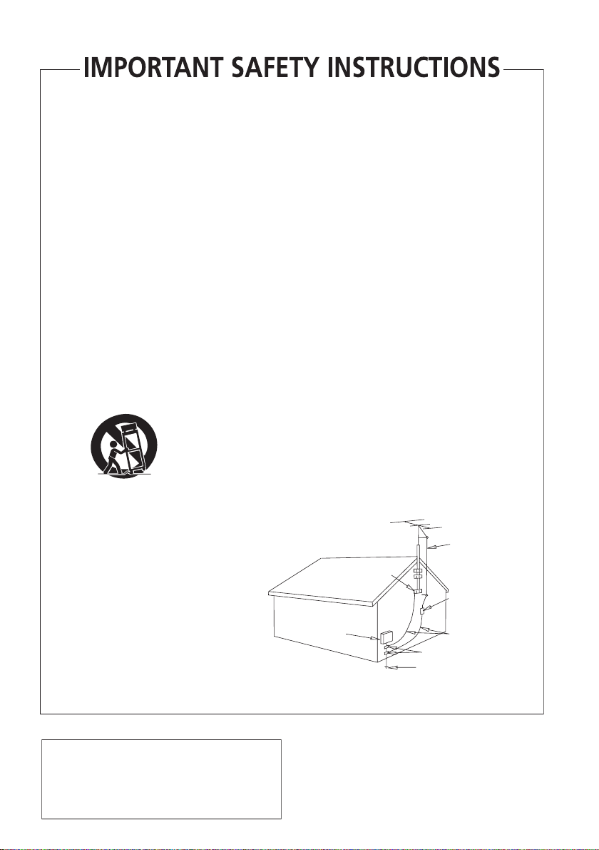
OUTDOOR ANTENNA GROUNDING — If an
outside antenna or cable system is connected to
the product, be sure the antenna or cable
system is grounded so as to provide some
protection against voltage surges and built-up
static charges. Article 810 of the National
Electrical Code, ANSI/NFPA 70, provides
information with regard to proper grounding of
the mast and supporting structure, grounding of
the lead-in wire to an antenna discharge unit,
size of grounding conductors, location of
antenna-discharge unit, connection to
grounding electrodes, and requirements for the
grounding electrode. See Figure A.
LIGHTNING — For added protection for this
product during a lightning storm, or when it is
left unattended and unused for long periods of
time, unplug it from the wall outlet and
disconnect the antenna or cable system. This
will prevent damage to the product due to
lightning and power-line surges.
POWER LINES — An outside antenna system
should not be located in the vicinity of overhead
power lines or other electric light or power
circuits, or where it can fall into such power
lines or circuits. When installing an outside
antenna system, extreme care should be taken
to keep from touching such power lines or
circuits as contact with them might be fatal.
OVERLOADING — Do not overload wall outlets,
extension cords, or integral convenience
receptacles as this can result in a risk of fire or
electric shock.
ELECTRIC
SERVICE
EQUIPMENT
Fig. A
OBJECT AND LIQUID ENTRY — Never push
objects of any kind into this product through
openings as they may touch dangerous voltage
points or short-out parts that could result in a
fire or electric shock. Never spill liquid of any
kind on the product.
SERVICING — Do not attempt to service this
product yourself as opening or removing covers
may expose you to dangerous voltage or other
hazards. Refer all servicing to qualified service
personnel.
DAMAGE REQUIRING SERVICE — Unplug this
product from the wall outlet and refer servicing
to qualified service personnel under the
following conditions:
• When the power-supply cord or plug is
damaged.
• If liquid has been spilled, or objects have fallen
into the product.
• If the product has been exposed to rain or water.
• If the product does not operate normally by
following the operating instructions. Adjust only
those controls that are covered by the operating
instructions as an improper adjustment of other
controls may result in damage and will often
require extensive work by a qualified technician
to restore the product to its normal operation.
• If the product has been dropped or damaged in
any way.
• When the product exhibits a distinct change in
performance — this indicates a need for service.
REPLACEMENT PARTS — When replacement parts
are required, be sure the service technician has
used replacement parts specified by the
manufacturer or have the same characteristics
as the original part. Unauthorized substitutions
may result in fire, electric shock, or other
hazards.
SAFETY CHECK — Upon completion of any service
or repairs to this product, ask the service
technician to perform safety checks to
determine that the product is in proper
operating condition.
WALL OR CEILING MOUNTING — The product
should not be mounted to a wall or ceiling.
HEAT — The product should be situated away from
heat sources such as radiators, heat registers,
stoves, or other products (including amplifiers)
that produce heat.
ANTENNA
LEAD IN
GROUND
CLAMP
WIRE
ANTENNA
DISCHARGE UNIT
(NEC SECTION 810-20)
GROUNDING CONDUCTORS
(NEC SECTION 810-21)
GROUND CLAMPS
POWER SERVICE GROUNDING
ELECTRODE SYSTEM
(NEC ART 250, PART H)
NEC — NATIONAL ELECTRICAL CODE
D1-4-2-2_En
This product is for general household purposes. Any
failure due to use for other than household purposes
(such as long-term use for business purposes in a
restaurant or use in a car or ship) and which
requires repair will be charged for even during the
warranty period.
K041_En
his product contains mercury. Disposal of this
material may be regulated due to environmental
considerations. For disposal or recycling information,
please contact your local authorities or the Electronics
Industries Alliance : www.eiae.org.
K057_En
Page 4
POWER-CORD CAUTION
T
Handle the power cord by the plug. Do not pull out the
plug by tugging the cord and never touch the power
cord when your hands are wet as this could cause a
short circuit or electric shock. Do not place the unit, a
piece of furniture, etc., on the power cord, or pinch the
cord. Never make a knot in the cord or tie it with other
cords. The power cords should be routed such that they
are not likely to be stepped on. A damaged power cord
can cause a fire or give you an electrical shock. Check
the power cord once in a while. When you find it
damaged, ask your nearest PIONEER authorized
service center or your dealer for a replacement.
S002_En
NOTE IMPORTANTE SUR LE CABLE
D’ALIMENTATION
enir le câble d’alimentation par la fiche. Ne pas
débrancher la prise en tirant sur le câble et ne pas
toucher le câble avec les mains mouillées. Cela risque
de provoquer un court-circuit ou un choc électrique. Ne
pas poser l’appareil ou un meuble sur le câble. Ne pas
pincer le câble. Ne pas faire de noeud avec le câble ou
l’attacher à d’autres câbles. Les câbles d’alimentation
doivent être posés de façon à ne pas être écrasés. Un
câble abîmé peut provoquer un risque d’incendie ou un
choc électrique. Vérifier le câble d’alimentation de
temps en temps. Contacter le service après-vente
PIONEER le plus proche ou le revendeur pour un
remplacement.
WARNING: Handling the cord on this product or
cords associated with accessories sold with the
product will expose you to chemicals listed on
proposition 65 known to the State of California and
other governmental entities to cause cancer and
birth defect or other reproductive harm.
Wash hands after handling
S002_Fr
D36-P4_A_En
For U.S. and Australia Model
C67-7-3_En
Ce produit est destiné à une utilisation domestique
générale. Toute panne due à une utilisation autre
qu'à des fins privées (comme une utilisation à des
fins commerciales dans un restaurant, dans un
autocar ou sur un bateau) et qui nécessite une
réparation sera aux frais du client, même pendant la
période de garantie.
K041_Fr
CAUTION – PREVENT ELECTRIC SHOCK DO
NOT USE THIS (POLARIZED) PLUG
WITH AN EXTENSION CORD.
RECEPTACLE OR OTHER OUTLET
UNLESS THE BLADES CAN BE
FULLY INSERTED TO PREVENT
BLADE EXPOSURE.
ATTENTION –
POUR PREVENIR LES CHOCS
ELECTRIQUES NE PAS UTILISER
CETTE FICHE POLARISEE AVEC UN
PROLONGATEUR UNE PRISE DE
COURANT OU UNE AUTRE SORTIE
DE COURANT, SAUF SI LES LAMES
PEUVENT ETRE INSEREES A FOND
SANS EN LAISSER AUCUNE PARTIE
A DECOUVVERT.
D2-4-4-1_EF
This Class B digital apparatus complies with Canadian ICES-003.
Cet appareil numérique de la Classe B est conforme à la norme NMB-003 du Canada.
D8-20-1_EF
Page 5
Selecting fine audio equipment such as the unit
you’ve just purchased is only the start of your
musical enjoyment. Now it’s time to consider how
you can maximize the fun and excitement your
equipment offers. This manufacturer and the
Electronic Industries Association’s Consumer
Electronics Group want you to get the most out of
your equipment by playing it at a safe level. One that
lets the sound come through loud and clear without
annoying blaring or distortion-and, most importantly,
without affecting your sensitive hearing.
Sound can be deceiving. Over time your hearing
“comfort level” adapts to higher volumes of sound.
So what sounds “normal” can actually be loud and
harmful to your hearing. Guard against this by
setting your equipment at a safe level BEFORE your
hearing adapts.
To establish a safe level:
• Start your volume control at a low setting.
• Slowly increase the sound until you can hear it
comfortably and clearly, and without distortion.
Once you have established a comfortable sound
level:
• Set the dial and leave it there.
Taking a minute to do this now will help to prevent
hearing damage or loss in the future. After all, we
want you listening for a lifetime.
We Want You Listening For A Lifetime
Used wisely, your new sound equipment will
provide a lifetime of fun and enjoyment. Since
hearing damage from loud noise is often
undetectable until it is too late, this manufacturer
and the Electronic Industries Association’s
Consumer Electronics Group recommend you avoid
prolonged exposure to excessive noise. This list of
sound levels is included for your protection.
Decibel
Level Example
30 Quiet library, soft whispers
40
Living room, refrigerator, bedroom away from traffic
50 Light traffic, normal conversation, quiet office
60 Air conditioner at 20 feet, sewing machine
70 Vacuum cleaner, hair dryer, noisy restaurant
Average city traffic, garbage disposals, alarm clock
80
at two feet.
THE FOLLOWING NOISES CAN BE DANGEROUS
UNDER CONSTANT EXPOSURE
90
Subway, motorcycle, truck traffic, lawn mower
100 Garbage truck, chain saw, pneumatic drill
120 Rock band concert in front of speakers,
thunderclap
140 Gunshot blast, jet plane
180 Rocket launching pad
Information courtesy of the Deafness Research Foundation.
S001_En
English
What’s in the box
Please confirm that the following items are all supplied.
Receiver subwoofer (SX-SW260) box:
• Remote control (page 15)
• AA/R6 dry cell batteries (to confirm operation) x2
(page 16)
• Display unit (page 14)
• Power cord (page 12)
• AM loop antenna (page 11)
• FM wire antenna (page 11)
• Display cable (page 11)
• Coaxial cable (page 27)
• Microphone (for Auto MCACC setup) (page 17)
• These operating instructions
• Warranty card
Speakers (S–ST404) box:
• Speakers (front x2, surround x2, center x1) (page 12)
• Speaker cables x5 (page 11)
• Non-skid pads (large) x4 (page 7, 8)
• Non-skid pads (small) x20 (page 7, 8)
• Speaker stands x2 (page 8)
• Screws (for speaker stands) x2 (page 8)
5
En
Page 6

Contents
Thank you for buying this Pioneer product.
Please read through these operating instructions so that you will know how to operate your model properly. After you
have finished reading the instructions, put them in a safe place for future reference
.
Contents
What’s in the box
01 Speaker Setup Guide
Safety precautions when setting up
Home theater sound setup
Standard surround setup
Front surround setup
Wall mounting the speakers
Before mounting
Wall mounting the center speaker
Wall mounting the other speakers
Additional notes on speaker placement
02 Connecting up
Basic connections
Wall mounting the display unit
Using this system for TV audio
03 Controls and displays
Display unit
Display
Remote control
Using the remote control
Putting the batteries in the remote control
04 Getting started
System demo setting
Using the Auto MCACC setup for optimal surround
. . . . . . . . . . . . . . . . . . . . . . . . . . . . . . . . . . . . .17
sound
05 Listening to your system
Auto listening mode
Listening in surround sound
Dolby Pro Logic II Music settings
Using Front Surround
Using Advanced Surround
Listening in stereo
Using the Sound Retriever
Listening with Acoustic Calibration EQ
Enhancing dialogue
Using Quiet and Midnight listening modes
Adjusting the bass and treble
Boosting the bass level
. . . . . . . . . . . . . . . . . . . . . . . . . . . . .5
. . . . . . . . . . . . . . .7
. . . . . . . . . . . . . . . . . . . . . .7
. . . . . . . . . . . . . . . . . . . . . .7
. . . . . . . . . . . . . . . . . . . . . . . . .8
. . . . . . . . . . . . . . . . . . . . .9
. . . . . . . . . . . . . . . . . . . . . . . . . . . .9
. . . . . . . . . . . . . . .9
. . . . . . . . . . . . . . .9
. . . . . . . . . . . .9
. . . . . . . . . . . . . . . . . . . . . . . . . . .10
. . . . . . . . . . . . . . . . .13
. . . . . . . . . . . . . . . . . .13
. . . . . . . . . . . . . . . . . . . . . . . . . . . . . . . .14
. . . . . . . . . . . . . . . . . . . . . . . . . . . . . . . . . . .14
. . . . . . . . . . . . . . . . . . . . . . . . . . . . . .15
. . . . . . . . . . . . . . . . . . . . . .16
. . . . . . . . .16
. . . . . . . . . . . . . . . . . . . . . . . . .17
. . . . . . . . . . . . . . . . . . . . . . . . . .19
. . . . . . . . . . . . . . . . . . . .19
. . . . . . . . . . . . . . .19
. . . . . . . . . . . . . . . . . . . . . . . . .20
. . . . . . . . . . . . . . . . . . . . .20
. . . . . . . . . . . . . . . . . . . . . . . . . . .20
. . . . . . . . . . . . . . . . . . . . .21
. . . . . . . . . . . .21
. . . . . . . . . . . . . . . . . . . . . . . . . .21
. . . . . . . .21
. . . . . . . . . . . . . . . . . . .21
. . . . . . . . . . . . . . . . . . . . . . . .22
06 Listening to the radio
Listening to the radio
Improving poor FM reception
Improving poor AM sound
Memorizing stations
Listening to station presets
Changing the frequency step
. . . . . . . . . . . . . . . . . . . . . . . . .23
. . . . . . . . . . . . . . . . . .23
. . . . . . . . . . . . . . . . . . . .23
. . . . . . . . . . . . . . . . . . . . . . . . .23
. . . . . . . . . . . . . . . . . . .23
. . . . . . . . . . . . . . . . . .24
07 Surround sound settings
Using the Setup menu
Channel level setting
Speaker distance setting
Dynamic Range Control
Dual mono setting
Adjusting the channel levels using the test tone
. . . . . . . . . . . . . . . . . . . . . . . .25
. . . . . . . . . . . . . . . . . . . . . . . .25
. . . . . . . . . . . . . . . . . . . . .25
. . . . . . . . . . . . . . . . . . . . . .25
. . . . . . . . . . . . . . . . . . . . . . . . . .26
08 Other connections
Connecting auxiliary components
Connecting an analog audio component
Listening to an external audio source
Connecting external antennas
Using this unit with a Pioneer plasma display
SR+ Setup for Pioneer plasma displays
Using the SR+ mode with a Pioneer plasma
. . . . . . . . . . . . . . . . . . . . . . . . . . . . . . . . . . .29
display
About the control out jack
. . . . . . . . . . . . . . .27
. . . . . . . . .27
. . . . . . . . . . . . .27
. . . . . . . . . . . . . . . . . .27
. . . . . . . . . .28
. . . . . . . . . . . . . . . . . . . . .29
09 Additional information
Setting the sleep timer
Dimming the display
DTS CD setting
Resetting the system
Installation and maintenance
Hints on installation
Glossary
. . . . . . . . . . . . . . . . . . . . . . . . . . . . . . . . . . .31
Setting up the remote to control your TV
Using the TV remote control buttons
Preset code list
Troubleshooting
General
. . . . . . . . . . . . . . . . . . . . . . . . . . . . . . . . . .33
Tuner
. . . . . . . . . . . . . . . . . . . . . . . . . . . . . . . . . . . .33
Error Messages
Specifications
. . . . . . . . . . . . . . . . . . . . . . . .30
. . . . . . . . . . . . . . . . . . . . . . . . .30
. . . . . . . . . . . . . . . . . . . . . . . . . . . . . .30
. . . . . . . . . . . . . . . . . . . . . . . . .30
. . . . . . . . . . . . . . . . . . .31
. . . . . . . . . . . . . . . . . . . . . . . . .31
. . . . . . . . . . .31
. . . . . . . . . . . .31
. . . . . . . . . . . . . . . . . . . . . . . . . . . .32
. . . . . . . . . . . . . . . . . . . . . . . . . . . . .33
. . . . . . . . . . . . . . . . . . . . . . . . . . . .34
. . . . . . . . . . . . . . . . . . . . . . . . . . . . . . .35
. . . . .26
. . . . . .28
6
En
Page 7
Speaker Setup Guide
01
Chapter 1
Speaker Setup Guide
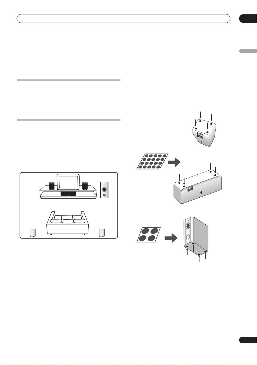
1 Attach the smaller non-skid pads to the base of
Safety precautions when setting up
When assembling the speakers, lay them down flat on
their side to avoid accidents or injury. Make sure to use a
stable surface when assembling, setting up, and placing
the speakers.
Home theater sound setup
Depending on the size and characteristics of your room,
you can place your speakers in one of two ways using this
system.
Standard surround setup
This is a standard multichannel surround sound speaker
setup for optimal 5.1 channel home theater sound.
Surround
left
Front
left
Center
Listening position
Listening position
Front
right
Receiver subwoofer
Surround
right
each of the front, surround and center speakers. The
four large non-skid pads are for the receiver
subwoofer (as shown).
Use the adhesive side of the pads to attach them to the
base (flat surface) of each speaker.
Non-skid pads
(small) x 20
English
Front and surround speakers
Center speaker
Non-skid pads
(large) x 4
Receiver subwoofer
2 Connect the speaker system.
Refer to
Connecting up
After connecting everything, place the speakers as
shown in the diagram (left) for optimal surround sound.
After placing the speakers, run the Auto MCACC setup
(page 17) to complete your surround sound setup.
to connect the speakers properly.
7
En
Page 8
01
Speaker Setup Guide
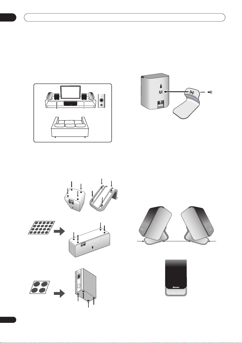
Front surround setup
This setup is ideal when rear surround speaker
placement isn't possible or you want to avoid running
long speaker cables in your listening area. Use this setup
together with the Front Surround modes in page 20 to
take advantage of wall and ceiling reflections for a very
realistic surround effect.
Front right
Surround
right
subwoofer
Receiver
Surround left
Front left
Center
Listening position
1 Attach the smaller non-skid pads to the base of
the front and center speakers and to the speaker
stands. The four large non-skid pads are for the
receiver subwoofer (as shown).
Use the adhesive side of the pads to attach them to the
base (flat surface) of each speaker or stand.
2 Attach the surround speakers to the speaker
stands.
For each speaker, line up the spurs on the stand with the
holes on the back of the speaker and insert, then secure
the speaker to the stand with the screw provided.
3 Connect the speaker system.
Refer to
Connecting up
to connect the speakers properly.
After connecting everything, place the speakers as
shown in the diagram (left) for optimal surround sound
(the surround speakers are next to the front speakers).
4 Turn the speakers as shown, following the guide
marks for optimal Front Surround.
If you have selected
or
FRTMUSIC
FRTMOVIE
(Front Surround Movie)
(Front Surround Music), turn each
surround speaker so that the guide markers on the stand
base are lined up horizontally in the direction the
listening position (see below). With
EXTPOWER
(Extra
Power), the surround speakers should point in the same
direction as the front speakers (see below).
See
Using Front Surround
on page 20 for more
information.
Speaker stands
Center speaker
Receiver
subwoofer
FRTMOVIE / FRTMUSIC
EXTPOWER
Non-skid pads
(small) x 20
Non-skid pads
(large) x 4
Front speakers
After placing the speakers, run the Auto MCACC setup
(page 17) to complete your surround sound setup.
8
En
Page 9
Speaker Setup Guide
01
Caution
• Please don’t attach the surround speakers to the wall
for Front surround setup.
Wall mounting the speakers
Before mounting
• Remember that the speaker system is heavy and that
its weight could cause the screws to work loose, or
the wall material to fail to support it, resulting in the
speaker falling. Make sure that the wall you intend to
mount the speakers on is strong enough to support
them. Do not mount on plywood or soft surface walls.
• Mounting screws are not supplied. Use screws
suitable for the wall material and support the weight
of the speaker.
Caution
• If you are unsure of the qualities and strength of the
wall, consult a professional for advice.
• Pioneer is not responsible for any accidents or
damage that result from improper installation.
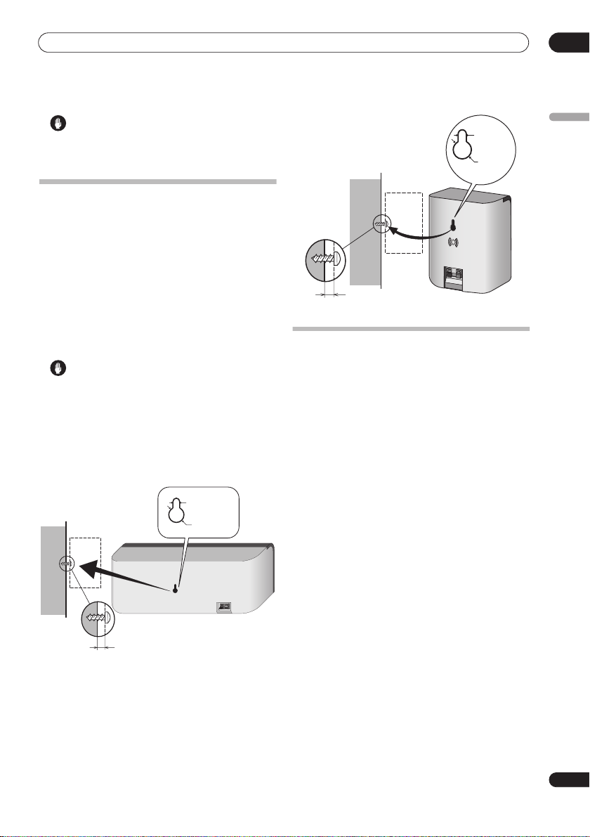
Wall mounting the center speaker
The center speaker has a mounting hole which can be
used to mount the speaker on the wall.
5 mm/3/16 in
10 mm/3/8 in
5 mm to 7 mm (3/16 in. to 1/4 in.)
Wall mounting the other speakers
In addition to the center speaker, the front and surround
speakers also have holes for wall mounting. However, if
you are using the Front Surround setup described on the
previous page, do not wall mount the surround speakers.
5 mm/
3/16 in.
10 mm/
3/8 in.
English
5 mm to 7 mm (3/16 in. to 1/4 in.)
Additional notes on speaker placement
• Install the main front left and right speakers at an
equal distance from the TV.
• For optimum effect, install the rear speakers slightly
above ear level.
• Install the center speaker above or below the TV so
that the sound of the center channel is localized at
the TV screen.
Precautions:
• When installing the center speaker on top of the TV,
be sure to secure it with tape or some other suitable
means. Otherwise, the speaker may fall from the TV
due to external shocks such as earthquakes,
endangering those nearby or damaging the speaker.
• The front (L/R), center and surround (L/R) speakers
supplied with this system are magnetically shielded.
However, depending on the installation location,
color distortion may occur if the speaker is installed
extremely close to the screen of a television set. If this
happens, turn the power switch of the television set
OFF, and turn it ON after 15 min to 30 min. If the
problem persists, place the speaker system away
from the television set.
• The receiver subwoofer is not magnetically shielded
and so should not be placed near a TV or monitor.
Magnetic storage media (such as floppy discs and
tape or video cassettes) should also not be kept close
to the receiver subwoofer.
• Do not attach the receiver subwoofer to the wall or
ceiling. They may fall off and cause injury.
• For safety, make sure that there is no exposed bare
speaker wire outside of the speaker terminals.
• Do not connect the supplied speakers with any other
amplifier. This may result in malfunction or fire.
• Do not connect any speakers other than those
supplied to this system.
9
En
Page 10
02
Connecting up
Chapter 2
Connecting up
Basic connections
Important
• When connecting this system or changing connections, be sure to switch power off and disconnect the power
cord from the wall socket.
After completing all connections, connect the power cord to the wall socket.
Receiver subwoofer
FM antenna
AM loop antenna
2
10
En
SYSTEM CONNECTOR
USE ONLY WITH DISPLAY UNIT.
SEE INSTRUCTION MANUAL.
AC IN
3
Display unit
ANTENNA
CONTROL IN
MCACC
SETUP MIC
CONTROL
SPEAKERS
OUT
SUB WOOFER
CENTER
SURROUND
RL
FRONT
RL
(COAXIAL)
DVD
FM
UNBALAMLOOP ANTENNA75Ω
(OPTICAL)
DIGITAL
AUDIO INPUT
DTV
(OPTICAL)
ANALOG
AUXPC/GAME
L
R
1
Display cable
Page 11
Connecting up
02
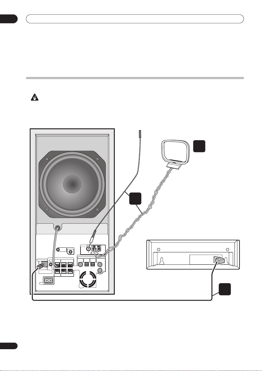
1 Connect the display unit to the receiver subwoofer.
Plug the L-shaped end of the display cable into the
connector on the rear of the display unit, then plug the
other end of the display cable into
CONNECTOR
jack on the receiver subwoofer.
SYSTEM
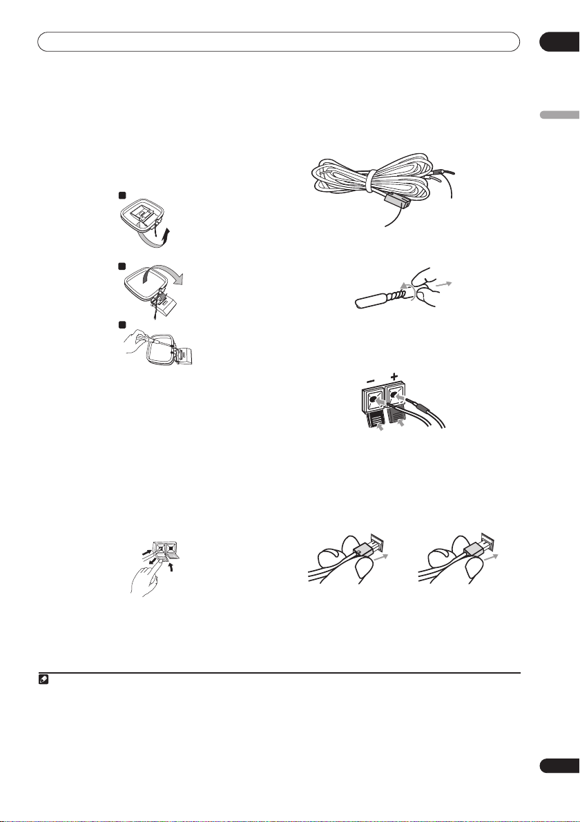
2 Assemble the AM loop antenna.
a
b
c
a. Bend the stand in the direction indicated by the
arrow.
b. Clip the loop onto the stand.
c. If you want to fix to a wall or other surface, perform
step b after first securing the stand with screws.
It is recommended that you determine the reception
strength before securing the stand with the screws.
3 Connect the AM and FM antennas1.
a. Connect one wire of the AM loop antenna to each AM
antenna terminal
2
.
For each terminal, press down on the tab to open;
insert the wire, then release to secure.
4 Connect each speaker.
• Each speaker cable has a color-coded connector at
one end and two wires at the other end.
Color-coded wire
Color-coded connector
(Connect to rear panel)
(Connect to speaker)
• Twist and pull off the protective shields on each wire.
• Connect the wires to the speaker. Match the colored
wired with the color-coded label (model label), then
+
insert the colored wire into the red (
other wire into the black (
–
) side.
) side and the
• Connect the other end to the color-coded speaker
terminals on the rear of the receiver subwoofer. Make
sure to insert completely.
The small lug at the wire-end of the speaker plug
should face up or down depending on whether it’s
being plugged into one of the upper or lower speaker
terminals. Please make sure to connect correctly.
English
1
2
3
b. Push the FM antenna
plug onto the center pin of the
FM antenna socket.
Note
1• Keep antenna cables away from other cables, the display unit and receiver subwoofer.
• If reception with the supplied antenna is poor, see
external antennas
2• Don’t let it come into contact with metal objects and avoid placing near computers, television sets or other electrical appliances.
• The signal earth () is designed to reduce noise that occurs when an antenna is connected. It is not an electrical safety earth.
• If radio reception is poor, you may be able improve it by re-inserting each antenna wire into the opposite terminal.
• For best reception, do not untwist the AM loop antenna wires or wrap them around the loop antenna.
3• To ensure optimum reception, make sure the FM antenna is fully extended and not coiled or hanging at the rear of the unit.
on page 27.
Improving poor FM reception
Upper terminal Lower terminal
5 Connect the subwoofer cable.
• Just below the subwoofer speaker, to the left of
center, you should see the subwoofer connecting
cable. Plug this into the
SUBWOOFER SPEAKER
terminal.
and
Improving poor AM sound
on page 23 or
Connecting
11
En
Page 12
02
Connecting up
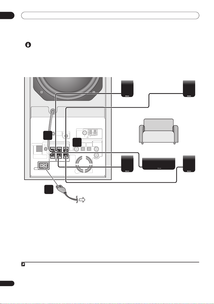
Caution
• These speaker terminals carry
voltage
. To prevent the risk of electric shock when
HAZARDOUS LIVE
connecting or disconnecting the speaker cables,
disconnect the power cord before touching any
uninsulated parts.
Receiver subwoofer
ANTENNA
CONTROL IN
MCACC
SYSTEM CONNECTOR
USE ONLY WITH DISPLAY UNIT.
SEE INSTRUCTION MANUAL.
AC IN
CONTROL
SETUP MIC
5
SPEAKERS
OUT
SUB WOOFER
SURROUND
RL
CENTER
FRONT
RL
4
(COAXIAL)
FM
UNBAL
AUDIO INPUT
DIGITAL
DTV
DVD
(OPTICAL)
(OPTICAL)
• Do not connect any speakers other than those
supplied to this system.
• Do not connect the supplied speakers to any
amplifier other than the one supplied with this
system. Connection to any other amplifier may result
in malfunction or fire.
Surround right
(Gray)
AM
LOOP ANTENNA75Ω
ANALOG
AUXPC/GAME
L
R
Front right
Listening position
Center (Green)
(Red)
Surround left
(Blue)
Front left
(White)
7
To AC outlet
6 If you have a DVD player or other source1
component you want to connect, connect it now before
connecting the power cord in the next step.
See
Connecting auxiliary components
to connect a digital source component.
7 Connect the power cords.
• Connect the power cords to AC inlets on the receiver
subwoofer. Connect the power cords to a wall socket.
Note
1 Make sure to connect a TV or monitor (for video sources) to take advantage of this system’s home theater potential. Please refer to the instruc-
tion manual supplied with your TV or monitor for connection details.
2• Do not use any power cord other than the one supplied with this system.
• Do not use the supplied power cord for any purpose other than connecting to this system.
12
En
on page 27 for how
2
Page 13
Connecting up
02
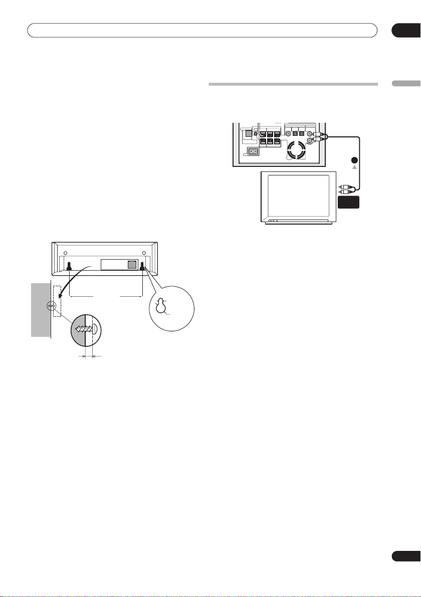
Wall mounting the display unit
It is possibe to mount the display unit on the wall.
Before mounting:
• Remember that the display unit is heavy and could
cause the wood screws to work loose, or the wall
material to fail to support it, resulting in the display
falling. Make sure that the wall you intend to mount
the display on is strong enough to support it. Do not
mount on plywood or soft surface walls.
• Mounting screws are not supplied. Use screws that
are suitable for the wall material and that will support
the weight of the display.
•Pioneer bears no responsibility for accidents resulting
from faulty assembly or installation, insufficient
mounting strength of walls or other building fixtures,
misuse or natural disasters.
• If you are unsure of the qualities and strength of the
wall, consult a professional for advice.
5 27/32 in.
148.5 mm
Mounting screw
(not supplied)
3/32 in./ 2.5 mm
5/32 in.
4 mm
3/8 in.
10 mm
Using this system for TV audio
If your TV has a stereo audio output you can connect it to
this system and enjoy surround TV sound.
AUDIO INPUT
DIGITAL
CONTROL
SPEAKERS
SYSTEM CONNECTOR
OUT
SUB WOOFER
SURROUND
RL
USE ONLY WITH DISPLAY UNIT.
SEE INSTRUCTION MANUAL.
CENTER
FRONT
RL
AC IN
1 Connect the AUDIO OUTPUT jacks on your TV to the
AUX AUDIO INPUT jacks on the receiver subwoofer.
Use the red/white stereo audio cable (not supplied) for
this connection. Make sure you match the left and right
outputs with their corresponding inputs for correct
stereo sound.
• You can use the
AUX
source you want, such as a tape deck, etc.
ANALOG
DTV
DVD
AUXPC/GAME
(OPTICAL)
(COAXIAL)
(OPTICAL)
L
R
1
AUDIO
OUTPUT
TV
input jacks for any analog
English
13
En
Page 14
03
Controls and displays
Chapter 3
Controls and displays
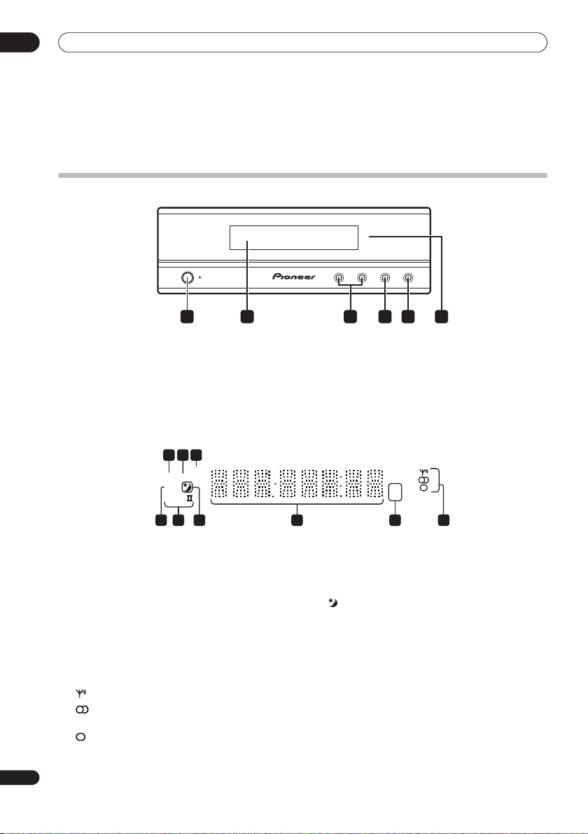
Display unit
STANDBY/ON
1 4 652 3
1
STANDBY/ON
Press to switch the system on/into standby.
2 Front panel display
See below for details.
3
VOLUME
Use to adjust the volume.
buttons
Display
2 3
1
SOUND
DTS F.SURR.
2D
2PL
789
1
DTS
Lights during playback of a DTS source (page 19).
2
F.SURR.
Lights when one of the Front Surround listening
modes is selected (page 20).
SURR.
Lights when one of the Advanced Surround listening
modes is selected (page 20).
3 SOUND
Lights when Sound Retriever is active (page 20).
4 Tuner indicators
– Lights when a broadcast is being received.
– Lights when a stereo FM broadcast is being
received in auto stereo mode.
– Lights when FM mono reception is selected.
– VOLUME + AUDIO INPUT SURROUND
4
AUDIO INPUT (page 27)
Press repeatedly to select one of the external audio
inputs (
DVD, DTV, PC/GAME
5
SURROUND
Use to select a Surround mode (page 19).
6 IR remote sensor
6
5 kHz / MHz
Indicates the frequency unit shown in the character
display (
6 Character display
7
Lights when sleep timer is active (page 30).
82 PL II
Lights during Dolby Pro Logic II decoding (page 19).
92 D
Lights during playback of a Dolby Digital source
(page 19).
kHz
for AM,
kHz
MHz
5 4
(page 16)
MHz
for FM).
or
AUX
).
14
En
Page 15
Controls and displays
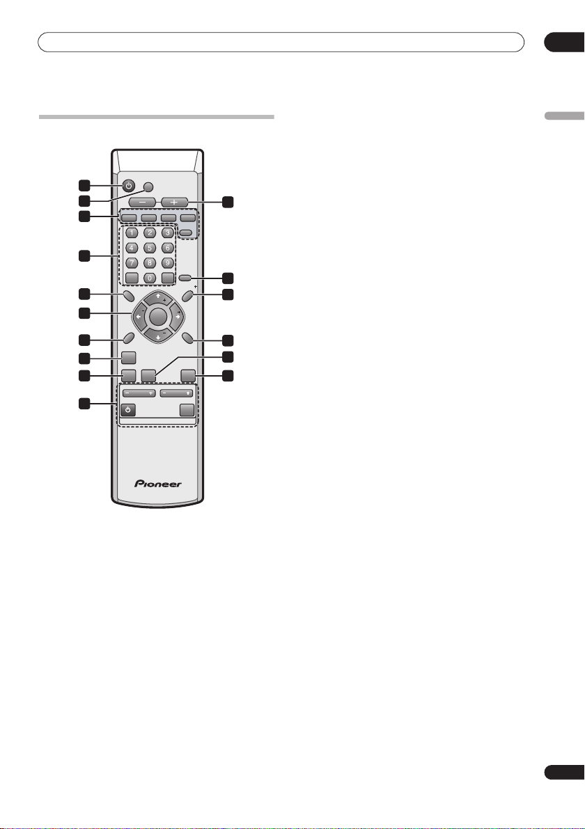
Remote control
STANDBY/ON
DVD DTV
ENTER
SETUP
ST
SOUND
SOUND
RETRIEVER
CHANNEL
TV
DVD
DTV
MUTE
VOLUME
TUNE
ENTER
TUNE
TV CONTROL
input.
input.
PC/GAME
CLEAR
ST
VOLUME
AUX
TUNER
3
SLEEP
6
SR
8
TEST
TONE
11
14
MCACCADVANCEDSURROUND
15
INPUT
PC/GAME
)
1
2
4
5
7
9
10
12
13
16
1
STANDBY/ON
Press to switch the receiver subwoofer on or into
standby.
2
MUTE
Press to mute all audio from the speakers. Press again to
cancel and restore the sound.
3
VOLUME
+/–
Use to adjust the volume.
4 Input select buttons
DVD
Press to select the
DTV
Press to select the
PC/GAME
Press to select the PC/game console (
input.
AUX
(page 28)
Press to select the auxilliary (
(page
23)
TUNER
AUX
) input.
Press to select the built-in radio tuner.
5 Numeric buttons, CLEAR and ENTER
Use the number buttons for entering radio stations
directly, and so on.
Use
CLEAR to clear an entry and start again.
ENTER to confirm an entry.
Use
6
SLEEP
Press to set the sleep timer (page 30).
7
SETUP
Use to access the menu system for surround sound
setup, tuner settings and so on (page 17, 23, 24, 25, 30).
8 SR+
Use to setup the SR+ features and to select the SR+
mode (page 29).
9
///
(cursor buttons) and
ENTER
Use to navigate the receiver subwoofer menus.
10
SOUND
(page 21)
Press to access the sound menu, from which you can
adjust bass and treble, etc.
11
TEST TONE
Use to output the test tone (for speaker setup) (page 26).
12 SOUND RETRIEVER
Press to restore CD quality sound to compressed stereo
audio sources (page 21).
13
SURROUND
Use to select a Surround mode (page 19).
14
ADVANCED
Use to select a Pioneer original surround mode
(page 20).
15
MCACC
Starts the Auto MCACC setup (page 17).
16 TV CONTROL
(page 31)
After setting up, use these controls to control your TV.
03
English
15
En
Page 16
03
Controls and displays
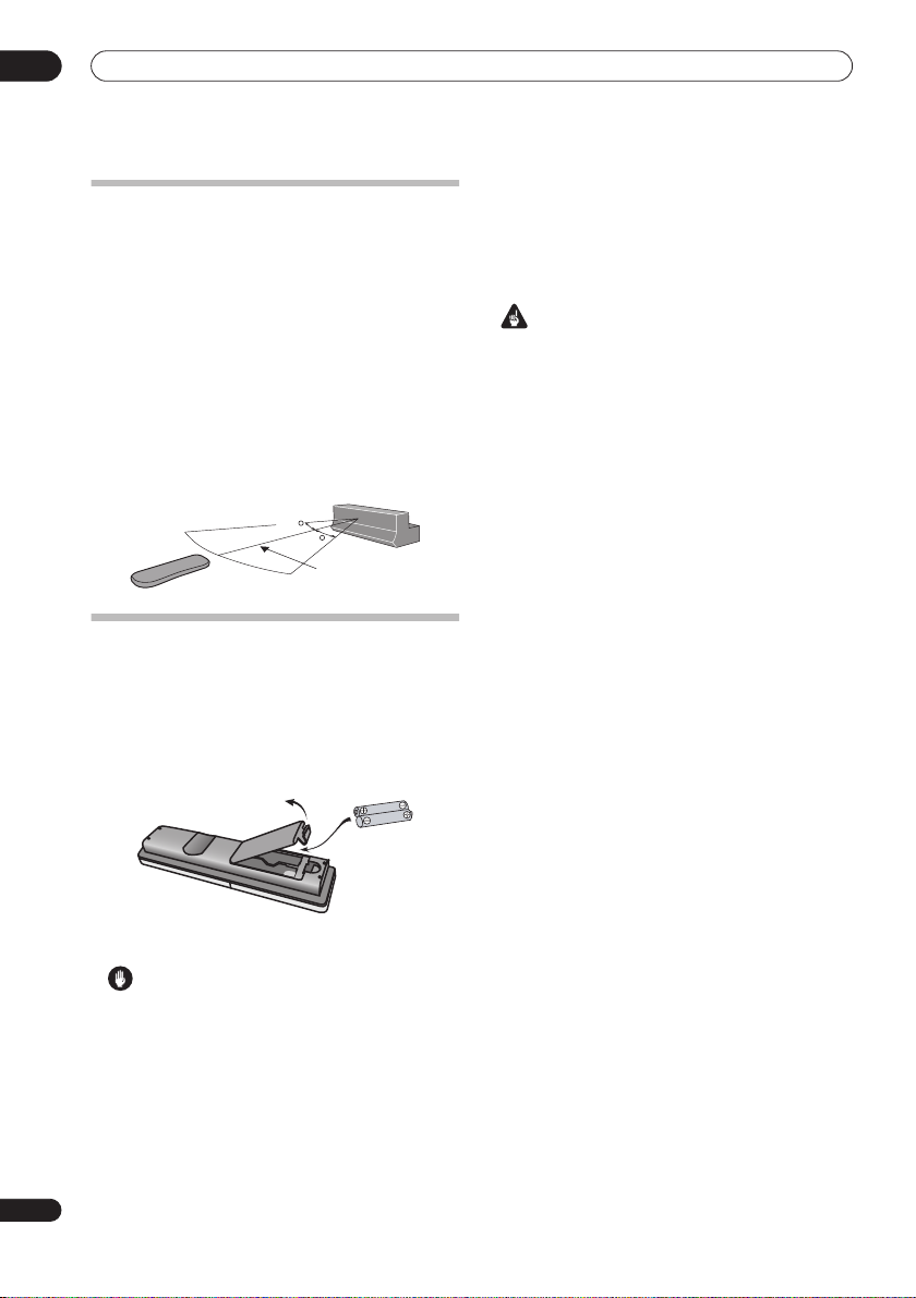
Using the remote control
Please keep in mind the following when using the remote
control:
• Make sure that there are no obstacles between the
remote and the remote sensor on the unit.
• Remote operation may become unreliable if strong
sunlight or fluorescent light is shining on the unit’s
remote sensor.
• Remote controllers for different devices can interfere
with each other. Avoid using remotes for other
equipment located close to this unit.
• Replace the batteries when you notice a fall off in the
operating range of the remote.
• Use within the operating range in front of the remote
control sensor on the display unit, as shown.
30
30
23 ft.
Putting the batteries in the remote
control
1 Open the battery compartment cover on the back of
the remote control.
2 Insert two AA/R6 batteries into the battery
compartment following the indications (
the compartment.
,
• Remove batteries from equipment that isn’t going to
be used for a month or more.
• When disposing of used batteries, please comply
with governmental regulations or environmental
public instruction’s rules that apply in your country or
area.
WARNING
• Do not use or store batteries in direct sunlight or
other excessively hot place, such as inside a car or
near a heater. This can cause batteries to leak,
overheat, explode or catch fire. It can also reduce the
life or performance of batteries.
) inside
16
En
3 Close the cover.
Caution
Incorrect use of batteries can result in hazards such
as leakage and bursting. Please observe the
following:
• Don’t mix new and old batteries together.
• Don’t use different kinds of battery together—
although they may look similar, different batteries
may have different voltages.
• Make sure that the plus and minus ends of each
battery match the indications in the battery
compartment.
Page 17

Getting started
04
Chapter 4
Getting started
System demo setting
Switches the automatic demo feature on or off (this
starts when you plug in for the first time).
SLEEP
ENTER
CLEAR
SETUP
SOUND
SOUND
RETRIEVER
1Switch the system into standby.
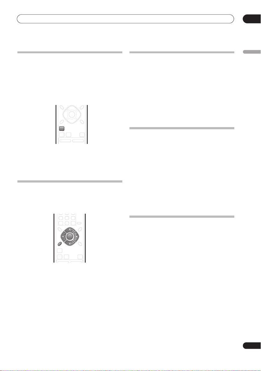
2 Press
SETUP
.
3 Use the
/
(cursor left/right) buttons to select
DEMO from the menu, then press
/
4 Use the
setting, then press
(cursor up/down) buttons to select a
ENTER
Select from:
DEMO ON
•
•
DEMO OFF
– Switches the demo display on.
– Switches the demo display off and the
system into standby.
SR
TUNE
ST
ST
ENTER
TEST
TONE
TUNE
MCACCADVANCEDSURROUND
ENTER
.
.
Using the Auto MCACC setup for
optimal surround sound
The Multichannel Acoustic Calibration (MCACC) system
measures the acoustic characteristics of your listening
area, taking into account ambient noise, and testing for
channel delay and channel level. After you have set up
the microphone provided, the system uses the
information from a series of test tones to optimize the
speaker settings and equalization (Acoustic Calibration
EQ) for your particular room.
Important
• The test tones used for Auto MCACC setup are loud;
however, do not turn the volume down during setup
as this may result in a sub-optimal setup.
• Make sure the microphone and speakers are not
moved during the MCACC setup.
STANDBY/ON
MUTE
VOLUME
DVD DTV
PC/GAME
1 Connect the microphone to the MCACC SETUP MIC
jack on the rear panel.
MCACC
SETUP MIC
CONTROL
SPEAKERS
SYSTEM CONNECTOR
OUT
SUB WOOFER
RL
USE ONLY WITH DISPLAY UNIT.
SEE INSTRUCTION MANUAL.
CENTER
RL
AC IN
1
SETUP
SOUND
SOUND
AUX
TUNER
CONTROL IN
SURROUND
FRONT
RETRIEVER
CHANNEL
ANTENNA
FM
UNBALAMLOOP ANTENNA75Ω
AUDIO INPUT
ANALOG
DIGITAL
DTV
DVD
AUX
PC/GAME
(OPTICAL)
(COAXIAL)
(OPTICAL)
L
R
SR
TUNE
ST
ST
ENTER
TEST
TONE
TUNE
MCACCADVANCEDSURROUND
VOLUME
English
2 Place the microphone at your normal listening
position.
Place the mic horizontally about ear level at your normal
listening position using a table or chair.
Make sure there are no obstacles between the speakers
and the microphone.
Note
1 You only need to use the Auto MCACC setup once (unless you change the placement of your speakers or your room layout).
17
En
Page 18

04
Getting started
3 If the receiver subwoofer is off, press
ON
to turn the power on.
MCACC
4 Press
.
Try to be as quiet as possible after pressing
STANDBY/
MCACC
. The
volume increases automatically and the system outputs
a series of test tones.
• To cancel Auto MCACC setup before it has finished,
press
MCACC
. The unit will continue to use the
previous settings.
• If the ambient noise level is too high,
the display for five seconds. To exit and check the
noise levels
ENTER
• If you see an
when
1
, press
MCACC
RETRY
shows in the display.
ERR MIC
or
ERR SP
NOISY
blinks in
, or to try again, press
message in the
display, there may be a problem with your mic or the
speaker connections. To try again, press
when you see
RETRY
2
ENTER
When the MCACC setup is complete, the volume level
returns to normal,
Acoustic Calibration EQ is activated.
COMPLETE3 shows in the display, and
4
Note
1• If the room environment is not optimal for the Auto MCACC setup (too much ambient noise, echo off the walls, obstacles blocking the speakers from
the microphone) the final settings may be incorrect. Check for household appliances (air conditioner, fridge, fan, etc.), that may be affecting the environment and switch them off if necessary.
• Some older TVs may interfere with the operation of the mic. If this seems to be happening, switch off the TV during Auto MCACC setup.
18
En
2 If this doesn’t work, press
3 If
COMPLETE
4 See
Listening with Acoustic Calibration EQ
MCACC
doesn’t appear, it is likely an error occurred during the setup. Please check all connections and try again.
, turn off the power, and check the problem indicated by the
on page 21 to switch on/off Acoustic Calibration EQ.
ERR
message, then try the Auto MCACC setup again.
Page 19
Listening to your system
05
Chapter 5
Listening to your system
•
AUTO
– Auto listening mode (see above)
•
Auto listening mode
The Auto listening mode is the simplest way to listen to
any source as it was mastered: the output from the
speakers mirrors the channels in the source material.
If you set up the system for Front surround (page 8), the
Front Surround modes will give the best results (see
Using Front Surround
• Press
SURROUND
on page 20).
ST
ST
ENTER
SOUND
SOUND
RETRIEVER
TV
CHANNEL
TEST
TONE
TUNE
MCACCADVANCEDSURROUND
VOLUME
INPUT
to select the AUTO listening
mode.
If the source is Dolby Digital or DTS, the front panel 2 D
or
DTS
indicator lights.
• You can also use the
SURROUND
button on the
display unit to change the listening mode.
Listening in surround sound
You can listen to stereo or multichannel sources in
surround sound. Surround sound is generated from
stereo sources using one of the Dolby Pro Logic
decoding modes.
If you set up the system for Front surround (page 8), the
Front Surround modes will give the best results (see
Using Front Surround
• Press
SURROUND
mode.
• You can also use the
display unit to change the listening mode.
The choices that appear in the display will vary according
to the type of source that’s playing.
If the source is Dolby Digital or DTS, the front panel
or
DTS
indicator lights.
on page 20).
ST
ST
ENTER
SOUND
SOUND
RETRIEVER
TV
CHANNEL
TEST
TONE
TUNE
MCACCADVANCEDSURROUND
VOLUME
INPUT
repeatedly to select a listening
SURROUND
button on the
2
D
DOLBY PL
sound for use with any two-channel source
MOVIE
•
surround sound, especially suited to movie sources,
for use with any two-channel source
•
MUSIC
surround sound, especially suited to music sources,
for use with any two-channel source; see
Logic II Music settings
STEREO
•
Dolby Pro Logic II Music settings
When listening in Dolby Pro Logic II Music mode (see
above), there are three settings you can adjust: Center
Width, Dimension, and Panorama.
1With Dolby Pro Logic II Music mode active, press
SOUND
2 Use
DIMEN. or PANORAMA then press
•
C WIDTH
the front speakers by spreading the center channel
between the front right and left speakers, making it
sound wider (higher settings) or narrower (lower
settings)
•
DIMEN.
surround sound balance from front to back, making
the sound more distant (minus settings), or more
forward (positive settings)
•
PANORAMA
include the surround speakers for a ‘wraparound’
effect.
3 Use
then press
(Dolby Pro Logic) – 4.1 channel surround
(Dolby Pro Logic II Movie) – 5.1 channel
(Dolby Pro Logic II Music) – 5.1 channel
– See
Listening in stereo
.
/
(cursor left/right) to select C WIDTH,
(Center Width): Provides a better blend of
(Dimension): Adjusts the depth of the
: Extends the front strereo image to
/
(cursor up/down) to adjust the setting
ENTER
to confirm.
SETUP
SOUND
RETRIEVER
English
on page 20
ENTER
.
Dolby Pro
19
En
below
ENTER
SOUND
SLEEP
CLEAR
SR
TUNE
ST
ST
ENTER
TEST
TONE
TUNE
MCACCADVANCEDSURROUND
Page 20
05
Listening to your system
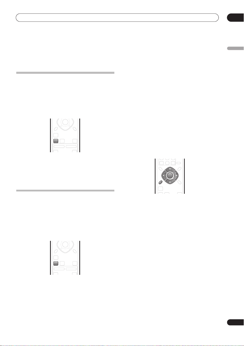
Using Front Surround
The Front Surround modes are effective when you are
using the Front surround speaker setup as described on
page 8. The surround speakers should be placed beside
the front speakers and oriented either towards the walls,
or straight ahead, depending on which mode you are
using (see below).
ST
ST
ENTER
SOUND
SOUND
RETRIEVER
CHANNEL
TV
• Press
ADVANCED
to select a Front Surround mode.
Press repeatedly to select
EXTPOWER
.
• If you have selected
Movie) or
FRTMUSIC
each surround speaker so that the guide markers on
the stand base are lined up horizontally in the
direction the listening position (see below). With
EXTPOWER
(Extra Power), the surround speakers
should point in the same direction as the front
speakers (see below).
FRTMOVIE / FRTMUSIC
TEST
TONE
TUNE
MCACCADVANCEDSURROUND
VOLUME
INPUT
FRTMOVIE, FRTMUSIC
FRTMOVIE
(Front Surround
or
(Front Surround Music), turn
EXTPOWER
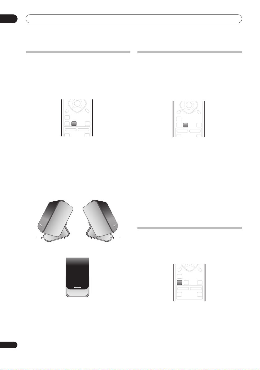
Using Advanced Surround
The Advanced Surround effects can be used with any
multichannel or stereo source for a variety of additional
surround sound effects.
If you set up the system for Front surround (page 8), the
Front Surround modes will give the best results (see
Using Front Surround
• Press
ADVANCED
above).
ST
ST
ENTER
CHANNEL
TEST
TONE
TUNE
MCACCADVANCEDSURROUND
VOLUME
INPUT
SOUND
RETRIEVER
SOUND
TV
to select an Advanced Surround
mode.
Press repeatedly to select:
• ADVMOVIE
• ADVMUSIC
• EXPANDED
• TV SURR.
– Suitable for movies
– Suitable for music
– Wide sound field
– Surround sound for mono or stereo TV
broadcasts
• SPORTS
• GAME
• VIRTUAL
– Suitable for sports programming
– Suitable for TV game units
– A virtual surround effect using just the
subwoofer and front speakers.
•
5 STEREO
– Powerful surround sound for stereo
music sources
Listening in stereo
You can listen to any source—stereo or multichannel—in
stereo. When playing a multichannel source, all
channels are downmixed to the front left/right speakers
and the subwoofer.
SOUND
SOUND
RETRIEVER
CHANNEL
TV
• Press
SURROUND
repeatedly until STEREO shows in
the display.
• You can also use the
display unit to change the listening mode.
TEST
TONE
TUNE
MCACCADVANCEDSURROUND
VOLUME
INPUT
TV CONTROL
SURROUND
button on the
20
En
Page 21
Listening to your system
05
Using the Sound Retriever
When audio data is removed during the MP3 or WMA
compression process, sound quality often suffers from
an uneven sound image. The Sound Retriever feature
employs new DSP technology that helps bring CD quality
sound back to compressed 2-channel audio by restoring
sound pressure and smoothing jagged artifacts left over
after compression.
TUNE
ST
ST
ENTER
SOUND
SOUND
RETRIEVER
CHANNEL
•While listening to a stereo source, press
RETRIEVER
.
Press repeatedly to switch between:
RTRV ON
•
•
— Switches the Sound Retriever on.
RTRV OFF
— Switches the Sound Retriever off.
TEST
TONE
TUNE
MCACCADVANCEDSURROUND
VOLUME
SOUND
Enhancing dialogue
The Dialogue Enhancement feature is designed to make
the dialogue stand out from other background sounds in
a TV or movie sound track.
1 Press SOUND.
2 Use the
DIALOGUE then press ENTER.
3 Use the
the amount dialogue enhancement then press
ENTER to confirm.
Select between
Using Quiet and Midnight listening
modes
The Quiet listening feature reduces excessive bass or
treble in a sound source.
The Midnight listening feature allows you to hear
effective surround sound of movies at low volume levels.
1 Press SOUND.
2 Use the
Listening with Acoustic Calibration EQ
You can listen to sources using the Acoustic Calibration
EQ set in
Using the Auto MCACC setup for optimal
surround sound
1 Press
2 Use the
MCACC EQ then press
3 Use the
EQ ON or EQ OFF then press
• On the
speaker settings (channel delay and channel level)
remains as it is set.
on page 17.
TUNE
ST
ENTER
TUNE
CHANNEL
ENTER
SLEEP
CLEAR
ST
VOLUME
.
ENTER
SR
TEST
TONE
MCACCADVANCEDSURROUND
to confirm.
ENTER
SETUP
SOUND
SOUND
RETRIEVER
SOUND
.
/
(cursor left/right) buttons to select
/
(cursor up/down) buttons to switch
EQ OFF
setting, equalization is set to off and
TONE then press ENTER.
3 Use the
QUIET or MIDNIGHT then press ENTER to confirm.
• To cancel the Quiet or Midnight listening modes,
Adjusting the bass and treble
Use the bass and treble controls to adjust the overall
tone.
1 Press SOUND.
2 Use the
TONE then press ENTER.
3 Use the
BASS/TRE then press ENTER.
• Selecting
4 Use the
BASS or TREBLE; use the
buttons to adjust the sound then press ENTER to
confirm.
• Acoustic Calibration EQ is set to on automatically
after Auto MCACC setup is used.
/
(cursor left/right) buttons to select
/
(cursor up/down) buttons to select
OFF, MID
or
MAX
.
/
(cursor left/right) buttons to select
/
(cursor up/down) buttons to select
select
BASS/TRE
.
/
(cursor left/right) buttons to select
/
(cursor up/down) buttons to select
BASS/TRE
cancels the Quiet and Midnight
listening modes. These modes cannot be used at the
same time.
/
(cursor left/right) buttons to select
/
(cursor up/down)
English
21
En
Page 22

05
Listening to your system
Boosting the bass level
There are two bass modes you can use to enhance the
bass in a source.
1 Press
SOUND
.
2 Use the
BASSMODE then press
3 Use the
sound then press
Select between
/
(cursor left/right) buttons to select
ENTER
.
/
(cursor up/down) buttons to select the
ENTER
to confirm.
OFF, MUSIC
or
CINEMA
.
22
En
Page 23

Listening to the radio
06
Chapter 6
Listening to the radio
Improving poor AM sound
Listening to the radio
The tuner can receive both FM and AM broadcasts, and
lets you memorize your favorite stations so you don’t have
to manually tune in every time you want to listen.
TUNER
SLEEP
ENTER
CLEAR
SETUP
SOUND
SOUND
RETRIEVER
1 Press
TUNER
to switch to the tuner, then press
repeatedly to select the FM or AM band.
The display shows the band and frequency.
2 Tune to a frequency.
There are three tuning modes—manual, auto, and highspeed:
•
Manual tuning
: Press
change the displayed frequency.
•
Auto tuning
: Press and hold
frequency display starts to move, then release. The
tuner will stop on the next station it finds. Repeat to
keep searching.
•
High-speed tuning
the frequency display starts to move rapidly. Keep the
button held down until you reach the frequency you
want. If necessary, fine tune the frequency using the
manual tuning method.
Improving poor FM reception
If you’re listening to an FM station in stereo but the
reception is weak, you can improve the sound quality by
switching to mono.
1 Tune to an FM radio station then press
/
2 Use the
FM MODE then press
3 Use the
MONO
then press
The mono indicator ( ) lights when the tuner is in mono
reception mode.
FM AUTO
Select
mode (the stereo indicator ( ) lights when receiving a
stereo broadcast).
(cursor left/right) buttons to choose
ENTER
/
(cursor up/down) buttons to select
ENTER
above to switch back to auto-stereo
SR
TUNE
ST
ST
ENTER
TEST
TONE
TUNE
TUNE +/–
TUNE +/–
: Press and hold
.
.
repeatedly to
until the
TUNE +/–
SETUP
The simplest way to improve the sound quality of AM
radio is to make sure that the TV in the room is switched
off. Also try changing the position and direction of the
AM loop antenna.
Changing the noise cut mode
If you find that the sound quality is bad even after trying
the above, you may be able to improve it using a different
noise cut mode. Just choose the one that sounds best.
1 Tune to an AM radio station then press
2 Use the
NOISECUT then press
3 Use the
Noise cut mode (1, 2 or 3) then press
Memorizing stations
You can save up to 30 station presets so that you always
have easy access to your favorite stations without having
to tune in manually each time.
1 Tune to an AM or FM radio station.
For the FM band, select mono or auto-stereo reception as
necessary. This setting is saved along with the preset.
2 Press
SETUP
3 Use the
ST.MEM. then press
until
4 Use the
station preset you want then press
Listening to station presets
1Make sure the tuner function is selected.
2 Use the
• Alternatively, use the number buttons to select a
preset directly.
.
FM
SETUP
/
(cursor left/right) buttons to choose
ENTER
.
/
(cursor up/down) buttons to select a
ENTER
.
/
(cursor left/right) buttons to choose
ENTER
.
/
(cursor up/down) buttons to select the
ST +/–
buttons to select a station preset.
ENTER
.
English
.
.
23
En
Page 24

06
Listening to the radio
Changing the frequency step
If you find that you can’t tune into stations successfully,
the frequency step may not be suitable for your country/
region.
1Switch the system into standby.
SETUP
2 Press
3 Use the
‘AM 9K/10K’, then press
4 Use the
setting then press
•
AM 9K
50 kHz step for FM
•
AM 10K
100 kHz step for FM
.
/
(cursor left/right) buttons to select
ENTER
.
/
(cursor up/down) buttons to select a
ENTER
– 9 kHz step for AM;
– 10 kHz step for AM;
to confirm.
24
En
Page 25

Surround sound settings
07
Chapter 7
Surround sound settings
5 Press
ENTER
Using the Setup menu
From the Setup menu you can access all the surround
sound settings of the system
speaker distances, dynamic range adjustment and dual
mono audio playback.
Use the following buttons to use the Setup menu.
1
, including channel levels,
• If you use the Auto MCACC feature again, it will
overwrite the settings you have made here.
Speaker distance setting
The Auto MCACC feature (see page 17) should give you
the best surround sound setup. However you may find
that by further adjustment of the speaker distance
settings you can improve the surround sound in your
listening room.
Set the distance of each speaker from your normal
listening position.
1 Press
2 Use the
DISTANCE, then press
3 Use
(cursor up/down) to adjust the distance.
Adjust the following speakers:
•
L
– Front left speaker
C
– Center speaker
•
R
– Front right speaker
•
•
SR
SL
– Surround left speaker
•
•
SW
Each speaker can be adjusted from
4 Press
• If you use the Auto MCACC feature again, it will
overwrite the settings you have made here.
Dynamic Range Control
When watching Dolby Digital or DTS material at low
volume, low level sounds—including some of the
dialog—can be difficult to hear properly. Using one of the
Dynamic Range Control (DRC) settings can help by
bringing up the low level sounds, while controlling high
level peaks.
/
Dynamic Range Control works only with Dolby Digital
soundtracks and some DTS soundtracks.
1 Press
2 Use the
DRC, then press
CHANNEL
SLEEP
CLEAR
SR
TUNE
ST
ST
ENTER
TEST
TONE
TUNE
MCACCADVANCEDSURROUND
VOLUME
SETUP
SOUND
RETRIEVER
ENTER
SOUND
Channel level setting
The Auto MCACC feature (see page 17) should give you
the best surround sound setup. However you may find
that by further adjustment of the channel levels you can
improve the surround sound in your listening room.
This method of setting the channel levels allows you to
listen to a source and adjust the levels of each playback
channel. Note that the channel level settings for stereo
playback are independent of the settings for surround
sound playback.
A further method of setting the channel levels is to use
the test tone method. See
using the test tone
1 Select stereo or multichannel playback for a source.
2 Press
SETUP
3 Use the
CH LEVEL
4 Use
(cursor up/down) to adjust the level of that channel.
/
, then press
/
(cursor left/right) to select a channel;
• You can adjust the level of each channel by ± 10 dB.
• If the system is in Stereo or Virtual mode, or a stereo
source is playing in Auto mode, you will not be able
to adjust the center or surround channels.
Adjusting the channel levels
on page 26 for more on this.
.
(cursor left/right) buttons to select
ENTER
.
3 Use
Select one of the following:
Note
1 There are other settings you can adjust from the Setup menu; these are explained in
tion
on page 30.
when you’re finished.
SETUP
.
/
(cursor left/right) buttons to select
/
(cursor left/right) to select a speaker;
– Surround right speaker
– Subwoofer
ENTER
when you’re finished.
SETUP
.
/
(cursor left/right) buttons to select
ENTER
/
(cursor up/down) to select a setting.
Listening to the radio
ENTER
.
on page 23 and
English
.
/
1 FT
to
30 FT
.
Additional informa-
25
En
Page 26

07
Surround sound settings
•
DRC OFF (default)
– No dynamic range adjustment
(use when listening at higher volume)
•
DRC MID
– Mid setting
DRC HIGH
•
– Dynamic range is reduced (loud sounds
are reduced in volume while quieter sounds are
increased)
4 Press
ENTER
to exit.
Dual mono setting
Specifies how dual mono encoded Dolby Digital or DTS
soundtracks should be played. You can also use this
setting to switch the audio channel on DVD-RW discs
recorded with bilingual audio.
1 Press
SETUP
.
2 Use the
DUALMONO, then press
3 Use
Select one of the following:
•
•
•
4 Press
/
(cursor left/right) buttons to select
ENTER
.
/
(cursor up/down) to select a setting.
CH1 MONO (default)
CH2 MONO
CH1/CH2
– Both channels are played through the
– Only channel 1 is played
– Only channel 2 is played
front speakers
ENTER
to exit.
Adjusting the channel levels using the
test tone
If you prefer, you can set the channel levels using a test
tone as a reference, rather than playing a source (see
Channel level setting
through each speaker in turn, allowing you to adjust the
level as it plays.
Note that the channel level settings for stereo sources
are independent of the settings for surround sound
sources.
1 Press
SURROUND
mode.
• If you want to set the channel levels for stereo (two
channel) playback, select the
mode.
2 Press
TEST TONE
The test tone is output from each speaker in turn.
3While a test tone is playing, use the
up/down) buttons to adjust that channel level.
The aim is to adjust the levels so that you hear the test
tone at the same volume from each speaker. You can
adjust the level of each channel by ± 10 dB.
• You can adjust the overall volume of test tone output
using the
the channel level settings).
• If the system is in Stereo or Virtual mode, you will not
be able to adjust the center or surround channels.
• Because of the ultra low frequencies the subwoofer
produces, it may sound quieter than it really is. We
suggest adjusting the subwoofer level while listening
to a source. See the method described in
level setting
4When you’re done, press
setup.
• If you use the Auto MCACC feature again, it will
overwrite the settings you have made here.
on page 25). A test tone is played
SLEEP
ENTER
CLEAR
SETUP
SOUND
RETRIEVER
SOUND
CHANNEL
TV
SR
TUNE
ST
ST
ENTER
TEST
TONE
TUNE
MCACCADVANCEDSURROUND
VOLUME
INPUT
to select the Auto listening
STEREO
.
VOLUME +/–
buttons (this does not affect
on page 25.
ENTER
to exit test tone
listening
/
(cursor
Channel
26
En
Page 27

Other connections
08
Chapter 8
Other connections
Important
• When connecting this system or changing
connections, be sure to switch power off and
disconnect the power cord from the wall socket.
After completing all connections, connect the power
cord to the wall socket.
Connecting auxiliary components
The receiver subwoofer has several digital inputs for
digital playback components, such as DVD, CD and MD
players.
ANTENNA
CONTROL IN
MCACC
SETUP MIC
FM
UNBALAMLOOP ANTENNA
75Ω
AUDIO INPUT
ANALOG
CONTROL
SYSTEM CONNECTOR
OUT
SUB WOOFER
USE ONLY WITH DISPLAY UNIT.
SEE INSTRUCTION MANUAL.
CENTER
AC IN
DVD player, etc.
• Connect the digital output jack on your CD
recorder, etc. to one of the DIGITAL input jacks on
the receiver subwoofer.
Use a commercially available optical cable or supplied
coaxial cable to make this connection.
Connecting an analog audio component
You can use the
audio component, such as a tape player. See
system for TV audio
(this explains connecting the audio output from your TV,
but any analog audio component can be connected).
AUX
on page 13 for connection details
DIGITAL
SPEAKERS
DTV
DVD
(COAXIAL)
(OPTICAL)
(OPTICAL)
DIGITAL OUT
(COAXIAL)
DIGITAL OUT
(OPTICAL)
AUXPC/GAME
L
R
or
SURROUND
RL
FRONT
RL
input jacks to connect an analog
Using this
Listening to an external audio source
You can connect both analog and digital external audio
sources to this system. Digital audio sources include
digital satellite receivers, CD recorders, etc. Analog
sources include your TV. See also
components
above.
STANDBY/ON
DVD DTV PC/GAME AUX
1 If the system isn’t already on, press
ON
to switch on.
Connecting auxiliary
MUTE
VOLUME
TUNER
STANDBY/
Also make sure that the external source (TV, satellite
receiver, etc.) is switched on.
2 Select DVD, DTV, PC/GAME or AUX to select the
source for playback.
These buttons correspond with the input jacks on the
receiver subwoofer.
3 If necessary, start playback of the external source.
Connecting external antennas
For an external AM antenna, use 5–6 meters of vinylinsulated wire and set up either indoors or outdoors.
Leave the loop antenna connected.
Outdoor antenna
Indoor
antenna
(vinyl-coated
wire)
15ft. to 18ft.
(5m to 6m)
AM
LOOP ANTENNA
English
27
En
Page 28

08
SETUP
TUNER
Other connections
For an external FM antenna, Use a PAL connector to hook
up an external FM antenna.
• Use a 3-ringed miniplug SR+ cable to connect the
CONTROL IN jack of this unit (through a media
receiver, if applicable) to the CONTROL OUT jack of
your plasma display.
Before you can use the extra SR+ features, you need to
make a few settings in the unit—see
ANTENNA
PAL connector
Pioneer plasma displays
SR+ Setup for Pioneer plasma displays
Make the following settings if you have connected a
Pioneer plasma display to this unit using an SR+ cable.
Using this unit with a Pioneer plasma
display
If you have a Pioneer plasma display1, you can use an
SR+ cable
of various convenient features, such as controlling this
unit via the plasma display’s remote sensor, automatic
video input switching of the plasma display, display unit
messages appearing on the plasma display screen, and
automatic volume muting on the plasma display.
2
to connect it to this unit and take advantage
Media receiver
CONTROL
OUT
Pioneer plasma display
ANTENNA
CONTROL IN
MCACC
SETUP MIC
FM
UNBALAMLOOP ANTENNA
75Ω
AUDIO INPUT
DIGITAL
SYSTEM CONNECTOR
USE ONLY WITH DISPLAY UNIT.
SEE INSTRUCTION MANUAL.
AC IN
CONTROL
SPEAKERS
OUT
SURROUND
SUB WOOFER
RL
CENTER
FRONT
RL
ANALOG
DTV
DVD
AUXPC/GAME
(OPTICAL)
(COAXIAL)
(OPTICAL)
L
R
1 Press SR+.
2 Use the
choose SETUP, then press ENTER.
3 Use the
choose the setting you want to adjust.
The current setting is shown for each option as you cycle
through the display. See below for a full list and
description of each.
4 Use the
the setting.
5 Repeat steps 3 and 4 to make other settings.
6 When you’re done, press ENTER to leave the SR+
setup menu.
3
SR+ Setup for
below.
CHANNEL
SLEEP
CLEAR
SR
TUNE
ST
ST
ENTER
TEST
TONE
TUNE
MCACCADVANCEDSURROUND
VOLUME
ENTER
SETUP
SOUND
SOUND
RETRIEVER
/
(cursor left/right) buttons to
/
(cursor left/right) buttons to
/
(cursor up/down) buttons to adjust
Important
• With an SR+ cable connected, the remote must now
be pointed towards your plasma display rather than
the display unit of the receiver subwoofer in order to
control the receiver subwoofer.
Automatic plasma display volume muting
When Volume Control is switched on, the volume of the
plasma display is automatically muted when the receiver
subwoofer is switched on, or the receiver subwoofer’s
input function is changed to one that you would want to
hear the sound from the receiver subwoofer rather than
the plasma display (DVD, for example).
Note
1 This system is compatible with all Pioneer plasma displays from 2003 onward.
2 The 3-ringed SR+ cable from Pioneer is commercially available under the part number ADE7095. Contact the Pioneer Customer Support division for
more information on obtaining an SR+ cable.
3 You won’t be able to use the remote sensor of this unit with the
display. You can use the remote sensor of the plasma display (even in standby) as long as the power isn’t switched off.
28
En
CONTROL IN
jack of this unit connected to the
CONTROL OUT
jack of your plasma
Page 29

Other connections
•
VOL.C ON
input function is changed, the volume on the plasma
display is muted so only sound from this unit is
heard.
•
VOL.C OFF
the plasma display
Automatic plasma display input switching
In order that the plasma display can switch automatically
to the correct input when you switch the input function of
the receiver subwoofer, you need to tell it how your
system is connected.
For example, if you connected your DVD player to the
DVD
your plasma display, select the
so that when you switch the input function of the receiver
subwoofer to
display will automatically switch to input 2.
For each receiver subwoofer input function (
PC(PC/GAME), AUX
NONE
•
PDP1
•
one of the numbered inputs (1 to 5)
•
TVTN
TV tuner
• The number of video inputs available will depend on
the plasma display you’ve connected.
• The
on your plasma display.
• The SR+ setting remains in effect even in standby.
• The SR+ setting does not affect the FM/AM tuner
function.
– When this unit is switched on, or the
– This unit does not control the volume of
input on the receiver subwoofer, and to input 2 on
DVD
to watch your DVD player, the plasma
) you can select:
– does not switch the plasma display input
to
PDP5
– switches the plasma display input to
– switches the plasma display to its built-in
Note
PDP5
input may be called ‘PC Input’ (or similar)
DVD PDP2
setting here
DVD, DTV
Note
• You can control this unit with the plasma display’s
remote sensor even in standby, but you can’t control
this unit with either this unit’s remote sensor or the
plasma display’s remote sensor when the plasma
display is switched off (AC off) and the SR+ cable is
connected to the
CONTROL IN
jack of this unit.
About the control out jack
Many Pioneer components have SR CONTROL jacks
which can be used to link components together so that
you can use just the remote sensor of one component.
When you use a remote control, the control signal is
passed along the chain to the appropriate component.
Note that if you use this feature, make sure that you also
have at least one set of analog or coaxial digital audio
jacks connected to another component for grounding
,
purposes.
• Connect the CONTROL IN jack on another Pioneer
component to the CONTROL OUT jack on the
receiver subwoofer.
This will allow you to control the other component (such
as a DVD recorder in a cabinet) by pointing its remote at
the display unit supplied with this receiver subwoofer.
• You can also connect this receiver subwoofer to your
plasma display as described above, in which case
you should point the remote at the plasma display to
control your DVD player, receiver subwoofer, and
plasma display.
Use a cable with a mono mini-plug on each end for the
connection.
08
English
Using the SR+ mode with a Pioneer plasma
display
1 Press SR+ on the remote.
/
2 Use
then press ENTER.
• The SR+ setting is maintained even after switching
the receiver subwoofer into standby then back on.
Automatic muting and input switching will be
effective when the receiver subwoofer is switched on.
• If you disconnect the SR+ cable or switch the plasma
display off while SR+ is on, the
remains.
• To switch to
SR+ OFF
(cursor left/right) to select SR+ ON
SR+ ON
setting
SR+ OFF
.
, follow steps 1 and 2, selecting
29
En
Page 30

09
Additional information
Chapter 9
Additional information
Setting the sleep timer
The sleep timer switches off the receiver subwoofer after
a specified time so you can fall asleep without worrying
1
about it.
DVD DTV
PC/GAME
AUX
TUNER
SLEEP
ENTER
CLEAR
SR
TUNE
ST
ST
ENTER
1 Press the
SETUP
SLEEP
button to select an option.
Choose between the following options:
•
SLP ON
– Switches off after about an hour
SLP OFF
•
After selecting
– Cancels the sleep timer
SLP ON
, you can press
SLEEP
again to
check how much time is left. Each line indicates
approximately 12 minutes (remaining):
SLP -----
Dimming the display
SETUP
SOUND
RETRIEVER
ENTER
SOUND
SLEEP
CLEAR
SR
TUNE
ST
ST
ENTER
TEST
TONE
TUNE
DTS CD setting
If you play a DTS-encoded CD, you will need to change
this setting to hear the decoded signal.
1Switch the system into standby.
2 Press
SETUP
.
3 Use the
CD TYPE from the menu, then press
4 Use the
setting, then press
/
(cursor left/right) buttons to select
/
(cursor up/down) buttons to select a
ENTER
.
ENTER
.
Select from:
NORMAL
•
– Use for playback of regular audio CDs.
Some DTS-encoded CDs will output noise when
played.
•
DTS-CD
– Use for playback of DTS-encoded CDs, but
note that the beginning of regular CD tracks may be
skipped.
Resetting the system
Use this procedure to reset all system settings to the
factory default.
1Switch the system on.
2 Press and hold SURROUND then press the
STANDBY/ON button on the display unit.
The next time you switch on, all the system settings
should be reset.
You can choose to dim the display if you find it too
2
bright.
1 Press
SETUP
.
/
2 Use the
DIMMER
3 Use the
LIGHT or DARK then press
Note
1 The display dims when the sleep timer is set.
2 The display dims when the sleep timer is set, regardless of this setting.
30
En
(cursor left/right) buttons to select
then press
ENTER
.
/
(cursor up/down) buttons to select
ENTER
.
Page 31

Additional information
VOLUME
09
Installation and maintenance
Hints on installation
We want you to enjoy using this system for years to come,
so please bear in mind the following points when
choosing a location:
Do...
Use in a well-ventilated room.
Place on a solid, flat, level surface, such as a table, shelf or
stereo rack
.
Don’t...
Use in a place exposed to high temperatures or humidity,
including near radiators and other heat-generating
appliances.
Place on a window sill or other place where the system will
be exposed to direct sunlight.
Use in an excessively dusty or damp environment.
Place directly on top of an amplifier, or other component in
your stereo system that becomes hot in use.
Use near a television or monitor as you may experience
interference—especially if the television uses an indoor
antenna.
Use in a kitchen or other room where the system may be
exposed to smoke or steam.
Use on a thick rug or carpet, or cover with cloth—this may
prevent proper cooling of the system unit.
Place on an unstable surface, or one that is not large enough
to support all four of the system unit’s feet.
Glossary
Dolby Digital
A multi-channel audio encoding system developed
by Dolby Laboratories that enables far more audio
to be stored on a disc than PCM encoding.
Setting up the remote to control your
TV
You can use the supplied remote to control your TV. To be
able to use this feature you first have to program the
remote with a maker code from the table on the following
page.
DVD DTV
PC/GAME
AUX
TUNER
ENTER
CLEAR
ST
TUNE
ENTER
TUNE
TV CONTROL
SR
ST
TEST
TONE
MCACCADVANCEDSURROUND
VOLUME
INPUT
CLEAR
button, then enter
TV
SETUP
SOUND
SOUND
RETRIEVER
CHANNEL
TV
1 Switch on your TV.
2 Press and hold down the
the maker code for your TV.
• If the maker’s name of your TV doesn’t appear in the
table, you will not be able to use this remote to
control your TV.
3 Point the remote towards your TV and press
to check that the remote works with your TV.
If the remote is set up correctly, the TV should switch off.
If it doesn’t and there is another code given for your
maker, repeat step
2
with a new code.
English
Dolby
Pro Logic II
DTS
A matrix decoding technology developed by Dolby
Laboratories that expands any two-channel source
audio, such as CDs and TV broadcasts, to a fivechannel playback (left/center/right/left surround/
right surround), resulting in a surround
experience.
A multi-channel audio encoding system developed
by Digital Theater Systems that enables far more
audio to be stored on a disc than PCM encoding.
Manufactured under license from Dolby Laboratories.
“Dolby”, “Pro Logic” and the double-D symbol are
trademarks of Dolby Laboratories.
“DTS” and “DTS Digital Surround” are registered
trademarks of Digital Theater Systems, Inc.
Using the TV remote control buttons
The table below shows how to use this remote control
with your TV.
Button
TV
INPUT
TV VOLUME
TV CHANNEL
What it does
Press to switch the TV on/off (standby)
Press to change the TV’s video input
Use to adjust the TV volume
Use to change TV channels
31
En
Page 32

09
Additional information
Preset code list
Please note that there are cases where only certain functions may be controllable after assigning the proper preset code, or the
codes for the manufacturer in the list will not work for the model that you are using.
Manufacturer
ACURA
ADMIRAL
AIWA
AKAI
AKURA
ALBA
AMSTRAD
ANITECH
ASA
ASUKA
AUDIOGONIC
BASIC LINE
BAUR
BEKO
BEON
BLAUPUNKT
BLUE SKY
BLUE STAR
BPL
618
BRANDT
BTC
641
BUSH
CASCADE
CATHAY
CENTURION
CGB
642
CIMLINE
CLARIVOX
CLATRONIC
CONDOR
CONTEC
CROSLEY
CROWN
CRYSTAL
CYBERTRON
DAEWOO
DAINICHI
DANSAI
DAYTON
DECCA
DIXI
607, 644
DUMONT
ELIN
ELITE
ELTA
EMERSON
ERRES
FERGUSON
FINLANDIA
FINLUX
653, 654, 655
FIRSTLINE
FISHER
FORMENTI
Code(s)
644
631
660
632, 635, 642
641
607, 639, 641, 644
642, 644, 647
644
645
641
607, 636
641, 644
631, 607, 642
638
607
631
641
618
636
607, 641, 642, 644, 647, 656
644
607
607
644
607
638
638
644
632
638, 644
642
641
607, 644, 656
641
607
644
607, 648
653
607
641
644
642
607
607, 636, 651
635, 643, 655
632, 607, 645, 648,
640, 644
632, 635, 638, 645
632, 607, 642
Manufacturer
FRONTECH
FRONTECH/PROTECH
FUJITSU
FUNAI
GBC
632, 642
GE
601, 608, 607, 610, 617, 602, 628,
618
GEC
607, 634, 648
GELOSO
GENEXXA
GOLDSTAR
650
GOODMANS
GORENJE
GPM
GRAETZ
GRANADA
GRADIENTE
GRANDIN
GRUNDIG
HANSEATIC
HCM
HINARI
HISAWA
HITACHI
654, 606, 610, 624, 625, 618
HUANYU
HYPSON
ICE
646, 647
IMPERIAL
INDIANA
INGELEN
INTERFUNK
INTERVISION
ISUKAI
ITC
642
ITT
631, 632, 642
JEC
605
JVC 613, 623
KAISUI 618, 641, 644
KAPSCH 631
KENDO 642
KENNEDY 632, 642
KORPEL 607
KOYODA 644
LEYCO 607, 640, 646, 648
LIESENK&TTER 607
LOEWE 607
LUXOR 632, 642, 643
M-ELECTRONIC 631, 644, 645, 654,
655, 656, 607, 636, 651
MAGNADYNE 632, 649
MAGNAFON 649
Code(s)
631, 642, 646
648, 629
640, 646, 658
632, 644
641
631, 642
618, 644
607, 641, 644
618
631, 633, 634, 636, 642, 643,
607, 618, 646
607
631
641
632
631, 641
610, 623, 621, 602, 607,
607, 639, 647, 648, 656
638
607, 635, 642, 643, 648
630, 657
618
631, 653
607, 642
656
638, 642
631, 632, 607, 642
646, 649
Manufacturer
MAGNAVOX 607, 610, 603, 612,
629
MANESTH 639, 646
MARANTZ 607
MARK 607
MATSUI 607, 639, 640, 642, 644,
647, 648
MCMICHAEL 634
MEDIATOR 607
MEMOREX 644
METZ 631
MINERVA 631, 653
MITSUBISHI 609, 610, 602, 621,
631
MULTITECH 644, 649
NEC 659
NECKERMANN 631, 607
NEI 607, 642
NIKKAI 605, 607, 641, 646, 648
NOBLIKO 649
NOKIA 632, 642, 652
NORDMENDE 632, 636, 651, 652
OCEANIC 631, 632, 642
ORION 632, 607, 639, 640
OSAKI 641, 646, 648
OSO 641
OSUME 648
OTTO VERSAND 631, 632, 607,
642
PALLADIUM 638
PANAMA 646
PANASONIC 631, 607, 608,642,
622
PATHO CINEMA 642
PAUSA 644
PHILCO 632, 642
PHILIPS 631, 607, 634, 656
PHOENIX 632
PHONOLA 607
PROFEX 642, 644
PROTECH 607, 642, 644, 646, 649
QUELLE 631, 632, 607, 642, 645,
653
R-LINE 607
RADIOLA 607
RADIOSHACK 610, 623, 621, 602
RBM 653
RCA 601, 610, 615, 616, 617, 618,
661, 662, 609
REDIFFUSION 632, 642
REX 631, 646
ROADSTAR 641, 644, 646
SABA 631, 636, 642, 651
SAISHO 639, 644, 646
Code(s)
Manufacturer
SALORA 631, 632, 642, 643
SAMBERS 649
SAMSUNG 607, 638, 644, 646
SANYO 635, 645, 648, 621, 614
SBR 607, 634
SCHAUB LORENZ 642
SCHNEIDER 607, 641, 647
SEG 642, 646
SEI 632, 640, 649
SELECO 631, 642
SHARP 602, 619, 627
SIAREM 632, 649
SIEMENS 631
SINUDYNE 632, 639, 640, 649
SKANTIC 643
SOLAVOX 631
SONOKO 607, 644
SONOLOR 631, 635
SONTEC 607
SONY 604
SOUNDWAVE 607
STANDARD 641, 644
STERN 631
SUSUMU 641
SYSLINE 607
TANDY 631, 641, 648
TASHIKO 634
TATUNG 607, 648
TEC 642
TELEAVIA 636
TELEFUNKEN 636, 637, 652
TELETECH 644
TENSAI 640, 641
THOMSON 636, 651, 652, 663
THORN 631, 607, 642, 645, 648
TOMASHI 618
TOSHIBA 605, 602, 626, 621, 653
TOWADA 642
ULTRAVOX 632, 642, 649
UNIVERSUM 631, 607, 638, 642, 645,
646, 654, 655
VESTEL 607
VICTOR 613
VOXSON 631
WALTHAM 643
WATSON 607
WATT RADIO 632, 642, 649
WHITE
WESTINGHOUSE 607
YOKO 607, 642, 646
ZENITH 603, 620
PIONEER 600, 631, 632, 607, 636, 642,
651
Code(s)
32
En
Page 33

Additional information
09
Troubleshooting
Incorrect operations are often mistaken for trouble and malfunctions. If you think that there is something wrong with
this component, check the points below. Sometimes the trouble may lie in another component. Investigate the other
components and electrical appliances being used. If the trouble cannot be rectified even after exercising the checks
listed below, ask your nearest Pioneer authorized service center or your dealer to carry out repair work.
• If the system does not operate normally due to external effects such as static electricity disconnect the plug from
the outlet and insert again to return to normal operating conditions.
• For audio-related problems, please also check the settings of the audio playback device. See the operating
instructions for the device for detailed information.
General
Problem
The power does not
turn on, or switches off
suddenly (an error
message may be
displayed at startup).
No sound is output
when an input function
is selected.
No sound from
surround or center
speakers.
Can’t operate using the
remote control.
Remedy
• Leave the unit plugged in, wait for one minute, then switch back on.
• Make sure there are no loose strands of wire touching the unit. This could cause the system to
shut off automatically.
• Check that the speakers are connected correctly.
• Make sure there is enough space for ventilation around the receiver subwoofer.
• Make sure the voltage of the mains power source is correct for the model.
• Try reducing the volume level.
• If the problem persists, take it to your nearest Pioneer authorized service center or your dealer for
servicing.
• If you’re using the line input, make sure the component is connected correctly (see
auxiliary components
• Turn up the volume.
• Press
MUTE
• Refer to
• Check that you haven’t selected the
sound
on page 19).
• Connect the speakers properly (refer to Connecting up).
• Replace the batteries (
• Operate within 23 ft., 30° of the remote sensor (
• Remove any obstacles or operate from another position.
• Avoid exposing the remote sensor on the front panel to direct light.
• For operating the DVD recorder or other Pioneer component connected to the
jack of this receiver subwoofer, make sure that the control cable and coaxial cable or at least one set
of analog audio cables are connected. (page 29)
• If the receiver subwoofer is connected to a Pioneer plasma display with an SR+ cable, check that
the plasma display is switched on. Point the remote control at the plasma display in order to operate
the receiver subwoofer.
• Check that nothing is mistakenly plugged into the
on page 27).
on the remote control to turn muting off.
Channel level setting
on page 25 to check the speaker levels.
AUTO, STEREO
Putting the batteries in the remote control
, or
VIRTUAL
mode (see
Using the remote control
CONTROL IN
on page 16).
jack.
on page 16).
Connecting
Listening in surround
CONTROL OUT
English
Tuner
Problem
Considerable noise in
radio broadcasts.
Remedy
• Connect the AM antenna (refer to the Connecting up) and adjust the direction and position for
best reception. You may also connect an additional internal or external AM antenna (refer to
Connecting external antennas
• Fully extend the FM wire antenna, position for best reception, and secure to a wall. You may also
connect an outdoor FM antenna (see
• Turn off other equipment that may be causing the noise or move it further away.
on page 27).
Connecting external antennas
on page 27).
33
En
Page 34

09
Additional information
Problem
Auto tuning does not
pick up some stations.
Remedy
• The radio signal is weak. Auto tuning will only detect radio stations with a good signal. For more
sensitive tuning, connect an outdoor antenna.
Error Messages
Message Description
2CH ONLY
96K
MUTING
EXIT
NOISY
ERR MIC
ERR SP
EEP ERROR
NO SPTYP
• An operation is prohibited because it is only applicable to 2 channel sources, while the current
source is a multichannel source.
• An operation is prohibited because the source is 96 kHz digital.
• An operation is prohibited because the sound is muted (press
• Appears when a menu is automatically exited after a set period of inactivity.
• Background noise is too high to complete MCACC setup successfully.
• An error occurred during MCACC setup because the microphone is not connected or is not
connected properly.
• An error occurred during MCACC setup because the speakers are not connected or are not
connected properly.
• Contact your Pioneer authorized service center or your dealer for servicing.
• Try switching the unit off then on again. If the error still appears, please contact a Pioneer
authorized service center or your dealer.
MUTE
).
34
En
Page 35

Additional information
09
Specifications
SX-SW260 Audio Multi-channal Receiver
Subwoofer
•Amplifier section
RMS Power Output :
Front, Center, Surround ........................100 W per channel
Subwoofer .......................100 W (100 Hz, 10 % T.H.D., 4 Ω)
FTC Power Output :
Front, Center, Surround ..........................25 W per channel
Subwoofer ............30 W (45 Hz to 200 Hz, 1 % T.H.D., 4 Ω)
•FM tuner section
Frequency range................................ 87.5 MHz to 108 MHz
Antenna.................................................... 75
•AM tuner section
Frequency range................................. 530 kHz to 1 700 kHz
Antenna...........................................................Loop antenna
• Subwoofer section
Enclosure ............................................ Bass-reflex floor type
System.................................................. 16 cm 1-way system
Speaker....................................................... 16 cm cone type
Nominal impedance........................................................ 4
Frequency range ........................................ 25 Hz to 1.0 kHz
Maximum Input Power................................................100 W
•Miscellaneous
Power requirements.................................. AC 120 V / 60 Hz
Power consumption ......................................................41 W
Power consumption in standby...................................0.2 W
Dimensions
........................7-7/8 in. (W) x 14-3/4 in. (H) x 17-3/16 in. (D)
Weight .......................................................19 lb 14 oz/9.0 kg
• Accessories
Remote control .................................................................... 1
Display unit .......................................................................... 1
AA/R6 dry cell batteries
(to confirm operation) ......................................................... 2
Display cable........................................................................ 1
AM loop antenna .................................................................1
FM wire antenna ................................................................. 1
Microphone (for Auto MCACC setup)................................ 1
Coaxial cable........................................................................ 1
Power cord ...........................................................................1
Warranty card ...................................................................... 1
These operating instructions
200 mm (W) x 375 mm (H) x 437 mm (D)
(1 kHz, 10 % T.H.D., 4 Ω)
(200 Hz to 20 kHz 1 % T.H.D., 4 Ω)
, unbalanced
Ω
S-ST404 Speaker system
(Front speakers x2, surround speakers x2, center speaker
x1)
• Front/Surround speakers
Enclosure ................................... Closed-box bookshelf type
System................................................. 7.7 cm 1-way system
Speakers.....................................................7.7 cm cone type
Nominal impedance........................................................ 4
Frequency range ......................................... 80 Hz to 20 kHz
Maximum input power................................................ 100 W
Dimensions.....3-15/16 in. (W) x 5-3/8 in. (H) x 3-1/8 in. (D)
Weight .........................................................1 lb 3 oz/0.55 kg
• Center speaker
Enclosure ................................... Closed-box bookshelf type
..........................................................(magnetically shielded)
System................................................. 7.7 cm 1-way system
Speakers.....................................................7.7 cm cone type
Nominal impedance........................................................ 4
Frequency range ......................................... 75 Hz to 20 kHz
Maximum input power................................................ 100 W
Dimensions
..........................10-5/8 in. (W) x 3-3/4 in. (H) x 3-9/16 in. (D)
Weight .......................................................1 lb 12 oz/0.78 kg
Ω
• Accessories
Speaker cables .................................................................... 5
Speaker stands (for surround speakers)........................... 2
Screws (for stands) ............................................................. 2
Non-skid pads (small) ....................................................... 20
Non-skid pads (large).......................................................... 4
100 mm (W) x 136 mm (H) x 80 mm (D)
270 mm (W) x 96 mm (H) x 90 mm (D)
(magnetically shielded)
Note
• Specifications and design subject to possible
modification without notice, due to improvements.
English
Ω
Ω
35
En
Page 36

The lightning flash with arrowhead, within
an equilateral triangle, is intended to alert
the user to the presence of uninsulated
"dangerous voltage" within the product's
enclosure that may be of sufficient
magnitude to constitute a risk of electric
shock to persons.
Ce symbole de l’éclair, placé dans un
triangle équilatéral, a pour but d’attirer
l’attention de l’utilisateur sur la présence, à
l’intérieur du coffret de l’appareil, de
“tensions dangereuses” non isolées d’une
grandeur suffisante pour représenter un
risque d’électrocution pour les êtres
humains.
CAUTION
RISK OF ELECTRIC SHOCK
DO NOT OPEN
CAUTION:
TO PREVENT THE RISK OF ELECTRIC
SHOCK, DO NOT REMOVE COVER (OR
BACK). NO USER-SERVICEABLE PARTS
INSIDE. REFER SERVICING TO QUALIFIED
SERVICE PERSONNEL.
ATTENTION
DANGER D´ELECTROCUTION
NE PAS OUVRIR
ATTENTION:
POUR ÉVITER TOUT RISQUE
D’ÉLECTROCUTION, NE PAS ENLEVER LE
COUVERCLE (NI LE PANNEAU ARRIÈRE).
AUCUNE PIÈCE RÉPARABLE PAR
L’UTILISATEUR NE SE TROUVE À
L’INTÉRIEUR. CONFIER TOUT ENTRETIEN À
UN PERSONNEL QUALIFIÉ UNIQUEMENT.
The exclamation point within an equilateral
triangle is intended to alert the user to the
presence of important operating and
maintenance (servicing) instructions in the
literature accompanying the appliance.
D1-4-2-3_En
Ce point d’exclamation, placé dans un
triangle équilatéral, a pour but d’attirer
l’attention de l’utilisateur sur la présence,
dans les documents qui accompagnent
l’appareil, d’explications importantes du
point de vue de l’exploitation ou de
l’entretien.
D1-4-2-3_Fr
WARNING – TO PREVENT FIRE OR SHOCK
HAZARD, DO NOT EXPOSE THIS
APPLIANCE TO RAIN OR MOISTURE.
D1-4-2-1_En
AVERTISSEMENT
Cet appareil n’est pas étanche. Pour éviter les
risques d’incendie et de décharge électrique, ne
placez près de lui un récipient rempli d’eau, tel
qu’un vase ou un pot de fleurs, et ne l’exposez pas
à des gouttes d’eau, des éclaboussures, de la pluie
ou de l’humidité.
D3-4-2-1-3_A_Fr
CAUTION: This product satisfies FCC regulations when shielded cables and connectors are used to connect the
unit to other equipment. To prevent electromagnetic interference with electric appliances such as radios and
televisions, use shielded cables and connectors for connections.
D8-10-3a_En
NOTE: This equipment has been tested and found to comply with the limits for a Class B digital device, pursuant to
Part 15 of the FCC Rules. These limits are designed to provide reasonable protection against harmful interference in
a residential installation. This equipment generates, uses, and can radiate radio frequency energy and, if not
installed and used in accordance with the instructions, may cause harmful interference to radio communications.
However, there is no guarantee that interference will not occur in a particular installation. If this equipment does
cause harmful interference to radio or television reception, which can be determined by turning the equipment off
and on, the user is encouraged to try to correct the interference by one or more of the following measures:
– Reorient or relocate the receiving antenna.
– Increase the separation between the equipment and receiver.
– Connect the equipment into an outlet on a circuit different from that to which the receiver is connected.
– Consult the dealer or an experienced radio/TV technician for help.
D8-10-1-2_En
Information to User
Alteration or modifications carried out without appropriate authorization may invalidate the user’s right to operate
the equipment.
D8-10-2_En
IMPORTANT NOTICE – THE SERIAL NUMBER FOR THIS EQUIPMENT IS LOCATED IN THE REAR.
PLEASE WRITE THIS SERIAL NUMBER ON YOUR ENCLOSED WARRANTY CARD AND
KEEP IN A SECURE AREA. THIS IS FOR YOUR SECURITY.
D1-4-2-6-1_En
Page 37

READ INSTRUCTIONS — All the safety and
T
operating instructions should be read before the
product is operated.
RETAIN INSTRUCTIONS — The safety and
operating instructions should be retained for
future reference.
HEED WARNINGS — All warnings on the product
and in the operating instructions should be
adhered to.
FOLLOW INSTRUCTIONS — All operating and use
instructions should be followed.
CLEANING — The product should be cleaned only
with a polishing cloth or a soft dry cloth. Never
clean with furniture wax, benzine, insecticides
or other volatile liquids since they may corrode
the cabinet.
ATTACHMENTS — Do not use attachments not
recommended by the product manufacturer as
they may cause hazards.
WATER AND MOISTURE — Do not use this
product near water — for example, near a
bathtub, wash bowl, kitchen sink, or laundry
tub; in a wet basement; or near a swimming
pool; and the like.
ACCESSORIES — Do not place this product on an
unstable cart, stand, tripod, bracket, or table.
The product may fall, causing serious injury to a
child or adult, and serious damage to the
product. Use only with a cart, stand, tripod,
bracket, or table recommended by the
manufacturer, or sold with the product. Any
mounting of the product should follow the
manufacturer’s instructions, and should use a
mounting accessory recommended by the
manufacturer.
CART — A product and cart combination should be
moved with care. Quick stops, excessive force,
and uneven surfaces may cause the product
and cart combination to overturn.
VENTILATION — Slots and openings in the cabinet
are provided for ventilation and to ensure
reliable operation of the product and to protect
it from overheating, and these openings must
not be blocked or covered. The openings should
never be blocked by placing the product on a
bed, sofa, rug, or other similar surface. This
product should not be placed in a built-in
installation such as a bookcase or rack unless
proper ventilation is provided or the
manufacturer’s instructions have been adhered
to.
POWER SOURCES — This product should be
operated only from the type of power source
indicated on the marking label. If you are not
sure of the type of power supply to your home,
consult your product dealer or local power
company.
LOCATION – The appliance should be installed in a
stable location.
NONUSE PERIODS – The power cord of the
appliance should be unplugged from the outlet
when left un-used for a long period of time.
GROUNDING OR POLARIZATION
• If this product is equipped with a polarized
alternating current line plug (a plug having one
blade wider than the other), it will fit into the
outlet only one way. This is a safety feature. If
you are unable to insert the plug fully into the
outlet, try reversing the plug. If the plug should
still fail to fit, contact your electrician to replace
your obsolete outlet. Do not defeat the safety
purpose of the polarized plug.
• If this product is equipped with a three-wire
grounding type plug, a plug having a third
(grounding) pin, it will only fit into a grounding
type power outlet. This is a safety feature. If you
are unable to insert the plug into the outlet,
contact your electrician to replace your obsolete
outlet. Do not defeat the safety purpose of the
grounding type plug.
POWER-CORD PROTECTION — Power-supply
cords should be routed so that they are not likely
to be walked on or pinched by items placed
upon or against them, paying particular
attention to cords at plugs, convenience
receptacles, and the point where they exit from
the product.
OUTDOOR ANTENNA GROUNDING — If an
outside antenna or cable system is connected to
the product, be sure the antenna or cable
system is grounded so as to provide some
protection against voltage surges and built-up
static charges. Article 810 of the National
Electrical Code, ANSI/NFPA 70, provides
information with regard to proper grounding of
the mast and supporting structure, grounding of
the lead-in wire to an antenna discharge unit,
size of grounding conductors, location of
antenna-discharge unit, connection to
grounding electrodes, and requirements for the
grounding electrode. See Figure A.
LIGHTNING — For added protection for this
product during a lightning storm, or when it is
left unattended and unused for long periods of
time, unplug it from the wall outlet and
disconnect the antenna or cable system. This
will prevent damage to the product due to
lightning and power-line surges.
POWER LINES — An outside antenna system
should not be located in the vicinity of overhead
power lines or other electric light or power
circuits, or where it can fall into such power
lines or circuits. When installing an outside
antenna system, extreme care should be taken
to keep from touching such power lines or
circuits as contact with them might be fatal.
OVERLOADING — Do not overload wall outlets,
extension cords, or integral convenience
receptacles as this can result in a risk of fire or
electric shock.
ELECTRIC
SERVICE
EQUIPMENT
Fig. A
OBJECT AND LIQUID ENTRY — Never push
objects of any kind into this product through
openings as they may touch dangerous voltage
points or short-out parts that could result in a
fire or electric shock. Never spill liquid of any
kind on the product.
SERVICING — Do not attempt to service this
product yourself as opening or removing covers
may expose you to dangerous voltage or other
hazards. Refer all servicing to qualified service
personnel.
DAMAGE REQUIRING SERVICE — Unplug this
product from the wall outlet and refer servicing
to qualified service personnel under the
following conditions:
• When the power-supply cord or plug is
damaged.
• If liquid has been spilled, or objects have fallen
into the product.
• If the product has been exposed to rain or water.
• If the product does not operate normally by
following the operating instructions. Adjust only
those controls that are covered by the operating
instructions as an improper adjustment of other
controls may result in damage and will often
require extensive work by a qualified technician
to restore the product to its normal operation.
• If the product has been dropped or damaged in
any way.
• When the product exhibits a distinct change in
performance — this indicates a need for service.
REPLACEMENT PARTS — When replacement parts
are required, be sure the service technician has
used replacement parts specified by the
manufacturer or have the same characteristics
as the original part. Unauthorized substitutions
may result in fire, electric shock, or other
hazards.
SAFETY CHECK — Upon completion of any service
or repairs to this product, ask the service
technician to perform safety checks to
determine that the product is in proper
operating condition.
WALL OR CEILING MOUNTING — The product
should not be mounted to a wall or ceiling.
HEAT — The product should be situated away from
heat sources such as radiators, heat registers,
stoves, or other products (including amplifiers)
that produce heat.
ANTENNA
LEAD IN
GROUND
CLAMP
WIRE
ANTENNA
DISCHARGE UNIT
(NEC SECTION 810-20)
GROUNDING CONDUCTORS
(NEC SECTION 810-21)
GROUND CLAMPS
POWER SERVICE GROUNDING
ELECTRODE SYSTEM
(NEC ART 250, PART H)
NEC — NATIONAL ELECTRICAL CODE
D1-4-2-2_En
This product is for general household purposes. Any
failure due to use for other than household purposes
(such as long-term use for business purposes in a
restaurant or use in a car or ship) and which
requires repair will be charged for even during the
warranty period.
K041_En
his product contains mercury. Disposal of this
material may be regulated due to environmental
considerations. For disposal or recycling information,
please contact your local authorities or the Electronics
Industries Alliance : www.eiae.org.
K057_En
Page 38

POWER-CORD CAUTION
T
Handle the power cord by the plug. Do not pull out the
plug by tugging the cord and never touch the power
cord when your hands are wet as this could cause a
short circuit or electric shock. Do not place the unit, a
piece of furniture, etc., on the power cord, or pinch the
cord. Never make a knot in the cord or tie it with other
cords. The power cords should be routed such that they
are not likely to be stepped on. A damaged power cord
can cause a fire or give you an electrical shock. Check
the power cord once in a while. When you find it
damaged, ask your nearest PIONEER authorized
service center or your dealer for a replacement.
S002_En
NOTE IMPORTANTE SUR LE CABLE
D’ALIMENTATION
enir le câble d’alimentation par la fiche. Ne pas
débrancher la prise en tirant sur le câble et ne pas
toucher le câble avec les mains mouillées. Cela risque
de provoquer un court-circuit ou un choc électrique. Ne
pas poser l’appareil ou un meuble sur le câble. Ne pas
pincer le câble. Ne pas faire de noeud avec le câble ou
l’attacher à d’autres câbles. Les câbles d’alimentation
doivent être posés de façon à ne pas être écrasés. Un
câble abîmé peut provoquer un risque d’incendie ou un
choc électrique. Vérifier le câble d’alimentation de
temps en temps. Contacter le service après-vente
PIONEER le plus proche ou le revendeur pour un
remplacement.
WARNING: Handling the cord on this product or
cords associated with accessories sold with the
product will expose you to chemicals listed on
proposition 65 known to the State of California and
other governmental entities to cause cancer and
birth defect or other reproductive harm.
Wash hands after handling
S002_Fr
D36-P4_A_En
For U.S. and Australia Model
C67-7-3_En
Ce produit est destiné à une utilisation domestique
générale. Toute panne due à une utilisation autre
qu'à des fins privées (comme une utilisation à des
fins commerciales dans un restaurant, dans un
autocar ou sur un bateau) et qui nécessite une
réparation sera aux frais du client, même pendant la
période de garantie.
K041_Fr
CAUTION – PREVENT ELECTRIC SHOCK DO
NOT USE THIS (POLARIZED) PLUG
WITH AN EXTENSION CORD.
RECEPTACLE OR OTHER OUTLET
UNLESS THE BLADES CAN BE
FULLY INSERTED TO PREVENT
BLADE EXPOSURE.
ATTENTION –
POUR PREVENIR LES CHOCS
ELECTRIQUES NE PAS UTILISER
CETTE FICHE POLARISEE AVEC UN
PROLONGATEUR UNE PRISE DE
COURANT OU UNE AUTRE SORTIE
DE COURANT, SAUF SI LES LAMES
PEUVENT ETRE INSEREES A FOND
SANS EN LAISSER AUCUNE PARTIE
A DECOUVVERT.
D2-4-4-1_EF
Page 39

Selecting fine audio equipment such as the unit
you’ve just purchased is only the start of your
musical enjoyment. Now it’s time to consider how
you can maximize the fun and excitement your
equipment offers. This manufacturer and the
Electronic Industries Association’s Consumer
Electronics Group want you to get the most out of
your equipment by playing it at a safe level. One that
lets the sound come through loud and clear without
annoying blaring or distortion-and, most importantly,
without affecting your sensitive hearing.
Sound can be deceiving. Over time your hearing
“comfort level” adapts to higher volumes of sound.
So what sounds “normal” can actually be loud and
harmful to your hearing. Guard against this by
setting your equipment at a safe level BEFORE your
hearing adapts.
To establish a safe level:
• Start your volume control at a low setting.
• Slowly increase the sound until you can hear it
comfortably and clearly, and without distortion.
Once you have established a comfortable sound
level:
• Set the dial and leave it there.
Taking a minute to do this now will help to prevent
hearing damage or loss in the future. After all, we
want you listening for a lifetime.
We Want You Listening For A Lifetime
Used wisely, your new sound equipment will
provide a lifetime of fun and enjoyment. Since
hearing damage from loud noise is often
undetectable until it is too late, this manufacturer
and the Electronic Industries Association’s
Consumer Electronics Group recommend you avoid
prolonged exposure to excessive noise. This list of
sound levels is included for your protection.
Decibel
Level Example
30 Quiet library, soft whispers
40
Living room, refrigerator, bedroom away from traffic
50 Light traffic, normal conversation, quiet office
60 Air conditioner at 20 feet, sewing machine
70 Vacuum cleaner, hair dryer, noisy restaurant
80
Average city traffic, garbage disposals, alarm clock
at two feet.
THE FOLLOWING NOISES CAN BE DANGEROUS
UNDER CONSTANT EXPOSURE
Subway, motorcycle, truck traffic, lawn mower
90
100 Garbage truck, chain saw, pneumatic drill
120 Rock band concert in front of speakers,
thunderclap
140 Gunshot blast, jet plane
180 Rocket launching pad
Information courtesy of the Deafness Research Foundation.
S001_En
Page 40

Table des matières
Nous vous remercions d’avoir acheté ce produit Pioneer.
Veuillez lire attentivement ces instructions d’utilisation afin d’apprendre à manipuler votre modèle correctement.
Lorsque vous avez terminé, rangez ces instructions en lieu sûr afin de pouvoir vous y référer, au besoin.
Table des matières
Contenu de l’emballage . . . . . . . . . . . . . . . . . . . . . . . .5
01 Guide d’installation des haut-parleurs
Précautions de sécurité lors de l’installation . . . . . . . .6
Installation du son du Home Theater . . . . . . . . . . . . . .6
Installation d’ambiance standard. . . . . . . . . . . . . . . .6
Installation frontale de haut-parleurs d’ambiance . . .7
Fixation des haut-parleurs sur une paroi. . . . . . . . . . . .8
Avant l’installation . . . . . . . . . . . . . . . . . . . . . . . . . . .8
Fixation du haut-parleur central sur une paroi . . . . . .8
Fixation des autres haut-parleurs sur une paroi . . . . .9
Remarques complémentaires sur la disposition des
haut-parleurs . . . . . . . . . . . . . . . . . . . . . . . . . . . . . . . .9
02 Connexions
Connexions de base . . . . . . . . . . . . . . . . . . . . . . . . . .10
Fixation de l’unité d’affichage sur une paroi. . . . . . .13
Utilisation de ce système pour les sons de
télévision . . . . . . . . . . . . . . . . . . . . . . . . . . . . . . . . . .13
03 Commandes et affichages
Unité d’affichage . . . . . . . . . . . . . . . . . . . . . . . . . . . .14
Écran d’affichage. . . . . . . . . . . . . . . . . . . . . . . . . . .14
Télécommande. . . . . . . . . . . . . . . . . . . . . . . . . . . . . .15
Utilisation de la télécommande . . . . . . . . . . . . . . . . .16
Mise en place des piles dans la télécommande . . . . .16
04 Pour commencer
Réglage du mode Démonstration du système . . . . . .17
Utilisation de la configuration Auto MCACC pour
obtenir un son d’ambiance optimal . . . . . . . . . . . . . .17
06 Écoute de la radio
Écoute de la radio. . . . . . . . . . . . . . . . . . . . . . . . . . . .23
Amélioration d’une réception FM de mauvaise
qualité . . . . . . . . . . . . . . . . . . . . . . . . . . . . . . . . . . .23
Amélioration d’un son AM de mauvaise qualité . . . .23
Mémorisation des stations. . . . . . . . . . . . . . . . . . . .23
Écoute des stations préréglées . . . . . . . . . . . . . . . .23
Changement du pas de fréquence . . . . . . . . . . . . . .24
07 Réglages de sons d’ambiance
Utilisation du menu Setup (Configuration) . . . . . . . . .25
Réglage du niveau des canaux. . . . . . . . . . . . . . . . .25
Réglage de la distance des haut-parleurs. . . . . . . . .25
Contrôle de la plage dynamique. . . . . . . . . . . . . . . .25
Réglage Dual mono . . . . . . . . . . . . . . . . . . . . . . . . .26
Réglage du niveau des canaux au moyen de la
tonalité d’essai . . . . . . . . . . . . . . . . . . . . . . . . . . . . . .26
08 Autres connexions
Connexion d’appareils auxiliaires . . . . . . . . . . . . . . . .27
Connexion d’un composant audio analogique . . . . .27
Écoute d’une source audio externe. . . . . . . . . . . . . . .27
Connexion d’antennes extérieures . . . . . . . . . . . . . . .27
Utilisation de cet appareil avec un écran plasma
Pioneer. . . . . . . . . . . . . . . . . . . . . . . . . . . . . . . . . . . . 28
Configuration SR+ pour écrans plasma de
Pioneer . . . . . . . . . . . . . . . . . . . . . . . . . . . . . . . . . .28
Utilisation du mode SR+ avec un écran à plasma
Pioneer . . . . . . . . . . . . . . . . . . . . . . . . . . . . . . . . . .29
Au sujet de la prise de sortie de contrôle . . . . . . . . . .29
05 Écoute de votre système
Mode d’écoute Auto . . . . . . . . . . . . . . . . . . . . . . . . . .19
Écoute de sons d’ambiance . . . . . . . . . . . . . . . . . . . .19
Réglages Dolby Pro Logic II Music . . . . . . . . . . . . . .19
Utilisation du mode Front Surround . . . . . . . . . . . . . .20
Utilisation du mode Advanced Surround . . . . . . . . . .20
Ecoute en stéréo. . . . . . . . . . . . . . . . . . . . . . . . . . . . .20
Utilisation de “Sound Retriever” . . . . . . . . . . . . . . . . .21
Écoute avec “Acoustic Calibration EQ” . . . . . . . . . . . .21
Optimisation des dialogues . . . . . . . . . . . . . . . . . . . .21
Utilisation des modes “Quiet” (silencieux) et
“Midnight” (minuit). . . . . . . . . . . . . . . . . . . . . . . . . . .21
Réglage des graves et des aigus. . . . . . . . . . . . . . . . .21
Accentuation du niveau des graves . . . . . . . . . . . . . .22
4
Fr
Page 41

Table des matières
09 Informations complémentaires
Réglage du minuteur de mise en veille
Réduction de la luminosité de l’écran
Réglage d’un CD DTS
Réinitialisation du système
Installation et entretien
Conseils d’installation
Glossaire
. . . . . . . . . . . . . . . . . . . . . . . . . . . . . . . . . . 31
. . . . . . . . . . . . . . . . . . . . . . . . 30
. . . . . . . . . . . . . . . . . . . . 30
. . . . . . . . . . . . . . . . . . . . . . . 31
. . . . . . . . . . . . . . . . . . . . . . . 31
. . . . . . . . . . . 30
. . . . . . . . . . . . 30
Contenu de l’emballage
Assurez-vous que tous les articles suivants sont
présents.
Boîte du caisson de basses à récepteur (SX-SW260) :
• Télécommande (page 15)
• Piles AA/R6 (pour vérification du fonctionnement) x2
(page 16)
• Unité d’affichage (page 14)
• Cordon d’alimentation (page 12)
• Antenne cadre AM (page 11)
• Antenne à fil FM (page 11)
• Câble d’affichage (page 11)
• Câble coaxial (page 27)
• Microphone (pour configuration Auto MCACC)
(page 17)
• Ce mode d’emploi
• Carte de garantie
Configuration de la télécommande pour contrôler
votre téléviseur
Utilisation des touches de télécommande du
téléviseur
Liste des codes de préréglage
Guide de dépannage
Problèmes d’ordre général
Syntoniseur
Messages d’erreur
Caractéristiques techniques
Boîte des haut-parleurs (S–ST404) :
• Haut-parleurs (avant x2, ambiance x2, central x1)
(page 12)
• Câbles de haut-parleur x5 (page 11)
• Coussinets antidérapants (grands) x4 (page 6, 7)
• Coussinets antidérapants (petits) x20 (page 6, 7)
• Supports de haut-parleur x2 (page 7)
• Vis (pour supports de haut-parleur) x2 (page 7)
. . . . . . . . . . . . . . . . . . . . . . . . . . . . . 31
. . . . . . . . . . . . . . . . . . . . . . . . . . . . . . . . . 31
. . . . . . . . . . . . . . . . . 32
. . . . . . . . . . . . . . . . . . . . . . . . . 33
. . . . . . . . . . . . . . . . . . . 33
. . . . . . . . . . . . . . . . . . . . . . . . . . . . . . . 34
. . . . . . . . . . . . . . . . . . . . . . . . . 34
. . . . . . . . . . . . . . . . . . . 35
Français
5
Fr
Page 42

01
Guide d’installation des haut-parleurs
Chapitre 1
Guide d’installation des haut-parleurs
1 Fixez les petits coussinets antidérapants sur la
Précautions de sécurité lors de
l’installation
Lors de l’installation des haut-parleurs, posez-les à plat
sur leur flanc pour éviter des accidents ou des blessures.
Veillez à utiliser une surface stable lors de l’assemblage,
de l’installation et de la disposition des haut-parleurs.
Installation du son du Home Theater
Selon la taille et les caractéristiques de votre local
d’écoute, vous pouvez installer les haut-parleurs selon
l’une des deux manières suivantes avec ce système.
Installation d’ambiance standard
Voici une configuration standard des enceintes à son
d’ambiance multi-canaux pour bénéficier d’un son
optimal du Home Theater à 5.1 canaux.
Avant
gauche
Avant
droit
base de chaque haut-parleur avant, d’ambiance et
du haut-parleur central. Les quatre grands
coussinets antidérapants sont destinés au caisson de
basses à récepteur (comme illustré).
Utilisez le côté adhésif des coussinets pour les fixer sur
la base (surface plate) de chaque haut-parleur.
Haut-parleurs avant et d’ambiance
Coussinets
antidérapants
(petits) x 20
Centre
Position d’écoute
Gauche
Surround
6
Fr
Listening position
Caisson de basse
à récepteur
Droit
Surround
Coussinets
antidérapants
(grands) x 4
2 Connexion des enceintes acoustiques
Reportez-vous à
correctement les haut-parleurs. Après avoir terminé les
branchements, placez les haut-parleurs comme indiqué
sur l’illustration (à gauche) afin d’obtenir un son
d’ambiance optimal.
Après avoir disposé les haut-parleurs, utilisez la
configuration Auto MCACC (page 17) pour achever
l’installation du son d’ambiance.
Connexions
Enceinte centrale
Caisson de basse à récepteur
pour raccorder
Page 43

Guide d’installation des haut-parleurs
Installation frontale de haut-parleurs
d’ambiance
Cette installation est idéale lorsqu’il est impossible de
poser les haut-parleurs d’ambiance derrière ou que vous
souhaitez éviter de longs câbles d’enceinte dans votre
zone d’écoute. Avec cette configuration, optez pour les
modes Front Surround en page 20 pour tirer profit de la
réflexion des murs et du plafond et obtenir un effet
d’ambiance particulièrement réaliste.
Avant
droit
Droit
Surround
Caisson de
à récepteur
basse
Gauche
Surround
Centre
Avant
gauche
Position d’écoute
1 Fixez les petits coussinets antidérapants sur la
base des haut-parleurs avant, du haut-parleur central
et sur les supports de haut-parleurs. Les quatre
grands coussinets antidérapants sont destinés au
caisson de basses à récepteur (comme illustré).
Utilisez le côté adhésif des coussinets pour les fixer sur
la base (surface plate) de chaque haut-parleur ou du
support.
Enceintes avant
Coussinets
antidérapants
(petits) x 20
Coussinets
antidérapants
(grands) x 4
2 Fixez les haut-parleurs d’ambiance sur les
supports de haut-parleur.
Pour chaque haut-parleur, faites correspondre les
éperons du support avec les trous dans le dos du hautparleur et insérez-les; fixez ensuite le haut-parleur sur le
support au moyen de la vis fournie.
Supports de
haut-parleur
Enceinte centrale
Caisson de
basse à
récepteur
01
Français
3 Connexion des enceintes acoustiques
Reportez-vous à
correctement les haut-parleurs. Après avoir terminé les
branchements, placez les haut-parleurs comme indiqué
sur l’illustration (à gauche) afin d’obtenir un son
d’ambiance optimal (les haut-parleurs d’ambiance sont
à côté des haut-parleurs avant).
Connexions
pour raccorder
7
Fr
Page 44

01
Guide d’installation des haut-parleurs
4 Tournez les haut-parleurs comme illustré, en
suivant les repères de guidage pour des sons “Front
Surround” optimaux.
Si vous avez sélectionné
Movie) ou
chaque haut-parleur d’ambiance de telle sorte que les
repères de guidage prévus sur la base du support soient
alignés horizontalement dans le sens de la position
d’écoute (voir ci-après). Avec
supplémentaire), les haut-parleurs d’ambiance doivent
être orientés dans la même direction que les hautparleurs avant (voir ci-après).
Pour des détails, reportez-vous à
Front Surround
FRTMUSIC
on page 20.
FRTMOVIE
(Front Surround Music), tournez
EXTPOWER
Utilisation du mode
FRTMOVIE / FRTMUSIC
(Front Surround
(Puissance
Fixation des haut-parleurs sur une
paroi
Avant l’installation
• Sachez que les haut-parleurs sont pesants et que
leur poids peut entraîner le détachement des vis à
bois ou l’arrachement du matériau auxquels ils sont
fixés, ce qui provoquerait leur chute. Assurez-vous
que la paroi sur laquelle vous voulez fixer les hautparleurs soit assez resistante pour les supporter. Ne
les installez pas sur une surface en contreplaqué ou
sur une paroi friable.
• Des vis de fixation ne sont pas fournies. Utilisez des
vis appropriées au matériau de la paroi et pouvant
résister au poids des haut-parleurs.
Attention
• Si vous hésitez quant aux propriétés et à la résistance
des parois, demandez conseil à un professionnel.
• Pioneer n’assume aucune responsabilité en cas
d’accident ou de dégâts, découlant d’une installation
inadéquate.
Fixation du haut-parleur central sur une
paroi
Le haut-parleur central présente un trou de montage,
utilisable pour son installation sur une paroi.
EXTPOWER
Après avoir disposé les haut-parleurs, utilisez la
configuration Auto MCACC (page 17) pour achever
l’installation du son d’ambiance.
Attention
• Ne fixez pas les haut-parleurs d’ambiance sur la
paroi dans le cas d’une installation “Front Surround”
(ambiance avant).
8
Fr
5 mm
10 mm
De 5 à 7 mm
Page 45

Guide d’installation des haut-parleurs
01
Fixation des autres haut-parleurs sur une
paroi
Comme le haut-parleur central, les haut-parleurs avant et
d’ambiance présentent aussi un trou, permettant leur
fixation sur une paroi. Cependant, si vous utilisez la
configuration “Front Surround” (ambiance avant) décrite
à la page précédente, ne fixez pas les haut-parleurs
d’ambiance sur une paroi.
5 mm
10 mm
De 5 à 7 mm
Remarques complémentaires sur la
disposition des haut-parleurs
• Installez les haut-parleurs principaux avant gauche
et droit à égale distance du téléviseur.
• Pour obtenir un effet optimal, installez les hautparleurs arrière légèrement au-dessus du niveau des
oreilles
• Installez le haut-parleur central au-dessus ou en
dessous du téléviseur, de sorte que les sons du canal
central soient localisés sur l’écran du téléviseur.
Précautions :
• Si vous installez le haut-parleur central sur le
téléviseur, veillez à l’immobiliser de façon
appropriée. Sinon le haut-parleur risque de tomber
du téléviseur à la suite de chocs externes ou d’un
séisme, ce qui pourrrait blesser les personnes à
proximité et endommager le haut-parleur
proprement dit.
• Les haut-parleurs avant (gauche/droit), le central et
ceux d’ambiance (gauche/droit) fournis avec ce
système sont blindés magnétiquement. Toutefois,
selon l’endroit d’installation, une distorsion des
couleurs peut se produire si les haut-parleurs sont
placés tout près de l’écran d’un téléviseur. Dans
cette éventualité, mettez le téléviseur hors tension,
puis remettez-le sous tension environ 15 à 30
minutes plus tard. Si la difficulté subsiste, éloignez
les haut-parleurs par rapport au téléviseur.
• Le caisson de basses à récepteur n’étant pas blindé
magnétiquement, ne le placez pas à proximité d’un
téléviseur ou d’un moniteur. Ne placez pas des
supports de mémorisation magnétique (tels que
disquettes ou cassettes vidéo) à proximité du caisson
de basses à récepteur.
• Ne fixez pas le caisson de basses à récepteur sur une
paroi ou au plafond. Ils pourraient causer des
blessures en tombant.
• Par souci de sécurité, assurez-vous qu’aucun fil de
haut-parleur dénudé ne ressort des bornes des hautparleurs
• Ne raccordez pas les haut-parleurs fournis sur un
autre amplificateur, quel qu’il soit. Ceci pourrait
provoquer du dysfonctionnement, voire un incendie.
• Ne raccordez à ce système aucun haut-parleur autre
que ceux qui sont fournis.
Français
9
Fr
Page 46

02
Connexions
Chapitre 2
Connexions
Connexions de base
Important
• Lors du branchement de cet appareil ou avant de changer ses connexions, coupez l’interrupteur d’alimentation et
débranchez le cordon d’alimentation au niveau de la prise secteur.
Toutes les connexions étant terminées, branchez le cordon d’alimentation sur la prise secteur.
Caisson de basse à récepteur
3
Antenne FM
Antenne cadre AM
2
10
Fr
SYSTEM CONNECTOR
USE ONLY WITH DISPLAY UNIT.
SEE INSTRUCTION MANUAL.
AC IN
Unité d’affichage
SETUP MIC
CONTROL
SPEAKERS
OUT
SUB WOOFER
CENTER
SURROUND
RL
FRONT
RL
(COAXIAL)
DVD
FM
UNBALAMLOOP ANTENNA75Ω
(OPTICAL)
DIGITAL
AUDIO INPUT
DTV
(OPTICAL)
ANALOG
AUXPC/GAME
L
R
ANTENNA
CONTROL IN
MCACC
1
Câble d’affichage
Page 47

Connexions
02
1 Raccordez l’unité d’affichage sur le caisson de
basses à récepteur
Branchez le bout en L du câble d’affichage sur le
connecteur à l’arrière de l’unité d’affichage, puis
branchez l’autre bout du câble d’affichage sur la prise
SYSTEM CONNECTOR
récepteur.
du caisson de basses à
2 Assemblage de l’antenne cadre AM
a
b
c
a. Pliez le support dans le sens indiqué par la flèche.
b. Accrochez la boucle sur le support.
c. Si vous souhaitez fixer l’antenne sur une paroi ou une
autre surface, effectuez l’étape b après avoir
immobilisé au préalable le support avec des vis.
Il est conseillé de vérifier l’intensité de réception
avant d’immobiliser le support au moyen de vis.
3 Raccordez les antennes AM et FM1.
a. Branchez un fil de l’antenne cadre AM dans chaque
borne d’antenne AM
Pour chaque borne, enfoncez la patte pour l’ouvrir,
insérez le fil, puis relâchez la patte pour immobiliser
le fil
2
.
4 Branchez chaque haut-parleur.
• Chaque câble de haut-parleur a un connecteur à
code couleur à un bout et deux fils à l’autre bout.
Fil codé par couleur
Connecteur codé par couleur
(Raccordez au panneau arrière)
(Raccordez au haut-parleur)
• Torsadez et enlevez la gaine protectrice de chaque fil.
• Branchez les fils sur le haut-parleur. Faites
correspondre le fil coloré selon l’étiquette à code
couleur (étiquette de modèle), puis insérez le fil
coloré dans le côté rouge (
–
).
noir (
• Raccordez l’autre bout sur les bornes de haut-parleur
à code couleur à l’arrière du caisson de basses à
récepteur. Veillez à insérer les fiches à fond.
La petite patte au bout de la fiche de haut-parleur doit
être orientée vers le haut ou vers le bas selon que la
fiche est branchée dans la borne de haut-parleur
supérieure ou inférieure. Prenez soin d’effectuer les
connexions correctement .
+
) et l’autre fil dans le côté
Français
1
2
3
b. Poussez la fiche d’antenne FM
centrale de la prise d’antenne FM.
Remarque
1• Maintenez les câbles d’antenne à l’écart des autres câbles, de l’unité d’affichage et du caisson de basses à récepteur.
• Si la réception avec l’antenne fournie laisse à désirer, reportez-vous à
d’un son AM de mauvaise qualité
2• Evitez de le mettre en contact avec des objets métalliques et de le placer près d’ordinateurs, de récepteurs de télévision ou d’autres appareils
électriques.
• La mise à la terre du signal () est destinée à réduire les parasites produits lorsqu’une antenne est raccordée. Toutefois, il ne s’agit pas
d’une mise à la terre de sécurité électrique.
• Si la récpetion radio laisse à désirer, vous pouvez l’améliorer en réinsérant chaque antenne dans la borne opposée.
• Pour obtenir une bonne réception, ne dénouez pas les fils de l’antenne AM en boucle ou ne les enroulez pas autour de l’antenne en boucle.
3• Pour obtenir une réception idéale, assurez-vous que l’antenne FM est complètement déployée et qu’elle ne reste pas enroulée ou pendante
à l’arrière de l’appareil.
dans la broche
la page 23 ou
Connexion d’antennes extérieures
Bornes supérieures Bornes inférieures
5 Branchez le câble du caisson de basses.
• Juste en dessous du haut-parleur du caisson de
basses, sur la gauche du centre, vous verrez le câble
de branchement du caisson. Branchez-le dans la
borne marquée
Amélioration d’une réception FM de mauvaise qualité
la page 27.
SUBWOOFER SPEAKER
.
et
Amélioration
11
Fr
Page 48

02
Connexions
Attention
• Ces bornes de haut-parleurs ont une
POTENTIELLEMENT MORTELLE
décharge électrique lors du branchement ou du
débranchement des câbles de haut-parleur,
débranchez le cordon d’alimentation avant de
toucher des pièces non isolées.
tension
. Pour éviter toute
Caisson de basse à récepteur
ANTENNA
CONTROL IN
MCACC
SYSTEM CONNECTOR
USE ONLY WITH DISPLAY UNIT.
SEE INSTRUCTION MANUAL.
AC IN
CONTROL
SETUP MIC
5
SPEAKERS
OUT
SUB WOOFER
SURROUND
RL
CENTER
FRONT
RL
4
(COAXIAL)
FM
UNBAL
AUDIO INPUT
DIGITAL
DTV
DVD
(OPTICAL)
(OPTICAL)
• Ne raccordez à ce système aucun haut-parleur autre
que ceux qui sont fournis.
• Ne raccordez pas les haut-parleurs fournis à un
amplificateur autre que celui fourni avec ce système.
Une telle connexion pourrait provoquer une
défaillance, voire un incendie.
Droit Surround
(Gris)
AM
LOOP ANTENNA75Ω
ANALOG
AUXPC/GAME
L
R
vant droit
A
Position d’écoute
Centre (Vert)
(Rouge)
Gauche Surround
(Bleu)
Avant gauche
(Blanc)
7
À une prise secteur
6 Si vous avez un lecteur de DVD ou un autre
composant de source
branchez-le maintenant avant de brancher le cordon
d’alimentation à l’étape suivante.
Reportez-vous à
page 27 en ce qui concerne le branchement d’un
composant de source numérique.
7 Branchez les cordons d’alimentation.
• Branchez les cordons d’alimentation sur les prises
du secteur du caisson de basses à récepteur.
Branchez les cordons d’alimentation sur une prise
murale du secteur.
Remarque
1 Veillez à brancher un téléviseur ou un moniteur (pour les sources vidéo) de manière à bénéficier des potentialités “home theater” de ce
système. En ce qui concerne les détails relatifs aux branchements, reportez-vous au mode d’emploi, fourni avec votre téléviseur ou votre
moniteur.
2• N’utilisez pas un cordon d’alimentation autre que celui qui est fourni avec ce système.
• N’utilisez pas le cordon d’alimentation fourni à d’autres fins que le branchement à ce système.
12
Fr
1
que vous souhaitez raccorder,
Connexion d’appareils auxiliaires
2
la
Page 49

Connexions
Fixation de l’unité d’affichage sur une paroi
Il est possible de fixer l’unité d’affichage sur une paroi.
Avant l’installation :
• Sachez que l’unité d’affichage est pesante et que son
poids peut entraîner le détachement des vis à bois ou
l’arrachement du matériau auquel elle est fixée, ce
qui pourrait provoquer sa chute. Assurez-vous que la
paroi sur laquelle vous voulez fixer l’unité d’affichage
soit assez résistante pour la supporter. Ne les
installez pas sur une surface en contreplaqué ou sur
une paroi friable.
• Des vis de fixation ne sont pas fournies. Utilisez des
vis appropriées au matériau de la paroi et pouvant
résister au poids de l’unité d’affichage.
•Pioneer n’assume aucune responsabilité en cas
d’accidents, résultant d’une erreur d’assemblage ou
d’installation, d’une résistance suffisante des parois ou
d’autres composants de construction, d’une utilisation
abusive ou de catastrophes naturelles.
• Si vous hésitez quant aux propriétés et à la résistance
des parois, demandez conseil à un professionnel.
148,5 mm
Vis de montage
(non fournie)
4 mm
10 mm
Utilisation de ce système pour les
sons de télévision
Si votre téléviseur est doté d’une sortie audio
stétéophonique, vous pouvez le raccorder à ce système
et bénéficier des sons télévisé d’ambiance (surround).
AUDIO INPUT
ANALOG
SPEAKERS
SURROUND
RL
FRONT
RL
DIGITAL
DTV
DVD
AUXPC/GAME
(OPTICAL)
(COAXIAL)
(OPTICAL)
L
R
1
AUDIO
OUTPUT
Téléviseur
AUX
pour
CONTROL
SYSTEM CONNECTOR
OUT
SUB WOOFER
USE ONLY WITH DISPLAY UNIT.
SEE INSTRUCTION MANUAL.
CENTER
AC IN
1 Branchez les prises AUDIO OUTPUT de votre
téléviseur sur les prises AUX AUDIO INPUT sur le
caisson de basses à récepteur.
Pour cette connexion, utilisez le câble audio stéréo
rouge/blanc (non fourni). Veillez à faire correspondre les
sorties gauche et droite avec les entrées
correspondantes pour obtenir un son stéréo correct.
• Vous pouvez utiliser les prises d’entrée
n’importe quelle source analogique souhaitée, telle
qu’un magnétophone, etc.
02
Français
2,5 mm
13
Fr
Page 50

03
Commandes et affichages
Chapitre 3
Commandes et affichages
Unité d’affichage
STANDBY/ON
1 4 652 3
1 STANDBY/ON
Appuyez pour mettre le système sous tension ou en
mode Veille.
2 Affichage du panneau avant
Pour plus de détails, reportez-vous ci-après.
3 Touches VOLUME
Utilisez pour ajuster le volume.
Écran d’affichage
2 3
1
SOUND
DTS F.SURR.
2D
2PL
789
1 DTS
S’allume pendant la lecture d’une source DTS (page 19).
2 F.SURR.
S’allume lorsqu’un des modes d’écoute Front
Surround (Ambiance avant) est sélectionné
(page 20).
SURR.
S’allume lorsqu’un des modes d’écoute Advanced
Surround (Ambiance avancé) est sélectionné
(page 20).
3 SOUND
S’allume lorsque Sound Retriever est activé (page 20).
4 Voyants du syntoniseur
– S’allume quand une émission est captée.
– S’allume lors de la réception d’une émission
FM stéréo en mode stéréo automatique.
– S’allume lorsque le mode de réception FM
mono est sélectionné.
– VOLUME + AUDIO INPUT SURROUND
4 AUDIO INPUT
Appuyez de façon répétée pour sélectionner une des
entrées audio extérieures (
AUX
).
5 SURROUND
Pour sélectionner un mode d’ambiance (Surround)
(page 19).
6 Capteur de télécommande à infrarouge
6
5 kHz / MHz
Indique l’unité de fréquence de l’écran alphanumérique
kHz
pour les signaux AM,
(
6 Écran alphanumérique
7
S’allume lorsque le minuteur de mise en veille est actif
(page 30).
82 PL II
S’allume lors du décodage Dolby Pro Logic II (page 19).
92 D
S’allume pendant la lecture d’une source Dolby Digital
(page 19).
(page 27)
DVD, DTV, PC/GAME
kHz
MHz
5 4
MHz
pour les signaux FM).
ou
(page 16)
14
Fr
Page 51

Commandes et affichages
Télécommande
STANDBY/ON
DVD DTV
ENTER
SETUP
ST
SOUND
SOUND
RETRIEVER
CHANNEL
TV
).
MUTE
VOLUME
TUNE
ENTER
TUNE
TV CONTROL
PC/GAME
CLEAR
ST
VOLUME
AUX
TUNER
3
SLEEP
6
SR
8
TEST
TONE
11
14
MCACCADVANCEDSURROUND
15
INPUT
DVD
.
DTV
.
AUX
1
2
4
5
7
9
10
12
13
16
1 STANDBY/ON
Appuyez pour mettre le caisson de basse à récepteur
sous tension ou en mode veille.
2 MUTE
Appuyez pour mettre en sourdine les sons de tous les
haut-parleurs. Une nouvelle pression rétablira les sons à
leur niveau antérieur.
3 VOLUME +/–
Utilisez pour ajuster le volume.
4 Touches de sélection d’entrée
DVD
Appuyez pour sélectionner l’entrée
DTV
Appuyez pour sélectionner l’entrée
PC/GAME
Appuyez pour sélectionner l’entrée PC/console de
PC/GAME
jeu (
AUX
(page 28)
Appuyez pour sélectionner l’entrée auxiliaire (
TUNER
(page
23)
9
Appuyez pour sélectionner le syntoniseur de radio
incorporé.
5 Touches numériques, touches CLEAR et ENTER
Servez-vous des touches numériques pour la saisie des
stations radio, etc.
Servez vous de
recommencer.
Servez-vous de la touche
6 SLEEP
Appuyez pour programmer la minuterie de sommeil
(page 30).
7 SETUP
Utilisez pour accéder le système de menu pour le réglage
des sons d’ambiance, les réglages de syntoniseur, etc.
(page 17, 23, 24, 25, 30).
8 SR+
Utilisez pour configurer les fonctions SR+ et pour
sélectionner le mode SR+ (page 29).
/// (touches du curseur) et ENTER
Servez-vous de ces touches pour naviguer sur les menus
du caisson de basses à récepteur.
10 SOUND (page 21)
Appuyez pour accéder au menu sonore, à partir duquel
vous pouvez ajuster les aigus et les graves, etc.
11 TEST TONE
Utilisez pour émettre la tonalité d’essai (pour le réglage
des haut-parleurs) (page 26).
12 SOUND RETRIEVER
Appuyez pour rétablir le son de qualité CD aux sources
audio stéréo comprimées (page 21).
13 SURROUND
Pour sélectionner un mode d’ambiance (Surround)
(page 19).
14 ADVANCED
Pour sélectionner un mode d’ambiance (Surround)
original Pioneer (page 20).
15 MCACC
Démarre la configuration Auto MCACC (page 17).
16 TV CONTROL (page 31)
Après la configuration, utilisez ces commandes pour
contrôler votre téléviseur.
CLEAR pour annuler une saisie et
ENTER pour valider une entrée.
).
03
Français
15
Fr
Page 52

03
Commandes et affichages
Utilisation de la télécommande
Gardez les points suivants à l’esprit quand vous utilisez la
télécommande.
• Assurez-vous qu’aucun obstacle ne se trouve entre la
télécommande et le capteur de ses signaux sur
l’appareil.
• Le fonctionnement de la télécommande peut devenir
instable si une forte lumière ou une lampe
fluorescente brille sur le capteur des signaux de
télécommande sur l’appareil.
• Les télécommandes d’autres appareils peuvent
interférer les unes sur les autres. Evitez d’utiliser la
télécommande d’autres équipements situés à
proximité de cet appareil.
• Remplacez les piles quand vous constatez une
baisse de la portée de la télécommande.
• Utilisez dans la plage de fonctionnement en face du
capteur de télécommande sur l’unité d’affichage,
comme illustré ici.
30
30
Mise en place des piles dans la
télécommande
1 Ouvrez le couvercle du logement des piles à
l’arrière de la télécommande.
2 Insérez deux piles AA/R6 dans le logement en
respectant les indications (
logement.
,
7 m
) à l’intérieur du
• Retirez les piles de l’appareil si vous prévoyez de ne
pas l’utiliser pendant plus d’un mois.
• Lorsque vous éliminez des piles usagées, respectez
les réglementations gouvernementales et autres
instructions relatives à l’environnement, applicables
dans votre pays ou votre région.
AVERTISSEMENT
• N’utilisez pas et ne rangez pas des piles en plein
soleil ou dans un endroit extrêmement chaud,
comme à l’intérieur d’une voiture ou près d’un
appareil de chauffage. Un tel environnement pourrait
provoquer un suintement des piles, leur surchauffe,
leur explosion ou un incendie. Ceci pourrait aussi
réduire la durée de vie et les performances des piles.
3 Refermez le couvercle.
Une insertion incorrecte des piles peut entraîner des
dangers, comme une fuite de leur électrolyte ou leur
éclatement. Observez les points suivants :
• N’utilisez pas ensemble des piles neuves et usagées.
• N’utilisez pas simultanément différents types de
piles—deux piles d’aspect similaire peuvent différer
par leur tension nominale.
• Assurez-vous que les pôles positifs et négatifs de
chaque pile correspondent aux indications à
l’intérieur du logement.
16
Fr
Attention
Page 53

Pour commencer
Chapitre 4
Pour commencer
04
Réglage du mode Démonstration du
système
Active ou désactive la fonction de démonstration
automatique (elle démarre lorsque vous branchez
l’appareil pour la première fois):
SLEEP
ENTER
CLEAR
SETUP
SOUND
SOUND
RETRIEVER
1 Mettez le système en mode Veille.
2 Appuyez sur SETUP.
3 Utilisez les touches
pour sélectionner DEMO sur le menu, puis appuyez
sur ENTER.
4 Utilisez les touches
choisir un réglage, puis appuyez sur ENTER
Sélectionnez entre :
DEMO ON
•
démonstration.
DEMO OFF
•
désactivée et le système est placé en mode veille.
– Cette option active la fonction de
– La fonction de démonstration est
SR
TUNE
ST
ST
ENTER
TEST
TONE
TUNE
MCACCADVANCEDSURROUND
/
(curseur gauche/droite)
/
(curseur haut/bas) pour
.
Utilisation de la configuration Auto
MCACC pour obtenir un son
d’ambiance optimal
Le système de Calibrage Acoustique Multicanaux
(MCACC) mesure les caractéristiques acoustiques de
votre local d’écoute, prenant en considération les bruits
ambiants et testant le décalage et le niveau des sons des
canaux. Après avoir installé le microphone fourni, le
système utilise les informations provenant d’une série de
tonalités d’essai pour optimiser les réglages des hautpraleurs et l’égalisation (EQ à Calibrage acoustique) pour
votre salle d’écoute.
Important
• Les tonalités d’essai pour la configuration Auto
MCACC sont puissantes; toutefois, ne réduisez pas
leur volume, car ceci pourrait donner lieu à une
configuration inadéquate.
• Veillez à ne pas déplacer le microphone et les hautparleurs pendant la configuration MCACC.
STANDBY/ON
1 Branchez le microphone sur la prise MCACC
SETUP MIC du panneau arrière.
VOLUME
DVD DTV
CONTROL
SYSTEM CONNECTOR
OUT
USE ONLY WITH DISPLAY UNIT.
SEE INSTRUCTION MANUAL.
AC IN
1
SETUP
MUTE
PC/GAME
AUX
TUNER
CONTROL IN
MCACC
SETUP MIC
SPEAKERS
SURROUND
SUB WOOFER
RL
CENTER
FRONT
RL
SOUND
SOUND
RETRIEVER
CHANNEL
ANTENNA
FM
UNBALAMLOOP ANTENNA75Ω
AUDIO INPUT
ANALOG
DIGITAL
DTV
DVD
AUX
PC/GAME
(OPTICAL)
(COAXIAL)
(OPTICAL)
L
R
SR
TUNE
ST
ST
ENTER
TEST
TONE
TUNE
MCACCADVANCEDSURROUND
VOLUME
Français
2 Placez le microphone à la position d’écoute
normale.
Placez le microphone à l’horizontale sur une table ou une
chaise environ au niveau des oreilles à votre position
d’écoute normale.
Assurez-vous qu’aucun obstacle ne se trouve entre les
haut-parleurs et le microphone.
Remarque
1 Vous ne devrez utiliser la configuration MCACC qu’une seule fois (à moins que l’emplacement des haut-parleurs ou l’agencement de votre salle d’écoute
ne soit changé).
17
Fr
Page 54

04
Pour commencer
3 Si le caisson de basses à récepteur est désactivé,
appuyez sur
tension.
4 Appuyez sur MCACC.
Essayez d’être aussi silencieux que possible après avoir
appuyé sur
automatiquement et le système émet une série de
tonalités d’essai.
• Pour annuler la configuration Auto MCACC avant
• Si le niveau de bruit ambiant est trop élevé, le
• Si le message
STANDBY/ON pour le mettre sous
MCACC
. Le volume augmente
MCACC
qu’elle ne soit terminée, appuyez sur
L’appareil continuera d’utiliser les paramètres
antérieurs.
NOISY
message
l’affichage. Pour quitter le réglage et vérifier les
niveaux de bruit
essayer à nouveau, appuyez sur
RETRY
l’affichage, il se peut qu’existe un problème, lié à
votre microphone ou aux branchements des hautparleurs. Pour faire un nouvel essai, appuyez sur
ENTER
clignote pendant 5 secondes sur
1
, appuyez sur
apparaît sur l’affichage.
ERR MIC
or
ERR SP
quand vous voyez
RETRY
MCACC
ENTER
apparaît sur
2
.
, ou pour
quand
Quand la configuration MCACC est terminée, le volume
repasse au niveau normal, le message
apparaît sur l’affichage et l’équilibrage (EQ) de Calibrage
acoustique est activé.
4
COMPLETE3
Remarque
1• Si l’environnement de la salle d’écoute n’est pas idéal pour la configuration Auto MCACC (trop de bruits ambiants, échos répercutés par les murs,
obstacles bloquant les haut-parleurs par rapport au microphone), les réglages finaux risquent d’être incorrects. Examinez les appareils électroménagers
(climatiseur, réfrigérateur, ventilateur, etc.) qui pourraient perturber l’environnement sonore et, au besoin, mettez-les hors tension.
• Il se peut que certains anciens téléviseurs perturbent le fonctionnement du microphone. Si c’est le cas, mettez le téléviseur hors tension pendant la
configuration Auto MCACC.
2 Si ceci ne marche pas, appuyez sur
nouveau la configuration Auto MCACC.
3 Si le message
nouvel essai.
4Reportez-vous à
18
Fr
COMPLETE
Écoute avec “Acoustic Calibration EQ”
MCACC
, coupez l’alimentation électrique et examinez le problème signalé par le message
n’apparaît pas, une erreur s’est sans doute produite pendant la configuration. Vérifiez toutes les connexions et effectuez un
la page 21 pour mettre en/hors service l’équilibrage (EQ) de Calibrage Acoustique.
ERR
, puis essayez à
Page 55

Écoute de votre système
Chapitre 5
Écoute de votre système
En présence d’une source Dolby Digital ou DTS, le voyant
2
D
ou
DTS
Mode d’écoute Auto
Le mode d’écoute Auto représente le moyen le plus
simple d’écouter une source puisqu’elle a été masterisée
: la sortie des haut-parleurs reflète les voies des signaux
sonores de la source.
Si vous configurez le système pour des sons d’ambiance
avant (page 7), les modes Front Surround fourniront les
meilleurs résultats (reportez-vous à
Front Surround
• Appuyez sur SURROUND pour sélectionner le
mode d’écoute AUTO.
En présence d’une source Dolby Digital ou DTS, le voyant
2
D
• Vous pouvez également faire appel à la touche
SURROUND
mode d’écoute.
la page 20).
ST
SOUND
SOUND
RETRIEVER
CHANNEL
TV
ou
DTS
du panneau avant s’allume.
de l’unité d’affichage pour changer le
ST
ENTER
TEST
TONE
TUNE
MCACCADVANCEDSURROUND
VOLUME
INPUT
Utilisation du mode
Écoute de sons d’ambiance
Vous pouvez écouter des sources stéréo ou multicanaux
avec des sons d’ambiance. Les sons d’ambiance sont
générés à partir de sources stéréo avec un des modes de
décodage Dolby Pro Logic.
Si vous configurez le système pour des sons d’ambiance
avant (page 7), les modes Front Surround fourniront les
meilleurs résultats (reportez-vous à
Front Surround
• Appuyez à plusieurs reprises sur SURROUND
pour sélectionner un mode d’écoute.
• Vous pouvez également faire appel à la touche
SURROUND
mode d’écoute.
Les choix qui apparaissent sur l’unité d’affichage varient
en fonction du type de source reproduit.
la page 20).
ST
SOUND
SOUND
RETRIEVER
CHANNEL
TV
de l’unité d’affichage pour changer le
ST
ENTER
TEST
TONE
TUNE
MCACCADVANCEDSURROUND
VOLUME
INPUT
Utilisation du mode
•
•
•
•
•
Réglages Dolby Pro Logic II Music
A l’écoute du mode Dolby Pro Logic II Music (reportezvous ci-avant), trois paramètres peuvent être ajustés.
Center Width (Largeur centrale), Dimension et
Panorama.
1 Le mode Dolby Pro Logic II Music étant activé,
appuyez sur SOUND.
2 Servez-vous de
pour sélectionner C WIDTH, DIMEN. ou PANORAMA,
puis appuyez sur ENTER.
•
•
•
3 Utilisez
réglage, puis appuyez sur ENTER pour valider.
du panneau avant s’allume.
AUTO
– Mode d’écoute Auto (voir avant)
DOLBY PL
canaux à utiliser avec des sources à deux canaux.
MOVIE
5.1 canaux, particulièrement adaptés aux films, à
utiliser avec des sources à deux canaux
MUSIC
5.1 canaux, particulièrement adaptées aux sources
musicales, à utiliser avec des sources à deux canaux;
reportez-vous à
après.
STEREO
page 20
C WIDTH
meilleure fusion des sons des haut-parleurs avant en
élargissant ceux du canal central entre les hautparleurs avant gauche et droit, ce qui donne un son
plus large (réglages supérieurs) ou plus étroit
(réglages inférieurs).
DIMEN.
la balance des sons d’ambiance entre l’avant et
l’arrière, rendant les sons plus distants (réglages
négatifs) ou plus proches (réglages positifs).
PANORAMA
manière à inclure les haut-parleurs d’ambiance et
obtenir un effet ‘enveloppant’.
(Dolby Pro Logic) – sons d’ambiance 4.1
(Dolby Pro Logic II Movie) – sons d’ambiance
(Dolby Pro Logic II Music) – sons d’ambiance
– Reportez-vous à
(Largeur centrale) : Ce réglage fournit une
(Dimension) : Pour ajuster la profondeur de
: Pour étendre l’image stéréo avant de
/
(curseur haut/bas) pour ajuster le
Réglages Dolby Pro Logic II Music
Ecoute en stéréo
ENTER
SETUP
SOUND
SOUND
RETRIEVER
/
SLEEP
CLEAR
SR
TUNE
ST
ST
ENTER
TEST
TONE
TUNE
MCACCADVANCEDSURROUND
(curseur gauche/droite)
la
ci-
05
Français
19
Fr
Page 56

05
Écoute de votre système
Utilisation du mode Front Surround
Les modes d’ambiance avant (Front Surround) sont
efficaces s’ils sont utilisés avec la configuration de hautparleurs d’ambiance avant, comme décrit à la page 7.
Les haut-parleurs d’ambiance doivent être placés à côté
des haut-parleurs avant et orientés soit vers les murs, soit
droit devant, selon le mode utilisé (voir ci-dessous).
ST
ST
ENTER
SOUND
SOUND
RETRIEVER
CHANNEL
TV
• Appuyez sur ADVANCED pour sélectionner un
mode d’ambiance avant (Front Surround).
Appuyez plusieurs fois pour sélectionner
FRTMUSIC
ou
• Si vous avez sélectionné
Movie) ou
tournez chaque haut-parleur d’ambiance de telle
sorte que les repères de guidage prévus sur la base
du support soient alignés horizontalement dans le
sens de la position d’écoute (voir ci-après). Avec
EXTPOWER
parleurs d’ambiance doivent être orientés dans la
même direction que les haut-parleurs avant (voir ciaprès).
EXTPOWER
FRTMUSIC
(Puissance supplémentaire), les haut-
TEST
TONE
TUNE
MCACCADVANCEDSURROUND
VOLUME
INPUT
.
FRTMOVIE
(Front Surround Music),
FRTMOVIE
(Front Surround
,
Utilisation du mode Advanced
Surround
Les effets d’ambiance avancés (Advanced Surround)
peuvent être utilisés avec toute source multicanaux ou
stéréo pour obtenir plusieurs effets d’ambiance
supplémentaires.
Si vous configurez le système pour des sons d’ambiance
avant (page 7), les modes Front Surround fourniront les
meilleurs résultats (reportez-vous à
Front Surround
• Appuyez sur ADVANCED pour sélectionner un
mode Ambiance avancé (Advanced Surround).
Appuyez de façon répétée pour sélectionner :
• ADVMOVIE
• ADVMUSIC
• EXPANDED
• TV SURR.
télévisées monaurales ou stéréo
• SPORTS
• GAME
• VIRTUAL
seulement le caisson de basses et les haut-parleurs
avant.
5 STEREO
•
de musique stéréo
ci-avant).
ST
SOUND
SOUND
RETRIEVER
CHANNEL
TV
– Convient aux films
– Convient pour la musique
– Large champ sonore
– Son d’ambiance pour émissions
– Convient pour les programmes sportifs
– Convient pour les consoles de jeux télévisés
– Un effet d’ambiance virtuel utilisant
– Son d’ambiance puissant pour sources
ST
ENTER
TEST
TONE
TUNE
MCACCADVANCEDSURROUND
VOLUME
INPUT
Utilisation du mode
20
Fr
FRTMOVIE / FRTMUSIC
EXTPOWER
Ecoute en stéréo
Vous pouvez écouter n’importe quelle source (stéréo ou
multicanaux) en stéréo. Lors de la lecture d’une source
multicanaux, toutes les voies sont réduites aux hautparleurs avant gauche et droit et au caisson de basses.
TUNE
TV CONTROL
TEST
TONE
MCACCADVANCEDSURROUND
VOLUME
INPUT
SOUND
SOUND
RETRIEVER
CHANNEL
TV
• Appuyez à plusieurs reprises sur SURROUND
jusqu’à ce que STEREO s’affiche sur l’écran.
• Vous pouvez également faire appel à la touche
SURROUND
mode d’écoute.
de l’unité d’affichage pour changer le
Page 57

Écoute de votre système
Utilisation de “Sound Retriever”
Quand les données audio sont extraites au cours du
processus de compression MP3 ou WMA, la qualité
sonore souffre souvent d’une image sonore inégale. La
fonction “Sound Retriever” fait appel à une nouvelle
technologie DSP qui contribue à restituer la qualité
sonore du CD aux sons à 2 canaux comprimés, en
rétablissant la pression sonore et en adoucissant les
dentelures restant après la compression.
TUNE
ST
ST
ENTER
SOUND
SOUND
RETRIEVER
CHANNEL
• Pendant l’écoute d’une source stéréo, appuyez
sur SOUND RETRIEVER .
Appuyez de façon répétée pour permuter entre :
RTRV ON
•
•
— La fonction Sound Retriever est activée.
RTRV OFF
désactivée.
— La fonction Sound Retriever est
TEST
TONE
TUNE
MCACCADVANCEDSURROUND
VOLUME
Écoute avec “Acoustic Calibration
EQ”
Vous pouvez écouter les sources, en utilisant la fonction
“Acoustic Calibration EQ” réglée sous
configuration Auto MCACC pour obtenir un son
d’ambiance optimal
la page 17.
ENTER
SETUP
TUNE
ST
ENTER
SOUND
TUNE
SOUND
RETRIEVER
CHANNEL
1 Appuyez sur SOUND.
2 Utilisez les touches
pour sélectionner MCACC EQ, puis appuyez sur
ENTER.
3 Utilisez les touches
mettre la fonction en service (EQ ON) ou hors service
(EQ OFF), puis appuyez sur ENTER pour valider.
• Lors du réglage
et les réglages des haut-parleurs (décalage de canal
et niveau de canal) restent tels qu’ils ont été réglés.
/
/
EQ OFF
, l’égalisation est désactivée
Utilisation de la
SLEEP
CLEAR
SR
ST
TEST
TONE
MCACCADVANCEDSURROUND
VOLUME
(curseur gauche/droite)
(curseur haut/bas) pour
• La fonction Acoustic Calibration EQ est activée
automatiquement après que la configuration Auto
MCACC est utilisée.
Optimisation des dialogues
La fonction Optimisation des dialogues est conçue pour
faire ressortir les dialogues des autres sons à l’arrièreplan, contenus sur la bande sonore d’une émission de
télévision ou d’un film.
1 Appuyez sur SOUND.
2 Utilisez les touches
pour sélectionner DIALOGUE, puis appuyez sur
ENTER.
3 Utilisez les touches
sélectionner le degré d’optimisation des dialogues,
puis appuyez sur ENTER pour vérifier.
Sélectionnez entre
/
/
OFF, MID
(curseur gauche/droite)
(curseur haut/bas) pour
ou
MAX
.
Utilisation des modes “Quiet”
(silencieux) et “Midnight” (minuit)
La fonction d’écoute “Quiet” (silencieux) réduit les graves
et les aigus excessifs de la source sonore.
La fonction d’écoute “Midnight” (minuit) vous permet de
profiter des sons d’ambiance des films, même si le
niveau du volume est réduit.
1 Appuyez sur SOUND.
/
2 Utilisez les touches
pour sélectionner TONE, puis appuyez sur ENTER.
3 Utilisez les touches
sélectionner QUIET ou MIDNIGHT, puis appuyez sur
ENTER pour vérifier.
• Pour annuler les modes d’écoute “Quiet” et
“Midnight”, sélectionnez
(curseur gauche/droite)
/
(curseur haut/bas) pour
BASS/TRE
.
Réglage des graves et des aigus
Les commandes des graves et des aigus permettent
d’ajuster la tonalité générale.
1 Appuyez sur SOUND.
/
2 Utilisez les touches
pour sélectionner TONE, puis appuyez sur ENTER.
3 Utilisez les touches
sélectionner BASS/TRE, puis appuyez sur ENTER.
• La sélection de
d’écoute “Quiet” et “Midnight”. Ces modes ne sont
pas utilisables simultanément.
4 Utilisez les touches
pour sélectionner BASS ou TREBLE; utilisez les
/
touches
puis appuyez sur ENTER pour valider.
BASS/TRE
(curseur haut/bas) pour ajuster le son,
(curseur gauche/droite)
/
(curseur haut/bas) pour
annule les modes
/
(curseur gauche/droite)
05
Français
21
Fr
Page 58

05
Écoute de votre système
Accentuation du niveau des graves
Deux modes de graves sont à votre disposition pour
renforcer les graves d’une source.
1 Appuyez sur SOUND.
2 Utilisez les touches
pour sélectionner BASSMODE, puis appuyez sur
ENTER.
3 Utilisez les touches
sélectionner le son, puis appuyez sur ENTER pour
vérifier.
Sélectionnez
OFF, MUSIC
/
(curseur gauche/droite)
/
(curseur haut/bas) pour
ou
CINEMA
.
22
Fr
Page 59

Écoute de la radio
Chapitre 6
Écoute de la radio
06
Écoute de la radio
Le syntoniseur peut recevoir des émissions FM et AM et
il vous permet de mémoriser vos stations préférées pour
ne pas devoir les rechercher manuellement chaque fois
que vous souhaitez les écouter.
TUNER
SLEEP
ENTER
CLEAR
SETUP
SOUND
SOUND
RETRIEVER
1 Appuyez sur TUNER pour basculer sur le
syntoniseur, puis appuyez à plusieurs reprises pour
sélectionner la gamme FM ou AM.
L’écran indique la gamme et la fréquence.
2 Faites l’accord sur une fréquence.
Trois modes de syntonisation sont disponibles :
manuelle, automatique et accélérée :
Syntonisation manuelle
•
façon répétée pour changer la fréquence affichée.
Syntonisation automatique
•
•
TUNE +/–
touches
l’affichage de fréquence commence à changer, puis
relâchez les touches. Le syntoniseur s’arrête sur la
station détectée suivante. Répétez cette action pour
poursuivre la recherche.
Syntonisation accélérée
TUNE +/–
fréquence commence à changer rapidement.
Maintenez la touche enfoncée jusqu’à obtention de
la fréquence souhaitée. Au besoin, ajustez la
fréquence avec précision en ayant recours à la
méthode de syntonisation manuelle.
enfoncées jusqu’à ce que
enfoncées jusqu’à ce que l’affichage de
Amélioration d’une réception FM de
mauvaise qualité
Si vous écoutez une station FM en stéréo et que la
réception est faible, vous pouvez améliorer la qualité
sonore en passant en mono.
1 Faites l’accord sur une station radio FM, puis
appuyez sur SETUP.
2 Utilisez les touches
pour choisir FM MODE, puis appuyez sur ENTER.
3 Utilisez les touches
sélectionner FM MONO, puis appuyez sur ENTER.
Le voyant mono ( ) s’allume lorsque le syntoniseur est
en mode de réception mono.
SR
TUNE
ST
ST
ENTER
TEST
TONE
TUNE
: Appuyez sur
: Maintenez les
: Maintenez les touches
/
(curseur gauche/droite)
/
(curseur haut/bas) pour
TUNE +/–
de
Sélectionnez
automatique (le voyant stéréo ( ) s’allume lorsque
vous recevez une émission en stéréo).
FM AUTO
pour basculer en mode stéréo
Amélioration d’un son AM de mauvaise
qualité
Le moyen le plus simple d’améliorer la qualité sonore
d’une émission radio AM est de désactiver le téléviseur
de la salle. Essayez également de changer la position et
l’orientation de l’antenne cadre AM.
Changement du mode de coupure des parasites
Si la qualité sonore ne s’améliore pas par les démarches
ci-dessus, essayez en utilisant un autre mode de coupure
des parasites. Choisissez le mode qui fournit les
meilleurs résultats.
1 Faites l’accord sur une station radio AM, puis
appuyez sur SETUP.
2 Utilisez les touches
pour choisir NOISECUT, puis appuyez sur ENTER.
3 Utilisez les touches
sélectionner un mode de coupure de parasites (1, 2
ou 3), puis appuyez sur ENTER.
/
(curseur gauche/droite)
/
(curseur haut/bas) pour
Mémorisation des stations
Vous pouvez enregistrer jusqu’à 30 stations préréglées
pour retrouver facilement vos stations préférées sans
devoir les régler manuellement à chaque fois.
1 Faites l’accord sur une station radio AM ou FM.
Sélectionnez au besoin la réception mono ou stéréo
automatique pour la bande FM. Ce réglage est enregistré
avec la station préréglée.
2 Appuyez sur SETUP.
/
3 Utilisez les touches
pour choisir ST.MEM., puis appuyez sur ENTER.
4 Utilisez les touches
sélectionner la station préréglée, puis appuyez sur
ENTER.
(curseur gauche/droite)
/
(curseur haut/bas) pour
Écoute des stations préréglées
1 Assurez-vous que la fonction Tuner
(syntonisateur) est sélectionnée.
2 Utilisez les touches ST +/–
station préréglée.
• Ou bien, servez-vous des touches numériques pour
sélectionner directement une station préréglée.
pour sélectionner une
Français
23
Fr
Page 60

06
Écoute de la radio
Changement du pas de fréquence
Si vous ne parvenez pas à effectuer correctement
l’accord sur les stations, il se peut que le pas des
fréquences ne convienne pas à votre pays ou votre
région.
1 Mettez le système en mode Veille.
2 Appuyez sur SETUP.
3 Utilisez les touches
pour sélectionner ‘AM 9K/10K’, puis appuyez sur
ENTER.
4 Utilisez les touches
sélectionner le réglage, puis appuyez sur ENTER pour
valider.
•
AM 9K
– Pas de fréquence de 9 kHz pour AM;
Pas de fréquence de 50 kHz pour FM
AM 10K
•
– Pas de fréquence de 10 kHz pour AM;
Pas de fréquence de 100 kHz pour FM
/
(curseur gauche/droite)
/
(curseur haut/bas) pour
24
Fr
Page 61

Réglages de sons d’ambiance
Chapitre 7
Réglages de sons d’ambiance
• Si le système se trouve en mode Stereo ou Virtual, ou
Utilisation du menu Setup
(Configuration)
À partir du menu Setup (Configuration), vous avez accès
à tous les paramétrages des sons d’ambiance du
1
, y compris le niveau des canaux, la distance
système
des haut-parleurs, le réglage de la plage dynamique et la
lecture audio Dual mono.
Faites appel au touches suivantes pour utiliser le menu
Setup (Configuration).
ENTER
SETUP
SOUND
SOUND
RETRIEVER
Réglage du niveau des canaux
La fonction Auto MCACC (voir sous page 17) doit vous
procurer la meilleure configuration des sons
d’ambiance. Cependant, vous constaterez parfois qu’en
ajustant mieux les niveaux des canaux, vous pouvez
améliorer le son d’ambiance de votre salle d’écoute.
Cette méthode de réglage du niveau des canaux vous
permet d’écouter une source sonore et d’ajuster le
niveau de chaque canal restitué. Remarquez que les
réglages du niveau des canaux pour la lecture stéréo
sont indépendants de ceux de la lecture des sons
d’ambiance.
Une autre méthode d’ajustement du niveau des canaux
consiste à utiliser la tonalité d’essai. A ce sujet, reportez-
Réglage du niveau des canaux au moyen de la
vous à
tonalité d’essai
1 Sélectionnez la lecture stéréo ou multicanaux
pour une source.
2 Appuyez sur SETUP.
3 Utilisez les touches
pour sélectionner CH LEVEL, puis appuyez sur ENTER.
4 Utilisez
sélectionner un canal et
pour ajuster le niveau de ce canal.
• Vous pouvez ajuster le niveau de chaque canal de ±
10 dB.
la page 26.
/
(curseur gauche/droite) pour
SLEEP
CLEAR
SR
TUNE
ST
ST
ENTER
TEST
TONE
TUNE
MCACCADVANCEDSURROUND
VOLUME
CHANNEL
/
(curseur gauche/droite)
/
(curseur haut/bas)
si une source stéréo est reproduite en mode Auto,
vous ne pourrez pas ajuster le canal central et les
canaux d’ambiance.
5 Appuyez sur ENTER lorsque vous avez terminé.
• Si vous utilisez à nouveau la fonction Auto MCACC,
les paramétrages que vous venez d’effectuer seront
écrasés.
Réglage de la distance des haut-parleurs
La fonction Auto MCACC (voir sous page 17) doit vous
procurer la meilleure configuration des sons
d’ambiance. Cependant, vous constaterez parfois qu’en
ajustant mieux la distance des haut-parleurs, vous
pouvez améliorer le son d’ambiance de votre salle
d’écoute.
Réglez la distance entre chaque haut-parleur à partir de
votre position d’écoute normale.
1 Appuyez sur SETUP.
/
2 Utilisez les touches
pour sélectionner DISTANCE, puis appuyez sur
ENTER.
3 Utilisez
sélectionner un haut-parleur et
bas) pour ajuster la distance.
Ajustez les haut-parleurs suivants :
•
•
•
•
•
•
/
(curseur gauche/droite) pour
L
– Haut-parleur avant gauche
C
– Haut-parleur central
R
– Haut-parleur avant droit
SR
– Haut-parleur d’ambiance droit
SL
– Haut-parleur d’ambiance gauche
SW
– Caisson de basses
(curseur gauche/droite)
/
Chaque haut-parleur peut être réglé entre
4 Appuyez sur ENTER lorsque vous avez terminé.
• Si vous utilisez à nouveau la fonction Auto MCACC,
les paramétrages que vous venez d’effectuer seront
écrasés.
Contrôle de la plage dynamique
Lorsque vous regardez un programme Dolby Digital ou
DTS à un volume réduit, les sons d’un niveau grave, y
compris certains dialogues, deviennent difficiles à
entendre correctement. En faisant appel à un des
paramètres “Contrôle de plage dynamique” (DRC), vous
pourrez rehausser les sons de niveau grave, tout en
contrôlant les crêtes de niveau aigu.
Le Contrôle de plage dynamique ne fonctionne qu’avec
les pistes sonores Dolby Digital et avec certaines pistes
DTS.
(curseur haut/
1 FT
à
30 FT
07
Français
.
Remarque
1 Il existe d’autres paramètres que vous pouvez ajuster à partir du menu Configuration. Ils sont expliqués sous
sous
Informations complémentaires
la page 30.
Écoute de la radio
la page 23 et
25
Fr
Page 62

07
Réglages de sons d’ambiance
1 Appuyez sur SETUP.
/
2 Utilisez les touches
pour sélectionner DRC, puis appuyez sur ENTER.
3 Utilisez
sélectionner un paramètre.
Sélectionnez un des paramètres suivants :
•
•
•
/
(curseur haut/bas) pour
DRC OFF (réglage par défaut)
plage dynamique (à utiliser à l’écoute à un volume
élevé)
DRC MID
– Paramètre moyen
DRC HIGH
volume des sons intenses est réduit alors que les
sons plus ténus sont accentués)
– La plage dynamique est réduite (le
(curseur gauche/droite)
– Aucun réglage de la
4 Appuyez sur ENTER pour quitter le réglage.
Réglage Dual mono
Ce réglage spécifie comment les pistes sonores Dolby
Digital ou DTS codées en mode Dual mono doivent être
reproduites. Vous pouvez également utiliser ce
paramètre pour permuter le canal audio sur les disques
DVD-RW enregistrés avec des sons bilingues.
1 Appuyez sur SETUP.
2 Utilisez les touches
pour sélectionner DUALMONO, puis appuyez sur
ENTER.
3 Utilisez
sélectionner un paramètre.
Sélectionnez un des paramètres suivants :
•
•
•
/
CH1 MONO (réglage par défaut)
reproduit
CH2 MONO
CH1/CH2
– Les deux canaux sont reproduits par les
haut-parleurs avant.
4 Appuyez sur ENTER pour quitter le réglage.
26
Fr
/
(curseur gauche/droite)
(curseur haut/bas) pour
– Seul le canal 1 est
– Seul le canal 2 est reproduit
Réglage du niveau des canaux au
moyen de la tonalité d’essai
Si vous le préférez, vous pouvez ajuster le niveau des
canaux en faisant appel à la tonalité d’essai comme
référence, plutôt que de reproduire une source
(Reportez-vous à
page 25). Une tonalité d’essai est reproduite tour à tour
par chaque haut-parleur, ce qui vous permet d’ajuster le
niveau.
Remarquez que les réglages du niveau des canaux pour
les sources stéréo sont indépendants de ceux des
sources de sons d’ambiance.
1 Appuyez sur SURROUND pour sélectionner le
mode d’écoute Auto.
• Si vous souhaitez régler le niveau des canaux pour
une lecture stéréo (deux canaux), sélectionnez le
mode d’écoute
2 Appuyez sur TEST TONE.
La tonalité d’essai est fournie tour à tour à partir de
chaque haut-parleur.
3 Pendant la restitution de la tonalité d’essai,
servez-vous des touches
pour ajuster le niveau du canal.
L’objectif est d’ajuster les niveaux de telle sorte que vous
entendiez la tonalité d’essai au même volume à partir de
chaque haut-parleur. Vous pouvez ajuster le niveau de
chaque canal de ± 10 dB.
• Vous pouvez ajuster le volume d’ensemble de la
sortie de la tonalité d’essai au moyen des touches
VOLUME +/–
niveau des canaux).
• Si le système se trouve en mode Stereo ou Virtual,
vous ne pourrez pas ajuster le canal central et les
canaux d’ambiance.
• En raison des fréquences ultra-basses produites pas
le caisson de basses, elles peuvent sembler plus
faibles qu’elles ne le sont en réalité. Nous conseillons
d’ajuster le niveau du caisson de basses en écoutant
une source. Reportez-vous à la méthode décrite sous
Réglage du niveau des canaux
4 Une fois terminé, appuyez sur ENTER pour
quitter le réglage de la tonalité d’essai.
• Si vous utilisez à nouveau la fonction Auto MCACC,
les paramétrages que vous venez d’effectuer seront
écrasés.
Réglage du niveau des canaux
ENTER
SETUP
SOUND
SOUND
RETRIEVER
TV
STEREO
SLEEP
CLEAR
TUNE
ST
ST
ENTER
TUNE
MCACCADVANCEDSURROUND
VOLUME
CHANNEL
INPUT
.
/
(curseur haut/bas)
SR
TEST
TONE
la
(ceci n’affectera pas les paramètres du
la page 25.
Page 63

Autres connexions
Chapitre 8
Autres connexions
08
Important
• Lors du branchement de cet appareil ou avant de
changer ses connexions, coupez l’interrupteur
d’alimentation et débranchez le cordon
d’alimentation au niveau de la prise secteur.
Toutes les connexions étant terminées, branchez le
cordon d’alimentation sur la prise secteur.
Connexion d’appareils auxiliaires
Le caisson de basses à récepteur est doté de plusieurs
entrées numériques, destinées à des composants de
lecture numérique, tels que des lecteurs DVD, CD et MD.
ANTENNA
CONTROL IN
MCACC
SETUP MIC
FM
UNBALAMLOOP ANTENNA
75Ω
AUDIO INPUT
ANALOG
SPEAKERS
SURROUND
RL
FRONT
RL
DIGITAL
DTV
DVD
AUXPC/GAME
(OPTICAL)
(COAXIAL)
(OPTICAL)
L
R
DIGITAL OUT
(COAXIAL)
DIGITAL OUT
(OPTICAL)
AUX
Utilisation de ce
la page 13 pour les
ou
pour
CONTROL
SYSTEM CONNECTOR
OUT
SUB WOOFER
USE ONLY WITH DISPLAY UNIT.
SEE INSTRUCTION MANUAL.
CENTER
AC IN
Lecteur de DVD, etc.
• Branchez la prise de sortie numérique sur
l’enregistreur de CD, etc. sur une des prises d’entrée
DIGITAL du caisson de basses à récepteur.
Servez-vous d’un câble optique disponible dans le
commerce ou du câble coaxial fourni pour effectuer cette
connexion.
Connexion d’un composant audio
analogique
Vous pouvez utiliser les prises d’entrée
raccorder un composant audio analogique, tel qu’un
lecteur de bande. Reportez-vous à
système pour les sons de télévision
détails sur les connexions (les explications s’appliquent
au branchement de la sortie audio de votre téléviseur,
mais tout autre composant audio analogique peut être
raccordé).
Écoute d’une source audio externe
Ce système accepte le branchement de sources audio
aussi bien analogiques que numériques. Les sources
audio numériques comprennent les récepteurs
d’émissions numériques par satellite, les lecteurs de CD,
etc. Comme sources analogiques, on peut citer votre
téléviseur. Reportez-vous à
ci-avant.
auxiliaires
1 Si le système n’est pas encore allumé, appuyez
STANDBY/ON pour le mettre sous tension.
sur
Assurez-vous aussi que la source externe (téléviseur,
récepteur satellite, etc.) est sous tension.
2 Sélectionnez DVD, DTV, PC/GAME ou AUX selon
la source de lecture souhaitée.
Ces touches correspondent aux prises d’entrée sur le
caisson de graves à récepteur.
Connexion d’appareils
STANDBY/ON
MUTE
VOLUME
DVD DTV PC/GAME AUX
TUNER
3 Au besoin, lancez la lecture de la source externe.
Connexion d’antennes extérieures
Pour une antenne AM extérieure, utilisez un câble à
gaine de vinyle de 5 à 6 mètres et installez-la à l’intérieur
ou à l’extérieur. Ne débranchez pas l’antenne cadre.
Antenne extérieure
Antenne
intérieure
(fil gainé de
vinyle)
5-6 mètres
AM
LOOP ANTENNA
Français
27
Fr
Page 64

08
SETUP
TUNER
Autres connexions
Pour raccorder une antenne FM extérieure, utilisez un
connecteur PAL.
ANTENNA
• Utilisez le câble minifiche SR+ à 3 anneaux de
Pioneer pour raccorder prise CONTROL IN de cet
appareil (au besoin via un un récepteur de média),
sur prise CONTROL OUT de votre écran plasma.
Avant de pouvoir utiliser les fonctions supplémentaires
SR+, vous devrez effectuer quelques réglages sur
l’appareil—voir sous
plasma de Pioneer
Configuration SR+ pour écrans
ci-après.
3
Connecteur PAL
Configuration SR+ pour écrans plasma de
Pioneer
Effectuez les réglages suivants si vous avez raccordé un
Utilisation de cet appareil avec un
écran plasma Pioneer
Si vous possédez un écran plasma Pioneer1, vous pouvez
faire appel à un câble SR+
appareil et tirer parti de diverses fonctions pratiques.
Ainsi, vous pouvez contrôler cet appareil via la
télécommande de l’écran plasma, la permutation
automatique de l’entrée vidéo de l’écran plasma, les
messages de l’unité d’affichage apparaissant sur l’écran
plasma et la mise en sourdine automatique de l’écran
plasma.
Récepteur de médias
CONTROL
SYSTEM CONNECTOR
OUT
USE ONLY WITH DISPLAY UNIT.
SEE INSTRUCTION MANUAL.
AC IN
Important
• Quand un câble SR+ est raccordé, la télécommande
doit être dirigée vers l’écran plasma plutôt que vers
l’unité d’affichage du caisson de basses à récepteur
afin de contrôler ce dernier.
Remarque
1 Ce système est compatible avec tous les écrans plasma de Pioneer datant de 2003 et ultérieurs.
2 Le câble SR+ à 3 anneaux de Pioneer est disponible dans le commerce sous le numéro de pièce ADE7095. Pour plus de renseignements sur
l’acquisition du câble SR+, contactez le Service Clientèle de Pioneer.
3 Vous ne pourrez pas utiliser la télécomande de cet appareil si prise
plasma. Vous pouver utiliser la télécommande de l’écran plasma (même en mode veille) aussi longtemps qu’il n’est pas mis hors tension.
28
Fr
CONTROL
SUB WOOFER
OUT
CENTER
2
pour le raccorder à cet
Écran plasma Pioneer
ANTENNA
CONTROL IN
MCACC
SETUP MIC
FM
UNBALAMLOOP ANTENNA
75Ω
AUDIO INPUT
DIGITAL
SPEAKERS
DTV
DVD
SURROUND
(OPTICAL)
(COAXIAL)
(OPTICAL)
RL
FRONT
RL
ANALOG
AUXPC/GAME
L
R
écran plasma de Pioneer à cet appareil au moyen d’un
câble SR+.
CHANNEL
SLEEP
CLEAR
SR
TUNE
ST
ST
ENTER
TEST
TONE
TUNE
MCACCADVANCEDSURROUND
VOLUME
SETUP
SOUND
RETRIEVER
ENTER
SOUND
1 Appuyez sur SR+.
/
2 Utilisez les touches
pour choisir SETUP, puis appuyez sur ENTER.
3 Utilisez les touches
pour choisir le réglage que vous voulez ajuster.
Le réglage actif pour chaque option apparaît à mesure
que vous parcourez l’écran. Reportez-vous ci-dessous
pour une liste complète et une description des options.
4 Utilisez les touches
effectuer le réglage.
5 Répétez les étapes 3 et 4 pour les autres
réglages.
6 Lorsque vous avez terminé, appuyez sur ENTER
pour quitter le menu de Configuration SR+.
(curseur gauche/droite)
/
(curseur gauche/droite)
/
(curseur haut/bas) pour
Mise en sourdine automatique du volume de
l’écran plasma
Quand la Commande de volume est activée, le volume de
l’écran plasma est automatiquement mis en sourdine
quand le caisson de basses à récepteur est mis sous
tension, ou quand la fonction d’entrée du caisson de
basses à récepteur est changée à une par laquelle vous
souhaitez écouter le son du caisson de basses plutôt que
celui de l’écran plasma (un DVD, par exemple).
CONTROL IN
de cet appareil est raccordé sur prise
CONTROL OUT
de votre écran
Page 65

Autres connexions
•
VOL.C ON
ou que la fonction d’entrée est changée, le volume de
l’écran plasma est mis en sourdine de façon à
n’entendre que le son de cet appareil.
VOL.C OFF
•
de l’écran plasma.
Commutation automatique de l’entrée de l’écran
plasma
Afin que l’écran plasma puisse passer automatiquement
à l’entrée correcte quand vous changez la fonction
d’entrée du caisson de basses à récepteur, vous devez lui
communiquer comment le système est raccordé.
Par exemple, si vous avez raccordé votre lecteur de DVD
sur l’entrée
l’entrée 2 de voter écran plasma, sélectionnez le réglage
DVD PDP2
changerez la fonction d’entrée du caisson de basses à
récepteur sur
lecteur de DVD, l’écran plasma permute
automatiquement à l’entrée 2.
Pour chaque fonction d’entrée du caisson de basses à
récepteur (
pouvez sélectionner :
NONE
•
PDP1
•
à une des entrées numérotées (1 à 5)
TVTN
•
télévision incorporé
• Le nombre d’entrée vidéo disponibles dépendra de
l’écran plasma que vous avez raccordé.
• Il se peut que l’entrée
(ou un nom similaire) sur votre écran plasma.
• Le réglage SR+ reste en vigueur, même quand
l’appareil est en mode Veille.
• Le réglage SR+ est sans effet sur la fonction de
syntonisation FM/AM.
– Quand cet appareil est mis sous tension,
– Cet appareil ne contrôle pas le volume
DVD
du caisson de basses à récepteur, et sur
à ce stade, de sorte que, quand vous
DVD
pour regarder un programme de votre
DVD, DTV, PC(PC/GAME), AUX
– ne commute pas l’entrée de l’écran plasma
à
PDP5
– commute l’entrée de l’écran plasma
– commute l’écran plasma à son tuner de
Remarque
PDP5
soit appelée ‘PC Input’
), vous
Au sujet de la prise de sortie de
contrôle
Bien des composants de Pioneer sont dotés de prises SR
CONTROL, utilisables pour les relier entre eux, de
manière que vous puissiez utiliser la télécommande d’un
seul composant pour les contrôler tous. Lorsque vous
utilisez une télécommande, le signal de contrôle est
passé le long de la chaîne au composant auquel il est
destiné.
À l’emploi de cette fonction, assurez-vous qu’au moins
un jeu de prises audio numériques analogiques ou
coaxiales soit raccordé à un autre composant, ceci par
souci de mise à la terre.
• Raccordez la prise prise CONTROL IN d’un autre
composant Pioneer sur la prise prise CONTROL OUT
du caisson de basses à récepteur.
Ceci vous permettra de contrôler l’autre composant (tel
qu’un enregistreur de DVD dans un meuble) en dirigeant
sa télécommande vers l’unité d’affichage fournie avec ce
caisson de basses à récepteur.
Pour le branchement, utilisez un câble muni d’une
minifiche mono à chaque extrémité.
Remarque
• Vous pouvez contrôler cet appareil au moyen de la
télécommande de l’écran plasma même en mode
Veille, mais vous ne pourrez pas le contrôler au
moyen de la télécommande de cet appareil ou celle
de l’écran plasma si l’écran plasma est mis hors
tension (alimentation coupée) et que le câble SR+
est raccordé à la prise
• Vous pouvez aussi raccorder ce caisson de basses à
récepteur sur votre écran plasma comme expliqué ciavant; dans ce cas, vous devez diriger la
télécommande vers l’écran plasma pour contrôler
votre lecteur de DVD, le caisson de basses à
récepteur et l’écran plasma.
CONTROL IN
de cet appareil.
08
Français
Utilisation du mode SR+ avec un écran à
plasma Pioneer
1 Appuyez sur la touche SR+ de la télécommande.
2 Utilisez
sélectionner SR+ ON, puis appuyez sur ENTER.
• Le réglage SR+ est préservé, même après avoir
• Si vous débranchez le câble SR+ ou si vous mettez
• Pour commuter à
/
(curseur gauche/droite) pour
placé le caisson de basses à récepteur en mode
Veille, puis à nouveau en service. La sourdine
automatique et la commutation automatique de
l’entrée seront activées lorsque le caisson de basses
à récepteur est sous tension.
l’écran plasma hors tension tandis que SR+ est
activé, le réglage
2
, en sélectionnant
SR+ ON
est maintenu.
SR+ OFF
, effectuez les étapes 1 et
SR+ OFF
.
29
Fr
Page 66

09
Informations complémentaires
Chapitre 9
Informations complémentaires
Réglage du minuteur de mise en
veille
Le minuteur de mise en veille met le récepteur hors
tension après le délai spécifié pour que vous puissiez
vous endormir l’esprit tranquille.
DVD DTV
ENTER
SETUP
1 Appuyez sur la touche SLEEP pour sélectionner
une option.
Sélectionnez une des options suivantes :
SLP ON
– Cette option met le système hors tension
•
après une heure environ.
SLP OFF
•
Après avoir sélectionné
nouveau sur
reste. Chaque ligne indique environ 12 minutes
(restantes) :
– Cette option annule le minuteur de mise
en veille.
SLEEP
pour vérifier combien de temps il
1
PC/GAME
AUX
TUNER
SLEEP
CLEAR
SR
TUNE
ST
ST
ENTER
SLP ON
, vous pouvez appuyer à
SLP -----
Réduction de la luminosité de l’écran
1 Appuyez sur SETUP.
/
2 Utilisez les touches
pour sélectionner DIMMER, puis appuyez sur ENTER.
3 Utilisez les touches
sélectionner LIGHT ou DARK, puis appuyez sur
ENTER.
(curseur gauche/droite)
/
(curseur haut/bas) pour
Réglage d’un CD DTS
Si vous lisez un CD à codage DTS, vous devez modifier ce
réglage afin d’entendre le signal décodé.
1 Mettez le système en mode Veille.
2 Appuyez sur SETUP.
/
3 Utilisez les touches
pour sélectionner CD TYPE sur le menu, puis appuyez
sur ENTER.
4 Utilisez les touches
choisir un réglage, puis appuyez sur ENTER
Sélectionnez entre :
NORMAL
•
•
– Pour la lecture de CD audio ordinaires.
Certains CD à codage DTS produiront des parasites
pendant leur lecture.
DTS-CD
– Pour la lecture de CD à codage DTS, mais
sachez qu’il se peut que le début des plages CD
ordinaires soit sauté.
(curseur gauche/droite)
/
(curseur haut/bas) pour
.
Réinitialisation du système
Cette procédure permet de restaurer la configuration
d’usine du système.
1 Mettez le système sous tension.
2 Maintenez SURROUND enfoncée, puis appuyez
sur la touche
A la prochaine mise sous tension, tous les réglages du
système devraient être réinitialisés.
STANDBY/ON sur l’unité d’affichage.
ENTER
SETUP
SOUND
SOUND
RETRIEVER
Si vous trouvez l’écran trop lumineux, vous pouvez le
rendre moins clair.
Remarque
1 Lorsque le minuteur de mise en veille est réglé, la luminosité de l’affichage diminue.
2 Lorsque le minuteur de mise en veille est réglé, la luminosité de l’affichage diminue, quel que soit le réglage.
30
Fr
2
SLEEP
CLEAR
SR
TUNE
ST
ST
ENTER
TEST
TONE
TUNE
Page 67

Informations complémentaires
VOLUME
09
Installation et entretien
Conseils d’installation
Nous souhaitons que vous puissiez utiliser ce système
pendant de nombreuses années. Par conséquent, tenez
compte des consignes suivantes pour le choix de
l’emplacement :
Ce que vous devez faire…
Utiliser l’appareil dans une pièce bien aérée.
Placer l’appareil sur une surface horizontale stable, telle
qu’une table, une étagère ou une baie stéréo
Ce que vous ne devez pas faire…
Utiliser l’appareil dans un endroit exposé à des
températures ou un degré d’humidité élevés, y compris à
proximité de radiateurs ou d’autres appareils de chauffage.
Placer l’appareil devant une fenêtre ou dans tout autre
endroit où il sera directement exposé à la lumière du soleil.
Utiliser l’appareil dans un environnement très poussiéreux
ou très humide.
Placer l’appareil directement sur un amplificateur ou tout
autre composant de votre système stéréo susceptible de
dégager de la chaleur au cours de son utilisation.
Utiliser l’appareil à proximité d’un téléviseur ou d’un
moniteur, car il risque de provoquer des interférences,
notamment si le téléviseur est équipé d’une antenne
intérieure.
Utiliser l’appareil dans une cuisine ou toute autre pièce où il
risque d’être exposé à de la fumée ou de la vapeur.
Poser l’appareil sur de la moquette ou un tapis épais ou le
recouvrir d’un linge, ce qui empêcherait son refroidissement
correct.
Placer l’appareil sur une surface instable ou trop petite pour
porter les quatre pieds de son socle.
Glossaire
Dolby Digital
Dolby
Pro Logic II
DTS
Fabriqué sous licence de Dolby Laboratories. Les termes
“Dolby” et “Pro Logic”, ainsi que le sigle double D sont des
marques commerciales de Dolby Laboratories.
“DTS” et “DTS Digital Surround” sont des marques
déposées de Digital Theater Systems, Inc.
Ce système de codage audio multicanaux, mis au
point par Dolby Laboratories, permet de
mémoriser beaucoup plus de signaux audio sur
un disque que par le codage PCM.
Une technologie de codage matriciel, mise au
point par Dolby Laboratories. Elle élargit toute
source audio à deux canaux, telle que des CD ou
des émissions de télévision, en une lecture à 5
canaux (gauche/centre/droit/ambiance gauche/
ambiance droit), ce qui fournit une restitution
d’ambiance (surround).
Ce système de codage audio multivoies, mis au
point par Digital Theater Systems, permet de
mémoriser beaucoup plus de signaux audio sur
un disque que par le codage PCM.
Configuration de la télécommande
pour contrôler votre téléviseur
Vous pouvez utiliser la télécommande fournie pour
contrôler votre téléviseur. Afin de pouvoir utiliser cette
fonction, vous devez d’abord programmer dans la
télécommande un des codes de fabricant que vous
trouverez sur le tableau de la page suivante.
Français
DVD DTV
PC/GAME
.
SETUP
SOUND
SOUND
RETRIEVER
1 Mettez le téléviseur sous tension.
2 Maintenez la touche CLEAR enfoncée, puis
saisissez le code de fabricant de votre téléviseur.
• Si le nom du fabricant de votre téléviseur n’existe pas
sur le tableau, vous ne pourrez pas contrôler votre
téléviseur par cette télécommande.
3 Dirigez la télécommande vers votre téléviseur et
appuyez sur la touche
télécommande fonctionne bien avec votre
téléviseur.
Si la télécommande est correctement configurée, le
téléviseur doit être hors tension. Si ce n’est pas le cas et
si un autre code est donné sur la liste pour votre
fabricant, répétez l’étape
Utilisation des touches de télécommande du
téléviseur
Le tableau suivant indique comment utiliser cette
télécommande avec votre téléviseur.
Touches
TV
INPUT
TV VOLUME
TV CHANNEL
Résultat de l’action sur la touche
Appuyez pour mettre le téléviseur sous/
hors tension (mode Veille).
Appuyez pour changer l’entrée vidéo du
téléviseur.
Utilisez pour ajuster le volume du
téléviseur.
Utilisez pour changer les canaux de
télévision.
AUX
TUNER
ENTER
CLEAR
SR
TUNE
ST
ST
ENTER
TEST
TONE
TUNE
MCACCADVANCEDSURROUND
VOLUME
CHANNEL
TV
INPUT
TV CONTROL
TV pour vérifier que la
2
pour saisir un nouveau code.
31
Fr
Page 68

09
Informations complémentaires
Liste des codes de préréglage
Sachez que, dans certains cas, seules certaines fonctions pourront être contrôlées même après avoir saisi le code de préréglage
correct, ou que les codes des fabricants repris sur la liste ne fonctionneront pas avec le modèle de téléviseur que vous utilisez.
Fabricant
Code(s)
ACURA
644
ADMIRAL
631
AIWA
660
AKAI
632, 635, 642
AKURA
641
ALBA
607, 639, 641, 644
AMSTRAD
642, 644, 647
ANITECH
644
ASA
645
ASUKA
641
AUDIOGONIC
BASIC LINE
BAUR
BEKO
BEON
BLAUPUNKT
BLUE SKY
BLUE STAR
BPL
BRANDT
BTC
BUSH
CASCADE
CATHAY
CENTURION
CGB
CIMLINE
CLARIVOX
CLATRONIC
CONDOR
CONTEC
CROSLEY
CROWN
CRYSTAL
CYBERTRON
DAEWOO
DAINICHI
DANSAI
DAYTON
DECCA
DIXI
DUMONT
ELIN
ELITE
ELTA
EMERSON
ERRES
FERGUSON
FINLANDIA
FINLUX
653, 654, 655
FIRSTLINE
FISHER
FORMENTI
607, 636
641, 644
631, 607, 642
638
607
631
641
618
618
636
641
607, 641, 642, 644, 647, 656
644
607
607
642
644
607
638
638
644
632
638, 644
642
641
607, 644, 656
641
607
644
607, 648
607, 644
653
607
641
644
642
607
607, 636, 651
635, 643, 655
632, 607, 645, 648,
640, 644
632, 635, 638, 645
632, 607, 642
Fabricant
Code(s)
FRONTECH
631, 642, 646
FRONTECH/PROTECH
FUJITSU
648, 629
FUNAI
640, 646, 658
GBC
632, 642
GE
601, 608, 607, 610, 617, 602, 628,
618
GEC
607, 634, 648
GELOSO
632, 644
GENEXXA
GOLDSTAR
650
GOODMANS
GORENJE
GPM
641
GRAETZ
631, 642
GRANADA
GRADIENTE
GRANDIN
GRUNDIG
HANSEATIC
HCM
618, 644
HINARI
607, 641, 644
HISAWA
618
HITACHI
631, 633, 634, 636, 642, 643,
654, 606, 610, 624, 625, 618
HUANYU
HYPSON
607, 618, 646
ICE
646, 647
IMPERIAL
INDIANA
607
INGELEN
631
INTERFUNK
INTERVISION
ISUKAI
641
ITC
642
ITT
631, 632, 642
JEC
605
JVC 613, 623
KAISUI 618, 641, 644
KAPSCH 631
KENDO 642
KENNEDY 632, 642
KORPEL 607
KOYODA 644
LEYCO 607, 640, 646, 648
LIESENK&TTER 607
LOEWE 607
LUXOR 632, 642, 643
M-ELECTRONIC 631, 644, 645, 654,
655, 656, 607, 636, 651
MAGNADYNE 632, 649
MAGNAFON 649
632
631, 641
610, 623, 621, 602, 607,
607, 639, 647, 648, 656
638
607, 635, 642, 643, 648
630, 657
618
631, 653
607, 642
656
638, 642
631, 632, 607, 642
646, 649
Fabricant
Code(s)
MAGNAVOX 607, 610, 603, 612,
629
MANESTH 639, 646
MARANTZ 607
MARK 607
MATSUI 607, 639, 640, 642, 644,
647, 648
MCMICHAEL 634
MEDIATOR 607
MEMOREX 644
METZ 631
MINERVA 631, 653
MITSUBISHI 609, 610, 602, 621,
631
MULTITECH 644, 649
NEC 659
NECKERMANN 631, 607
NEI 607, 642
NIKKAI 605, 607, 641, 646, 648
NOBLIKO 649
NOKIA 632, 642, 652
NORDMENDE 632, 636, 651, 652
OCEANIC 631, 632, 642
ORION 632, 607, 639, 640
OSAKI 641, 646, 648
OSO 641
OSUME 648
OTTO VERSAND 631, 632, 607,
642
PALLADIUM 638
PANAMA 646
PANASONIC 631, 607, 608,642,
622
PATHO CINEMA 642
PAUSA 644
PHILCO 632, 642
PHILIPS 631, 607, 634, 656
PHOENIX 632
PHONOLA 607
PROFEX 642, 644
PROTECH 607, 642, 644, 646, 649
QUELLE 631, 632, 607, 642, 645,
653
R-LINE 607
RADIOLA 607
RADIOSHACK 610, 623, 621, 602
RBM 653
RCA 601, 610, 615, 616, 617, 618,
661, 662, 609
REDIFFUSION 632, 642
REX 631, 646
ROADSTAR 641, 644, 646
SABA 631, 636, 642, 651
SAISHO 639, 644, 646
Fabricant
SALORA 631, 632, 642, 643
SAMBERS 649
SAMSUNG 607, 638, 644, 646
SANYO 635, 645, 648, 621, 614
SBR 607, 634
SCHAUB LORENZ 642
SCHNEIDER 607, 641, 647
SEG 642, 646
SEI 632, 640, 649
SELECO 631, 642
SHARP 602, 619, 627
SIAREM 632, 649
SIEMENS 631
SINUDYNE 632, 639, 640, 649
SKANTIC 643
SOLAVOX 631
SONOKO 607, 644
SONOLOR 631, 635
SONTEC 607
SONY 604
SOUNDWAVE 607
STANDARD 641, 644
STERN 631
SUSUMU 641
SYSLINE 607
TANDY 631, 641, 648
TASHIKO 634
TATUNG 607, 648
TEC 642
TELEAVIA 636
TELEFUNKEN 636, 637, 652
TELETECH 644
TENSAI 640, 641
THOMSON 636, 651, 652, 663
THORN 631, 607, 642, 645, 648
TOMASHI 618
TOSHIBA 605, 602, 626, 621, 653
TOWADA 642
ULTRAVOX 632, 642, 649
UNIVERSUM 631, 607, 638, 642, 645,
646, 654, 655
VESTEL 607
VICTOR 613
VOXSON 631
WALTHAM 643
WATSON 607
WATT RADIO 632, 642, 649
WHITE
WESTINGHOUSE 607
YOKO 607, 642, 646
ZENITH 603, 620
PIONEER 600, 631, 632, 607, 636, 642,
651
Code(s)
32
Fr
Page 69

Informations complémentaires
Guide de dépannage
Les erreurs de commande sont souvent prises pour une anomalie et un dysfonctionnement. Si vous pensez que
l’appareil ne fonctionne pas convenablement, vérifiez les points suivants. L’anomalie est parfois causée par un autre
appareil. Vérifiez les autres appareils et le matériel électrique utilisé. Si ces vérifications ne vous permettent pas de
remédier au dysfonctionnement, consultez le service après-vente agréé par Pioneer le plus proche de chez vous ou
votre revendeur pour faire réparer l’appareil.
• Si le système ne fonctionne pas normalement en raison d’interférences externes comme l’électricité statique,
débranchez la fiche de la prise secteur, puis rebranchez-la pour restaurer les conditions de fonctionnement
normales.
• En ce qui concerne les problèmes liés aux sons, vérifiez aussi les réglages de l’appareil de lecture audio. Pour des
informations détaillées, consultez le mode d’emploi de l’appareil utilisé.
Problèmes d’ordre général
Anomalie Correction proposée
Impossible de mettre
le système sous
tension ou celui-ci
s’éteint brusquement
(il se peut qu’un
message d’erreur
s’affiche au
démarrage).
Aucun son n’est fourni
quand une fonction
d’entrée est
sélectionnée.
Les haut-parleurs
d’ambiance ou central
ne produisent aucun
son.
• Laissez l’appareil branché, patientez une minute, puis remettez-le sous tension.
• Vérifiez qu’aucun fil détaché du câble ne soit en contact avec l’appareil. Ceci peut causer un arrêt
automatique du système.
• Vérifiez que les haut-parleurs sont correctement connectés.
• Veillez à laisser un espace de ventilation suffisant autour du caisson de basses à récepteur.
• Vérifiez que la tension de l’alimentation secteur est adaptée au modèle.
• Essayez de baisser le niveau du volume.
• Si le problème persiste, consultez le service après-vente agréé par Pioneer le plus proche de chez
vous ou votre revendeur, afin de faire réparer l’appareil.
• Si vous utilisez l’entrée de ligne, vérifiez que l’appareil est correctement connecté (reportez-vous à
la section
Connexion d’appareils auxiliaires
• Augmentez le volume.
• Appuyez sur
• Reportez-vous à la section
haut-parleurs.
• Vérifiez que vous n’avez pas sélectionné le mode
Écoute de sons d’ambiance
• Reliez correctement les haut-parleurs (reportez-vous à Connexions).
sur la télécommande pour désactiver la fonction d’arrêt du son.
MUTE
Réglage du niveau des canaux
la page 19).
la page 27).
AUTO, STEREO
la page 25 pour vérifier le niveau des
ou
VIRTUAL
(reportez-vous à
09
Français
Impossible de faire
fonctionner la
télécommande.
• Remplacez les piles (
• Utilisez à moins de 23 pieds , 30° du capteur de télécommande (
page 16).
• Retirez tout obstacle éventuel ou utilisez-la depuis un autre endroit.
• Evitez d’exposer le capteur situé sur la face avant à une lumière directe.
• Pour faire fonctionner l’enregistreur de DVD ou un autre composant Pioneer raccordé à la prise
CONTROL OUT
câble coaxial ou au moins un jeu de câbles audio analogiques soient raccordés. (page 29)
• Si le caisson de basses à récepteur est raccordé à un écran plasma de Pioneer au moyen d’un
câble SR+, assurez-vous que l’écran plasma est sous tension. Dirigez la télécommande vers l’écran
plasma pour faire fonctionner le caisson de basses à récepteur.
• Assurez-vous que rien n’est branché par erreur sur la prise
Mise en place des piles dans la télécommande
de ce caisson de basses à récepteur, assurez-vous que le câble de contrôle et le
la page 16).
Utilisation de la télécommande
CONTROL IN
.
la
33
Fr
Page 70

09
Informations complémentaires
Syntoniseur
Anomalie
Présence de parasites
considérables dans les
émissions radio.
La syntonisation
automatique ignore
certaines stations.
Messages d’erreur
Message
2CH ONLY
96K
MUTING (mise en
sourdine)
EXIT
NOISY (parasité)
ERR MIC
ERR SP
EEP ERROR
NO SPTYP
Correction proposée
• Branchez l’antenne AM (reportez-vous à Connexions) et réglez-en la direction et la position pour
bénéficier d’une réception optimale. Vous pouvez également brancher une autre antenne AM
intérieure ou extérieure (reportez-vous à la section
• Déployez complètement l’antenne filaire FM, positionnez-la pour bénéficier d’une réception
optimale et fixez-la à un mur. Vous pouvez également brancher une antenne FM extérieure
(reportez-vous à la section
• Mettez hors tension l’appareil pouvant être à l’origine des parasites ou éloignez-le.
• Le signal radio est faible. La syntonisation automatique ne détecte que des stations radio dont le
signal est excellent. Pour une syntonisation plus sensible, connectez une antenne extérieure.
Description
• Une opération est interdite car elle s’applique uniquement aux sources à 2 canaux, alors que la
source actuelle est du type multicanaux.
• Une opération est interdite car la source est un signal numérique de 96 kHz.
• Une opération est interdite car le son est mis en sourdine (appuyez sur
• S’affiche lorsqu’un menu est quitté automatiquement après une période d’inactivité définie.
• Les bruits de fond sont trop élevés pour réaliser correctement la configuration MCACC.
• Une erreur s’est produite pendant la configuration ’MCACC parce que le microphone n’est pas
raccordé ou qu’il n’est pas raccordé correctement.
• Une erreur s’est produite pendant la configuration MCACC parce que les haut-parleurs ne sont
pas raccordés ou qu’ils ne le sont pas correctement.
• Pour les réparations, contactez le service après-vente agréé par Pioneer ou votre revendeur.
• Essayez de mettre l’appareil hors tension, puis à nouveau sous tension. Si l’erreur persiste,
contactez un centre de service agréé par Pioneer ou votre revendeur.
Connexion d’antennes extérieures
Connexion d’antennes extérieures
la page 27).
).
MUTE
la page 27).
34
Fr
Page 71

Informations complémentaires
Système d’enceinte acoustique S-ST404
Caractéristiques techniques
Caisson de basses à récepteur multi-canaux audio
SX-SW260
• Section amplificateur
Puissance de sortie RMS :
Avant, Central et Ambiance. . . . . . . . . . . . .100 W par canal
Caisson de basses . . . . . .100 W (100 Hz, 10 % T.H.D., 4 Ω)
Puissance de sortie FTC :
Avant, Central et Ambiance. . . . . . . . . . . . . .25 W par canal
Caisson de basses
. . . . . . . . . . . . . . . . . 30 W (45 Hz à 200 Hz, 1 % D.H.T., 4 Ω)
• Section syntoniseur FM
Gamme de fréquences. . . . . . . . . . . . . 87,5 MHz à 108 MHz
Antenne . . . . . . . . . . . . . . . . . . . . . . . . . . .75 Ω, asymétrique
• Section syntoniseur AM
Gamme de fréquences. . . . . . . . . . . . . 530 kHz à 1 700 kHz
Antenne . . . . . . . . . . . . . . . . . . . . . . . . . . . . . . antenne cadre
• Section Caisson de basses
Coffret . . . . . . . . . . . . . . . . . . . . . .Type plancher bass-reflex
Système . . . . . . . . . . . . . . . . . . . . . système de 16 cm, 1 voie
Enceinte. . . . . . . . . . . . . . . . . . . . . . . . . . . type à cône 16 cm
Impédance nominale . . . . . . . . . . . . . . . . . . . . . . . . . . . . 4
Gamme de fréquences . . . . . . . . . . . . . . . . 25 Hz à 1,0 kHz
Puissance d’entrée max. . . . . . . . . . . . . . . . . . . . . . . . 100 W
• Divers
Alimentation . . . . . . . . . . . . . . . . . . . . Secteur 120 V / 60 Hz
Consommation . . . . . . . . . . . . . . . . . . . . . . . . . . . . . . . . 41 W
Consommation en veille. . . . . . . . . . . . . . . . . . . . . . . . .0,2 W
Dimensions. . . . . . . 200 mm (L) x 375 mm (H) x 437 mm (P)
Poids . . . . . . . . . . . . . . . . . . . . . . . . . . . . . . . . . . . . . . . 9,0 kg
• Accessoires
Télécommande . . . . . . . . . . . . . . . . . . . . . . . . . . . . . . . . . . . 1
Unité d’affichage. . . . . . . . . . . . . . . . . . . . . . . . . . . . . . . . . . 1
Piles AA/R6
(pour vérification du fonctionnement) . . . . . . . . . . . . . . . . 2
Câble d’affichage . . . . . . . . . . . . . . . . . . . . . . . . . . . . . . . . . 1
Antenne cadre AM . . . . . . . . . . . . . . . . . . . . . . . . . . . . . . . . 1
Antenne à fil FM . . . . . . . . . . . . . . . . . . . . . . . . . . . . . . . . . . 1
Microphone (pour configuration Auto MCACC) . . . . . . . . 1
Câble coaxial . . . . . . . . . . . . . . . . . . . . . . . . . . . . . . . . . . . . . 1
Câble d’alimentation . . . . . . . . . . . . . . . . . . . . . . . . . . . . . . 1
Carte de garantie . . . . . . . . . . . . . . . . . . . . . . . . . . . . . . . . . 1
Ce mode d’emploi
(1 kHz, 10 % D.H.T, 4 Ω)
(200 Hz à 20 kHz, 1 % D.H.T., 4 Ω)
(Haut-parleurs avant x2, haut-parleurs d’ambiance x2,
haut-parleur central x1)
• Haut-parleurs avant/d’ambiance
Coffret . . . . . . . . . . . . . . . . . . . Type étagère à boîtier fermé
Système . . . . . . . . . . . . . . . . . . . . système de 7,7 cm, 1 voie
Haut-parleurs . . . . . . . . . . . . . . . . . . . . . . type à cône 7,7 cm
Impédance nominale . . . . . . . . . . . . . . . . . . . . . . . . . . . . 4
Gamme de fréquences . . . . . . . . . . . . . . . . . 80 Hz à 20 kHz
Puissance d’entrée max. . . . . . . . . . . . . . . . . . . . . . . .100 W
Dimensions . . . . . . .100 mm (L) x 136 mm (H) x 80 mm (P)
Poids. . . . . . . . . . . . . . . . . . . . . . . . . . . . . . . . . . . . . . . 0,55 kg
• Haut-parleur central
Coffret . . . . . . . . . . . . . . . . . . . Type étagère à boîtier fermé
Système . . . . . . . . . . . . . . . . . . . . système de 7,7 cm, 1 voie
Haut-parleurs . . . . . . . . . . . . . . . . . . . . . . type à cône 7,7 cm
Impédance nominale . . . . . . . . . . . . . . . . . . . . . . . . . . . . 4
Gamme de fréquences . . . . . . . . . . . . . . . . . 75 Hz à 20 kHz
Puissance d’entrée max. . . . . . . . . . . . . . . . . . . . . . . .100 W
Dimensions . . . . . . . .270 mm (L) x 96 mm (H) x 90 mm (P)
Poids. . . . . . . . . . . . . . . . . . . . . . . . . . . . . . . . . . . . . . . 0,78 kg
• Accessoires
Câbles de haut-parleur . . . . . . . . . . . . . . . . . . . . . . . . . . . . . 5
Ω
Supports de haut-parleur
(pour haut-parleurs d’ambiance) . . . . . . . . . . . . . . . . . . . . .2
Vis (pour les bases) . . . . . . . . . . . . . . . . . . . . . . . . . . . . . . . 2
Coussinets antidérapants (petits) . . . . . . . . . . . . . . . . . . . 20
Coussinets antidérapants (grands) . . . . . . . . . . . . . . . . . . . 4
(blindage contre magnétisme)
. . . . . . . . . . . . . . . . . . . . . . . . (blindage contre magnétisme)
Remarque
• Spécifications et présentation sous réserve de
modifications sans préavis en raison d’améliorations
éventuelles.
09
Ω
Français
Ω
35
Fr
Page 72

Should this product require service in the U.S.A. and you wish to locate the nearest Pioneer
Authorized Independent Service Company, or if you wish to purchase replacement parts,
operating instructions, service manuals, or accessories, please call the number shown
below.
8 0 0 – 4 2 1 – 1 4 0 4
Please do not ship your product to Pioneer without first calling the Customer Support
Division at the above listed number for assistance.
Pioneer Electronics (USA) Inc.
Customer Support Division
P. O. BOX 1760, Long Beach,
CA 90801-1760, U.S.A.
For warranty information please see the Limited Warranty sheet included with your product.
Should this product require service in Canada, please contact a Pioneer Canadian
Authorized Dealer to locate the nearest Pioneer Authorized Service Company in Canada.
Alternatively, please contact the Customer Satisfaction Department at the following address:
Pioneer Electronics of Canada, Inc.
Customer Satisfaction Department
300 Allstate Parkway, Markham, Ontario L3R OP2
1(877)283-5901
For warranty information please see the Limited Warranty sheet included with your product.
Si ce produit doit être réparé au Canada, veuillez vous adresser à un distributeur autorisé
Pioneer du Canada pour obtenir le nom du Centre de Service Autorisé Pioneer le plus près
de chez-vous. Vous pouvez aussi contacter le Service à la clientèle de Pioneer:
Pioneer Électroniques du Canada, Inc.
Service à la clientèle
300, Allstate Parkway, Markham, Ontario L3R OP2
1(877)283-5901
Pour obtenir des renseignements sur la garantie, veuillez vous reporter au feuillet sur la
garantie restreinte qui accompagne le produit.
S018_A_EF
Published by Pioneer Corporation.
Copyright © 2006 Pioneer Corporation.
All rights reserved.
PIONEER CORPORATION
4-1, Meguro 1-Chome, Meguro-ku, Tokyo 153-8654, Japan
PIONEER ELECTRONICS (USA) INC.
P.O. BOX 1540, Long Beach, California 90810-1540, U.S.A. TEL: (800) 421-1404
PIONEER ELECTRONICS OF CANADA, INC.
300 Allstate Parkway, Markham, Ontario L3R OP2, Canada TEL: 1-877-283-5901
PIONEER EUROPE NV
Haven 1087, Keetberglaan 1, B-9120 Melsele, Belgium TEL: 03/570.05.11
PIONEER ELECTRONICS ASIACENTRE PTE. LTD.
253 Alexandra Road, #04-01, Singapore 159936 TEL: 65-6472-7555
PIONEER ELECTRONICS AUSTRALIA PTY. LTD.
178-184 Boundary Road, Braeside, Victoria 3195, Australia, TEL: (03) 9586-6300
PIONEER ELECTRONICS DE MEXICO S.A. DE C.V.
Blvd.Manuel Avila Camacho 138 10 piso Col.Lomas de Chapultepec, Mexico,D.F. 11000 TEL: 55-9178-4270
<06C00001>
K002_A_En
<ARE7626-A>
 Loading...