

Pioneer HTP-55 User Manual

HOME THEATER SYSTEM
SISTEMA HOME THEATER
HTP-55
Operating Instructions
Manual de instrucciones
Thank you for buying this Pioneer product.
Please read through these operating instructions so you will
know how to operate your model properly. After you have
WARNING: TO PREVENT FIRE OR SHOCK HAZARD,
DO NOT EXPOSE THIS APPLIANCE TO RAIN OR MOISTURE.
finished reading the instructions, put them away in a safe place
for future reference.
In some countries or regions, the shape of the power plug
and power outlet may sometimes differ from that shown in
the explanatory drawings. However the method of connecting
and operating the unit is the same.
IMPORTANT
CAUTION
RISK OF ELECTRIC SHOCK
DO NOT OPEN
The lightning flash with arrowhead symbol, within
an equilateral triangle, is intended to alert the
user to the presence of uninsulated "dangerous
voltage" within the product's enclosure that may
be of sufficient magnitude to constitute a risk of
electric shock to persons.
CAUTION:
TO PREVENT THE RISK OF ELECTRIC SHOCK, DO
NOT REMOVE COVER (OR BACK). NO USER-SERVICEABLE PARTS INSIDE. REFER SERVICING TO
QUALIFIED SERVICE PERSONNEL.
This equipment has been tested and found to comply with the limits for a Class B digital device, pursuant to Part 15 of the
FCC Rules. These limits are designed to provide reasonable protection against harmful interference in a residential
installation. This equipment generates, uses, and can radiate radio frequency energy and, if not installed and used in
accordance with the instructions, may cause harmful interference to radio communications. However, there is no guarantee that interference will not occur in a particular installation. If this equipment does cause harmful interference to radio or
television reception, which can be determined by turning the equipment off and on, the user is encouraged to try to correct
the interference by one or more of the following measures:
The exclamation point within an equilateral
triangle is intended to alert the user to the presence
of important operating and maintenance
(servicing) instructions in the literature
accompanying the appliance.
– Reorient or relocate the receiving antenna.
– Increase the separation between the equipment and receiver.
– Connect the equipment into an outlet on a circuit different from that to which the receiver is connected.
– Consult the dealer or an experienced radio/TV technician for help.
Information to User
Alteration or modifications carried out without appropriate authorization may invalidate the user's right to operate the equipment.
2
En
2

FEATURES
& DOLBY* PRO LOGIC COMPATIBLE
Best suited for playing back movies and music by reproducing surround effects.
& 50 W 4 ch EQUAL POWER AMPLIFIER
4 ch equal power amplifier which plays back the high quality effect of Dolby Pro Logic.
& FOUR SFC MODES
Reproduces four surround effects stadium, stage, disco and live.
CONTENTS
1. BEFORE USE
VOLTAGE SELECTOR SWITCH .............................................................6
CHANNEL STEP SETTING ....................................................................6
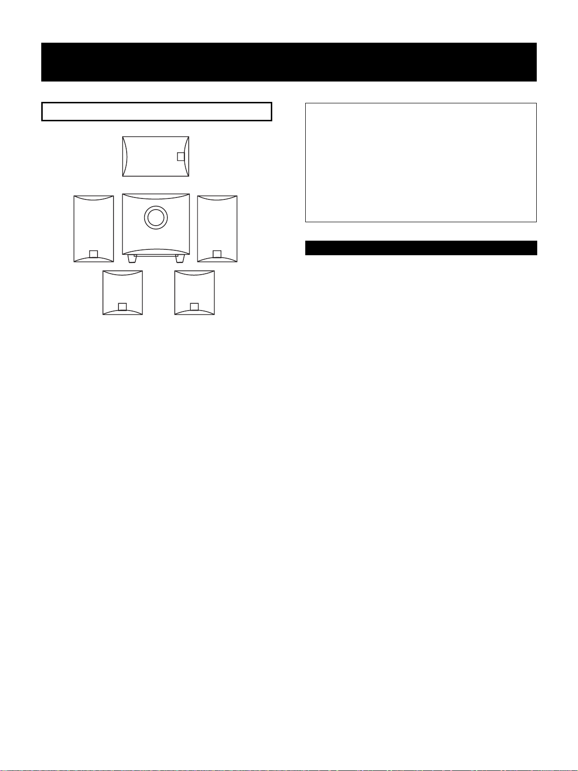
CHECKING ACCESSORIES ...................................................................7
REMOTE CONTROL UNIT.....................................................................7
SPEAKER UNIT ....................................................................................8
INSTALLATION.....................................................................................9
English
2. NAMES AND FUNCTIONS OF PARTS
NAMES OF PARTS
Front Panel ...................................................................................10
Display..........................................................................................11
REMOTE CONTROL UNIT...................................................................12
CONNECTING DEVICES................................................................ 13-15
3. SURROUND
ENJOYING SURROUND EFFECTS
Switching the Dolby Pro Logic and the sound effects
(SFC MODE) ................................................................................16
Switching the sound effects (SFC MODE)....................................17
Enjoying Movie and Music sources in surround mode ................. 18
Setting the Delay Time..................................................................19
*
Manufactured under license from Dolby Laboratories.
“Dolby”, “Pro Logic” and double-D symbol are trademarks of Dolby Laboratories. Confidential Unpublished
Works. © 1992 - 1997 Dolby Laboratories. All rights
reserved.
En
3

CONTENTS
4. OPERATIONS
LISTENING TO FM/AM BROADCASTS................................................20
Directly inputting the frequency....................................................21
Memorizing desired stations ........................................................22
Listening to memorized stations...................................................23
Recording with a VCR...................................................................24
5. OPERA TIONS FOR OTHER EQUIPMENTS
OPERATING OTHER EQUIPMENT USING THIS UNIT’S REMOTE
CONTROL...........................................................................................25
Preset recall set up .......................................................................25
Canceling all preset mode settings ...............................................26
DVD PLAYER operation ................................................................27
LD PLAYER operation...................................................................28
SAT operation...............................................................................28
CD PLAYER/MD PLAYER operation ..............................................29
CASSETTE DECK/VCR operation ..................................................29
TV/CATV operation .......................................................................30
6. OTHER
SURROUND .......................................................................................31
TROUBLESHOOTING..........................................................................33
LIST OF MANUFACTURER CODES .....................................................34
SPECIFICATIONS................................................................................35
4
En
4
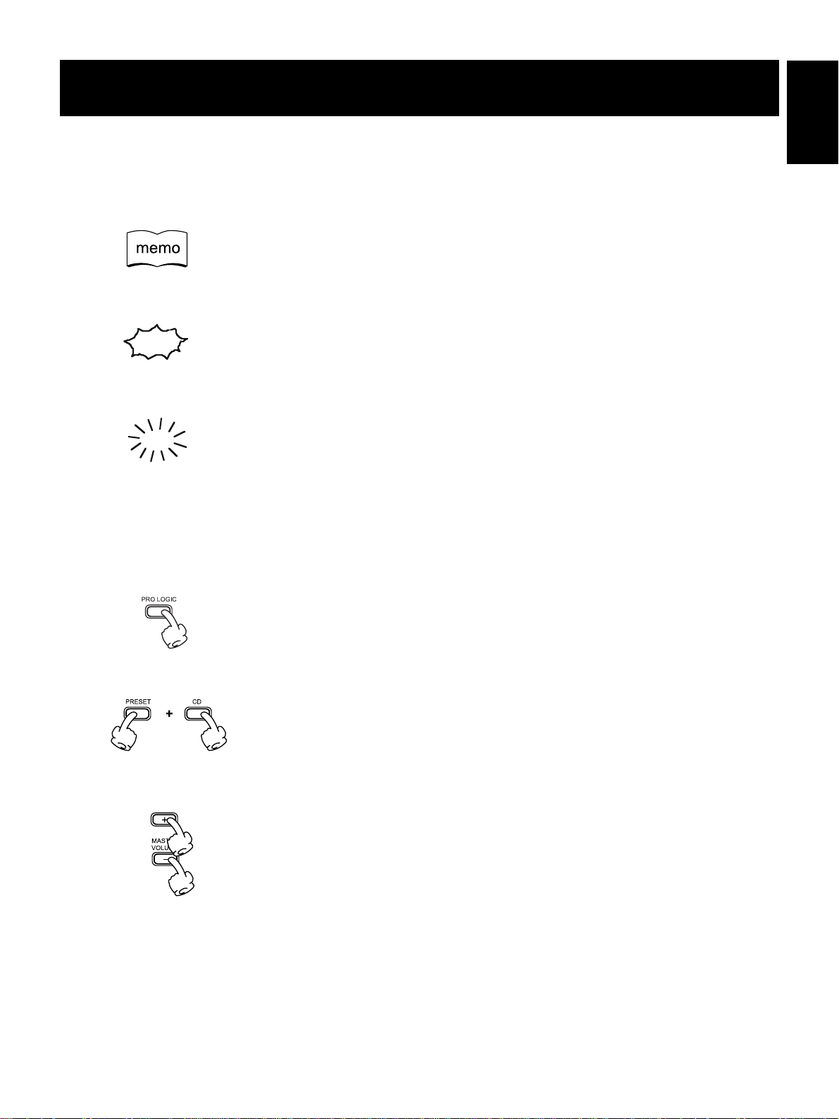
READING THIS MANUAL
77
7 Meaning of Marks
77
Provides detailed precautions and advice on operations, etc.
Indicates that displays are blinking.
Indicates that displays are lit.
English
77
7 Meaning of Illustrations
77
The following describes illustrations on pressing buttons.
Means to press the PRO LOGIC button.
Press the PRESET button and CD button at one time.
Means to press the MASTER VOLUME + or MASTER VOLUME – button (of the remote
control unit.)
En
5
1. BEFORE USE
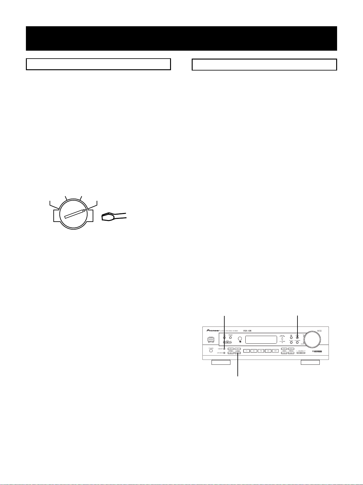
VOLTAGE SELECTOR SWITCH
Mains voltag in Saudi Arabia are 127V and 220V only.
Never use this model with the 110V setting in Saudi
Arabia.
This line voltage selector switch is on the rear panel. Check
that it is set properly before plugging the power cord into
the household wall socket. If the voltage is not properly set
or if you move to an area where the voltage requirements
differ, adjust the selector switch as follows.
1. Use a medium-size screwdriver.
2. Insert the screwdriver into the groove on the voltage
selector, and adjust so that the tip of the arrow points to
the voltage value of your area.
120-127V 110V
VOLTAGE SELECTORS
220V240V
Medium-size screwdriver
CHANNEL STEP SETTING
The unit has been factory preset to the channel allocation
value for the area in which it is to be sold. If this value is set
incorrectly, the tunes in frequency may be wrong, or sound
may be distorted, resulting in an inability to reproduce
reception signals at their proper sound quality. For this
reason, be sure to confirm that the values are set correctly
before first using the unit.
FM 100kHz, AM 10kHz:
Set to this position for areas with an FM reception step of
100kHz and AM 10kHz.
FM 50kHz, AM 9kHz:
Set to this position, for areas with an FM reception step of
50kHz and AM 9kHz.
NOTE:
When unsure about the channel allocation for your area,
consult your dealer for correct information.
To Change Channel Steps
With the power turned on, function is set TV . (Any mode is
available) Hold the MEMORY and TUNING (-) button
pressed while pressing the SFC button to change the display is AMERICA or GENERAL by every time pushing.
AMERICA is FM 100kHz / AM 10kHz and GENERAL is FM
50kHz / AM 9kHz. The display is returned to the TV after 5
seconds.
MEMORY SFC MODE
TUNING -
6
En
6
BEFORE USE
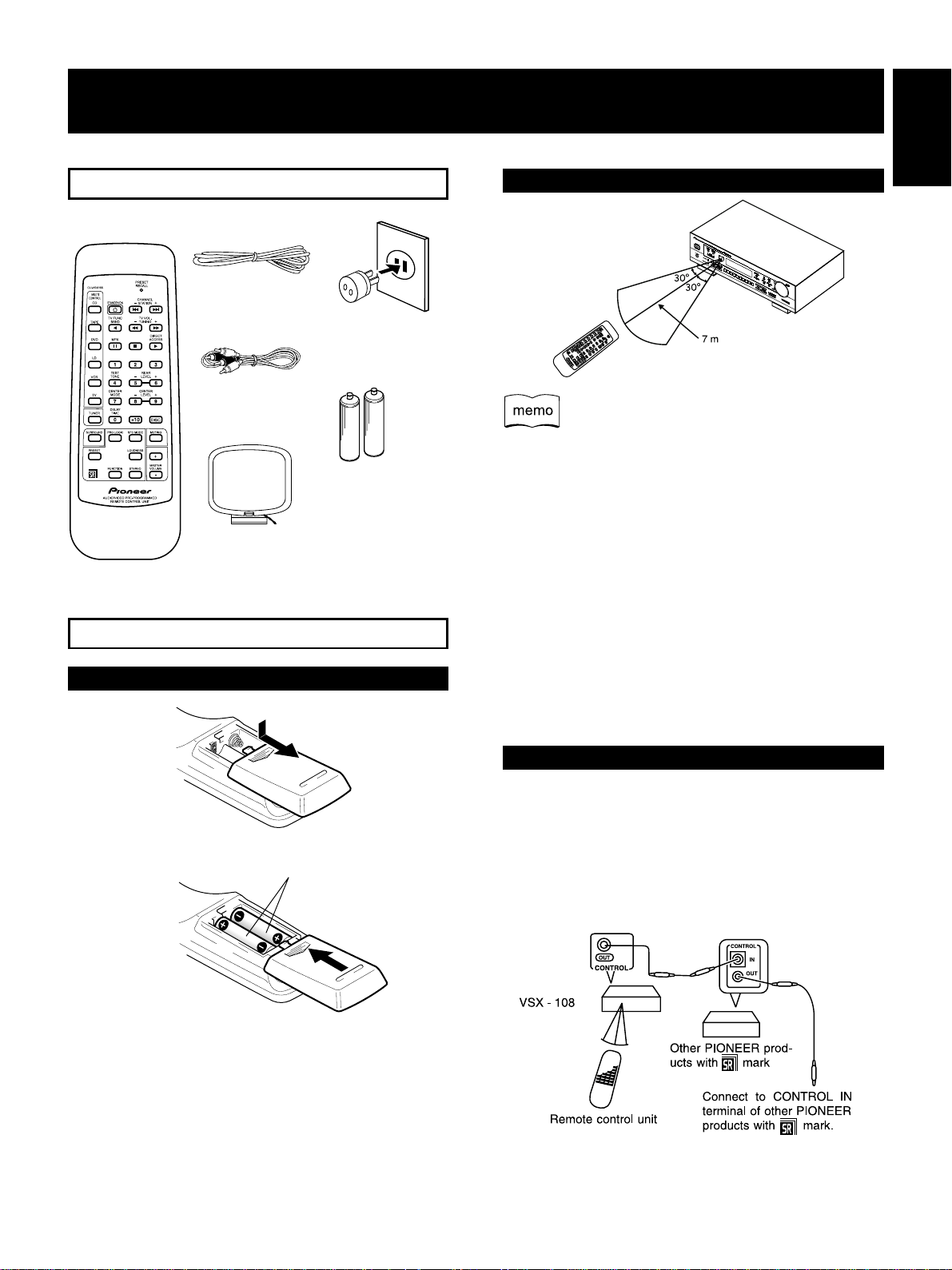
CHECKING ACCESSORIES
FM antenna
RCA Cable
AM loop antenna
Remote control unit
REMOTE CONTROL UNIT
Loading Remote Control Batteries
1
.
AC adaptor Plug
Dry Cell battery
(size “AA” IEC R6P) × 2
Operating Range of Remote Control Unit
English
¶ The remote control unit may not work if there are
obstacles between the remote control unit and this unit,
and if the remote control unit is not directed toward the
remote sensor of the main unit at the correct angle.
¶ The remote control unit may not work properly if strong
light such as direct sunlight and fluorescent light is
shining onto the main unit’s remote sensor.
¶ The remote control unit may not work properly when this
unit is used near devices emitting infrared rays, or when
remote control units of other devices which use infrared
rays are used.
On the other hand, the use of this remote control unit
may cause other devices to work improperly.
¶ When the operating range of this remote control unit
becomes too short, replace the batteries.
Dry cell battery
2 .
(size “AA” IEC R6P) x 2
CAUTIONS
Incorrect use of batteries may result in such hazards as
leakage and bursting. Observe the following precautions.
¶ Never use new and old batteries together.
¶ Insert the plus and minus sides of the batteries properly
according to the marks in the battery case.
¶ Batteries with the same shape may have different volt-
ages. Do not use different batteries together.
Operating the Remote Control Unit
By connecting the control cord (optional), other PIONEER
products can be operated using this remote control unit via
this unit. Direct the remote control unit towards the remote
sensor of this unit.
The remote control signals are received by the remote
sensor of this unit, and sent to the other devices via the
CONTROL OUT terminal.
En
7
BEFORE USE
SPEAKER UNIT
Center Speaker
Front L Speaker
¶ Please read this operating instructions through before
using your speaker system so you will know how to
optimize performance. After you have finished reading
the operating instructions, store it in a safe place for
future reference.
¶ The nominal impedance of these speaker systems are 8
ohms. Connect the speaker system to a stereo amplifier
with a load impedance ranging from 8 to 16 ohms (a
model with “8 Ω-16 Ω” displayed on the speaker output
terminals).
¶ In order to prevent damage to the speaker system
resulting from input overload, please observe the
following precautions:
¶ Do not supply power to the speaker system in excess
of the maximum permissible input.
¶ When connecting or disconnecting pin-plugs, be sure
amplifier power is OFF.
¶ When using a graphic equalizer to emphasize loud
sounds over a high-frequency range, do not use
excessive amplifier volume.
¶ Do not try to force a low-powered amplifier to
produce loud volumes of sound (the amplifier’s
harmonic distortion will be increased, and you may
damage the speaker).
¶ Do not touch the speaker cone’s reverberating surfaces
as they may be damaged by external force.
Subwoofer Speaker
Rear L Speaker Rear R Speaker
Front R Speaker
This Front speaker and Center speaker system is magnetically shielded.
However , depending on the installation location, color distortion may occur if the speaker system is installed extremely close to the screen off a television set.
If this happenscase, turn of the power switch of the television set OFF , and turn it on after 15 to 30 minutes. If the
problem persists, place the speaker system away from
the television set.
CABINET MAINTENANCE
¶ Use a polishing cloth or dry cloth to wipe off dust and
dirt.
¶ When the cabinet is very dirty, clean with s soft cloth
dipped in some neutral cleanser diluted five or six times
with water, and then wipe again with a dry cloth. Do not
use furniture wax or cleaners.
¶ Never use thinners, benzine, insecticide sprays and other
chemicals on or near the cabinets, since these will
corrode the surfaces.
8
En
8
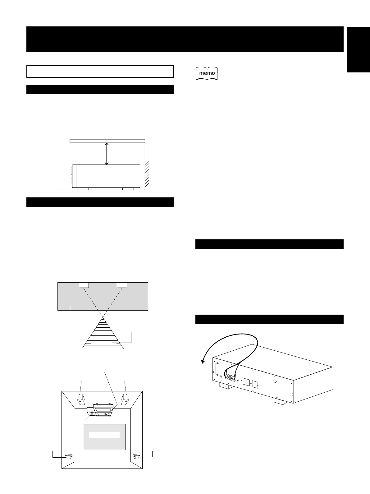
INSTALLATION
Installing this Unit
Do not place objects on top of this unit so that radiated heat
can be properly dispersed.
When installing in racks, etc., leave more than 20 cm of
space at the top.
Leave more than 20 cm
Installing Speakers
The subwoofer plays back the bass in monaural, making use
of the fact that the human ear loses the sense of direction of
low-pitched sound. Since the sense of direction is lost, the
subwoofer can be installed almost anywhere. If it is
installed too far away, however, the sound from the left and
right speakers may become unnatural.
¶ Subwoofer Installation Criteria
Front left speaker
Front right speaker
BEFORE USE
Position the left and right channel speakers at equal
distances from the TV set and approximately 1.8 meters
from each other.
Install the center speaker above or below the TV so that
the sound of the center channel is localized at the TV
screen.
The rear (surround) speakers are most effective when
installed in parallel locations directly to the side, or
slightly behind, the listener, at a level about 1 meter
above the listener’s ears.
Cautions regarding installation
¶ Do not install this speaker system near a stove or other
heating appliance, or put it in a place exposed to the sun.
Such locations may cause the cabinet to change color
and the speaker system to break down.
¶ Remeber that this speaker system is quite heavy, so it is
dangerous to install it in a high place such as on a wall or
pillar or in other unstable locations.
Installing the VCR Deck
The VCR deck may produce noise when played back
depending on the place of installation.
The noise is due to the effects of leakage flux caused by the
transformer of the receiver.
In such cases, change the place of installation or install it
away from the receiver.
English
Recommended installation
range for the subwoofer
Listening position
¶ An example of speaker positioning
Center speaker
Front left speaker
Subwoofer
Listening area
Rear left speaker
Front right speaker
Rear right speaker
Styling the connected cable
Leaving cables in a loop on the unit as shown in the figure
above may cause humming noise due to leakage of the transformer to be heard from the speakers. Avoid such layout of
the cables.
9
En
2. NAMES AND FUNCTIONS OF PARTS
NAMES OF PARTS
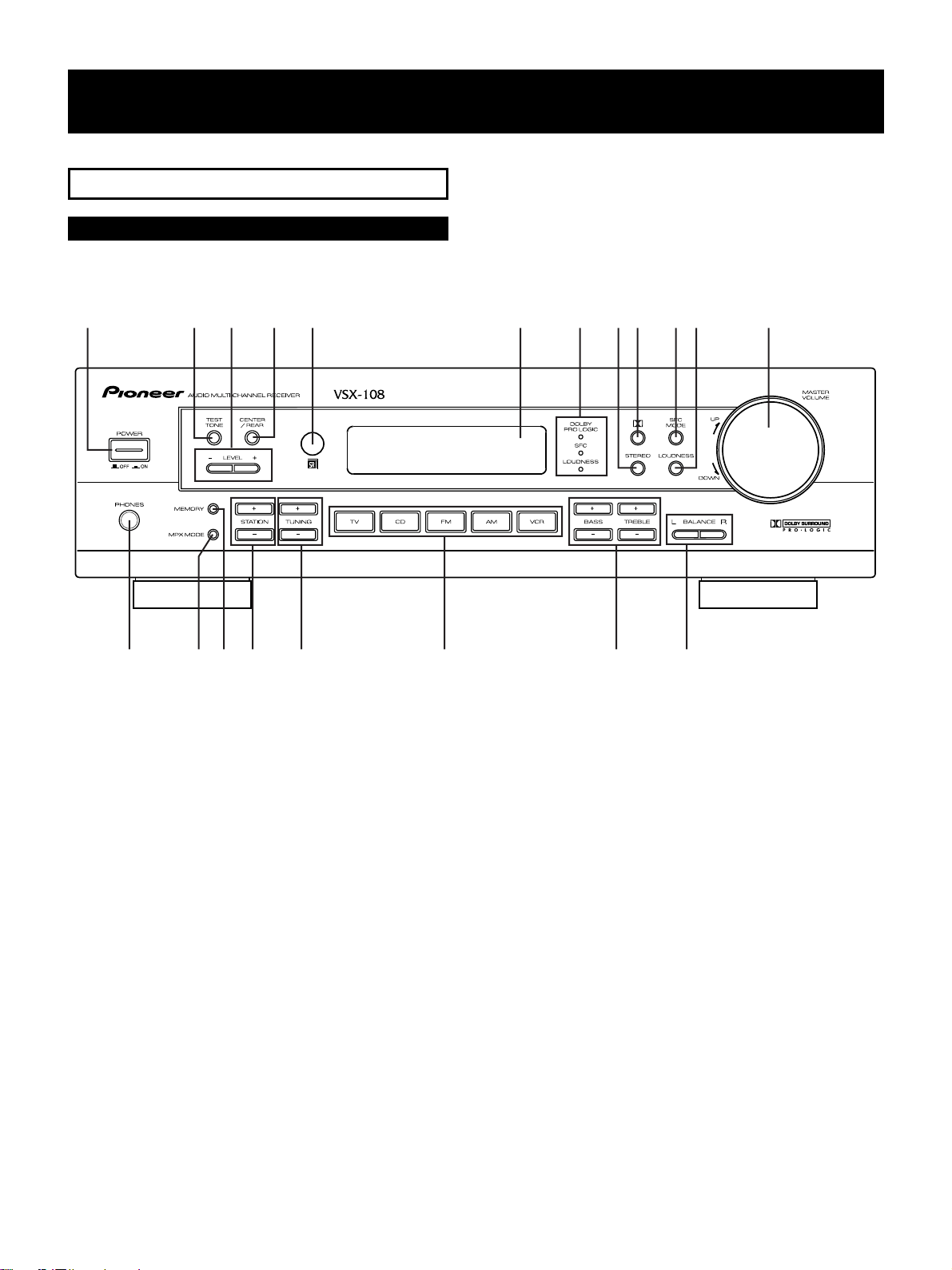
Front Panel
The size of characters in the figure may different from that
on the actual product.
1 23 45 6 7890- =
~!
@# $ % ^ &
1 POWER ON/OFF button
2 TEST TONE ON/OFF button
The TEST TONE signal will be output in the Dolby Pro
logic mode.
3 LEVEL button
Use to adjust center or rear level
4 CENTER/REAR button
Use to select the Level Control.
5 REMOTE SENSOR
6 DISPLAY
7 LED INDICATOR
“DOLBY PRO LOGIC”, SFC, LOUDNESS
8 STEREO button
Use to playback sound that DOLBY PRO LOGIC and SFC
MODE turn off.
9 DOLBY PRO LOGIC button (P.16,18-19)
0 SFC MODE button (P.17)
- LOUDNESS button
Press this button when the volume is low to raise the
low and high range levels so that the sound can be
heard more easily.
= MASTER VOLUME
~ PHONES JACK (Headphone terminal)
! MPX MODE button
Use to switch the auto stereo/monaural mode for
receiving FM broadcasts. In case of “STEREO”
indicator does not turn on because broadcast signal is
too weak, sound is monaural automatically.
@ MEMORY button
# STATION (+, -) button
Use to select the station number when operating the
tuner.
$ TUNING (+, -) button
Use to select the frequency when operating the tuner.
% FUNCTION buttons
^ TONE [BASS (+, -), TREBLE (+,-)] LEVEL button
Use to adjust tone level.
& BALANCE (L, R) button
Use to adjust volume balance.
10
En
NAMES AND FUNCTIONS OF PARTS
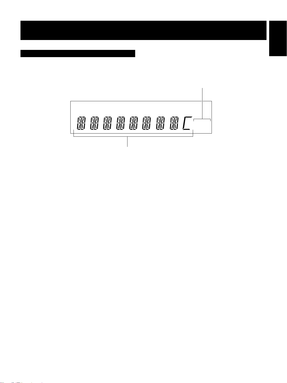
Display
A DIRECT LOUDNESS PRO LOGIC VIRTUAL DSP TAPE 2
SP
TUNER indicator
1
MONO:
Lights when the monaural mode is set using the MPX
MODE button.
TUNED:
Lights when broadcasts are being received.
STEREO:
Lights when stereo broadcasts are received during auto
stereo mode.
English
1
MONO
TUNED
STEREO
2
2 CHARACTER display
11
En
NAMES AND FUNCTIONS OF PARTS
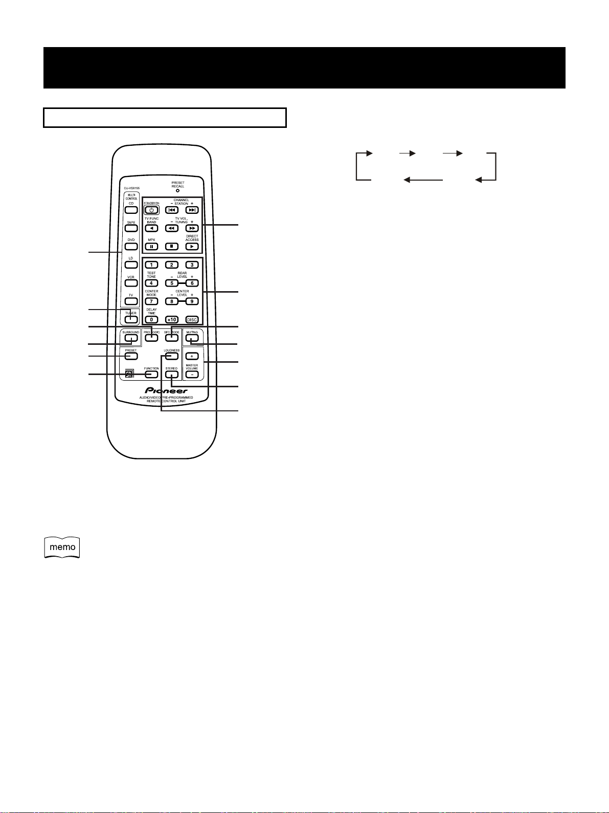
REMOTE CONTROL UNIT
7
1
8
2
3
4
5
6
1 MULTI CONTROL function buttons
When operating other devices, press any one of these
buttons to specify the device to be operated.
This button cannot be used to switch the functions of this
unit.
2 TUNER button (P.20)
Press to operate this unit when set to the TUNER.
3 PRO LOGIC button (P.16)
Use to change the mode of DOLBY PRO LOGIC.
4 SURROUND button (P.18)
Press to start the SURROUND function.
5 PRESET button (P.25)
To preset other brand devices, press any one of the
MULTI CONTROL function buttons together with this
button.
9
0
-
=
~
6 FUNCTION button (P.20)
Use to switch the function setting of this unit.
TV
CD FM
VCR AM
7 [TUNER operations]
STATION -, +, BAND, TUNING -, +, MPX, D.ACCESS
buttons.
[TV operations]
STANDBY/ON, CHANNEL -, +, TV FUNC., TV VOL. -, +,
buttons
[CD, TAPE, DVD, LD, VCR, MD operations]
STANDBY/ON, 4, ¢ (Chapter / Track search),
2 (Play), 1 (Rewind), ¡ (Fast Forward),
8(Pause), 7(Stop), 3(Play)
8 Number/Surround setting buttons
TEST TONE: When turned ON (while in DOLBY PRO
LOGIC), volume balance adjustment signals are out put
in order from the speakers and can adjusted.
REAR LEVEL -, +: Adjusts the rear level.
CENTER MODE: Switches the center mode.
CENTER LEVEL -, +: Adjusts the center level.
DELAY TIME: Use to set the delay time.
9 SFC MODE button (P.17)
Use to switch the SFC mode.
0 MUTING button
Press to mute the volume.
- MASTER VOLUME -/+ button
Use to adjust the volume.
= STEREO button
Use to playback sound without DOLBY PRO LOGIC and
SFC MODE.
~ LOUDNESS button
When LOUDNESS is turned ON at a small volume, the
low frequency and high frequency levels increase,
enabling the sound to be easier to hear.
12
En
NAMES AND FUNCTIONS OF PARTS
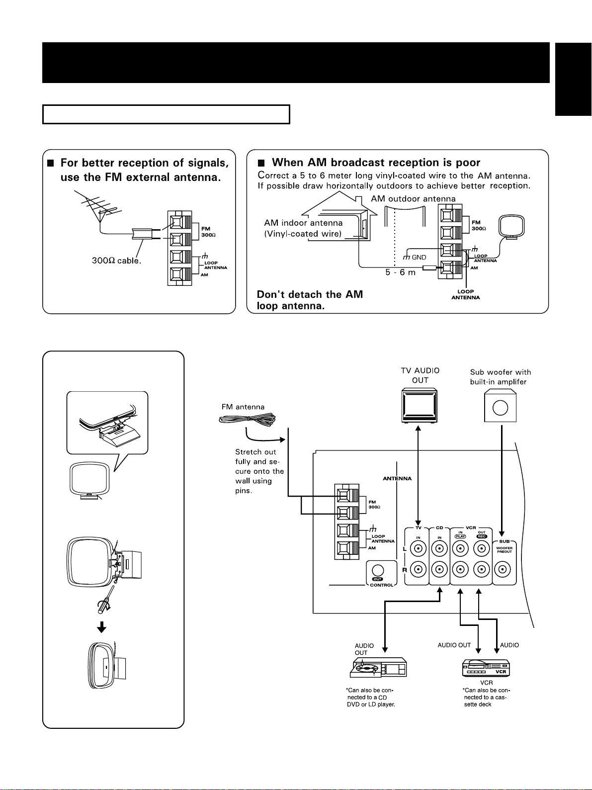
CONNECTING DEVICES
77
7
Assembling the AM loop
77
antenna
When connecting or changing equipment, be sure to turn
OFF the POWER switch, and disconnect the power cord
from the wall outlet.
English
77
7
When attached on a
77
wall, etc.
Face towards the direction
with the best reception
IN
,
13
En
NAMES AND FUNCTIONS OF PARTS
77
7
Antenna terminal
77
77
7
Input/output plug
77
○○○○○○○○○○○○○
77
7
77
L
10 mm
R
1
2
3
Connect the white plug to L and red plug to R. Be sure to
insert completely.
The size of characters and terminal positions in the figures may differ from those on the actual product.
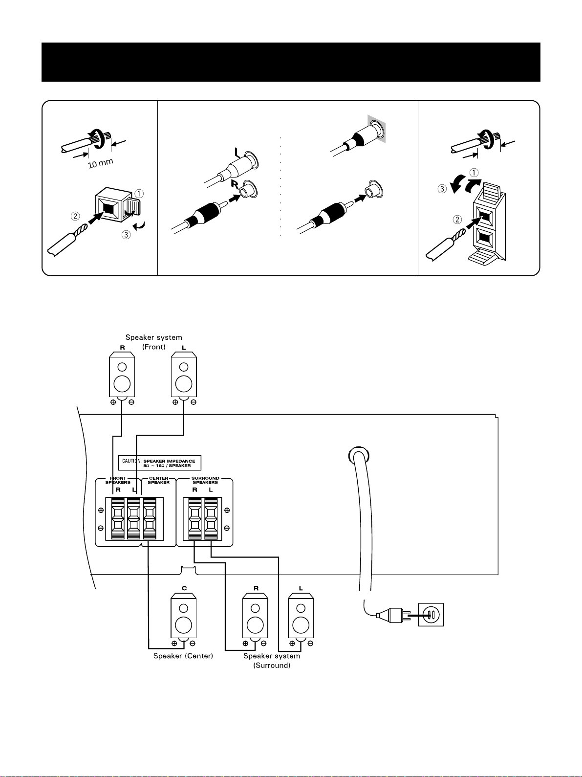
Speakers terminal
10 mm
1
3
2
ª
·
14
En
NAMES AND FUNCTIONS OF PARTS
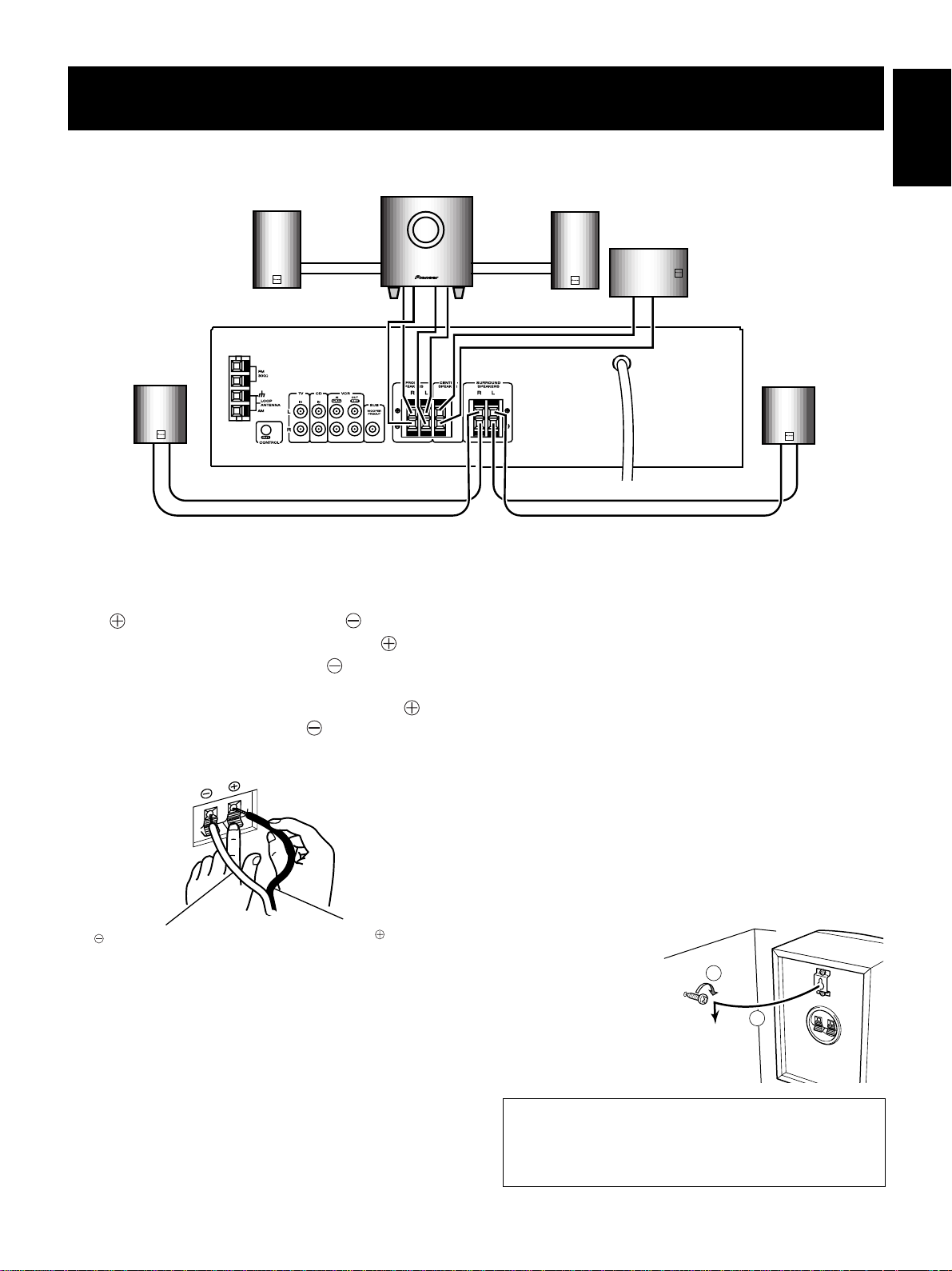
When use packed speaker system
Front right speaker
OUTPUT
–
+
pink line
Rear right speaker
+
orange line
–
INPUT
red line
Subwoofer
–+–
CONNECTIONS
1. Set the amplifier’s power switch to OFF.
2. Connect the speaker cords to the input terminals at the
rear of the speaker system; connect the colored cord to
the terminal and the white cord to the terminal.
Bear in mind that the red input terminal has a “ ”
polarity, and the other terminal has a “ ” polarity.
3. Connect the speaker cords to the amplifier’s speaker
output terminals. Connect the colored cord to the
terminal and the white cord to the terminal.
Presione la palanca del terminal de entrada e inserte la punta
del cable en el orificio, y luego suelte la palanca de modo que
retorne con efecto de resorte a su posición original.
OUTPUT
light blue line
INPUT
+
dark blue line
WHEN THE SPEAKER SYSTEM IS
MOUNTED ON A WALL (Except for
Subwoofer)
¶ Before fitting the satellite speakers, examine the walls to
¶ This system is not provided with nuts and screws for
¶ If you are unsure of the qualities and strength of the
¶ Pioneer will not be responsible for any accidents or
¶ If fitted on a slanted wall, it may become loose and
Front left speaker
Center speaker
–
+
+
yellow line
–
Rear left speaker
+
–
green line
confirm that their strength is sufficient to bear the weight
of the speaker system.
installation, so select suitable ones corresponding to the
qualities of your walls.
walls, consult a professional for advice.
damage that result from improper installation.
present an accident risk.
English
Connect the white cord
teminal.
to the
Connect the colored cord
to the
teminal.
NOTES:
Make sure that the speaker cords are connected to the
terminals securely. Insecure connections may cause not
only sound to be interrupted and noise to be generated
but also the cords to be shorted and the amplifier to
break down.
If listening to a stereo performance with the speaker
system connected to a stereo amplifier and you find that the
bass is insufficient, the sound is not spread out and there is no
stereo effect; the cords of one of the speaker systems have
been plugged into the wrong polarity terminals.
When test tone signal is set to Lch, Cch or Rch,
Subwoofer out has test tone sound.
1. Screw the screws into the wall.
2. Attach the speaker
to the wall so that
the heads of the
Wall
1
screws enter the
holes in the back of
2
the speaker, and then
push the speaker
downward to secure it.
PIONEER disclaims all
responsibility for damages that are caused by improper
connection, installation, inappropriate strength of the
wall, improper use and natural calamities etc.
15
En
3. SURROUND
ENJOYING SURROUND EFFECTS
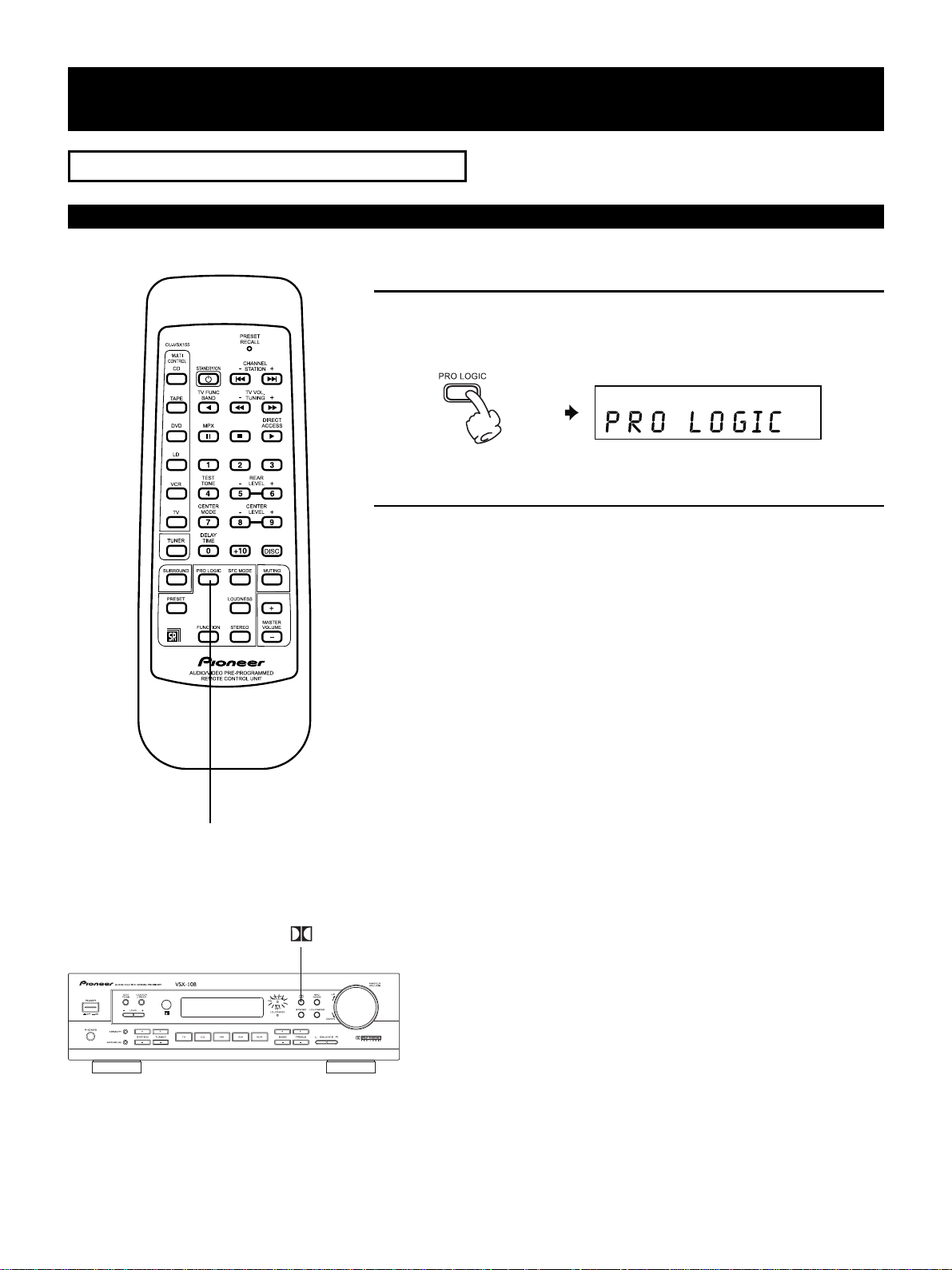
Switching the Dolby Pro Logic and the sound effects (SFC MODE)
Select Dolby Pro Logic
16
En
PRO LOGIC
77
7 Operating with the main unit
77
Press the DOLBY PRO LOGIC button.
SURROUND
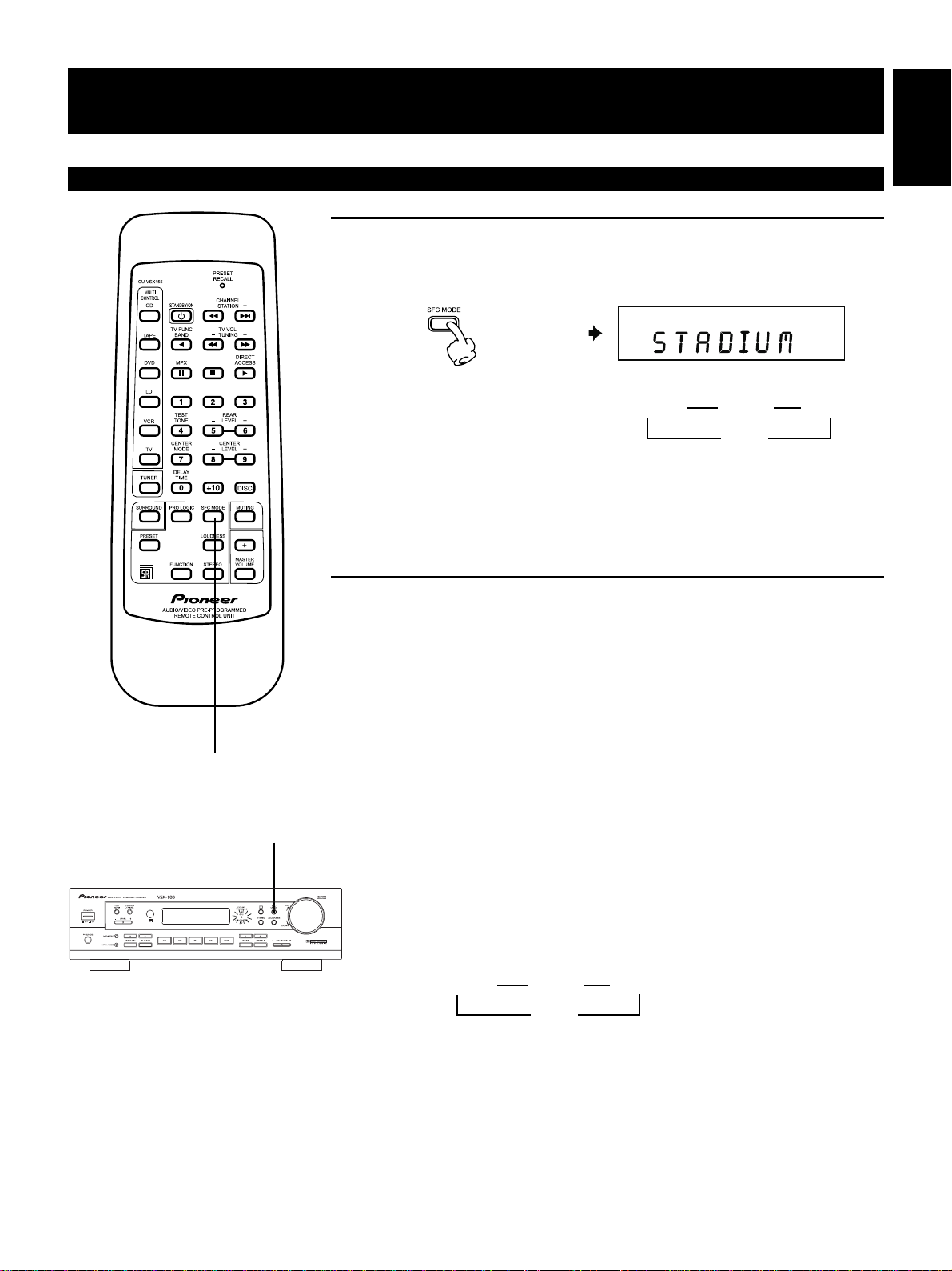
Switching the sound effects (SFC MODE)
Select the sound effects.
Refer to page 32 for the
characteristics of the
surround effects.
STADIUM
5
3
STAGE
LIVE
2
3
English
DISCO
SFC MODE
SFC MODE
77
7 Operating with the main unit
77
Press the SFC MODE button.
Each time it is pressed, the surround effects change as follows.
STADIUM
5
3
STAGE
LIVE
2
3
DISCO
17
En
SURROUND
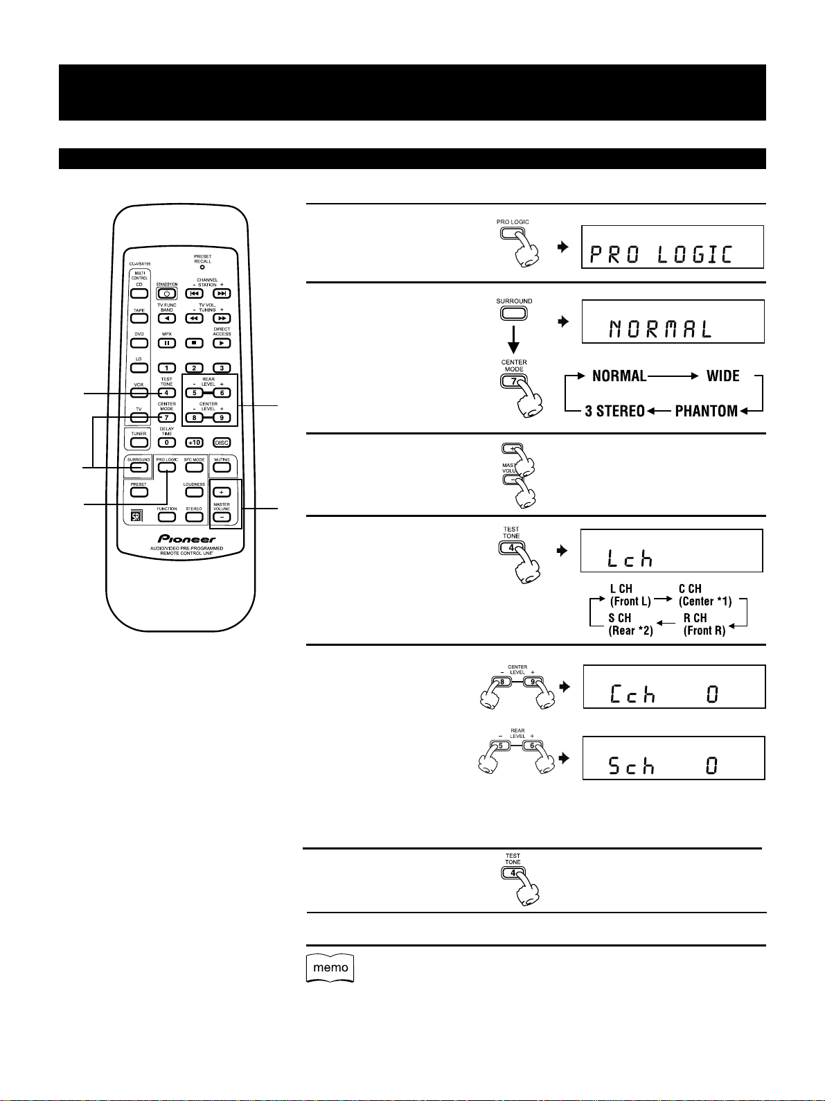
Enjoying Movie and Music sources in surround mode
1.
Select Dolby Pro
Logic.
2.
Select the center
mode.
Before operating,
press the SURROUND button.
4
6
2
5
Refer to page 31 for the
characteristics of the
center modes.
3.
Adjust to the desired
volume.
1
*1.When selecting PHANTOM output from each
in the center mode, no test speaker is the same.
tone is output from the center The BALANCE L, R
speaker. buttons of this unit can
*2.When 3 STEREO is selected FRONT balance.
in the center mode, no test
tone from the surround speaker 6. Tune OFF the test
is output. tone.
3
4.
Set the test tone.
5.
While center or rear
sound is coming out,
adjust the center level
and rear level so that
the test tone volume
be used to adjust the
18
En
7.
Play the desired source.
¶ The TEST TONE signal will be output in the PRO LOGIC mode.
¶ The TEST TONE signal will not be output in the SFC mode, but the only rear level
can be adjusted.
SURROUND
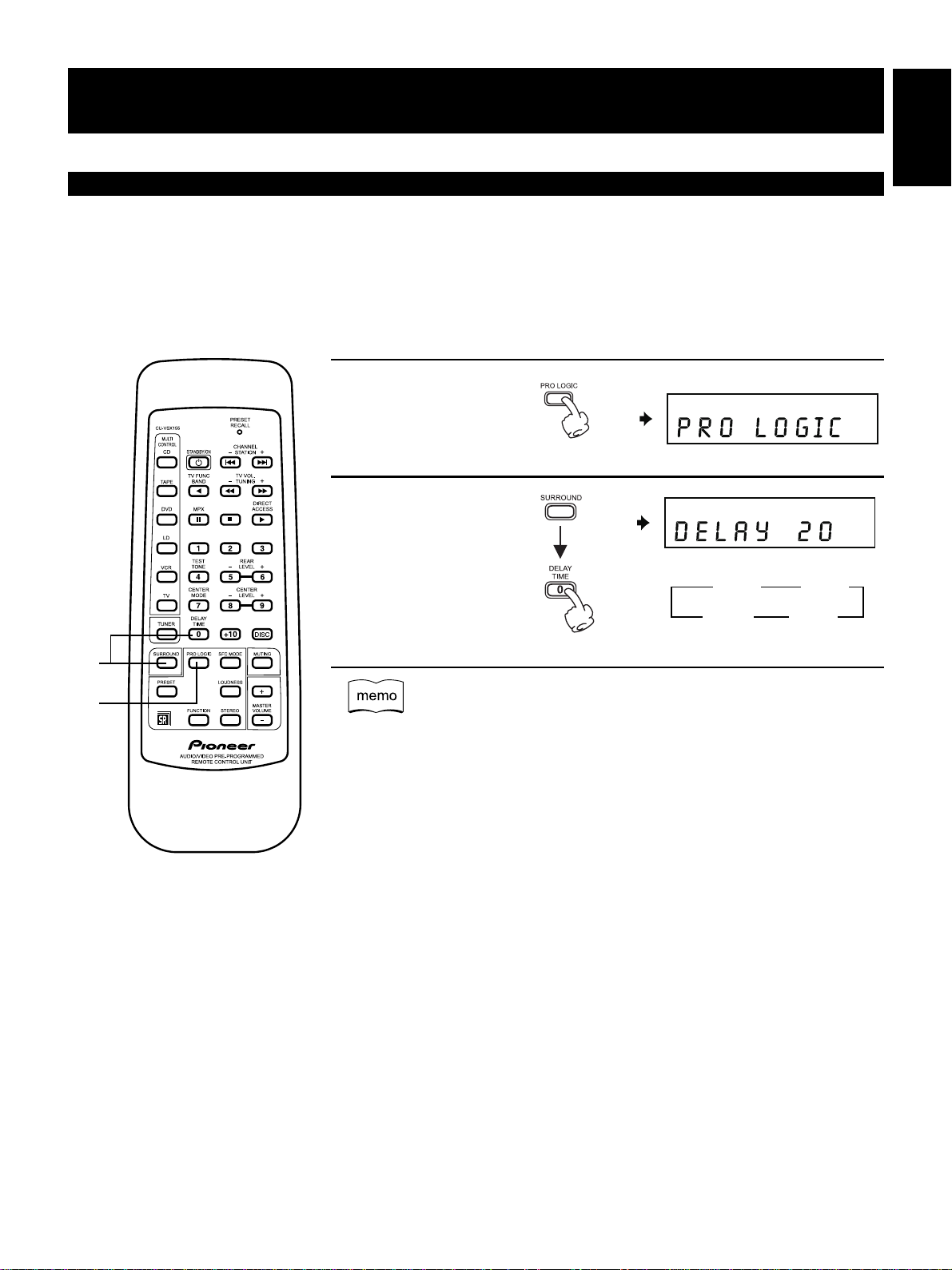
Setting the Delay Time
As the SURROUND speaker is normally placed near the listening position, it is nearer to the listening position than the FRONT
speaker. Subsequently, since the sounds from the SURROUND speaker will be heard quicker than those from the FRONT
speaker, set the delay time for the sounds from the SURROUND speaker so that the SURROUND and FRONT speakers are
virtually the same distance from the listening position.
(Set about 1 to 1.5m for each step.)
1.
Select DOLBY PRO
LOGIC
2.
Set the delay time
English
2
1
2
3
20 ms
25 ms
2
3
15 ms
30 ms
¶ First set to 20 ms.
¶ Initially the distance from the listening position to the SURROUND speaker will be
set shorter than that from to the FRONT speaker.
¶ The delay time is valid during DOLBY PRO LOGIC.
¶ When 3 STEREO is selected in the center mode, the delay time cannot be set.
19
En
4. OPERATIONS
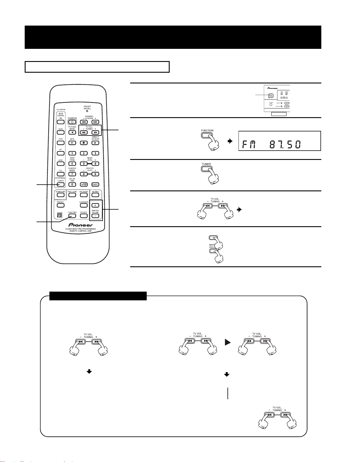
LISTENING TO FM/AM BROADCASTS
1.
Turn ON the powerof
the receiver.
4
2.
Set the FM or AM
function.
3.
Select the TUNER
operations.
3
4.
Select the broadcast Refer to “Selecting broadcast
5
station. station” below.
1
2
5.
Adjust the volume.
Selecting broadcast stations
(For example, when selecting an FM broadcast)
1. Selecting step by step. 2. Selecting automatically.
Press lightly and release. (Press and hold for approx.
over 2 second, then release)
87.50
87.50
87.60
87.70
•
•
•
Stop when received
or pressed again
3
89.50
20
En
OPERATIONS
77
7 Selecting a broadcast station using the main unit
77
14
3
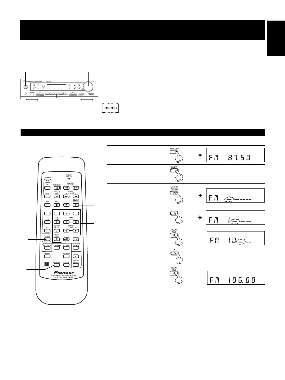
Directly inputting the frequency [Direct Access (remote control unit only)]
2
1. Press the POWER ON/OFF button.
2. Press the FM or AM button and select an FM or AM broadcast.
3. Press the TUNING -, + button and select the broadcast station.
The TUNED indicator lights when broadcast is received. Refer to “Selecting
broadcast station” .
4. Adjust the volume.
The TUNED indicator will not light when a broadcast station is too far away
or when the broadcasting signal is weak.
1.
Set the FM or AM
function.
2.
Select the TUNER
operations.
English
1
2
3.
Set the direct access mode.
3
4.
Select the broad-
4
cast station.
Press the numbers
of the frequency to
be received in order.
77
7 Canceling Direct Access
77
Direct Access can be canceled by pressing the D.ACCESS button again.
21
En
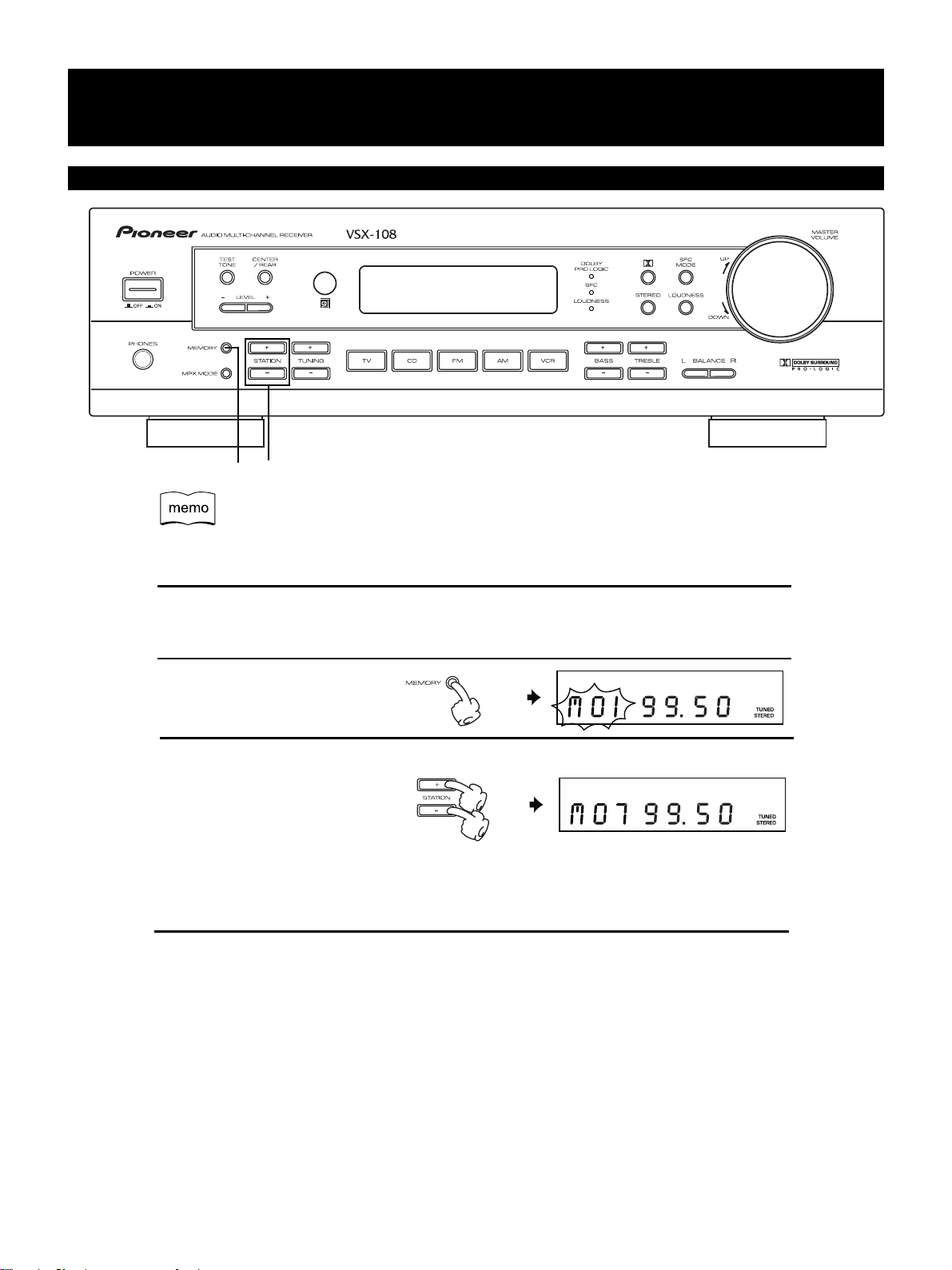
OPERATIONS
Memorizing Desired Stations (Main unit only)
32
¶ The frequency received can be memorized.
¶ Up to 30 stations can be memorized in lamdomly FM or AM.
1.
Receive the desired station. Refer to “LISTENING TO FM/AM
BROADCASTS”
2.
Set the MEMORY mode.
3.
Select the desired station
number.
The selection will be memorized in the specified station number 5 seconds later.
Pressing the MEMORY button within 5 seconds will exit the MEMORY mode.
Repeat steps 1 to 3 to memorize up to 30 stations.
(P.20, 21)
22
En
 Loading...