

Page 1

Service
HTP105/205-SW
Manual
POWERED SUBWOOFER
ORDER NO.
PET99019
HTP105/205-SW
CONTENTS
1. SAFETY INFORMATION ............................................. 2
2. DISASSEMBLY ............................................................ 3
3. PACKING, EXPLODED VIEWS AND PARTS LIST ..... 3
4. SCHEMATIC AND PCB CONNECTION DIAGRAMS.. 6
5. PCB PARTS LIST ........................................................ 8
6. PANEL FACILITIES...................................................... 9
7. SPECIFICATIONS ....................................................... 10
PIONEER CORPORATION 4-1, Meguro 1-Chome, Meguro-ku, Tokyo 153-8655, Japan
PIONEER ELECTRONICS SERVICE, INC. P.O.Box 1760, Long Beach, CA 90801-1760, U.S.A.
© PIONEER CORPORATION 1999
1
Page 2
HTP105/205-SW
1. SAFETY INFORMATION
This service manual is intended for qualified service technicians; it is not meant for the casual do-ityourselfer. Qualified technicians have the necessary test equipment and tools, and have been trained to
properly and safely repair complex products such as those covered by this manual.
Improperly preformed repairs can adversely affect the safety and reliability of the product and may void
the warranty. If you are not a qualified to perform the repair of this product properly and safely, you
should not risk trying to do so and refer the repair to a qualified service technician.
WARNING
Lead in solder used in this product is listed by the California Health and Welfare agency as a known reproductive
toxicant which may cause birth defects or other reproductive harm (California Health & Safety Code, Section
25249.5). When servicing or handling circuit boards and other components which contain lead in solder, avoid
unprotected skin contact with the solder. Also, when soldering do not inhale any smoke or fumes produced.
NOTICE
(FOR CANADIAN MODEL ONLY)
Fuse symbols (fast operating fuse) and/or (slow operating fuse) on PCB indicate that replacement
parts must be of identical designation.
REMARQUE
(POUR MODÈLE CANADIEN SEULEMENT)
Les symboles de fusible (fusible de type rapide) et/ou (fusible de type lent) sur CCI indiquent que
les pièces de remplacement doivent avoir la même désignation.
(FOR USA MODEL ONLY)
1. SAFETY PRECAUTIONS
The following check should be performed for the
continued protection of the customer and service
technician.
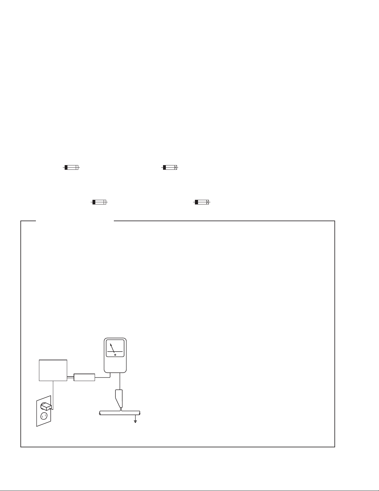
LEAKAGE CURRENT CHECK
Measure leakage current to a know earth ground
(water pipe, conduit, etc.) by connecting a leakage
current tester such as Simpson Model 229-2 or
equivalent between the earth ground and all exposed
metal parts of the appliance (input/output terminals,
screwheads, metal overlays, control shaft, etc.). Plug
the AC line cord of the appliance directly into a 120V
AC 60Hz outlet and turn the AC power switch on. Any
current measured must no exceed 0.5mA.
Reading should
not be above
Device
under
test
Test all
exposed metal
surfaces
Leakage
current
tester
+
0.5mA
-
ANY MEASUREMENT NOT WITHIN THE LIMITS
OUTLINED ABOVE ARE INDICATIVE OF A
POTENTIAL SHOCK HAZARD AND MUST BE
CORRECTED BEFORE RERTURNING THE
APPLIANCE TO THE CUSTOMER.
2. PRODUCT SAFETY NOTICE
Many electrical and mechanical parts in the appliance
have special safety related characteristic. These are
often not evident from visual inspection nor the
protection afforded by them necessarily can be
obtained by using replacement components rated for
voltage, wattage, etc. Replacement parts which have
these special safety characteristics are identified in this
Service Manual.
Electrical components having such features are
identified by marking with a D on the schematics and
on the parts list in this Service Manual.
The use of a substitute replacement component which
dose not have the same safety characteristics as the
PIONEER recommended replacement one, shown in
the parts list in this Service Manual, may create sock,
fire, or other hazards.
Also test with
plug reversed
(Using AC adapter
plug as required)
AC Leakage Test
Earth
ground
instructions are issued from time to time. For the latest
information, always consult the current PIONEER
Service Manual. A subscription to, or additional copies
of, PIONEER Service Manual may be obtained at a
nominal charge from PIONEER.
2
Product Safety is continuously under review and new
Page 3

2. DISASSEMBLY
HTP105/205-SW
●
POWER AMP SECTION
• Remove the 8 screws from the power amplifier.
• Remove the connector lead, etc.
●
GRILLE SECTION
• The grill is attached to the cabinet by its bosses applied
with adhesive. To detach it, pry it open by inserting a flat
blade scewdriver between the cabinet and the grille.
●
SPEAKER
• Remove each of the 4 screws
3. PACKING, EXPLODED VIEWS AND PARTS LIST
NOTES:
●
Parts marked by "NSP" are generally unavailable because they are not in our Master Spare Parts List.
●
The mark found on some component parts indicates the importance of the safety factor of the part. Therefore, when replacing, be sure to use
parts of identical designation.
●
Parts marked by " " are not always kept in stock. Their delivery time may be longer than usual or they may be unavailable.
3.1 PACKING
Parts List
Mark No. Description Parts No.
Operating Instructions 268206
RCA Cable Accessory Pack 255245
Corner Pad Assy 264333
Poly Bag 266953
Packing Case 264328
3
Page 4
HTP105/205-SW
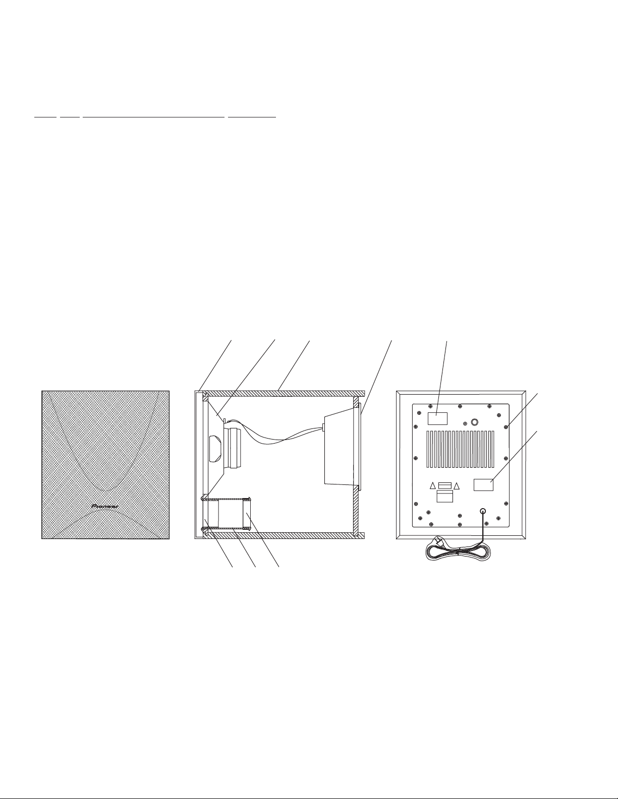
3.2 EXTERIOR SECTION
Parts List
Mark No. Description Parts No.
NSP 1 Cabinet Enclosure 264388
NSP 2 Amplifier Assembly 264462
NSP 4 Paper Port Tube 256946
NSP 5 Front Port Ring 254306
NSP 6 Rear Port Ring 254346
NSP 7 Label FTC Sticker 268182
NSP 8 UL-CUL Label 268197
3 Grille Assembly 264353
9 Transducer 264719
10 Screw (for Amplifier and Trans) 221904
3
456
9
1
2
8
10
7
4
Page 5

3.3 POWER AMP SECTION
4
1
2
3
15
8
11
10
9
12
13
14
5
13
12
12
12
7
12
6
Parts List
http://getMANUAL.com
HTP105/205-SW
Mark No. Description Parts No.
1 2P Cord 044899
2 AC Cord 046947
3 BRKT PCB C 077876
NSP Cushion Gasket 078786
4 Cushion Stopper 078519
5 Trans Power 046946
6 Trans Back Up 047073
7 Heatsink Sub 045576
8 Knob 072992
Cable Tie 080558
9 Mold Case 080336
Mark No. Description Parts No.
10 Panel Rear Assy 046981
NSP 11 Power Amp PCB Section 047259
12 Screw (3X10 BL) 075640
13 Screw (4X10 BL) 075659
14 Screw (M3X8 ZC) 075273
15 Heatsink 046971
16 Tr 2SC4008 (Q610, Q614) 084682
5
Page 6
HTP105/205-SW
4. SCHEMATIC AND PCB CONNTCTION DIAGRAMS
NOTE FOR SCHEMATIC DIAGRAMS (Type 1A)
1. When ordering service parts, be sure to refer to
"PARTS LIST of EXPLODED VIEWS" or "PCB
PARTS LIST".
2. Since these are basic circuits, some parts of them or the
values of some components may be changed for improvement.
3. RESISTORS:
Unit: k:kΩ, M:MΩ, or Ω unless otherwise noted.
Rated power: 1/4W, 1/6W, 1/8W, 1/10W unless otherwise
noted.
Tolerance: (F): ±1%, (G): ±2%, (K): ±10%, (M): ±20% or ±5% un-
less otherwise noted.
4. CAPACITORS:
Unit: p:pF or µF unless otherwise noted.
Ratings: capacitor (µF)/voltage(V) unless othrewise noted.
Rated voltage: 50V except for electrolytic capacitors.
5. COILS:
Unit: m:mH or µH unless otherwise noted.
6. VOLTAGE AND CURRENT:
mA or ← mA:
7. OTHERS:
8. SCH-
9. SWITCHES (Underline indicates switch position):
: Signal voltage at rated output.
V
or ← V:
DC voltage (V) at no input signal unless otherwise noted.
Value in ( ) is DC voltage at rated power.
DC current at no input signal unless otherwise noted.
• or : Adjusting point.
• : Measurement point.
• The mark found on some component parts indicates the im-
portance of the safety factor of the parts. Therefore, when replacing, be sure to use parts of identical designation.
& ON THE SCHEMATIC DIAGRAM:
& indicates the drawing number of the schematic dia
• SCH-
gram. (SCH stands for schematic diagram.)
• MAIN + CONT. ASSY
S501 : PHASE Rev / Norm
S502 : AUTO POWER ON/OFF
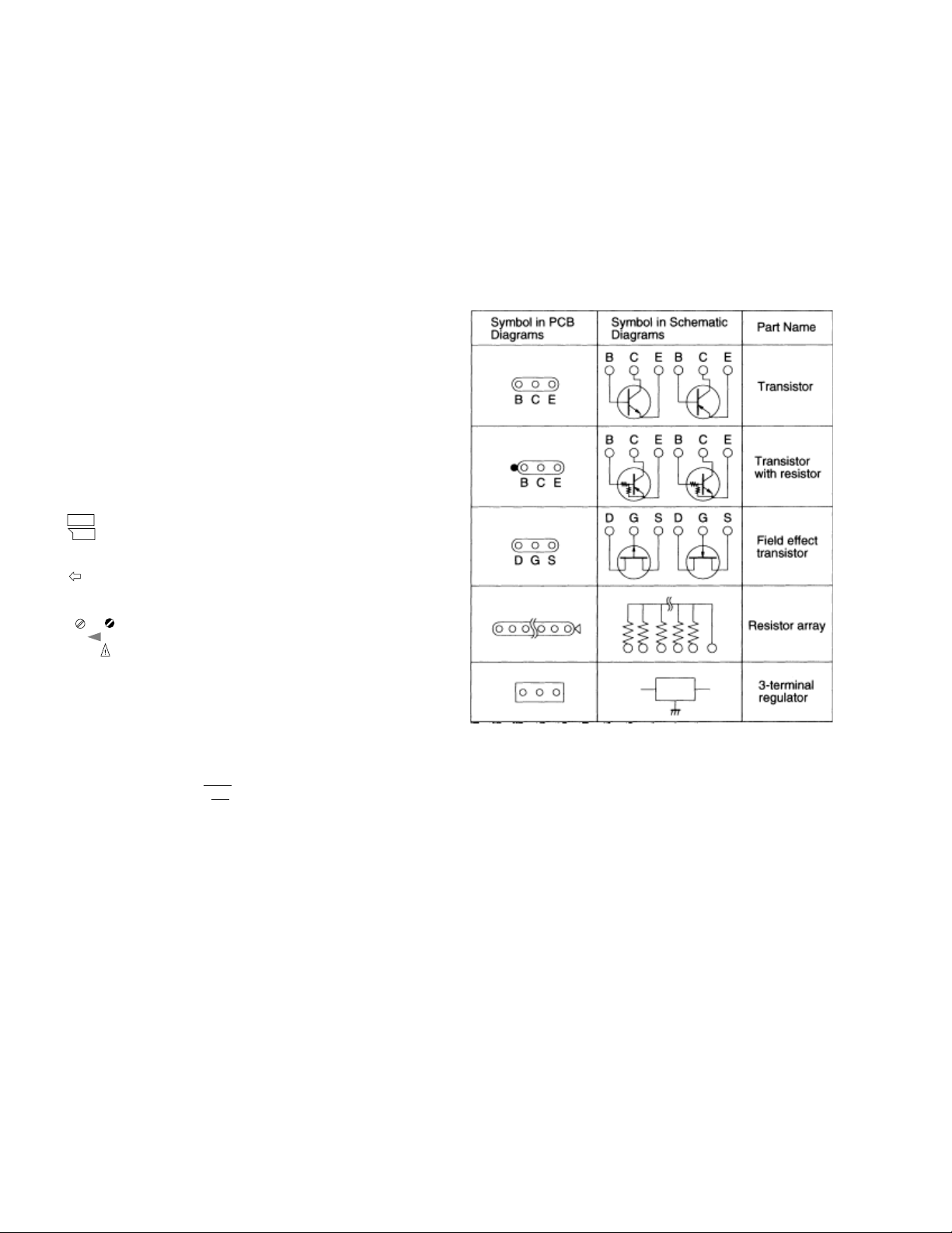
NOTE FOR PCB DIAGRAMS
1. Partnumbers in PCB diagrams match those in the schematic
diagrams.
2. A comparison between the main parts of PCB and schematic
diagrams is shown below.
6
Page 7

HTP105/205-SW
4.1 CIRCUIT DIAGRAM
7
Page 8

HTP105/205-SW
5. PCB PARTS LIST
NOTES:
●
Parts marked by "NSP" are generally unavailable because they are not in our Master Spare Parts List.
●
The mark found on some component parts indicates the importance of the safety factor of the part. Therefor e, when r eplacing, be sur e to use
parts of identical designation.
●
Parts marked by " " are not always kept in stock. Their delivery time may be longer than usual or they may be unavailable.
Mark No. Description
Part No.
Mark No. Description
Part No.
■ PCB PARTS LIST (HTP702-SW, HTP202/302-SW)
POWER AMP PCB SECTION
SEMICONDUCTORS
IC501, IC502, IC503 IC BA4558 070211
IC504 IC NJM4558D-D 070131
IC601 IC UPC1237HA 070293
Q501, Q502, Q604, Q620 TR 2SC2785 KEF T 068806
Q503, Q505, Q804 TR DTC124ESA T 069297
Q504, Q601, Q602, Q603 TR 2SA1175 KEF T 068611
Q605 TR 2SA1174 FP T 068608
Q606, Q612 TR 2SC2784 EF T 068804
Q607 TR 2SC4038 R TL2 068874
Q608 TR 2SC2003 LM 068754
Q609 TR 2SA954 LM 068579
Q610, Q614 TR 2SC4008 084682
Q611, Q615 TR 2SA1635 084680
Q613, Q803 TR DTA124ESA T 069250
Q801 TR 2SC1815 Y:GR T 068741
Q802 TR 2SA1015 Y T 068587
D501, D502, D503, D504, D505, D507, D508, D602
D603, D604, D606, D802, D809 D 1SS133 T-77 069460
D506 LED BL-B5134 RED 069823
D801 D RBV401 069590
D803, D804, D805, D806 D 1SR139-100 T-32 069532
D807, D808 ZD MTZ13B T 069173
CAPACITORS
C501 ELECTROLYTIC 50V 108M T 066329
C502, C503, C504 CERAMIC 50V 221K T 065404
C505, C506, C514, C515, C522, C523, C805,
C806, C807, C808 ELECTROLYTIC 35V 100M T 066288
C507, C508 PEST S 50V 473J T 065118
C509 PEST S 50V 683J T 065141
C510 PEST S 50V 333J T 065092
C511, C608, C617,
C810 ELECTROLYTIC 25V 220M T 066347
C512 ELECTROLYTIC 16V 221M T 066361
C516, C517, C609, C610, C612, C613, C614,
C618 CERAMIC S YF 50V 103Z T 065452
C521 ELECTROLYTIC 50V 228M T 066377
C601 PEST S 50V 124K T 065026
C602 ELECTROLYTIC 50V 478M T 066459
C603 CERAMIC S YB 50V 222K T 065407
C604 CERAMIC S SL 500V 100D 065694
C605 CERAMIC S YB 50V 102K T 065385
C606, C607 CERAMIC S SL 500V 181K 065732
C611 PEST S 50V 473K T 065123
C615 ELECTROLYTIC 6.3V 101M T 066296
C616 ELECT ROLYTIC 25V 478M T 066455
C801, C802 ELECTROLYTIC 35V 472M 044461
C803, C804 ELECTROLYTIC 25V 221M T 066364
C809 CERAMIC S YF 50V 223Z T 065457
C851 PESTM R40KI 275V 103M 065262
RESISTORS
R501, R523, R803,
R804 CARBONR H 1/6W 222J T 067155
R502, R518, R519,
R634 CARBONR H 1/6W 104J T 067079
R503, R602, R623 CARBONR H 1/6W 473J T 067248
R504 CARBONR H 1/6W 182J T 067132
R505, R601, R604,
R608 CARBONR H 1/6W 472J T 067243
R506, R514, R613, R624, R625,
R806 CARBONR H 1/6W 102J T 067069
R507, R508, R513, R520, R521, R525, R526,
R528, R529, R530, R534,
R536, CARBONR H 1/6W 103J T 067074
R509 CARBONR H 1/6W 183J T 067136
R510, R512 CARBONR H 1/6W 184J T 067138
R511, R631 CARBONR H 1/6W 822J T 067313
R515 CARBONR H 1/6W 474J T 067252
R516, R527, R532 CARBONR H 1/6W 105J T 067083
R517 CARBONR H 1/6W 224J T 067163
R522, R632 CARBONR H 1/6W 563J T 067273
R531, R533 CARBONR H 1/6W 471J T 067240
R535 CARBONR H 1/6W 513J T 067260
R603 CARBONR H 1/6W 331J T 067200
R605 CARBONR H 1/6W 181J T 067129
R606, R607 CARBONR RDF16S 181J T26A 044817
R611, R638, R639 CARBONR FS 1/4W 151T S 067407
R612 CARBONR H 1/6W 272J T 067179
R614 CARBONR H 1/6W 101J T 067065
R615 CARBONR FS 1/4W 470J S 067450
R616, R617, R619, R620,
R630 CARBONR FS 1/4W 100J S 067384
R621, R622, R636,
R637 METALR RSF 1W 229J S 068010
R627, R805 CARBONR H 1/6W 223J T 067160
R633 CARBONR H 1/6W 332J T 067203
VR551 VR 10kW A 084709
OTHERS
Misc 064821
Fuse Socket 074193
F801 Fuse 250V 2A 075066
Screw (3X10 BL) 075640
CN501 5P Cord 077378
CN801, CN803 3P Cord 077589
CN804 2P Cord 077567
BC501 5P Connector 081506
BC602 2P Connector 081661
BC801, BC803 3P Connector 081465
BC804 Connector 081439
JK501 2P RCA Jack 047225
RLY801 Relay 046904
8
Page 9

6. PANEL FACILITIES
REAR SECTION
2
3
1
HTP105/205-SW
1 POWER indicator
Illuminates RED when the power is being supplied.
LEVEL
LINE LEVEL
INPUT
If the output of the receiver connected to this unit is high
or if the output has a low range boosted by the Bass control, Bass boost, or other means, there may be some sound
distortion even if the level of the unit is lowered. In this
case, lower the output level (Volume, Bass control, Bass
boost) on the receiver side.
POWER
MIN MAX
AC120V 60HZ 60W
2 Subwoofer LEVEL knob
Volume of subwoofer is adjusted with this knob. Turn this
knob clockwise to raise the level.
÷ Starting with “MIN“, turn this knob and raise the volume
slowly . If the unit is turned on with the volume set too high,
it could cause hearing and/or speaker damage. Do not
turn the volume up excessively high. The low frequency
sound is apt to be raised too high since it is less disturbing
and harder to detect than high frequencies. Caution must
be taken here since the amplifier and speaker of the
HTP702-SW, HTP202/302-SW will be clipped when the
output of the amplifier or receiver is increased with the
subwoofer level set to “MAX“.
3 Subwoofer input terminal
(LINE LEVEL INPUT)
Connect SUBWOOFER OUTPUT terminal of the receiver to
this terminal with the accessory RCA cord.
9
Page 10

HTP105/205-SW
A floor, bass-reflext type, with a built-in amplifier having a PVC-sheet finishint with a wood pattern.
7. SPECIFICATIONS
HTP105/205-SW
Cabinet
Speaker 20 cm (8 inch)
Power Amplifier
Input
(Sensitivity at 200 Hz/
impedance)
*Line level input
Crossover Frequency
Outline Dimension
(W x H x D)
Weight 9.8 kg (21 lb 10 oz)
Power Requirements
Power Consumption
Accesories
A floor, bass-reflext type, with a built-in amplifier having a PVC-sheet finishint with a wood
pattern.
Continuous Average Power Output is 50 Watts* min, at 4 ohms from 30 Hertz to 200 Hertz with
no more than 1% total harmonic distortion.
180 mV / 33k ohms
120 Hz
291 x 361 x 330 mm
11-7/16 x 14-9/16 x 13 inch
120 VAC, 60 Hz
60W
RCA cord (10ft.) x 1
Operating instructions x 1
Note: Specifications and design subject to possible modification
without notice due to improvements.
* Measured pursuant to the Federal T rade Commission's T rade
Regulation rule on Power Output Claims for Amplifiers.
** Measured by Audio Spectrum Analyzer.
10
Page 11

NOTES
HTP105/205-SW
11
Page 12

HTP105/205-SW
12
 Loading...