

Page 1
HTP-071
HOME CINEMA PACKAGE
ঢ়৴ቒଲ၇
English
VSX-321-K-P
AUDIO/VIDEO MULTI-CHANNEL RECEIVER
ϜН
Español
Operating Instructions
1
Zhtw
Page 2
The exclamation point within an equilateral
triangle is intended to alert the user to the
presence of important operating and
maintenance (servicing) instructions in the
literature accompanying the appliance.
The lightning flash with arrowhead symbol,
within an equilateral triangle, is intended to
alert the user to the presence of uninsulated
“dangerous voltage” within the product’s
enclosure that may be of sufficient
magnitude to constitute a risk of electric
shock to persons.
CAUTION:
TO PREVENT THE RISK OF ELECTRIC
SHOCK, DO NOT REMOVE COVER (OR
BACK). NO USER-SERVICEABLE PARTS
INSIDE. REFER SERVICING TO QUALIFIED
SERVICE PERSONNEL.
CAUTION
RISK OF ELECTRIC SHOCK
DO NOT OPEN
IMPORTANT
D3-4-2-1-1_A1_En
VENTILATION CAUTION
When installing this unit, make sure to leave space
around the unit for ventilation to improve heat radiation
(at least 20 cm at top, 10 cm at rear, and 10 cm at each
side).
WARNING
Slots and openings in the cabinet are provided for
ventilation to ensure reliable operation of the product,
and to protect it from overheating. To prevent fire
hazard, the openings should never be blocked or
covered with items (such as newspapers, table-cloths,
curtains) or by operating the equipment on thick carpet
or a bed.
D3-4-2-1-7b*_A1_En
Operating environment temperature and humidity:
+5 °C to +35 °C (+41 °F to +95 °F); less than 85 %RH
(cooling vents not blocked)
Do not install this unit in a poorly ventilated area, or in
locations exposed to high humidity or direct sunlight (or
strong artificial light)
D3-4-2-1-7c*_A1_En
This equipment is not waterproof. To prevent a fire or
shock hazard, do not place any container filled with
liquid near this equipment (such as a vase or flower
pot) or expose it to dripping, splashing, rain or
moisture.
D3-4-2-1-3_A1_En
WARNING
WARNING
Before plugging in for the first time, read the following
section carefully.
The voltage of the available power supply differs
according to country or region. Be sure that the
power supply voltage of the area where this unit
will be used meets the required voltage (e.g., 230 V
or 120 V) written on the rear panel.
D3-4-2-1-4*_A1_En
WARNING
To prevent a fire hazard, do not place any naked flame
sources (such as a lighted candle) on the equipment.
D3-4-2-1-7a_A1_En
Operating Environment
This product is for general household purposes. Any
failure due to use for other than household purposes
(such as long-term use for business purposes in a
restaurant or use in a car or ship) and which requires
repair will be charged for even during the warranty
period.
K041_A1_En
Anki
2
En
Page 3
English
ϜН
Español
If the AC plug of this unit does not match the AC
outlet you want to use, the plug must be removed
and appropriate one fitted. Replacement and
mounting of an AC plug on the power supply cord of
this unit should be performed only by qualified
service personnel. If connected to an AC outlet, the
cut-off plug can cause severe electrical shock. Make
sure it is properly disposed of after removal.
The equipment should be disconnected by removing
the mains plug from the wall socket when left unused
for a long period of time (for example, when on
vacation).
D3-4-2-2-1a_A1_En
CAUTION
The STANDBY/ON switch on this unit will not
completely shut off all power from the AC outlet.
Since the power cord serves as the main disconnect
device for the unit, you will need to unplug it from the
AC outlet to shut down all power. Therefore, make
sure the unit has been installed so that the power
cord can be easily unplugged from the AC outlet in
case of an accident. To avoid fire hazard, the power
cord should also be unplugged from the AC outlet
when left unused for a long period of time (for
example, when on vacation).
D3-4-2-2-2a*_A1_En
(Symbol examples for batteries)
These symbols are only valid
in the European Union.
Pb
K058c_A1_En
3
En
Page 4

Thank you for buying this Pioneer product. Please read through these operating instructions so you will know how to operate your model properly. After you
have finished reading the instructions, put them away in a safe place for future reference.
Contents
Before you start
Checking what’s in the box . . . . . . . . . . . . . . . . . . . . . . . . 5
Installing the receiver . . . . . . . . . . . . . . . . . . . . . . . . . . . . 5
Flow of settings on the receiver
01 Controls and displays
Front panel . . . . . . . . . . . . . . . . . . . . . . . . . . . . . . . . . . . . 6
Display . . . . . . . . . . . . . . . . . . . . . . . . . . . . . . . . . . . . . .7
Remote control . . . . . . . . . . . . . . . . . . . . . . . . . . . . . . . . . 8
Loading the batteries . . . . . . . . . . . . . . . . . . . . . . . . . . . 9
Operating range of remote control . . . . . . . . . . . . . . . . . 9
02 Connecting your equipment
Placing the speakers . . . . . . . . . . . . . . . . . . . . . . . . . . . . 10
Hints on the speaker placement. . . . . . . . . . . . . . . . . . 10
Connecting the speakers. . . . . . . . . . . . . . . . . . . . . . . . .11
Connect the surround back speakers. . . . . . . . . . . . . . 11
Making cable connections . . . . . . . . . . . . . . . . . . . . . . . 12
HDMI cables . . . . . . . . . . . . . . . . . . . . . . . . . . . . . . . . 12
About HDMI . . . . . . . . . . . . . . . . . . . . . . . . . . . . . . . . . 12
Analog audio cables. . . . . . . . . . . . . . . . . . . . . . . . . . .13
Digital audio cables . . . . . . . . . . . . . . . . . . . . . . . . . . . 13
Video cables. . . . . . . . . . . . . . . . . . . . . . . . . . . . . . . . . 13
About video outputs connection . . . . . . . . . . . . . . . . . . . 13
Connecting a TV and playback components . . . . . . . . . . 14
Connecting using HDMI . . . . . . . . . . . . . . . . . . . . . . . 14
Connecting your component with no HDMI
terminal . . . . . . . . . . . . . . . . . . . . . . . . . . . . . . . . . . . .14
Connecting a satellite receiver or other digital
set-top box. . . . . . . . . . . . . . . . . . . . . . . . . . . . . . . . . . . . 15
Connecting other audio components . . . . . . . . . . . . . . . 15
Connecting antennas . . . . . . . . . . . . . . . . . . . . . . . . . . . 15
Using external antennas . . . . . . . . . . . . . . . . . . . . . . .16
Plugging in the receiver . . . . . . . . . . . . . . . . . . . . . . . . .16
. . . . . . . . . . . . . . . . . . . . . . . . . . . . 5
. . . . . . . . . . . . . . 5
03 Basic playback
Canceling the demo display . . . . . . . . . . . . . . . . . . . . . . 17
Playing a source . . . . . . . . . . . . . . . . . . . . . . . . . . . . . . . 17
Selecting the audio input signal . . . . . . . . . . . . . . . . . 17
Listening to the radio . . . . . . . . . . . . . . . . . . . . . . . . . . . 18
Improving FM sound . . . . . . . . . . . . . . . . . . . . . . . . . . 18
Saving station presets . . . . . . . . . . . . . . . . . . . . . . . . . 19
Listening to station presets . . . . . . . . . . . . . . . . . . . . . 19
Naming preset stations . . . . . . . . . . . . . . . . . . . . . . . . 19
Changing the radio frequency step . . . . . . . . . . . . . . . 19
Making an audio recording. . . . . . . . . . . . . . . . . . . . . . . 20
04 Listening to your system
Choosing the listening mode . . . . . . . . . . . . . . . . . . . . . 21
Auto playback . . . . . . . . . . . . . . . . . . . . . . . . . . . . . . . 21
Listening in surround sound . . . . . . . . . . . . . . . . . . . . 21
Using the Advanced surround . . . . . . . . . . . . . . . . . . 22
Using Stream Direct . . . . . . . . . . . . . . . . . . . . . . . . . . 22
Using the Sound Retriever . . . . . . . . . . . . . . . . . . . . . . . 22
Better sound using Phase Control . . . . . . . . . . . . . . . . . 22
Using surround back channel processing . . . . . . . . . . . 23
Setting the Up Mix function . . . . . . . . . . . . . . . . . . . . . . 23
Setting the Audio options . . . . . . . . . . . . . . . . . . . . . . . . 23
05 The System Setup menu
Using the System Setup menu . . . . . . . . . . . . . . . . . . . . 25
The Speaker Setup menu . . . . . . . . . . . . . . . . . . . . . . . . 25
Speaker Setting . . . . . . . . . . . . . . . . . . . . . . . . . . . . . . 25
Crossover Network . . . . . . . . . . . . . . . . . . . . . . . . . . . 25
Channel Level . . . . . . . . . . . . . . . . . . . . . . . . . . . . . . . 26
Speaker Distance . . . . . . . . . . . . . . . . . . . . . . . . . . . . 26
The Auto Power Down menu . . . . . . . . . . . . . . . . . . . . . 26
The FL Demo Mode menu. . . . . . . . . . . . . . . . . . . . . . . . 26
06 ARC (Audio Return Channel) function
ARC Setup . . . . . . . . . . . . . . . . . . . . . . . . . . . . . . . . . . . 27
Before starting ARC operation . . . . . . . . . . . . . . . . . . 27
07 Additional information
Troubleshooting . . . . . . . . . . . . . . . . . . . . . . . . . . . . . . . 28
General . . . . . . . . . . . . . . . . . . . . . . . . . . . . . . . . . . . . 28
HDMI . . . . . . . . . . . . . . . . . . . . . . . . . . . . . . . . . . . . . 29
Important information regarding the HDMI
connection . . . . . . . . . . . . . . . . . . . . . . . . . . . . . . . . . 29
Resetting the main unit . . . . . . . . . . . . . . . . . . . . . . . . . 29
Cleaning the unit . . . . . . . . . . . . . . . . . . . . . . . . . . . . . . 29
Specifications . . . . . . . . . . . . . . . . . . . . . . . . . . . . . . . . 30
4
En
Page 5

English
Français
Español
Before you start
Checking what’s in the box
Please check that you’ve received the following supplied
accessories:
•Remote control
• AAA size IEC R03 dry cell batteries (to confirm system
operation) x2
• AM loop antenna
• FM wire antenna
•Power cord
• These operating instructions
Installing the receiver
• When installing this unit, make sure to put it on a level
and stable surface.
Don’t install it on the following places:
– on a color TV (the screen may distort)
– near a cassette deck (or close to a device that gives off a
magnetic field). This may interfere with the sound.
– in direct sunlight
– in damp or wet areas
– in extremely hot or cold areas
– in places where there is vibration or other movement
– in places that are very dusty
– in places that have hot fumes or oils (such as a kitchen)
Flow of settings on the
receiver
The unit is a full-fledged AV receiver equipped with an
abundance of functions and terminals. It can be used easily
after following the procedure below to make the connections
and settings.
The colors of the steps indicate the following:
Required setting item
Setting to be made as necessary
1
Connecting the speakers
Where you place the speakers will have a big effect on the
sound.
• Placing the speakers (page 10)
• Connecting the speakers (page 11)
2
Connecting the components
For surround sound, you’ll want to hook up using a digital
connection from the Blu-ray Disc/DVD player to the
receiver.
• About video outputs connection (page 13)
• Connecting a TV and playback components (page 14)
• Connecting antennas (page 15)
• Plugging in the receiver (page 16)
3
Power On
Make sure you’ve set the video input on your TV to this
receiver. Check the manual that came with the TV if you
don’t know how to do this.
4
Making the initial settings according to the region
and environment in which you live
• Changing the radio frequency step (page 19)
5
The FL Demo Mode menu (page 26)
(When you don’t want the demo display to show on the
front panel display.)
Using the Audio Return Channel function (page 27)
(When the connected TV supports the HDMI Audio
Return Channel function.)
6
Playing a source (page 17)
• Selecting the audio input signal (page 17)
• Choosing the listening mode (page 21)
7
Adjusting the sound as desired
• Using the Sound Retriever (page 22)
• Better sound using Phase Control (page 22)
• Using surround back channel processing (page 23)
• Setting the Up Mix function (page 23)
• Setting the Audio options (page 23)
• The Speaker Setup menu (page 25)
En
5
Page 6
01
AUDIO/VIDEO MULTI- CHANNEL RECEIVER
MASTER
VOLUME
STANDBY/ON
INPUT
SELECTOR
STEREO
SOUND
RETRIEVER
ADVANCED
SURROUND
PHONES
SPEAKERS DIMMER DISPLAY BAND TUNER EDIT TUNE PRESET ENTER
HDMI
VSX
-321
ALC/
STANDARD SURR
AUTO SURROUND
/
STREAM DIRECT
1 34
8 9 1110
6
275
12 13 14 15 16 14
19 20 21 22 22 2423
17
18
01
Controls and displays
Chapter 1:
Controls and displays
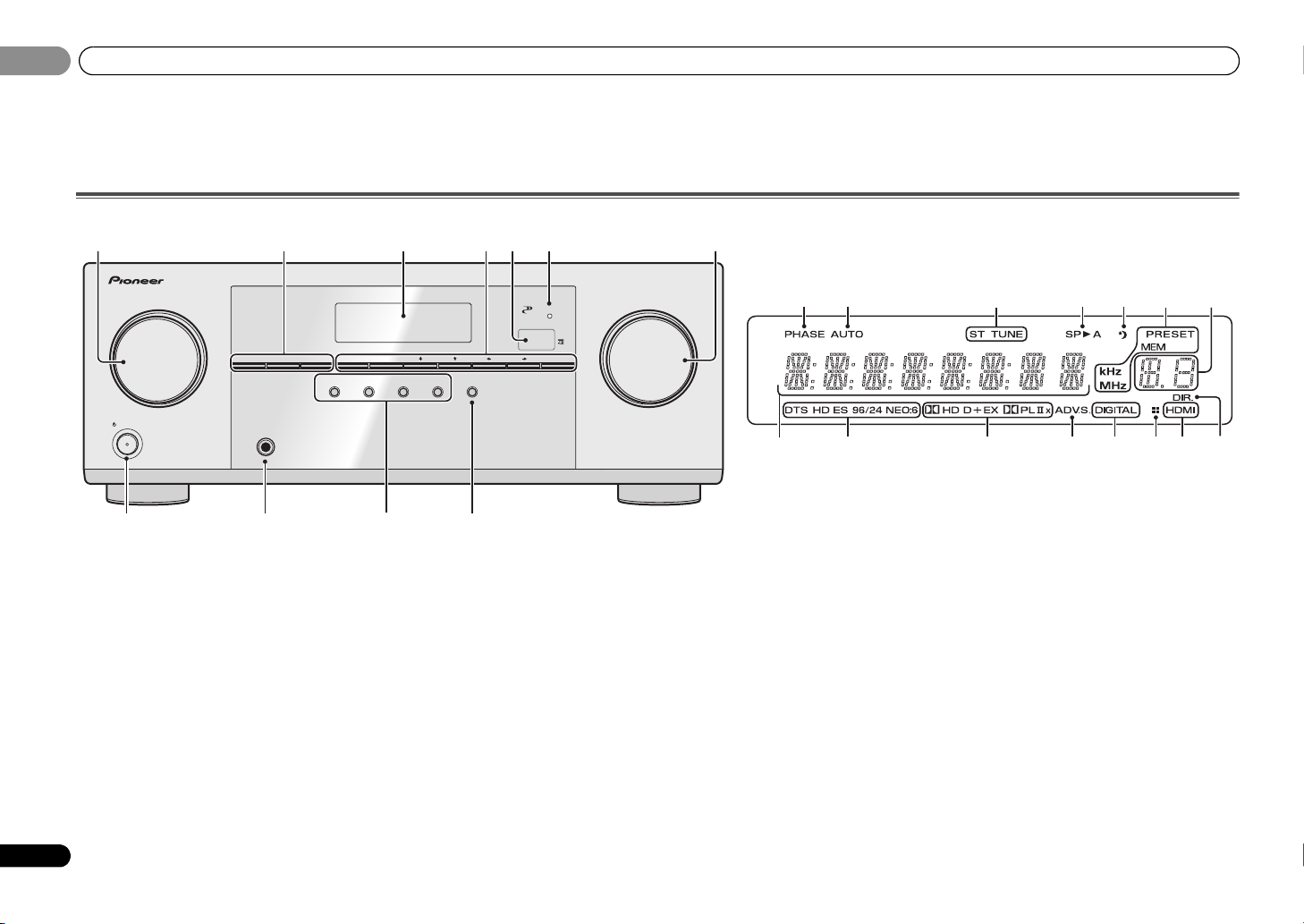
Front panel
1 INPUT SELECTOR dial
Selects an input source (page 17).
2 Receiver control buttons
SPEAKERS – Use to change the speaker system on or off.
When the SP OFF is selected, no sound is output from the
speakers connected to this receiver.
DIMMER – Dims or brightens the display. The brightness
can be controlled in four steps.
DISPLAY – Switches the display of this unit. The listening
mode, sound volume or input name can be checked by
selecting an input source.
3 Character display
See Display on page 7.
4 Tuner control buttons
BAND – Switches between AM, FM ST (stereo) and FM
MONO radio bands (page 18).
6
En
TUNER EDIT – Use with TUNE /, PRESET / and
ENTER to memorize and name stations for recall
(page 18).
TUNE / – Used to find radio frequencies (page 18).
PRESET / – Use to select preset radio stations
(page 19).
5 Remote sensor
Receives the signals from the remote control (see Operating
range of remote control on page 9).
6 HDMI indicator
Blinks when connecting an HDMI-equipped component;
lights when the component is connected (page 14).
7 MASTER VOLUME dial
8
STANDBY/ON
9 PHONES jack
Use to connect headphones. When the headphones are
connected, there is no sound output from the speakers. The
listening mode when the sound is heard from the headphone
can be selected only from PHONES SURR, STEREO or
STEREO ALC mode.
10 Listening mode buttons
AUTO SURROUND/STREAM DIRECT – Switches
between Auto surround mode (page 21) and Stream
Direct playback (page 22).
ALC/STANDARD SURR – Press for standard decoding
and to switch between the modes of 2 Pro Logic II, 2
Pro Logic IIx and NEO:6, and the Auto level control stereo
mode (page 21).
ADVANCED SURROUND – Switches between the
various surround modes (page 22).
STEREO – Press to select stereo playback (page 21).
Page 7

Controls and displays
English
Français
Español
01
01
11 SOUND RETRIEVER
Press to restore CD quality sound to compressed audio
sources (page 22).
Display
12 PHASE
Lights when the Phase Control is switched on (page 22).
13 AUTO
Lights when the Auto Surround feature is switched on
(page 21).
14 Tuner indicators
ST – Lights when a stereo FM broadcast is being received
in auto stereo mode (page 18).
TUNE – Lights when a normal broadcast channel.
PRESET – Shows when a preset radio station is registered
or called.
MEM – Blinks when a radio station is registered.
kHz/MHz – Lights when the character display is showing
the currently received AM/FM broadcast frequency.
15 Speaker indicators
Shows if the speaker system is on or not (page 6).
SPA means the speakers are switched on.
SP means the speakers are switched off.
16 Sleep timer indicator
Lights when the receiver is in sleep mode (page 8).
17 PRESET information or input signal indicator
Shows the preset number of the tuner or the input signal
type, etc.
18 Character display
Displays various system information.
19 DTS indicators
DTS – Lights when a source with DTS encoded audio
signals is detected.
HD – Lights when a source with DTS-EXPRESS or DTS-
HD encoded audio signals is detected.
ES – Lights to indicate DTS-ES decoding.
96/24 – Lights when a source with DTS 96/24 encoded
audio signals is detected.
NEO:6 – When one of the NEO:6 modes of the receiver is
on, this lights to indicate NEO:6 processing (page 21).
20 Dolby Digital indicators
2D – Lights when a Dolby Digital encoded signal is
detected.
2D+ – Lights when a source with Dolby Digital Plus
encoded audio signals is detected.
2HD – Lights when a source with Dolby TrueHD
encoded audio signals is detected.
EX – Lights to indicate Dolby Digital EX decoding.
2PLII(x) – Lights to indicate 2 Pro Logic II/2 Pro Logic
IIx decoding (see Listening in surround sound on page 21
for more on this).
21 ADV.S.
Lights when one of the Advanced Surround modes has been
selected (see Using the Advanced surround on page 22 for
more on this).
22 SIGNAL SELECT indicators
DIGITAL – Lights when a digital audio signal is selected.
Blinks when a digital audio signal is selected and
selected audio input is not provided.
HDMI – Lights when an HDMI signal is selected. Blinks
when an HDMI signal is selected and selected HDMI
input is not provided.
23 Up Mix/DIMMER indicator
Lights when the Up Mix function is set to ON (page 23). Also,
lights when DIMMER is set to off.
24 DIR.
Lights when the DIRECT or PURE DIRECT mode is switched
on (page 22).
7
En
Page 8

01
BD DVD
INPUT SELECT
SOURCESLEEP
TV
CONTROL
DIMMER
TV
INPUT
1
4
7
MIDNIGHT
HDD
CH
RECEIVER
DVR/BDR
CD
CD-R
ADAPTER
TUNER
PORTABLE
PHASE
SIGNAL SELS.RETRIEVER
BD MENU
ENTER
ADV SURR
AUTO/
DIRECT
VOL
+
10
2
5
8
SPEAKERS
LEV
LEV
SB CH
DISP
CLR
TEST TONE
DVD
3
6
9
0
ENTER
CH
CH
CH SELECT
VCR
SHIFT
MUTE
RETURN
AUDIO
PARAMETER
TUNER EDIT
TOOLS
MASTER
VOLUME
BAND
MENU
HOME
MENU
SETUP
PTY SEARCH
TRE
BASS
TOP
MENU
RECEIVER
T
U
N
E
T
U
N
E
P
R
E
S
E
T
P
R
E
S
E
T
RECEIVER DTV/TV
ALC/
STANDARD
STEREO
1
2
12
13
14
15
16
3
4
6
5
7
8
9
10
11
17
RECEIVER
RECEIVER
01
Controls and displays
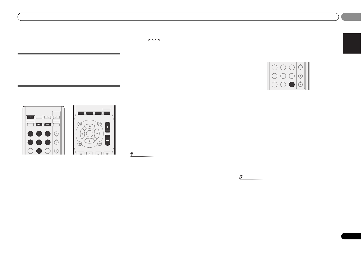
Remote control
As for operating other devices, the remote control codes for
the Pioneer products are preset. The settings cannot be
changed.
1SLEEP
Press to change the amount of time before the receiver
switches into standby (30 min – 60 min – 90 min – Off). You
can check the remaining sleep time at any time by pressing
SLEEP once.
2
RECEIVER
Switches the receiver between standby and on.
3
Switches the remote to control the receiver (used to select
the white commands above the number buttons
(MIDNIGHT, etc)). Also use this button to set up surround
sound (page 25) or Audio parameters (page 23).
4 INPUT SELECT
Use to select the input source (page 17).
5 Input function buttons
Use to select the input source to this receiver (page 17). This
will enable you to control other Pioneer components with the
remote control.
• ADAPTER, PORTABLE button is not used with this
receiver.
6 Receiver control buttons
PHASE – Press to switch on/off Phase Control (page 22).
S.RETRIEVER – Press to restore CD quality sound to
compressed audio sources (page 22).
SIGNAL SEL – Press to select the audio input signal of the
component to play back (page 17).
7 Listening mode buttons
AUTO/DIRECT – Switches between Auto surround mode
(page 21) and Stream Direct playback (page 22).
STEREO – Press to select stereo playback (page 21).
ALC/STANDARD – Press for standard decoding and to
switch between the modes of 2 Pro Logic II, 2 Pro
Logic IIx and NEO:6, and the Auto level control stereo
mode (page 21).
ADV SURR – Switches between the various surround
modes (page 22).
Press BD first to access:
BD MENU* – Displays the disc menu of Blu-ray Discs.
8 System Setup and component control buttons
The following button controls can be accessed after you have
selected the corresponding input function button (BD, DVD,
etc.).
Press first to access:
AUDIO PARAMETER – Use to access the Audio options
(page 23).
SETUP – Press to access the System Setup menu
(page 25).
RETURN – Confirm and exit the current menu screen.
Press BD, DVD or DVR/BDR first to access:
TOP MENU – Displays the disc ‘top’ menu of a Blu-ray
Disc/DVD.
HOME MENU – Displays the HOME MENU screen.
RETURN – Confirm and exit the current menu screen.
MENU – Displays the TOOLS menu of Blu-ray Disc player.
Press TUNER first to access:
TUNER EDIT – Memorizes stations for recall (page 18),
also used to change the name (page 19).
BAND – Switches between AM, FM ST (stereo) and FM
MONO radio bands (page 18).
9
///
(TUNE
/
, PRESET
/
), ENTER
Use the arrow buttons when setting up your surround sound
system (page 25). Also used to control Blu-ray Disc/DVD
menus/options.
Use TUNE / can be used to find radio frequencies and
PRESET / can be used to select preset radio stations
(page 19).
10 Component control buttons
The main buttons (, , etc.) are used to control a
component after you have selected it using the input function
buttons.
The controls above these buttons can be accessed after you
have selected the corresponding input function button (BD,
DVD, DVR/BDR and CD). These buttons also function as
described below.
8
En
Page 9
Controls and displays
English
Français
Español
CAUTION
RECEIVER
RECEIVER
30°
7 m
30°
01
01
Press first to access:
BASS –/+, TRE –/+ – Use to adjust Bass or Treble.
• These controls are disabled when the listening mode is
set to DIRECT or PURE DIRECT.
• When the front speaker is set at SMALL in the Speaker
Setting and the Crossover Network is set above 150 Hz,
the subwoofer channel level will be adjusted by
pressing BASS –/+ (page 25).
11 Number buttons and other component controls
Use the number buttons to directly select a radio frequency
(page 18) or the tracks on a CD, etc. There are other buttons
that can be accessed after is pressed. (For
example MIDNIGHT, etc.)
HDD*, DVD*, VCR* – These buttons switch between the
hard disk, DVD and VCR controls for HDD/DVD/VCR
recorders.
SB CH – Press to select ON, AUTO or OFF the surround
back channel (page 23).
CH SELECT – Press repeatedly to select a channel, then
use LEV +/– to adjust the level (page 26).
LEV +/– – Use to adjust the channel level.
MIDNIGHT – Switches to Midnight or Loudness listening
(page 23).
SPEAKERS – Use to change the speaker system on or off.
When the SP OFF is selected, no sound is output from the
speakers connected to this receiver.
DIMMER – Dims or brightens the display. The brightness
can be controlled in four steps.
12
SOURCE
Turns on or off the power of the Pioneer DVD/DVR units when
BD, DVD, DVR/BDR or CD is selected using the input
function buttons.
13 TV CONTROL buttons
These buttons can control only be used with Pioneer TVs.
– Use to turn on/off the power of the TV.
INPUT – Use to select the TV input signal.
CH +/– – Use to select channels.
VOL +/– – Use to adjust the volume on your TV.
DTV/TV* – Switches between the DTV and analog TV
input modes for Pioneer TVs.
14 MASTER VOLUME +/–
Use to set the listening volume.
15 MUTE
Mutes/unmutes the sound.
16 DISP
Switches the display of this unit. The listening mode, sound
volume or input name can be checked by selecting an input
source.
17 SHIFT
Press to access the ‘boxed’ commands (above the buttons)
on the remote. These buttons are marked with an asterisk (*)
in this section.
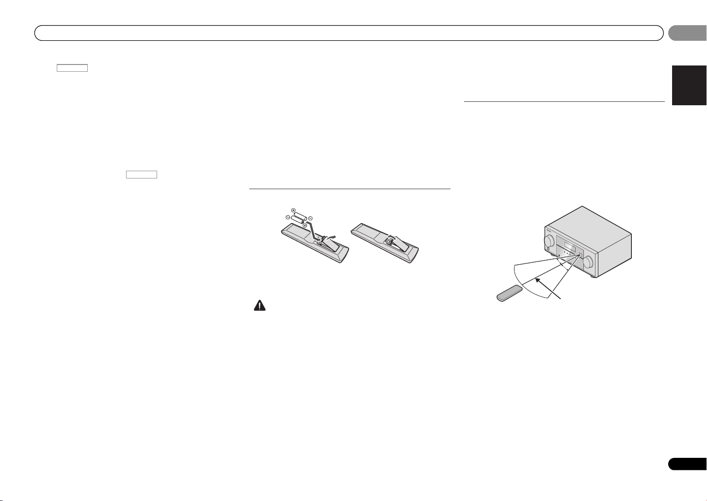
Loading the batteries
The batteries included with the unit are to check initial
operations; they may not last over a long period. We
recommend using alkaline batteries that have a longer life.
• Incorrect use of batteries may result in such hazards as
leakage and bursting. Observe the following precautions:
-
Never use new and old batteries together.
-
Insert the plus and minus sides of the batteries properly
according to the marks in the battery case.
-
Batteries with the same shape may have different
voltages. Do not use different batteries together.
-
When disposing of used batteries, please comply with
governmental regulations or environmental public
instruction’s rules that apply in your country or area.
-
Do not use or store batteries in direct sunlight or other
excessively hot place, such as inside a car or near a
heater. This can cause batteries to leak, overheat,
explode or catch fire. It can also reduce the life or
performance of batteries.
WARNING
Store the batteries out of the reach of children and infants. If
accidentally swallowed, contact a doctor immediately.
Operating range of remote control
The remote control may not work properly if:
• There are obstacles between the remote control and the
receiver’s remote sensor.
• Direct sunlight or fluorescent light is shining onto the
remote sensor.
• The receiver is located near a device that is emitting
infrared rays.
• The receiver is operated simultaneously with another
infrared remote control unit.
9
En
Page 10
02
CAUTION
Important
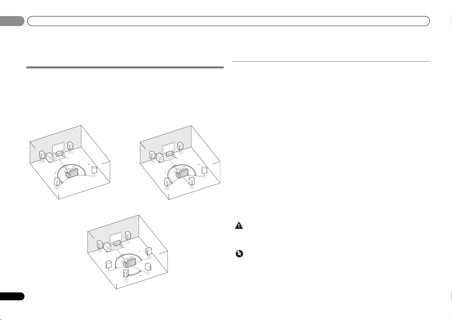
5.1 channel surround system:
7.1 channel surround system:
a
6.1 channel surround system:
a
02
Connecting your equipment
Chapter 2:
Connecting your equipment
Placing the speakers
By connecting the left and right front speakers (L/R), the center speaker (C), the left and right
surround speakers (
Further, by using an external amplifier, you can connect the left and right surround back
speakers (SBL/SBR) to boost your system up to a 7.1 ch surround system.
• You can also connect one surround back speaker (SB) and enjoy a 6.1 ch surround system.
To achieve the best possible surround sound, install your speakers as shown below.
L
SW
120
SL
SL/SR
), and the subwoofer (SW), a 5.1 ch surround system can be enjoyed.
R
C
120
SR
L
SW
120
SL
R
C
120
SB
SR
a. This layout is available only when the additional amplifier is connected to the unit and the
surround back speakers are connected to the amplifier. For details, see Connect th e surround back
speakers on page 11.
Hints on the speaker placement
Where you put your speakers in the room has a big effect on the quality of the sound. The
following guidelines should help you to get the best sound from your system.
• The subwoofer can be placed on the floor. Ideally, the other speakers should be at about
ear-level when you’re listening to them. Putting the speakers on the floor (except the
subwoofer), or mounting them very high on a wall is not recommended.
• For the best stereo effect, place the front speakers 2 m to 3 m apart, at equal distance from
the TV.
• If you’re going to place speakers around your CRT TV, use shielded speakers or place the
speakers at a sufficient distance from your CRT TV.
• If you’re using a center speaker, place the front speakers at a wider angle. If not, place
them at a narrower angle.
• Place the center speaker above or below the TV so that the sound of the center channel is
localized at the TV screen. Also, make sure the center speaker does not cross the line
formed by the leading edge of the front left and right speakers.
• It is best to angle the speakers towards the listening position. The angle depends on the
size of the room. Use less of an angle for bigger rooms.
• Surround and surround back speakers should be positioned 60 cm to 90 cm higher than
your ears and titled slight downward. Make sure the speakers don’t face each other. For
DVD-Audio, the speakers should be more directly behind the listener than for home
theater playback.
• If the surround speakers cannot be set directly to the side of the listening position with a
7.1-channel system, the surround effect can be enhanced by turning off the Up Mix
function (see Setting the Up Mix function on page 23).
• Try not to place the surround speakers farther away from the listening position than the
front and center speakers. Doing so can weaken the surround sound effect.
10
En
R
L
SW
SL
90
SBL
C
SR
90
SBR
60
• Make sure that all speakers are securely installed. This not only improves sound quality,
but also reduces the risk of damage or injury resulting from speakers being knocked over
or falling in the event of external shocks such as earthquakes.
• To connect the surround back speakers, an additional amplifier is required. Connect the
additional amplifier to the SURR BACK PRE OUT outputs of this unit and connect the
surround back speakers to the additional amplifier (see Connect the surround back
speakers on page 11).
Page 11
Connecting your equipment
English
Français
Español
CAUTION
12
HDMI
VIDEO
L
R
R
L
COAXIAL
AUDIO
SPEAKERS
ANTENNA
OPTICAL
ASSIGNABLE
OUT
A
CD-R/TAPE
OUT
SURR BACK
PRE OUT
L
R
(
Single
)
(
CD-R / TAPE
)
IN CD/SAT
MONITOR
OUT
CD/SAT
DVD
IN
TV
IN
IN
DVD
DVR/BDR IN DVD IN BD IN CD/SAT
(TV)
IN
1
IN
1
FM
UNBAL
75
AM LOOP
FRONT CENTER
SURROUND SUBWOOFER
RLRL
ANALOG
RL
AUDIO IN
SPEAKER R SPEAKER L
Center
Surround right
Front right
Front left
Subwoofer
Surround left
Surround back
right
Surround back
left
Surround back channel amplifier
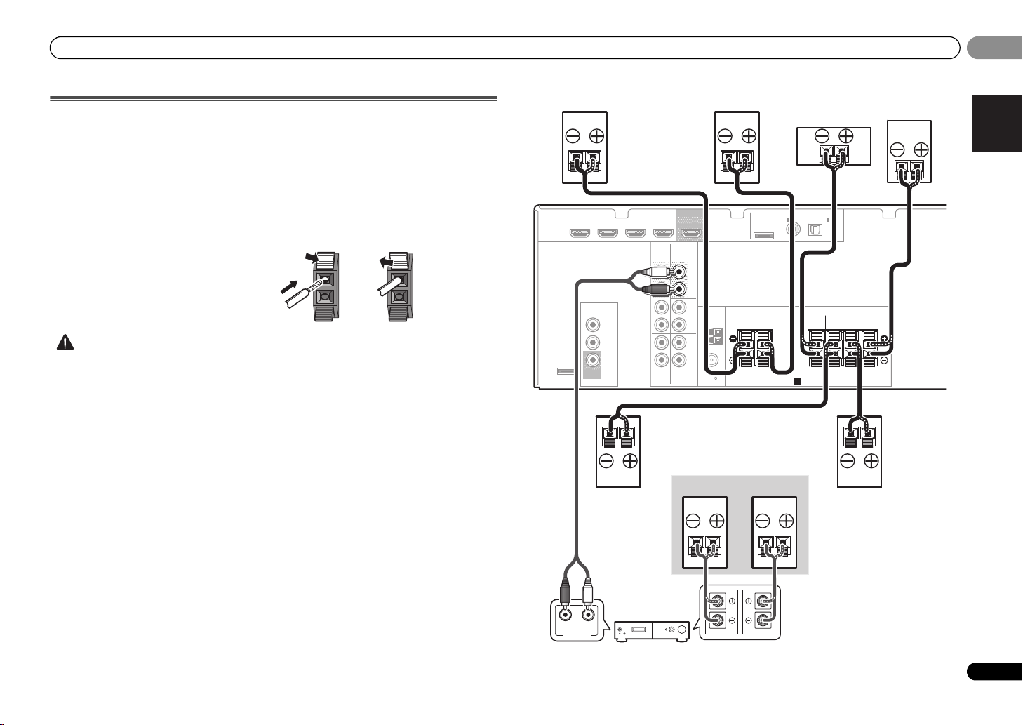
Connecting the speakers
The receiver will work with just two stereo speakers (the front speakers in the diagram) but
using at least three speakers is recommended, and a complete setup is best for surround
sound.
Make sure you connect the speaker on the right to the right (R) terminal and the speaker on
the left to the left (L) terminal. Also make sure the positive and negative (+/–) terminals on the
receiver match those on the speakers.
Be sure to complete all connections before connecting this unit to the AC power source.
Bare wire connections
1 Push open the tabs and insert exposed
wire.
2 Release the tabs.
• These speaker terminals carry HAZARDOUS LIVE voltage. To prevent the risk of electric
shock when connecting or disconnecting the speaker cables, disconnect the power cord
before touching any uninsulated parts.
• Make sure that all the bare speaker wire is inserted fully into the speaker terminal. If any
of the bare speaker wire touches the back panel it may cause the power to cut off as a
safety measure.
Connect the surround back speakers
Connect the SURR BACK PRE OUT outputs of the unit and additional amplifier to add a
surround back speaker.
• You can use the additional amplifier on the surround back channel pre-outs for a single
speaker as well. In this case plug the amplifier into the left (L (Single)) terminal only.
02
02
11
En
Page 12
02
Important
Note
Note
HDMI
02
Connecting your equipment
Making cable connections
Make sure not to bend the cables over the top of this unit. If
this happens, the magnetic field produced by the
transformers in this unit may cause a humming noise from
the speakers.
• Before making or changing connections, switch off the
power and disconnect the power cord from the AC outlet.
• Before unplugging the power cord, switch the power into
standby.
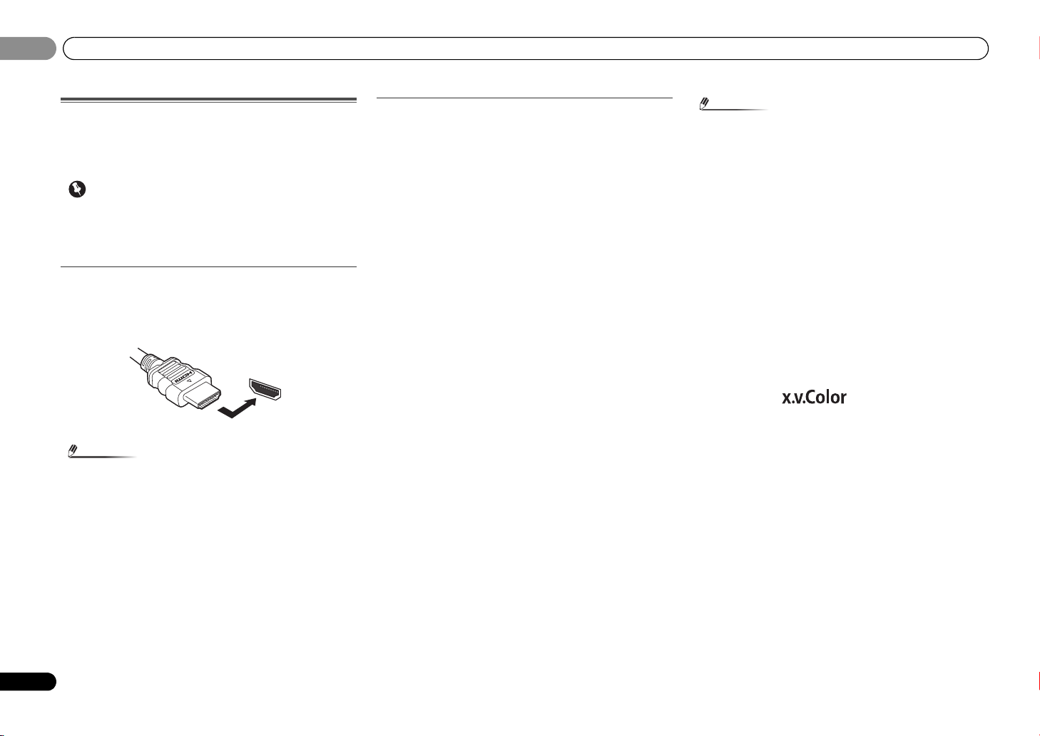
HDMI cables
Both video and sound signals can be transmitted
simultaneously with one cable. If connecting the player and
the TV via this receiver, for both connections, use HDMI
cables.
Be careful to connect the terminal in the proper direction.
• Set the HDMI parameter in Setting the Audio options on
page 23 to THRU (THROUGH) and set the input signal in
Selecting the audio input signal on page 17 to HDMI, if you
want to hear HDMI audio output from your TV (no sound
will be heard from this receiver).
• If the video signal does not appear on your TV, try
adjusting the resolution settings on your component or
di sp la y. No te tha t s om e c om pon en ts (s uc h as v id eo ga me
units) have resolutions that may not be displayed. In this
case, use a (analog) composite connection.
• When the video signal from the HDMI is 480i, 480p, 576i
or 576p, Multi Ch PCM sound and HD sound cannot be
received.
About HDMI
The HDMI connection transfers uncompressed digital video,
as well as almost every kind of digital audio that the
connected component is compatible with, including DVDVideo, DVD-Audio, Dolby Digital Plus, Dolby TrueHD, DTSHD Master Audio (see below for limitations), Video CD/Super
VCD and CD.
This receiver incorporates High-Definition Multimedia
Interface (HDMI
This receiver supports the functions described below through
HDMI connections.
• Digital transfer of uncompressed video (contents
protected by HDCP (1080p/24, 1080p/60, etc.))
• 3D signal transfer
• Deep Color signal transfer
• x.v.Color signal transfer
• Audio Return Channel
(see ARC (Audio Return Channel) function on page 27)
• Input of multi-channel linear PCM digital audio signals
(192 kHz or less) for up to 8 channels
• Input of the following digital audio formats:
– Dolby Digital, Dolby Digital Plus, DTS, High bitrate
audio (Dolby TrueHD, DTS-HD Master Audio), DVDAudio, CD, Video CD, Super VCD.
®
) technology.
• Use a High Speed HDMI® cable. If HDMI cable other than
a High Speed HDMI
properly.
• When an HDMI cable with a built-in equalizer is
connected, it may not operate properly.
• 3D, Deep Color, x.v.Color signal transfer and Audio
Return Channel are only possible when connected to a
compatible component.
• HDMI format digital audio transmissions require a longer
time to be recognized. Due to this, interruption in the
audio may occur when switching between audio formats
or beginning playback.
• Turning on/off the device connected to this unit’s HDMI
OUT terminal during playback, or disconnecting/
connecting the HDMI cable during playback, may cause
noise or interrupted audio.
HDMI, the HDMI Logo and High-Definition Multimedia
Interface are trademarks or registered trademarks of HDMI
Licensing, LLC in the United States and other countries.
“x.v.Color” and are trademarks of Sony
Corporation.
®
cable is used, it may not work
12
En
Page 13
Connecting your equipment
English
Français
Español
Note
L
R
AUDIO
White (Left)
Red (Right)
COAXIAL
IN
OPTICAL
IN
Coaxial digital
audio cable
Optical cable
VIDEO
Yellow
VIDEO
VIDEO
IN
IN
HDMI
MONITOR
OUT
HDMI
OUT
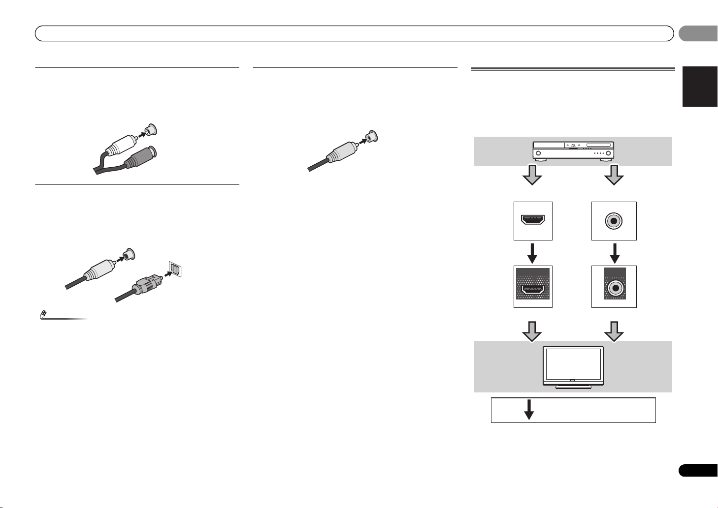
Terminal for connection with source device
Terminal for connection with TV monitor
Playback
component
TV
Video signals can be output.
02
02
Analog audio cables
Use stereo RCA phono cables to connect analog audio
components. These cables are typically red and white, and
you should connect the red plugs to R (right) terminals and
white plugs to L (left) terminals.
Digital audio cables
Commercially available coaxial digital audio cables or optical
cables should be used to connect digital components to this
receiver.
• When connecting optical cables, be careful when
inserting the plug not to damage the shutter protecting
the optical socket.
• When storing optical cable, coil loosely. The cable may be
damaged if bent around sharp corners.
• You can also use a standard RCA video cable for coaxial
digital connections.
Video cables
Standard RCA video cables
These cables are the most common type of video connection
and are used to connect to the composite video terminals.
The yellow plugs distinguish them from cables for audio.
About video outputs connection
This receiver is not loaded with a video converter. When you
use HDMI cables for connecting to the input device, the
same cables should be used for connecting to the TV.
The signals input from the analog (composite) video inputs of
this unit will not be output from the HDMI OUT.
13
En
Page 14
02
Note
HDMI
VIDEO
L
R
R
L
COAXIAL
AUDIO
SPEAKERS
ANTENNA
OPTICAL
ASSIGNABLE
OUT
A
CD-R/TAPE
OUT
SURR BACK
PRE OUT
L
R
(
Single
)
(
CD-R / TAPE
)
IN CD/SAT
MONITOR
OUT
CD/SAT
DVD
IN
TV
IN
IN
DVD
DVR/BDR IN
DVD IN
BD IN
CD/SAT
(TV)
IN
1
IN
1
FM
UNBAL
75
AM LOOP
FRONT
CENTER
SURRO
RRL
HDMI IN
HDMI OUT
RL
DIGITAL AUDIO OUTANALOG AUDIO OUT
OPTICAL
Select one
HDMI/DVI-
compatible TV
HDMI/DVI-compatible
Blu-ray Disc player
If the TV does not support the HDMI
Audio Return Channel function, this
connection is required to listen to the
TV sound over the receiver.
RL
DIGITAL AUDIO OUT ANALOG AUDIO OUT
OPTICAL
RL
DIGITAL AUDIO OUTANALOG AUDIO OUT
COAXIAL
VIDEO IN
VIDEO OUT
Select one
TV
DVD player
Select one
This connection is
required in order to
listen to the sound of
the TV over the
receiver.
02
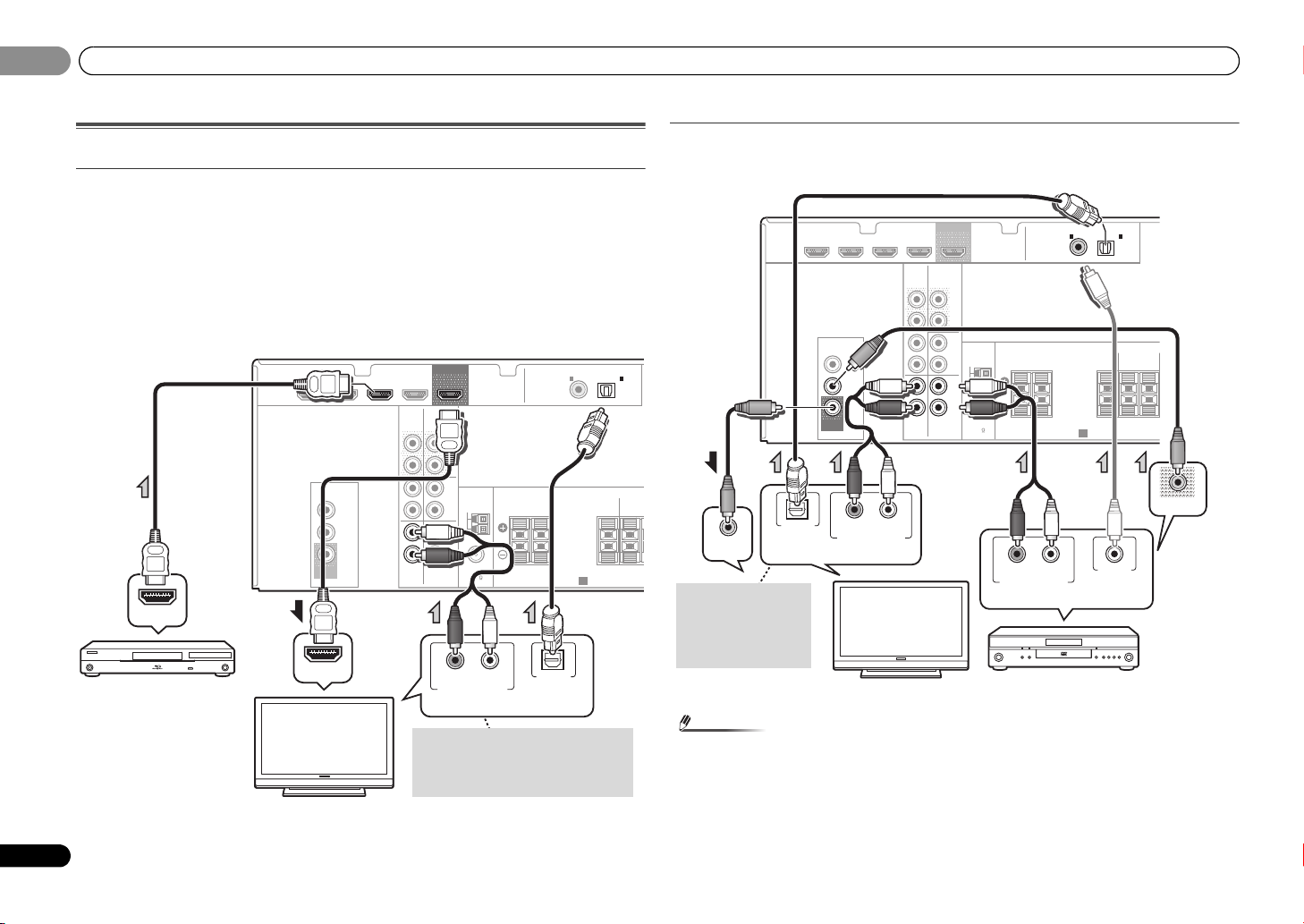
Connecting your equipment
Connecting a TV and playback components
Connecting using HDMI
If you have an HDMI or DVI (with HDCP) equipped component (Blu-ray Disc player, etc.), you
can connect it to this receiver using a commercially available HDMI cable.
• The following connection/setting is required to listen to the sound of the TV over this
receiver.
-
If the TV does not support the HDMI Audio Return Channel function, connect the receiver
and TV with audio cables (as shown).
-
If the TV supports the HDMI Audio Return Channel function, the sound of the TV is input
to the receiver via the HDMI terminal, so there is no need to connect an audio cable. In
this case, set ARC at HDMI SET to ON (see ARC Setup on page 27).
Connecting your component with no HDMI terminal
This diagram shows connections of a TV and DVD player (or other playback component) with
no HDMI terminal to the receiver.
FM
UNBAL
75
ASSIGNABLE
COAXIAL
1
IN
(
)
(TV)
CD-R / TAPE
FRONT CENTER
A
SPEAKERS
OPTICAL
1
IN
SURROUND
RLRL
HDMI
DVR/BDR IN
VIDEO
MONITOR
OUT
DVD IN
CD/SAT
CD/SAT
AUDIO
CD-R/TAPE
SURR BACK
OUT
PRE OUT
IN CD/SAT
IN
DVD
TV
OUT
L
(
Single
R
L
R
L
IN
R
)
ANTENNA
IN
AM LOOP
BD IN
DVD
14
En
• In order to listen to the audio from the DVD player that is connected to this receiver using
a coaxial cable, first, switch to the DVD input, then press SIGNAL SEL to choose the audio
signal C1 (COAXIAL1) (see Selecting the audio input signal on page 17).
Page 15
Connecting your equipment
English
Français
Español
Note
Note
VIDEO
L
R
R
L
COAXIAL
AUDIO
SPEAKERS
ANTENNA
OPTICAL
ASSIGNABLE
OUT
A
CD-R/TAPE
OUT
SURR BACK
PRE OUT
L
R
(
Single
)
(
CD-R / TAPE
)
IN CD/SAT
MONITOR
OUT
CD/SAT
DVD
IN
TV
IN
IN
DVD
DVR/BDR IN
DVD IN
BD IN
CD/SAT
(TV)
IN
1
IN
1
FM
UNBAL
75
AM LOOP
FRONT CENTER
SURROUN
RRL
RL
DIGITAL AUDIO OUTANALOG AUDIO OUT
OPTICALCOAXIAL
VIDEO OUT
Select one
Set-top box, etc.
VIDEO
L
R
R
L
COAXIAL
AUDIO
SPEAKERS
ANTENNA
OPTICAL
ASSIGNABLE
OUT
A
CD-R/TAPE
OUT
SURR BACK
PRE OUT
L
R
(
Single
)
(
CD-R / TAPE
)
IN CD/SAT
MONITOR
OUT
CD/SAT
DVD
IN
TV
IN
IN
DVD
DVR/BDR IN
DVD IN
BD IN
CD/SAT
(TV)
IN
1
IN
1
FM
UNBAL
75
AM LOOP
FRONT CENTER
SURRO
RRL
REC
RL
DIGITAL AUDIO OUTANALOG AUDIO OUT
RL
ANALOG AUDIO IN
OPTICALCOAXIAL
Select one
CD-R, MD, DAT,
Tape recorder, etc.
ANTENNA
FM
UNBAL
75
AM LOOP
2
1
3
4
fig. a
fig. b
02
02
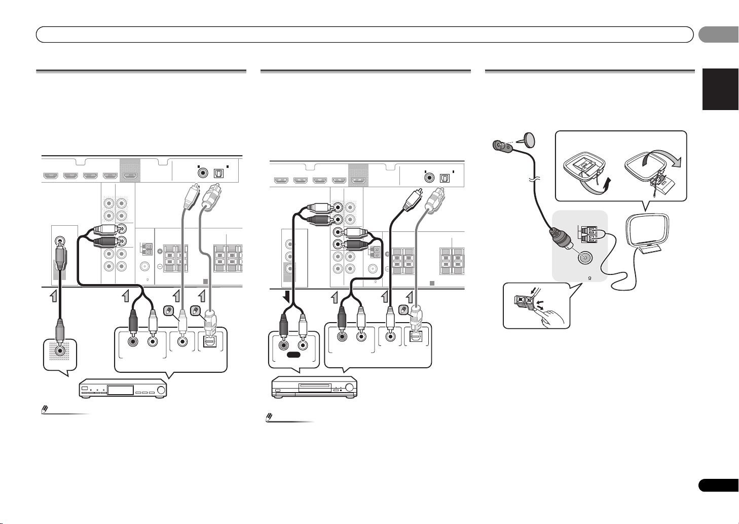
Connecting a satellite receiver or other digital
set-top box
Satellite and cable receivers, and terrestrial digital TV tuners
are all examples of so-called ‘set-top boxes’.
• If the set-top box or video component also has an HDMI
output, you can connect this too. See Connecting using
HDMI on page 14 for more on this.
• In order to listen to the audio from the source component
that is connected to this receiver using a coaxial cable or
an optical cable, first, switch to the CD/SAT, then press
SIGNAL SEL to choose the audio signal C1 (COAXIAL1) or
O1 (OPTICAL1) (see Selecting the audio input signal on
page 17).
Connecting other audio components
The number and kind of connections depends on the kind of
component you’re connecting. Follow the steps below to
connect a CD-R, MD, DAT, tape recorder or other audio
component.
• Note that you must connect digital components to analog
audio jacks if you want to record to/from digital
components (like an MD) to/from analog components.
• In order to listen to the audio from the CD player that is
connected to this receiver using an optical cable, first,
switch to the CD-R input, then press SIGNAL SEL to
choose the audio signal O1 (OPTICAL1) (see Selecting the
audio input signal on page 17).
Connecting antennas
Connect the AM loop antenna and the FM wire antenna as
shown below. To improve reception and sound quality,
connect external antennas (see Using external antennas
below).
1 Push open the tabs, then insert one wire fully into each
terminal, then release the tabs to secure the AM antenna
wires.
2 Fix the AM loop antenna to the attached stand.
To fix the stand to the antenna, bend in the direction
indicated by the arrow (fig. a) then clip the loop onto the
stand (fig. b).
3 Place the AM antenna on a flat surface and in a direction
giving the best reception.
4 Connect the FM wire antenna into the FM antenna
socket.
For best results, extend the FM antenna fully and fix to a wall
or door frame. Don’t drape loosely or leave coiled up.
15
En
Page 16
02
CAUTION
Note
ANTENNA
FM
UNBAL
75
75 Ω coaxial cable
J-shaped plug
(not supplied)
ANTENNA
AM LOOP
Outdoor
antenna
5 m to 6 m
Indoor antenna
(vinyl-coated wire)
02
Connecting your equipment
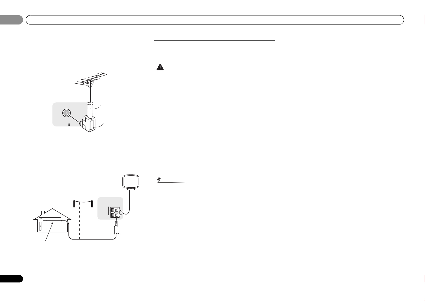
Using external antennas
To improve FM reception
Use a PAL connector (not supplied) to connect an external
FM antenna.
To improve AM reception
Connect a 5 m to 6 m length of vinyl-coated wire to the AM
antenna terminal without disconnecting the supplied AM
loop antenna.
For the best possible reception, suspend horizontally
outdoors.
Plugging in the receiver
Only plug in after you have connected all your components to
this receiver, including the speakers.
• Handle the power cord by the plug part. Do not pull out
the plug by tugging the cord, and never touch the power
cord when your hands are wet, as this could cause a short
circuit or electric shock. Do not place the unit, a piece of
furniture, or other object on the power cord or pinch the
co rd in any other way . Never m ake a k not in the co rd or tie
it with other cables. The power cords should be routed so
that they are not likely to be stepped on. A damaged
power cord can cause a fire or give you an electric shock.
Check the power cord once in a while. If you find it
damaged, ask your nearest Pioneer authorized
independent service company for a replacement.
• Do not use any power cord other than the one supplied
with this unit.
• Do not use the supplied power cord for any purpose other
than that described below.
• The receiver should be disconnected by removing the
mains plug from the wall socket when not in regular use,
e.g., when on vacation.
• After this receiver is connected to an AC outlet, a 2
second to 10 second HDMI initialization process begins.
You cannot carry out any operations during this process.
The HDMI indicator in the front panel display blinks
during this process, and you can turn on this receiver
once it has stopped blinking. When you set ARC at HDMI
setup to OFF, you can skip this process. For details, see
ARC (Audio Return Channel) function on page 27.
1 Plug the supplied power cord into the AC IN socket on
the back of the receiver.
2 Plug the other end into a power outlet.
16
En
Page 17
Basic playback
English
Français
Español
Note
Note
RECEIVER
CH
VOL
DVR/BDR
CD
CD-R
ADAPTER
TUNER
PORTABLE
PHASE
SIGNAL SELS.RETRIEVER
03
03
Chapter 3:
Basic playback
Canceling the demo display
The display on the front panel shows various information
(demo displays) when the receiver is not operating.
You can turn off the demo display. For details, see The FL
Demo Mode menu on page 26.
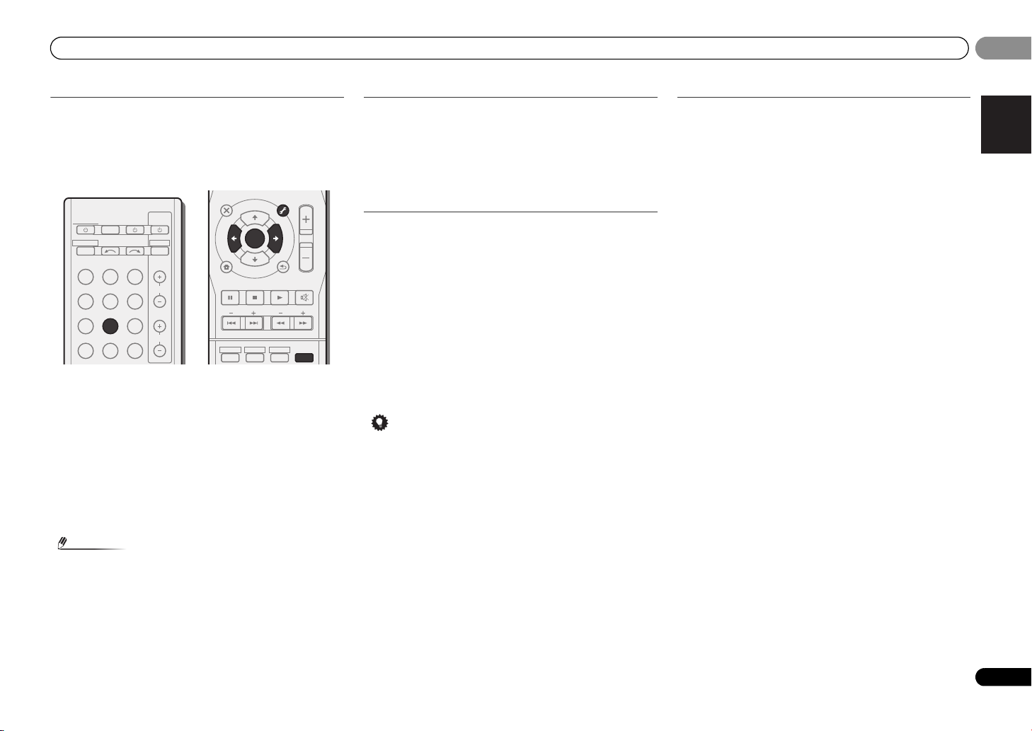
Playing a source
Here are the basic instructions for playing a source (such as
a DVD disc) with your home theater system.
N
E
E
N
ALC/
STANDARD
TUNER EDIT
TOOLS
P
R
E
S
E
T
RETURN
BD MENU
ADV SURR
MASTER
VOLUME
MENU
BAND
MUTE
AUTO/
DIRECT
RECEIVER
RECEIVER
INPUT SELECT
BD DVD TV
DVR/BDR
CD
TUNER
ADAPTER
SOURCESLEEP
CD-R
PORTABLE
TV
CONTROL
DTV/TV
INPUT
CH
AUDIO
PARAMETER
TOP
MENU
T
E
S
E
R
P
HOME
MENU
SETUP
PTY SEARCH
STEREO
U
T
ENTER
T
U
1 Switch on your system components and receiver.
Start by switching on the playback component (for example a
DVD player), your TV, then the receiver (press RECEIVER).
2 Switch the TV input to the input that connects this
receiver.
For example, if you connected this receiver to the VIDEO
jacks on your TV, make sure that the VIDEO input is now
selected.
3 Press input function buttons to select the input function
you want to play.
• The input of the receiver will switch over, and you will be
able to operate other components using the remote
control. To operate the receiver, first press on
the remote control, then press the appropriate button to
operate.
• The input source can also be selected by using INPUT
SELECT buttons on the remote control, or by
using the front panel INPUT SELECTOR dial. In this case,
the remote control won’t switch operational modes.
If you selected the proper input source and there is still no
sound, select the audio input signal for playback (see
Selecting the audio input signal below).
4 Press AUTO/DIRECT to select ‘AUTO SURROUND’ and
start playback of the source.
If you’re playing a Dolby Digital or DTS surround sound DVD
disc, with a digital audio connection, you should hear
surround sound. If you’re playing a stereo source or if the
connection is an analog audio connection, you will only hear
sound from the front left/right speakers in the default
listening mode.
It is possible to check on the front panel display whether or
not surround sound playback is being performed properly.
When using a surround back speaker, 2D+PLIIx is
displayed when playing Dolby Digital 5.1-channel signals,
and DTS+NEO:6 is displayed when playing DTS 5.1-channel
signals.
When not using a surround back speaker, 2D is displayed
when playing Dolby Digital signals.
If the display does not correspond to the input signal and
listening mode, check the connections and settings.
• You may need to check the digital audio output settings
on your DVD player or digital satellite receiver. It should
be set to output Dolby Digital, DTS and 88.2 kHz/96 kHz
PCM (2 channel) audio, and if there is an MPEG audio
option, set this to convert the MPEG audio to PCM.
• Depending on your DVD player or source discs, you may
only get digital 2 channel stereo and analog sound. In this
case, the receiver must be set to a multichannel listening
mode if you want multichannel surround sound.
5 Use MASTER VOLUME to adjust the volume level.
Turn down the volume of your TV so that all sound is coming
from the speakers connected to this receiver.
Selecting the audio input signal
The audio input signal can be selected for each input source.
Once it is set, the audio input that was selected will be
applied whenever you select the input source using the input
function buttons.
Press SIGNAL SEL to select the audio input signal
corresponding to the source component.
Each press cycles through the following:
• H – Selects an HDMI signal. H can be selected for BD,
DVD, DVR/BDR and CD/SAT input. For other inputs, H
cannot be selected.
-
When the HDMI option in Setting the Audio options on
page 23 is set to THRU, the sound will be heard through
your TV, not from this receiver.
• C1/O1 – Selects the digital input. The coaxial 1 input is
selected for C1, and the optical 1 audio input is selected
for O1.
• A – Selects the analog inputs.
When H (HDMI) or C1/O1 (digital) is selected and the
selected audio input is not provided, A (analog) is
automatically selected.
Except BD, DVR/BDR input.
•For the TV input, only A (analog) or C1/O1 (digital) can be
selected. However, if the ARC at HDMI SET is set to ON,
the input is fixed to H (HDMI) and cannot be changed.
•When set to H (HDMI) or C1/O1 (digital), 2 lights when
a Dolby Digital signal is input, and DTS lights when a DTS
signal is input.
•When the H (HDMI) is selected, the A and DIGITAL
indicators are off (see page 7).
17
En
Page 18

03
Tip
Audio
Other than
CD-R/TAPE
input
Audio
Audio
Video/Audio
Video
Other than TV input
(CD-R/TAPE input)
(TV input)
(HDMI)
03
Basic playback
18
En
• When digital input (optical or coaxial) is selected, this
receiver can only play back Dolby Digital, PCM (32 kHz to
96 kHz) and DTS (including DTS 96 kHz/24 bit) digital
signal formats. The compatible signals via the HDMI
terminals are: Dolby Digital, DTS, PCM (32 kHz to 192 kHz
sampling frequencies), Dolby TrueHD, Dolby Digital Plus,
DTS-EXPRESS, DTS-HD Master Audio and DVD Audio
(including 192 kHz). With other digital signal formats, set
to A (analog).
• In order to enjoy the picture and/or sound from devices
connected to each terminal, select the input by doing the following.
1.
DVR/BDR
HDMI
DVD
DVD BD CD
DVR/BDR IN DVD IN BD IN CD/SAT
VIDEO
MONITOR
OUT
CD/SAT
DVD
CD
AUDIO
CD-R/TAPE
OUT
IN CD/SAT
IN
TV
2.
SIGNAL SEL
OUT
SURR BACK
PRE OUT
L
(
)
Single
R
L
ANTENNA
IN
AM LOOP
R
L
IN
R
DVD
CD-R
CD-R CD
FM
UNBAL
75
• You may get digital noise when a LD or CD player
compatible with DTS is playing an analog signal. To
prevent noise, make the proper digital connections
(page 13) and set the signal input to C1/O1 (digital).
• Some DVD players don’t output DTS signals. For more
details, refer to the instruction manual supplied with your
DVD player.
• This product is not compatible with DSD decoding.
Set the output setting on the player to PCM when playing
SACD on a player compatible with SACD. See the player ’s
instruction manual for details.
TV
1.
COAXIAL
1
IN
(
CD-R / TAPE
SPEAKERS
2.
SIGNAL SEL
A
A
)
(TV)
O1
OPTICAL
1
IN
SURROUND
RLRL
C1
ASSIGNABLE
SIGNAL SEL
DVDTV
FRONT CENTER
TUNER
Listening to the radio
The following steps show you how to tune in to FM and AM
radio broadcasts using the automatic (search) and manual
(step) tuning functions. Once you are tuned to a station you
can memorize the frequency for recall later—see Saving
station presets below for more on how to do this.
DVR/BDR
ADAPTER
PHASE
CD
TUNER
CD-R
PORTABLE
SIGNAL SELS.RETRIEVER
AUDIO
PARAMETER
U
T
CH
VOL
TOP
MENU
T
E
S
E
R
HOME
MENU
SETUP
PTY SEARCH
ENTER
P
T
U
N
N
E
E
TUNER EDIT
TOOLS
P
R
E
S
E
T
RETURN
MENU
BAND
MASTER
VOLUME
1 Press TUNER to select the tuner.
2 Use BAND to change the band (FM or AM), if necessary.
Each press switches the band between FM (stereo or mono)
and AM.
3 Tune to a station.
There are three ways to do this:
Automatic tuning
To search for stations in the currently selected band,
press and hold TUNE / for about a second. The
receiver will start searching for the next station, stopping
when it has found one. Repeat to search for other
stations.
Manual tuning
To change the frequency one step at a time, press
TUNE /.
High speed tuning
Press and hold TUNE / for high speed tuning.
Release the button at the frequency you want.
Improving FM sound
If the TUNE or ST indicators don’t light when tuning to an FM
station because the signal is weak, set the receiver to the
mono reception mode.
Press BAND to select FM MONO.
This should improve the sound quality and allow you to enjoy
the broadcast.
Page 19
Basic playback
English
Français
Español
Note
Tip
INPUT SELECT
SOURCESLEEP
TV
CONTROL
INPUT
RECEIVER
CH
VOL
RECEIVER
BD DVD TV
DVR/BDR
CD
CD-R
ADAPTER
TUNER
PORTABLE
PHASE
SIGNAL SELS.RETRIEVER
DTV/TV
1
ENTER
2
DISP
3
MUTE
RETURN
AUDIO
PARAMETER
TUNER EDIT
TOOLS
MASTER
VOLUME
BAND
MENU
TRE
BASS
TOP
MENU
T
U
N
E
T
U
N
E
P
R
E
S
E
T
P
R
E
S
E
T
HDD DVD VCR
HOME
MENU
SETUP
PTY SEARCH
03
03
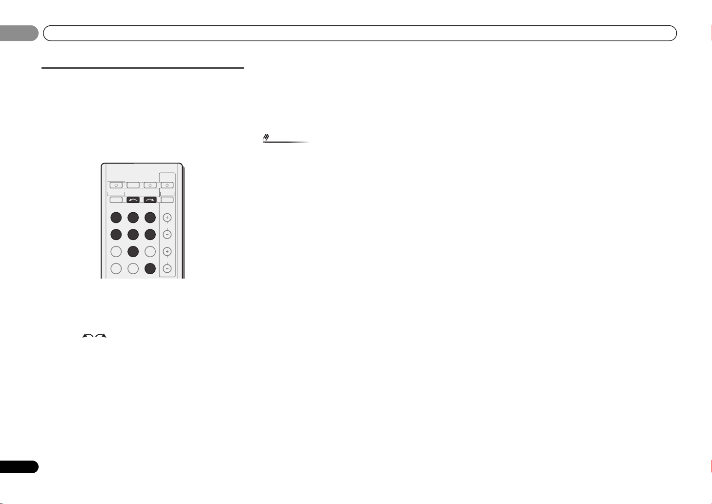
Saving station presets
If you often listen to a particular radio station, it’s convenient
to have the receiver store the frequency for easy recall
whenever you want to listen to that station. This saves the
effort of manually tuning in each time. This unit can
memorize up to 30 stations.
1 Tune to a station you want to memorize.
See Listening to the radio on page 18 for more on this.
2 Press TUNER EDIT.
The display shows PRESET, then a blinking MEM and station
preset.
3 Press PRESET
want.
You can also use the number buttons.
4 Press ENTER.
The preset number stop blinking and the receiver stores the
station.
/
to select the station preset you
Listening to station presets
You will need to have some presets stored to do this. See
Saving station presets above if you haven’t done this already.
Press PRESET
/
to select the station preset you
want.
• You can also use the number buttons on the remote
control to recall the station preset.
Naming preset stations
For easier identification, you can name all of your preset
stations.
1 Choose the station preset you want to name.
See Listening to station presets above for how to do this.
2 Press TUNER EDIT twice.
The cursor at the first character position is blinking on the
display.
3 Input the name you want.
Choose a name up to eight characters long.
•Use PRESET / to select character position.
•Use TUNE / to select characters.
• The name is stored when ENTER is pressed.
• To erase a station name, follow steps 1 and 2, and press
ENTER while the display is blank. Press TUNER EDIT
while the display is blank, to keep the previous name.
• Once you have named a station preset, Press DISP to
show the name. When you want to return to the frequency
display, press DISP several times to show the frequency.
Changing the radio frequency step
If you find that you can’t tune into stations successfully, the
frequency step may not be suitable for your country/region.
Here’s how to switch the setting:
1 Switch the receiver into standby.
While holding down the TUNE button, press and
2
hold the STANDBY/ON button for about two seconds.
• The channel tuning step alternates between 10K STEP
and
9K STEP each time you do this.
• If the receiver is left disconnected from the AC power
outlet for over a month, the station memories will be lost
and will have to be reprogrammed.
• Stations are stored in stereo. When the station is stored
in the FM MONO mode, it shows as ST when recalled.
19
En
Page 20
03
Note
03
Basic playback
Making an audio recording
You can make an audio recording from the built-in tuner, or
from an audio source connected to the receiver (such as a
CD player).
Only audio signals that were input to this receiver through a
analog audio inputs can be recorded. Signals that were input
through an HDMI cable or digital audio cable (optical /
coaxial) cannot be recorded (see Connecting other audio
components on page 15 for more on connections).
RECEIVER
RECEIVER
INPUT SELECT
BD DVD TV
DVR/BDR
CD
TUNER
ADAPTER
PHASE
1 Press input function buttons to select the input function
you want to record.
The input of the receiver will switch over, and you will be able
to operate other components using the remote control.
• The input source can also be selected by using INPUT
SELECT buttons on the remote control, or by
using the front panel INPUT SELECTOR dial.
2 Select the audio input signal (if necessary).
Press SIGNAL SEL and select the analog inputs (A) for the
source component of which you want to record (see page 17
for more on this).
3 Prepare the source you want to record.
Tune to the radio station, load the CD etc.
SOURCESLEEP
CD-R
PORTABLE
SIGNAL SELS.RETRIEVER
TV
CONTROL
DTV/TV
INPUT
CH
VOL
4 Prepare the recorder.
Insert a blank tape, MD etc. into the recording device and set
the recording levels.
Refer to the instructions that came with the recorder if you
are unsure how to do this.
5 Start recording, then start playback of the source
component.
• The receiver’s volume, balance, tone (bass, treble,
loudness), and surround effects have no effect on the
recorded signal.
20
En
Page 21

Listening to your system
English
Français
Español
Important
Note
Note
ADV SURR
AUTO/
DIRECT
AUDIO
PARAMETER
TUNER EDIT
TOOLS
MASTER
VOLUME
BD MENU
ALC/
STANDARD
STEREO
AUTO/
DIRECT
AUTO SURROUND
/
STREAM DIRECT
ALC/
STANDARD
ALC/
STANDARD SURR
04
04
Chapter 4:
Listening to your system
Choosing the listening mode
This receiver offers a variety of listening modes to
accommodate playback of various audio formats. Choose
one according to your speaker environment or the source.
While listening to a source, press the listening mode
button repeatedly to select a listening mode you want.
DISPLAY BAND TUNER EDIT TUNE
AUTO SURROUND
STREAM DIRECT
/
STANDARD SURR
ADVANCED
ALC/
SURROUND
• The listening mode is shown on the display on the front
panel.
• The listening modes and many features described in this
section may not be available depending on the current
source, settings and status of the receiver.
Auto playback
The simplest, most direct listening option is the AUTO
SURROUND feature. With this, the receiver automatically
detects what kind of source you’re playing and selects
multichannel or stereo playback as necessary.
• Press AUTO/DIRECT repeatedly until AUTO SURROUND
shows briefly in the display (it will then show the decoding
or playback format). Check the digital format indicators in
the display to see how the source is being processed.
STEREO
SOUND
RETRIEVER
• Stereo surround (matrix) formats are decoded
accordingly using NEO:6 CINEMA or DOLBY PLIIx
MOVIE (see Listening in surround sound below for more
on these decoding formats).
Listening in surround sound
Using this receiver, you can listen to any source in surround
sound. However, the options available will depend on your
speaker setup and the type of source you’re listening to.
• If the source is Dolby Digital, DTS, or Dolby Surround
encoded, the proper decoding format will automatically
be selected and shows in the display.
When you select STEREO ALC (Auto Level Control stereo
mode), this unit equalizes playback sound levels if each
sound level varies with the music source recorded in a
portable audio player.
When you select STEREO, you will hear the source through
just the front left and right speakers (and possibly your
subwoofer depending on your speaker settings). Dolby
Digital and DTS multichannel sources are downmixed to
stereo.
The following modes provide basic surround sound for stereo
and multichannel sources.
Explanatory notes
No: No connected / Yes: Connected / Two: Two speakers are
connected / –: Whether connected or no
Type of surround
modes
Suitable sources
Two channel sources
STEREO ALC See above. –
DOLBY PLIIx MOVIE Movie
DOLBY PLII MOVIE No
b
DOLBY PLIIx MUSIC
DOLBY PLII MUSIC
Music
b
DOLBY PLIIx GAME Video games
DOLBY PLII GAME No
Surround
back
speaker(s)
a
Yes
a
Yes
No
a
Yes
Type of surround
modes
NEO:6 CINEMA
NEO:6 MUSIC
c
c
Suitable sources
Movie –
Music –
Surround
back
speaker(s)
DOLBY PRO LOGIC Old movies –
d
Straight Decode
e
STEREO
No additional effects –
See above. –
Multichannel sources
STEREO ALC See above. –
DOLBY PLIIx MOVIE Movie
Tw o
a
DOLBY PLII MOVIE No
DOLBY PLIIx MUSIC
DOLBY PLII MUSIC
b
Music
b
Tw o
No
a
DOLBY DIGITAL EX Movie/Music Yes
DTS-ES Movie/Music Yes
DTS NEO:6 Movie/Music Yes
d
Straight Decode
e
STEREO
No additional effects –
See above. –
a. If surround back channel processing (page 23) is switched off,
or the surround back speakers are set to NO, DOLBY PLIIx
becomes DOLBY PLII (5.1 channel sound).
b. You can also adjust the C.WIDTH, DIMEN., and PNRM. effect
(see Setting the Audio options on page 23).
c. You can also adjust the C.IMG effect (see Setting the Audio
options on page 23).
d. This mode can only be selected when surround back channel
processing (page 23) is switched off.
e. • You can choose the STEREO mode by using STEREO button.
• The audio is heard with your surround settings and you can
still use the Midnight, Loudness, Phase Control, Sound
Retriever and Tone functions.
• In modes that give 6.1 channel sound, the same signal is
heard from both surround back speakers.
21
En
Page 22

04
Note
Note
BD MENU
ADV SURR
ADVANCED
SURROUND
AUTO/
DIRECT
AUTO SURROUND
/
STREAM DIRECT
VOL
ADAPTER
TUNER
PORTABLE
PHASE
SIGNAL SELS.RETRIEVER
04
Listening to your system
Using the Advanced surround
The Advanced surround feature creates a variety of surround
effects. Try different modes with various soundtracks to see
which you like.
ACTION Designed for action movies with dynamic
DRAMA Designed for movies with lots of dialog.
ENT.SHOW Suitable for musical sources.
ADVANCED GAME Suitable for video games.
SPORTS Suitable for sports programs.
CLASSICAL Gives a large concert hall-type sound
ROCK/POP Creates a live concert sound for rock and/or
UNPLUGGED Suitable for acoustic music sources.
EXT.STEREO Gives multichannel sound to a stereo
F.S.S.ADVANCE
(Front Stage
Surround
ADVANCE)
soundtracks.
pop music.
source, using all of your speakers
Allows you to create natural surround
sound effects using just the front speakers
and the subwoofer.
Use to provide a rich surround sound effect
directed to the center of where the front left
and right speakers sound projection area
converges.
Front left
speaker
Front right
speaker
Using Stream Direct
Use the Stream Direct modes when you want to hear the
truest possible reproduction of a source. All unnecessary
signal processing is bypassed.
AUTO SURROUND See Auto playback on page 21.
DIRECT Sources are heard according to the settings
made in the Speaker Setup (speaker
setting, channel level, speaker distance), as
well as with dual mono settings. You will
hear sources according to the number of
channels in the signal.
Phase Control, Sound Delay, Auto Delay,
LFE Attenuate and Center image functions
are available.
PURE DIRECT Analog and PCM sources are heard without
any digital processing.
Using the Sound Retriever
When audio data is removed during the compression
process, sound quality often suffers from an uneven sound
image. The Sound Retriever feature employs new DSP
technology that helps bring CD quality sound back to
compressed 2-channel audio by restoring sound pressure
and smoothing jagged artifacts left over after compression.
Press S.RETRIEVER to switch the S.RTV (Sound Retriever)
ON or OFF.
Better sound using Phase Control
This receiver’s Phase Control feature uses phase correction
measures to make sure your sound source arrives at the
listening position in phase, preventing unwanted distortion
and/or coloring of the sound.
Phase Control technology provides coherent sound
reproduction through the use of phase matching for an
optimal sound image at your listening position. The default
setting is on and we recommend leaving Phase Control
switched on for all sound sources.
ADAPTER
TUNER
PORTABLE
PHASE
Press PHASE to switch the P.CTL (Phase Control) ON or
OFF.
• Phase matching is a very important factor in achieving
proper sound reproduction. If two waveforms are ‘in
phase’, they crest and trough together, resulting in
increased amplitude, clarity and presence of the sound
signal. If a crest of a wave meets a trough, then the sound
will be ‘out of phase’ and an unreliable sound image will
be produced.
• If the speaker distance is not properly set, you may not
have a maximized Phase Control effect.
• The Phase Control mode cannot be set to ON in the
following cases:
-
When the PURE DIRECT mode is switched on.
-
When the headphones are connected.
VOL
SIGNAL SELS.RETRIEVER
PHONES SURR When listening through headphones, you
can still get the effect of overall surround.
22
En
• The Sound Retriever is only applicable to 2-channel
sources.
Page 23

Listening to your system
English
Français
Español
Note
Important
INPUT SELECT
SOURCESLEEP
TV
CONTROL
INPUT
RECEIVER
RECEIVER
1
4
7
MIDNIGHT
2
5
8
SPEAKERS
LEV
SB CH
DISP
TEST TONE
3
6
9
CH
CH
CH SELECT
HDD DVD VCR
DTV/TV
C
SW
L R
SL SR
SBL SBR SBL SBR
C
SW
L R
SL SR
UP MIX OFF UP MIX ON
RECEIVER
04
04
Using surround back channel processing
You can have the receiver automatically use 6.1 or 7.1
decoding for 6.1 encoded sources (for example, Dolby Digital
EX or DTS-ES), or you can choose to always use 6.1 or 7.1
decoding (for example, with 5.1 encoded material). With 5.1
encoded sources, a surround back channel will be
generated, but the material may sound better in the 5.1
format for which it was originally encoded (in which case, you
can simply switch surround back channel processing off).
• With a 7.1-channel surround system, audio signals that
have undergone matrix decoding processing through
surround back channel processing to which the Up Mix
function is added are output from the surround back
speakers.
RECEIVER
Press , then press SB CH repeatedly to cycle
the surround back channel options.
Each press cycles through the options as follows:
• SB ON – Matrix decoding processing for generating the
surround back component from the surround component
is turned on.
• SB AUTO – Matrix decoding processing for generating
the surround back component from the surround
component is switched automatically. Matrix decoding
processing is only performed when surround back
channel signals are detected in the input signals.
• SB OFF – Matrix decoding processing for generating the
surround back component from the surround component
is turned off.
Setting the Up Mix function
In a 7.1-channel surround system with surround speakers
placed directly at the sides of the listening position, the
surround sound of 5.1-channel sources is heard from the
Setting the Audio options
There are a number of additional sound settings you can
make using the AUDIO PARAMETER menu. The defaults, if
not stated, are listed in bold.
side. The Up Mix function mixes the sound of the surround
speakers with the surround back speakers so that the
surround sound is heard from diagonally to the rear as it
should be.
• Using the Up Mix function is effective when the speakers
in the 7.1-channel surround system are set up as
recommended in the example on page 10.
• Depending on the positions of the speakers and the
sound source, in some cases it may not be possible to
achieve good results. In this case, set the setting to OFF.
• Note that if a setting doesn’t appear in the AUDIO
PARAMETER menu, it is unavailable due to the current
source, settings and status of the receiver.
RECEIVER
RECEIVER
INPUT SELECT
BD DVD TV
AUDIO
PARAMETER
U
T
TV
CONTROL
SOURCESLEEP
DTV/TV
INPUT
TOP
MENU
HOME
MENU
SETUP
T
E
S
ENTER
E
R
P
T
U
N
E
E
N
TUNER EDIT
TOOLS
P
R
E
S
E
T
RETURN
MENU
BAND
MASTER
VOLUME
1 Press , then press AUDIO PARAMETER button.
2Use
/
to select the setting you want to adjust.
Depending on the current status/mode of the receiver,
certain options may not be able to be selected. Check the
table below for notes on this.
3Use
/
1 Switch the receiver into standby.
2 While holding down PRESET
hold the
STANDBY/ON
for about two seconds.
on the front panel, and
UP MIX: OFF appears and the Up Mix function turns off. If
you want to turn this function on, perform steps 1 and 2
again.
• When set to ON, the (Up Mix) indicator on the front
panel lights.
•Set to ON regardless of this setting when playing DTS-HD
signals.
• May automatically be set to OFF even when set to ON,
depending on the input signal and listening mode.
See the table below for the options available for each setting.
4 Press RETURN to confirm and exit the menu.
Setting/What it does Option(s)
S.DELAY (Sound Delay)
Some monitors have a slight delay when
showing video, so the soundtrack will be
slightly out of sync with the picture. By addin g
a bit of delay, you can adjust the sound to
match the presentation of the video.
MIDNIGHT/LOUDNESS
The MIDNIGHT allows you to hear effective
surround sound of movies at low volumes.
The LOUDNESS is used to get good bass and
to set it as necessary.
a
0.0 to 9.0
(frames)
1 second = 25
frames (PAL)/30
frames (NTSC)
Default: 0.0
M/L OFF
MIDNIGHT
LOUDNESS
treble from music sources at low volumes.
23
En
Page 24

04
04
Listening to your system
Setting/What it does Option(s)
S.RTV (Sound Retriever)
When audio data is removed during the
compression process, sound quality often
suffers from an uneven sound image. The
Sound Retriever feature employs new DSP
technology that helps bring CD quality sound
back to compressed 2-channel audio by
restoring sound pressure and smoothing
jagged artifacts left over after compression.
DUAL MONO
Specifies how dual mono encoded Dolby
Digital soundtracks should be played.
F.PCM (Fixed PCM)
This is useful if you find there is a slight delay
before OFF recognizes the PCM signal on a
CD, for instance.
When ON is selected, noise may be output
during playback of non-PCM sources. Please
select another input signal if this is a problem.
DRC (Dynamic Range Control)
Adjusts the level of dynamic range for movie
soundtracks optimized for Dolby Digital, DTS,
Dolby Digital Plus, Dolby TrueHD, DTS-HD
and DTS-HD Master Audio (you may need to
use this feature when listening to surround
sound at low volumes).
c
b
OFF
ON
CH1 – Channel 1
is heard only
CH2 – Channel 2
is heard only
CH1 CH2 – Both
channels heard
from front
speakers
OFF
ON
AUTO
MAX
MID
OFF
Setting/What it does Option(s)
LFE ATT (LFE Attenuate)
Some Dolby Digital and DTS audio sources
include ultra-low bass tones. Set the LFE
attenuator as necessary to prevent the ultralow bass tones from distorting the sound from
the speakers.
The LFE is not limited when set to 0 dB, which
is the recommended value. When set to –15
dB, the LFE is limited by the respective
degree. When OFF is selected, no sound is
output from the LFE channel.
HDMI (HDMI Audio)
Specifies the routing of the HDMI audio signal
out of this receiver (AMP) or through to a TV
(THRU). When THRU is selected, no sound is
output from this receiver.
A.DLY (Auto Delay)
This feature automatically corrects the audioto-video delay between components
connected with an HDMI cable. The audio
delay time is set depending on the operational
status of the display connected with an HDMI
cable. The video delay time is automatically
adjusted according to the audio delay time.
d
C.WIDTH (Center Width)
(Applicable only when using a center speaker)
Spreads the center channel between the front
right and left speakers, making it sound wider
(higher settings) or narrower (lower settings).
DIMEN (Dimension)
Adjusts the surround sound balance from
front to back, making the sound more distant
(minus settings), or more forward (positive
settings).
PNRM. (Panorama)
Extends the front stereo image to include
surround speakers for a ‘wraparound’ effect.
e
f
f
f
0 (0 dB)
5 (–5 dB)
10 (–10 dB)
15 (–15 dB)
20 (–20 dB)
** (OFF)
AMP
THRU
OFF
ON
0 to 7
Default: 3
–3 to +3
Default: 0
OFF
ON
Setting/What it does Option(s)
C.IMG (Center Image)
(Applicable only when using a center speaker)
Adjust the center image to create a wider
stereo effect with vocals. Adjust the effect
from 0 (all center channel sent to front right
and left speakers) to 10 (center channel sent
to the center speaker only).
a. You can change the MIDNIGHT/LOUDNESS options at any
time by using MIDNIGHT button.
b. You can change the Sound Retriever feature at any time by
using S.RETRIEVER button.
c. This setting works only with dual mono encoded Dolby Digital
and DTS soundtracks.
d. The initial set AUTO is only available for Dolby TrueHD signals.
Select MAX or MID for signals other than Dolby TrueHD.
e. This feature is only available when the connected display
supports the automatic audio/video synchronizing capability
(‘lip-sync’) for HDMI. If you find the automatically set delay
time unsuitable, set A.DLY to OFF and adjust the delay time
manually. For more details about the lip-sync feature of your
display, contact the manufacturer directly.
f. Only available with 2-channel sources in DOLBY PLII MUSIC
mode.
g. Only when listening to 2-channel sources in NEO:6 CINEMA
and NEO:6 MUSIC mode.
g
0 to 10
Default: 3
(NEO:6 MUSIC),
10 (NEO:6
CINEMA)
24
En
Page 25

The System Setup menu
English
ϜН
Español
Important
Note
INPUT SELECT
SOURCESLEEP
TV
CONTROL
INPUT
RECEIVER
RECEIVER
BD DVD TV
DTV/TV
ENTER
MUTE
RETURN
PARAMETER
TOOLS
VOLUME
BAND
MENU
TOP
MENU
T
U
N
E
T
U
N
E
P
R
E
S
E
T
P
R
E
S
E
T
HOME
MENU
SETUP
PTY SEARCH
05
05
Chapter 5:
The System Setup menu
Using the System Setup menu
The following section shows you how to make detailed
settings to specify how you’re using the receiver, and also
explains how to fine-tune individual speaker system settings
to your liking.
• If headphones are connected to the receiver, disconnect
them.
1Press
2 Press , then press SETUP.
The System Setup menu appears on the front panel display.
Use /// and ENTER on the remote control to
navigate through the screens and select menu items. Press
RETURN to confirm and exit the current menu.
3 Select the setting you want to adjust.
RECEIVER
to switch the receiver on.
RECEIVER
• Press SETUP at any time to exit the System Setup menu.
• SP SETUP
-
SP SET – Specify the size and number of speakers you’ve
connected (see below).
-
X.OVER – Specify which frequencies will be sent to the
subwoofer (see below).
-
CH LEVEL – Adjust the overall balance of your speaker
system (page 26).
-
SP DISTN – Specify the distance of your speakers from
the listening position (page 26).
• HDMI SET – Set when using the ARC function. (see ARC
Setup on page 27).
• APD – Sets to automatically turn off the power when the
receiver has not operated for several hours (see The Auto
Power Down menu on page 26).
• FL DEMO – Sets the demo display on the front panel
display (see The FL Demo Mode menu on page 26).
The Speaker Setup menu
This receiver allows you to make detailed settings to optimize
the surround sound performance. You only need to make
these settings once (unless you change the placement of
your current speaker system or add new speakers).
Speaker Setting
Use this setting to specify your speaker configuration (size,
number of speakers).
1Use
/
menu, then press ENTER.
2Use
then press ENTER.
3Use
set then select a speaker size.
Use / to select the size (and number) of each of the
following speakers:
• F (Front) –Do not change from SMALL.
• C (Center) – Select SMALL if you connect a center. If you
didn’t connect a center speaker, choose NO (the center
channel is sent to the other speakers).
• S (Surround) – Select SMALL if you connect a surround
speakers. If you didn’t connect surround speakers choose
NO (the sound of the surround channels is sent to the
other speakers).
• SB (Surround Back) – Select the number of surround
back speakers you have (one (X1), two (X2) or none). If
you didn’t connect surround back speakers choose NO.
-
• SW (Subwoofer) – LFE signals and bass frequencies of
channels set to SMALL are output from the subwoofer
when YES is selected (see notes below). Choose the PLUS
setting if you want the subwoofer to output bass sound
to select ‘SP SETUP’ from the System Setup
/
to select ‘SP SET’ from the SP SETUP menu,
/
to select the set of speakers that you want to
If you select one surround back speaker only, make sure
that additional amplifier is hooked up to the PRE OUT L
(Single) terminal.
continuously or you want deeper bass (the bass
frequencies that would normally come out the front and
center speakers are also routed to the subwoofer). If you
did not connect a subwoofer choose NO (the bass
frequencies are output from other speakers).
4 When you’re finished, press RETURN.
You return to the Speaker Setup menu.
• If you select SMALL for the front speakers, the subwoofer
will automatically be fixed to YES. Also, the center,
surround and surround back speakers can’t be set to
LARGE (L) if the front speakers are set to SMALL. In this
case, all bass frequencies are sent to the subwoofer.
• If the surround speakers are set to NO, the surround back
speakers will automatically be set to NO.
• If you have a subwoofer and like lots of bass, it may seem
logical to select LARGE for your front speakers and PLUS
for the subwoofer. This may not, however, yield the best
bass results. Depending on the speaker placement of
your room you may actually experience a decrease in the
amount of bass due to low frequency cancellations. In
this case, try changing the position or direction of
speakers. If you can’t get good results, listen to the bass
response with it set to PLUS and YES or the front speakers
set to LARGE and SMALL alternatively and let your ears
judge which sounds best. If you’re having problems, the
easiest option is to route all the bass sounds to the
subwoofer by selecting SMALL for the front speakers.
• LARGE setting is not use with this system. If each speaker
is connected, select the SMALL setting.
• Do not change the crossover frequency from 200 Hz.
Crossover Network
• Default setting: 200Hz
This setting decides the cutoff between bass sounds playing
back from the speakers selected as LARGE, or the subwoofer,
and bass sounds playing back from those selected as
SMALL. It also decides where the cutoff will be for bass
sounds in the LFE channel.
• For more on selecting the speaker sizes, see Speaker
Setting on page 25.
25
En
Page 26

05
CAUTION
Note
Tip
05
The System Setup menu
1Use
/
menu, then press ENTER.
2Use
then press ENTER.
3Use
Frequencies below the cutoff point will be sent to the
subwoofer (or LARGE speakers).
4 When you’re finished, press RETURN.
You return to the Speaker Setup menu.
to select ‘SP SETUP’ from the System Setup
/
to select ‘X.OVER’ from the SP SETUP menu,
/
to select the frequency cutoff point.
Channel Level
Using the channel level settings, you can adjust the overall
balance of your speaker system, an important factor when
setting up a home theater system.
• The test tones used in the System Setup are output at
high volume.
1Use
/
menu, then press ENTER.
2Use
then press ENTER.
3Use
• T. TONE M – Move the test tone manually from speaker
to speaker and adjust individual channel levels.
• T. TONE A – Adjust channel levels as the test tone moves
from speaker to speaker automatically.
4 Confirm your selected setup option.
The test tones will start after you press ENTER. After the
volume increases to the reference level, test tones will be
output.
5Use
If you selected T. TONE M, use / to switch speakers. The
T. TONE A setup outputs test tones in the following order
(depends on speaker settings):
L C R SR SBR SBL SL SW
Adjust the level of each speaker as the test tone is emitted.
to select ‘SP SETUP’ from the System Setup
/
to select ‘CH LEVEL’ from the SP SETUP menu,
/
to select a setup option.
/
to adjust the level of each channel.
• If you are using a Sound Pressure Level (SPL) meter, take
the readings from your main listening position and adjust
the level of each speaker to 75 dB SPL (C-weighting/slow
reading).
• The subwoofer test tone is output at low volumes. You
may need to adjust the level after testing with an actual
soundtrack.
6 When you’re finished, press RETURN.
You return to the Speaker Setup menu.
• You can change the channel levels at any time by press
RECEIVER
remote control. You can also press CH SELECT and use
/ to select the channel, and then use / to adjust
the channel levels.
, then press CH SELECT and LEV +/– on the
Speaker Distance
For good sound depth and separation from your system, you
need to specify the distance of your speakers from the
listening position. The receiver can then add the proper delay
needed for effective surround sound.
1Use
/
menu, then press ENTER.
2Use
then press ENTER.
3Use
the distance.
Use / to adjust the distance of each speaker in 0.03 m
increments.
4 When you’re finished, press RETURN.
You return to the Speaker Setup menu.
to select ‘SP SETUP’ from the System Setup
/
to select ‘SP DISTN’ from the SP SETUP menu,
/
to choose the speaker that you want then set
The Auto Power Down menu
Set to automatically turn off the receiver after a specified time
has passed (when the power has been on with no operation
for several hours.
• Default setting: OFF
1Use
/
then press ENTER.
2 Specify the amount of time to allow before the power
is turned off (when there has been no operation).
•Use / to s el ec t 2 , 4 or 6 h our s, or OFF (if no automatic
shutoff is desired).
3 When you’re finished, press RETURN.
You return to the System Setup menu.
to select ‘APD’ from the System Setup menu,
The FL Demo Mode menu
Set whether or not various demos are to be shown on the
front panel display.
• Default setting: ON
1Use
/
menu, then press ENTER.
2Use
3 When you’re finished, press RETURN.
You return to the System Setup menu.
to select ‘FL DEMO’ from the System Setup
/
to choose ON or OFF for the demo display.
26
En
Page 27

ARC (Audio Return Channel) function
English
Français
Español
Important
Important
RECEIVER
06
06
Chapter 6:
ARC (Audio Return
Channel) function
If your TV supports an audio return channel function, connect your TV and this unit with an HDMI cable and the TV
audio will be inputted into this unit via the HDMI terminal
without the need for an audio cable to be connected. Turn
ON the “ARC” in the HDMI SETUP when using this function.
• Use a High Speed HDMI® Cable when using the ARC
function. The ARC function may not operate properly with
other HDMI cables.
ARC Setup
1 Press
2 Press , then press SETUP.
The System Setup menu appears on the front panel display.
Use /// and ENTER on the remote control to
navigate through the screens and select menu items. Press
RETURN to confirm and exit the current menu.
3Use
menu, then press ENTER.
4Use
When a TV supporting the HDMI Audio Return Channel
function is connected to the receiver, the sound of the TV can
be input via the HDMI terminal.
5 When you’re finished, press RETURN.
You return to the System Setup menu.
RECEIVER
• Press SETUP at any time to exit the System Setup menu.
/
to select ‘HDMI SET’ from the System Setup
/
• ON – The TV’s sound is input via the HDMI terminal.
• OFF – The TV’s sound is input from the audio input
terminals other than HDMI inputs.
to switch the receiver on.
to choose the ‘ARC’ setting you want.
Before starting ARC operation
When starting ARC operation, put the TV and this unit in
STANDBY mode after connecting this unit with the TV. Next,
turn ON the power of this unit and then the TV, in this order.
In order to start ARC operation, after connecting this unit to
a TV with an HDMI cable, you will need to switch the input
on the TV to the input mode required to connect to this unit.
Then, you can select a TV program.
• The ARC function may not operate even if the above
conditions are met. If this is the case, listen to the TV
audio after connecting this unit and the TV with an audio
cable.
• The CEC (Consumer Electronic Control) function may
activate when the ARC function is turned ON, causing
power to turn ON and OFF and the input to switch from
one to another. Since this unit does not guarantee
synchronized operation based on the CEC function, we
recommend that you turn OFF the HDMI CONTROL
setting on the connected player. This unit may not
operate properly if the HDMI CONTROL on the player is
ON. Refer to the relevant device’s instruction manual for
details. If this does not work, turn OFF the ARC function.
If this is the case, listen to the TV audio after connecting
this unit and the TV with an audio cable.
In addition, this unit does not guarantee synchronized
operation that allows the TV remote control to operate the
volume (including mute). Use this unit to operate the
volume (including mute).
• Turn OFF the power and remove the power cord from the
wall socket when connecting other devices or making
connection changes to this unit. After all connections are
completed, insert the power cord into the wall socket.
• If the power cord is connected when the ARC function is
ON, the HDMI will take 2 to 10 seconds to initialize. This
unit cannot be operated during the initialization. During
initialization, the HDMI indicator on the display will blink.
Turn ON the unit after blinking stops.
27
En
Page 28

07
07
Additional information
Chapter 7:
Additional information
Troubleshooting
Incorrect operations are often mistaken for trouble and
malfunctions. If you think that there is something wrong with
this component, check the points below. Take a look at the
other components and electrical appliances being used,
because sometimes the problem may lie there. If the trouble
isn’t sorted out even after going through the checks below,
ask your nearest Pioneer authorized independent service
company to carry out repair work.
• If the unit does not operate normally due to external
effects such as static electricity disconnect the power
plug from the outlet and insert again to return to normal
operating conditions.
General
The power does not turn on.
Disconnect the power plug from the outlet, and insert again.
Make sure there are no loose strands of speaker wire touching
the rear panel. This could cause the receiver to shut off
automatically.
The receiver suddenly switches off.
When the Auto Power Down function is working, the power
will automatically turn off if the receiver has not operated for
several hours. Check the setting for the Auto Power Down
function (see The Auto Power Down menu on page 26).
After about a minute (you won’t be able to switch the unit on
during this time), switch the receiver back on. If the message
persists, call a Pioneer authorized independent service
company.
Power automatically turns ON/OFF and the input switches
from one to another. (When the ARC function is ON)
The CEC (Consumer Electronic Control) function may activate
when the ARC function is turned ON, causing power to turn
ON and OFF and the input to switch from one to another.
Since this unit does not guarantee synchronized operation
based on the CEC function, turn OFF the HDMI CONTROL
setting on the connected player. Refer to the relevant device’s
instruction manual for details.
If this does not work, turn OFF the ARC function. If this is the
28
En
case, listen to the TV audio after connecting this unit and the
TV with an audio cable.
No sound is output when an input function is selected.
Use MASTER VOLUME to turn up the volume.
Press MUTE on the remote control to turn muting off.
Set the SIGNAL SEL to H (HDMI), C1/O1 (digital) or A (analog)
according to the type of connections made (refer to page 17).
Make sure the component is connected correctly (refer to
Connecting your equipment on page 10).
Check the audio output settings of the source component.
Refer to the instruction manual supplied with the source
component.
No image is output when an input function is selected.
Make sure the component is connected correctly (refer to
Connecting your equipment on page 10).
Use the same type of video cables for the source component
and TV to connect to this receiver (see About video outputs
connection on page 13).
The video input selected on the TV monitor is incorrect. Refer
to the instruction manual supplied with the TV.
No sound from subwoofer.
The Dolby Digital or DTS source you are listening to may not
have an LFE channel.
Switch the subwoofer setting in Speaker Setting on page 25 to
YES or PLUS.
Switch the LFE ATT (LFE Attenuate) on page 24 to LFEATT 0 or
LFEATT 5.
No sound from surround or center speakers.
Connect the speakers properly (refer to page 11).
Refer to Speaker Setting
t
tings.
se
Refer to Channel Level on page 26 to check the speaker levels.
The Phase Control feature doesn’t seem to have an audible
effect.
Make sure the speaker distance setting is correct for all
speakers (see Speaker Distance on page 26).
Considerable noise in radio broadcasts.
Connect the antenna (page 15) and adjust the position for
best reception.
Route any loose cables away from the antenna terminals and
wires.
Fully extend the FM wire antenna, position for best reception,
and secure to a wall (or connect an outdoor FM antenna).
Connect an additional internal or external AM antenna
(page 16).
on page 25 to check the speaker
Turn off equipment causing interference or move it away from
the receiver (or move antennas farther away from equipment
causing noise).
Broadcast stations cannot be selected automatically.
Connect an outdoor antenna (refer to page 16).
Noise during playback of a cassette deck.
Move the cassette deck away from your receiver, until the
noise disappears.
No sound is output or a noise is output when software with
DTS is played back.
Make sure the player’s settings are correct and/or the DTS
signal out is on. Refer to the instruction manual supplied with
the DVD player.
Can’t operate the remote control.
Replace the batteries (refer to page 9).
Operate within 7 m, 30º of the remote sensor (refer to page 9).
Remove the obstacle or operate from another position.
Avoid exposing the remote sensor on the front panel to direct
light.
The display is dark or off.
Press DIMMER on the remote control repeatedly to return to
the default.
The front panel display switches over for no apparent
reason to various different displays.
This happens because the demo display is in operation. To
turn off the demo display, press any button to go back to the
original display, or set the FL DEMO to OFF (see The FL Demo
Mode menu on page 26).
TEMP shows in the display and the volume level drops.
The temperature within the unit has exceeded the allowable
value. Try moving the unit for better ventilation (see page 2).
Lower the volume level.
Page 29

Additional information
English
Français
Español
Note
Important
07
07
HDMI
No picture or sound.
If the problem still persists when connecting your HDMI
component directly to your monitor, please consult the
component or monitor manual or contact the manufacturer
for support.
No picture.
Video signals that are input from the analog video terminal
will not output from the HDMI terminal. Signals that are input
from the HDMI terminal will not output from the analog video
terminal. Be consistent with the type of cable between input
and output.
Depending in the output settings of the source component, it
may be outputting a video format that can’t be displayed.
Change the output settings of the source, or connect using
the composite jacks.
This receiver is HDCP-compatible. Check that the components
you are connecting are also HDCP-compatible. If they are not,
please connect them using the composite video jacks.
Depending on the connected source component, it’s possible
that it will not work with this receiver (even if it is HDCPcompatible). In this case, connect using the composite video
jacks between source and receiver.
If video images do not appear on your TV, try adjusting the
resolution, Deep Color or other setting for your component.
To output signals in Deep Color, use an HDMI cable (High
Speed HDMI
or TV with the Deep Color feature.
No sound, or sound suddenly ceases.
Check that the Audio Parameter setting is set to HDMI AMP/
THRU (refer to page 23).
If the component is a DVI device, use a separate connection
for the audio.
HDMI format digital audio transmissions require a longer time
to be recognized. Due to this, interruption in the audio may
occur when switching between audio formats or beginning
playback.
Turning on/off the device connected to this unit’s HDMI OUT
terminal during playback, or disconnecting/connecting the
HDMI cable during playback, may cause noise or interrupted
audio.
®
Cable) to connect this receiver to a component
Important information regarding the HDMI
connection
There are cases where you may not be able to route HDMI
signals through this receiver (this depends on the HDMI
equipped component you are connecting-check with the
manufacturer for HDMI compatibility information).
If you aren’t receiving HDMI signals properly through this
receiver (from your component), please try the following
configuration when connecting up.
Configuration
Connect your HDMI-equipped component directly to the
display using an HDMI cable. Then use the most convenient
connection (digital is recommended) for sending audio to the
receiver. See the operating instructions for more on audio
connections. Set the display volume to minimum when using
this configuration.
• Depending on the component, audio output may be
limited to the number of channels available from the
connected display unit (for example audio output is
reduced to 2 channels for a monitor with stereo audio
limitations).
• If you want to switch the input source, you’ll have to
switch functions on both the receiver and your display
unit.
• Since the sound is muted on the display when using the
HDMI connection, you must adjust the volume on the
display every time you switch input sources.
Resetting the main unit
Use this procedure to reset all the receiver’s settings to the
factory default. Use the front panel controls to do this.
1 Switch the receiver into standby.
2 While holding down BAND, press and hold
STANDBY/ON
for about two seconds.
3 When you see RESET? appear in the display, press AUTO
SURROUND/STREAM DIRECT.
OK? shows in the display.
4 Press ALC/STANDARD SURR to confirm.
OK appears in the display to indicate that the receiver has
been reset to the factory default settings.
• If the ARC function is ON, you may not be able to initialize
the unit. If this happens, turn OFF the ARC function or
turn OFF all the connected device before turning OFF
(STANDBY) the power for this unit, and initialize after the
HDMI indicator goes out.
Cleaning the unit
• Use a polishing cloth or dry cloth to wipe off dust and dirt.
• When the surface is dirty, wipe with a soft cloth dipped in
some neutral cleanser diluted five or six times with water,
and wrung out well, and then wipe again with a dry cloth.
Do not use furniture wax or cleansers.
• Never use thinners, benzine, insecticide sprays or other
chemicals on or near this unit, since these will corrode
the surface.
29
En
Page 30

07
Note
Manufactured under license from Dolby Laboratories. “Dolby”,
“Pro Logic”, “Surround EX”, and the double-D symbol are
trademarks of Dolby Laboratories.
Manufactured under license under U.S. Patent Nos: 5,956,674;
5,974,380; 6,226,616; 6,487,535; 7,212,872; 7,333,929;
7,392,195; 7,272,567 & other U.S. and worldwide patents
issued & pending. DTS-HD, the Symbol, & DTS-HD and the
Symbol together are registered trademarks & DTS-HD Master
Audio is a trademark of DTS, Inc. Product includes software. ©
DTS, Inc. All Rights Reserved.
07
Additional information
Specifications
Audio section
Rated power output
Front, Center, Surround
. . . . . . . . . . . . . . . . . 100 W per channel (1 kHz, 6
Maximum power output (Front, Center, Surround)
. . . . . . . . . . . . . . . . . 120 W per channel (1 kHz, 6
Total Harmonic Distortion
. . . . . . . . . . . . . . . . 0.06 % (20 Hz to 20 kHz, 8
Guaranteed speaker impedance . . . . . . . . . . . . . . 6
Input (Sensitivity/Impedance)
LINE . . . . . . . . . . . . . . . . . . . . . . . . . . . . . . . . .200 mV/47 kΩ
Output (Level/Impedance)
REC . . . . . . . . . . . . . . . . . . . . . . . . . . . . . . . . 200 mV/2.2 kΩ
Signal-to-Noise Ratio (IHF, short circuited, A network)
LINE . . . . . . . . . . . . . . . . . . . . . . . . . . . . . . . . . . . . . . . . 98 dB
Video section
Signal level
Composite . . . . . . . . . . . . . . . . . . . . . . . . . . . . .1 Vp-p (75 Ω)
Tuner section
Frequency Range (FM) . . . . . . . . . . . . . .87.5 MHz to 108 MHz
Antenna Input (FM). . . . . . . . . . . . . . . . . . . . 75 Ω unbalanced
Frequency Range (AM)
9 kHz step . . . . . . . . . . . . . . . . . . . . . . .531 kHz to 1602 kHz
10 kHz step . . . . . . . . . . . . . . . . . . . . . .530 kHz to 1700 kHz
Antenna (AM) . . . . . . . . . . . . . . . . . . . . . . . . . . . Loop antenna
Digital In/Out section
HDMI terminal. . . . . . . . . . . . . . . . . . . . . . . . . . Type A (19-pin)
HDMI output type . . . . . . . . . . . . . . . . . . . . . . . . . .5 V, 100 mA
Ω
, 0.7 %)
Ω
, 10 %)
Ω
, 50 W/ch)
Ω
to 16
Miscellaneous
Power Requirements . . . . . . .AC 220 V to 240 V, 50 Hz/60 Hz
Power Consumption . . . . . . . . . . . . . . . . . . . . . . . . . . . . 175 W
In standby . . . . . . . . . . . . . . . . . . . . . . . . . . . . . . . . . .0.45 W
Dimensions . . . . . 435 mm (W) x 168 mm (H) x 362.5 mm (D)
Weight (without package) . . . . . . . . . . . . . . . . . . . . . . . .7.6 kg
(ARC function: OFF)
Furnished Parts
Remote control . . . . . . . . . . . . . . . . . . . . . . . . . . . . . . . . . . . . .1
Dry cell batteries (AAA size IEC R03) . . . . . . . . . . . . . . . . . . .2
AM loop antenna. . . . . . . . . . . . . . . . . . . . . . . . . . . . . . . . . . . .1
Ω
FM wire antenna . . . . . . . . . . . . . . . . . . . . . . . . . . . . . . . . . . . .1
Power cord
These operating instructions
• The specifications are applicable when the power supply
is 230 V.
• Specifications and the design are subject to possible
modifications without notice, due to improvements.
30
En
Page 31

English
ϜН
Español
Additional information
07
07
31
En
Page 32

D3-4-2-1-3_A1_Zhtw
D3-4-2-1-1_A1_Zhtw
D3-4-2-1-7a_A1_Zhtw
D3-4-2-1-7c*_A1_Zhtw
ҐࠣѬᎍۤΚૢঢ়৴ңഋȄԄݏҦܼᔗңӶڐу
ߩঢ়৴ңഋĩԄ࣐୧ཿңഋՅߞٻңܼᓢᢉϜȂܗ
ٻңܼآٚܗ಼ϜĪՅᏳึҢࢉሬٯሰঔ౪ȂӶ
ߴң҇ܜᐋঔ౪ຳңȄ
K041_A1_Zhtw
ݨཏٲ
ԋ၇ҐᐡȂ፝ጃۢӶҐᐡѳڻႲ٘ޠޫпւ
ȞദഌijıġŤŮȃIJıġŤŮȃІڎIJıġŤŮпαȟȄ
ឍ֚
ᐡ෧αڏԥϟᖂራІπңܼȂпጃߴҐࠣϟҔ
ளᐈձٯ٪ЦႇዦȄ࣐ᗘռЭدȂ፝Ͻஈ༭πܗңޑ
ࠣȞԄൣિȃҁȃᛩᄎȟڐ᙮ᇑȂη፝ϽӶࠕ෨ܗ
טαᐈձҐᐡȄ
D3-4-2-1-7b*_A1_Zhtw
Anki
2
Zhtw
Page 33

STANDBY/ON
English
D3-4-2-2-1a_A1_Zhtw
ϜН
Español
D3-4-2-2-2a*_A1_Zhtw
Pb
K058c_A1_Zhtw
3
Zhtw
Page 34

感謝您購買本先鋒產品。 請徹底閱讀此份操作手冊,以便知道如何正確操作您的機器。 手冊閱讀完後,請妥善保管以供未來參考之用。
目錄
使用前 . . . . . . . . . . . . . . . . . . . . . . . . . . . .5
清點包裝內容物. . . . . . . . . . . . . . . . . . . . . . . . . . . 5
安裝接收器 . . . . . . . . . . . . . . . . . . . . . . . . . . . . . . 5
接收器的設定流程 . . . . . . . . . . . . . . . . . . .5
01 控制與顯示
前面板 . . . . . . . . . . . . . . . . . . . . . . . . . . . . . . . . . . 6
顯示 . . . . . . . . . . . . . . . . . . . . . . . . . . . . . . . . . . 7
遙控器 . . . . . . . . . . . . . . . . . . . . . . . . . . . . . . . . . . 8
裝入電池. . . . . . . . . . . . . . . . . . . . . . . . . . . . . . . 9
遙控器的操作範圍 . . . . . . . . . . . . . . . . . . . . . . . 9
02 連接您的設備
揚聲器之擺設 . . . . . . . . . . . . . . . . . . . . . . . . . . . 10
揚聲器擺設的提示 . . . . . . . . . . . . . . . . . . . . . . 10
連接揚聲器 . . . . . . . . . . . . . . . . . . . . . . . . . . . . . 11
連接後環繞揚聲器 . . . . . . . . . . . . . . . . . . . . . . 11
連接線 . . . . . . . . . . . . . . . . . . . . . . . . . . . . . . . . . 12
HDMI 連接線 . . . . . . . . . . . . . . . . . . . . . . . . . . 12
關於
HDMI . . . . . . . . . . . . . . . . . . . . . . . . . . . . 12
類比音訊線 . . . . . . . . . . . . . . . . . . . . . . . . . . . . 13
數位音訊線 . . . . . . . . . . . . . . . . . . . . . . . . . . . . 13
視訊線 . . . . . . . . . . . . . . . . . . . . . . . . . . . . . . . 13
關於連接視訊輸出 . . . . . . . . . . . . . . . . . . . . . . . . 13
連接電視機及播放設備 . . . . . . . . . . . . . . . . . . . . 14
使用
HDMI 連接. . . . . . . . . . . . . . . . . . . . . . . . 14
連接沒有
連接衛星接收器或其他數位機上盒 . . . . . . . . . . . 15
連接其他音訊設備 . . . . . . . . . . . . . . . . . . . . . . . . 15
連接天線 . . . . . . . . . . . . . . . . . . . . . . . . . . . . . . . 15
使用外部天線 . . . . . . . . . . . . . . . . . . . . . . . . . . 16
插上接收器電源. . . . . . . . . . . . . . . . . . . . . . . . . . 16
HDMI 端子的設備 . . . . . . . . . . . . . . . 14
03 基本播放功能
取消示範顯示 . . . . . . . . . . . . . . . . . . . . . . . . . . . 17
播放來源 . . . . . . . . . . . . . . . . . . . . . . . . . . . . . . . 17
選擇音訊輸入訊號 . . . . . . . . . . . . . . . . . . . . . . 17
收聽收音機 . . . . . . . . . . . . . . . . . . . . . . . . . . . . . 18
改善
FM 音質 . . . . . . . . . . . . . . . . . . . . . . . . . . 18
儲存預設電台 . . . . . . . . . . . . . . . . . . . . . . . . . . 19
收聽預設電台 . . . . . . . . . . . . . . . . . . . . . . . . . . 19
命名預設電台 . . . . . . . . . . . . . . . . . . . . . . . . . . 19
切換無線電頻率間隔 . . . . . . . . . . . . . . . . . . . . 19
錄音
. . . . . . . . . . . . . . . . . . . . . . . . . . . . . . . . . . 20
04 聆聽您的系統
選擇聆聽模式 . . . . . . . . . . . . . . . . . . . . . . . . . . . 21
自動播放
使用環繞音效聆聽 . . . . . . . . . . . . . . . . . . . . . . 21
使用先進環繞聲 . . . . . . . . . . . . . . . . . . . . . . . . 22
使用直流 . . . . . . . . . . . . . . . . . . . . . . . . . . . . . 22
使用聲音修正器功能 . . . . . . . . . . . . . . . . . . . . . . 22
使用相位控制獲得更佳音效 . . . . . . . . . . . . . . . . 22
使用後環繞聲道處理模式 . . . . . . . . . . . . . . . . . . 23
設定
設定音訊選項 . . . . . . . . . . . . . . . . . . . . . . . . . . . 23
. . . . . . . . . . . . . . . . . . . . . . . . . . . . . 21
Up Mix 功能 . . . . . . . . . . . . . . . . . . . . . . . . 23
05 系統設定選單
使用系統設定選單. . . . . . . . . . . . . . . . . . . . . . . . 25
揚聲器設定選單 . . . . . . . . . . . . . . . . . . . . . . . . . 25
揚聲器設定. . . . . . . . . . . . . . . . . . . . . . . . . . . . 25
分頻器 . . . . . . . . . . . . . . . . . . . . . . . . . . . . . . . 25
聲道位準 . . . . . . . . . . . . . . . . . . . . . . . . . . . . . 26
揚聲器距離. . . . . . . . . . . . . . . . . . . . . . . . . . . . 26
自動電源關閉選單. . . . . . . . . . . . . . . . . . . . . . . . 26
FL 示範模式選單 . . . . . . . . . . . . . . . . . . . . . . . . . 26
06 使用 ARC (音訊返回通道)功能
ARC 設定 . . . . . . . . . . . . . . . . . . . . . . . . . . . . . . 27
啟動 ARC 操作前 . . . . . . . . . . . . . . . . . . . . . . . 27
07 其他資訊
疑難排解. . . . . . . . . . . . . . . . . . . . . . . . . . . . . . . 28
一般 . . . . . . . . . . . . . . . . . . . . . . . . . . . . . . . . . 28
HDMI. . . . . . . . . . . . . . . . . . . . . . . . . . . . . . . . 29
關於
HDMI 連接線的重要資訊. . . . . . . . . . . . . 29
重新設定主機 . . . . . . . . . . . . . . . . . . . . . . . . . . . 29
清潔主機. . . . . . . . . . . . . . . . . . . . . . . . . . . . . . . 29
規格 . . . . . . . . . . . . . . . . . . . . . . . . . . . . . . . . . . 30
4
Zhtw
Page 35

使用前
清點包裝內容物
請清點是否收到以下隨附配件:
• 遙控器
•
AAA/IEC R03 乾電池 (以確保系統運作) x2
• AM 環型天線
• FM 線型天線
• 電源線
• 本操作手冊
安裝接收器
• 在安裝本機時,請確實將其安放在水平且平穩的
表面上。
切勿安裝在以下地方:
– 彩色電視機上 (畫面可能失真)
– 卡式錄音座附近 (或靠近會產生磁場的設備)。 這
會對聲音造成干擾。
– 陽光直射的地方
– 濕氣重或潮濕的地方
– 極熱或極冷的場所
– 有振動或其他動作的場所
– 灰塵多的場所
– 有熱霧或油氣的場所 (如廚房)
接收器的設定流程
本機是配備多種功能和端子的全方位影音接收器。 依
下列程序連接和設定後,就可以輕易使用。
步驟的顏色指示下列事項:
需設定項目
視需要設定
1
連接揚聲器
揚聲器的位置對音效產生極大的影響。
• 揚聲器之擺設 (第
• 連接揚聲器 (第 11 頁)
2
連接設備
要產生環繞音效,需將 Blu-ray Disc 播放機 /DVD
播放器利用數位接線連接至接收器上。
• 關於連接視訊輸出 (第
• 連接電視機及播放設備 (第 14 頁)
• 連接天線 (第
• 插上接收器電源 (第 16 頁)
3
開啟電源
確定已設定好電視機的視訊輸入。 若不知如何設
定,請參閱電視機隨附手冊。
10 頁)
13 頁)
15 頁)
5
FL 示範模式選單 (第 26 頁)
(不想要在前面板顯示幕上展示示範顯示時。)
使用音訊返回通道功能 (
(連接的電視支援
第27頁
HDMI
音訊返回通道功能
)
時。)
6
播放來源 (第 17 頁)
• 選擇音訊輸入訊號 (第
• 選擇聆聽模式 (第 21 頁)
7
調整所需要的聲音
• 使用聲音修正器功能 (第 22 頁)
• 使用相位控制獲得更佳音效 (第 22 頁)
• 使用後環繞聲道處理模式 (第
• 設定 Up Mix 功能 (第 23 頁)
• 設定音訊選項 (第 23 頁)
• 揚聲器設定選單 (第 25 頁)
17 頁)
23 頁)
English
ϜН
Español
4
請根據您居住的地區及環境進行初始設定
• 切換無線電頻率間隔 (第
19 頁)
5
Zhtw
Page 36

01
13
14
14
19
20
22
24
23
17
18
01
控制與顯示
第 1 章:
控制與顯示
前面板
1 34
INPUT
SELECTOR
STANDBY/ON
8 9 1110
1 INPUT SELECTOR 旋鈕
可選取一輸入來源 (第
2 接收器控制按鍵
SPEAKERS
SP OFF 時,連接此接收器的揚聲器不輸出任何聲
音。
DIMMER – 可調暗或調亮顯示幕的亮度。 控制亮
度的步驟有四個。
DISPLAY
檢查聆聽模式、音量或輸入名稱。
3 字元顯示幕
請參閱第
4 調諧器控制按鍵
BAND
廣播頻段 (第 18 頁)。
6
Zhtw
– 切換本機的顯示幕。 選擇輸入來源可
7 頁的顯示 乙節。
– 切換 AM、FM ST(立體聲)和 FM MONO
275
SPEAKERS DIMMER DISPLAY BAND TUNER EDIT TUNE PRESET ENTER
ADVANCED
ALC/
/
PHONES
AUTO SURROUND
STREAM DIRECT
STANDARD SURR
SURROUND
17 頁)。
– 用於開啟或關閉揚聲器系統。 選取
6
AUDIO/VIDEO MULTI- CHANNEL RECEIVER
HDMI
SOUND
RETRIEVER
STEREO
TUNER EDIT – 搭配 TUNE /,PRESET /
和 ENTER 來記憶並命名方便找出收聽的電台
18 頁)。
(第
TUNE / – 用於尋找廣播頻道 (第 18 頁)。
PRESET /
– 用於選取預設電台 (第
5 遙控感應器
可接收來自遙控器的訊號(請參閱第
操作範圍
乙節)。
6HDMI指示燈
此燈在連接一
會亮起 (第
HDMI 設備時會閃爍,在設備接上後則
14 頁)。
7MASTER VOLUME旋鈕
8 STANDBY/ON
VSX
-321
17
222224
MASTER
VOLUME
121213
18
19
20
14
1515161614
212122
23
9 PHONES 插孔
用於連接耳機。
出。
在從耳機聽到聲音時,只能使用 PHONES SURR、
耳機接上時,不會有聲音從揚聲器輸
STEREO 或 STEREO ALC 模式選擇聆聽模式。
10 聆聽模式按鍵
AUTO SURROUND/STREAM DIRECT
繞聲模式 (第
21 頁)與直流播放 (第 22 頁)
之間切換。
ALC/STANDARD SURR
– 按下可進行標準解碼,
– 在自動環
9 頁的
19
頁)。
遙控器的
並能在 2 Pro Logic II、2 Pro Logic IIx 和
NEO:6 模式,以及自動音量控制立體聲模式
(第 21 頁)間切換。
ADVANCED SURROUND – 可於各種環繞模式中
進行切換 (第
STEREO
22 頁)。
– 按下可選擇立體聲播放 (第 21 頁)。
Page 37

控制與顯示
01
01
11 SOUND RETRIEVER
按下可將 CD 品質的聲音恢復成壓縮音源
(第 22 頁)。
顯示
12 PHASE
相位控制開啟時會亮起 (第
13 AUTO
自動環繞聲功能開啟時會亮起 (第
14 調諧器指示燈
– 以自動立體聲模式接收立體聲 FM 廣播時會
ST
亮起 (第
TUNE
PRESET
MEM
kHz/MHz
廣播頻率時亮起。
15 揚聲器指示燈
顯示目前的揚聲器系統狀態 (第
SPA 表示揚聲器為開啟狀態。
SP 表示揚聲器為關閉狀態。
16 睡眠定時器指示燈
接收器進入睡眠模式時會亮起 (第
17 PRESET 資訊或輸入訊號指示燈
顯示調諧器的預設號碼或輸入訊號類型等。
18 字元顯示幕
顯示各種系統資訊。
19 DTS 指示燈
DTS
起。
HD
訊訊號時會亮起。
ES
96/24
起。
18 頁)。
– 調頻至正常廣播頻道時亮起。
– 在註冊或呼叫預設廣播電台時顯示。
– 在註冊廣播電台時閃爍。
– 字元顯示幕顯示目前接收的 AM/FM
– 偵測到有 DTS 編碼音訊訊號的來源時會亮
– 偵測到含 DTS-EXPRESS 或 DTS-HD 解碼音
– 亮起表示 DTS-ES 解碼中。
– 偵測到含 DTS 96/24 解碼音訊訊號時會亮
22 頁)。
21 頁)。
6 頁)。
8 頁)。
– 當接收器其中一種 NEO:6 模式啟用,亮
NEO:6
起表示正在進行
20 Dolby Digital 指示燈
2D – 偵測到 Dolby Digital 編碼訊號時會亮起。
2D+ – 偵測到含 Dolby Digital Plus 解碼音訊訊
號時會亮起。
2HD
– 偵測到含 Dolby TrueHD 解碼音訊訊號時
會亮起。
EX
– 亮起表示 Dolby Digital EX 解碼中。
2PLII(x) – 在指示
IIx
解碼中時亮起 (如需有關本功能的詳細資訊,
請參閱第
21 ADV.S.
已選取其中一種先進環繞聲模式時會亮起(詳情請參
22 頁的
閱第
22 SIGNAL SELECT 指示燈
DIGITAL
位音訊訊號且未選擇音訊輸入時會閃爍。
HDMI
訊號且未選擇 HDMI 輸入時會閃爍。
23 Up Mix/DIMMER 指示燈
– 選取數位音訊訊號時會亮起。 選擇數
– 選取 HDMI 訊號時會亮起。 選擇 HDMI
NEO:6 處理 (第 21 頁)。
2
Pro Logic II/2 Pro Logic
21 頁的
使用先進環繞聲
使用環繞音效聆聽
乙節)。
乙節)。
Up Mix 功能設為 ON (第 23 頁)時亮起。 此外,
DIMMER 設為關閉時也會亮起。
24 DIR.
在 DIRECT 或 PURE DIRECT 模式啟用時會亮起
22 頁)。
(第
English
ϜН
Español
7
Zhtw
Page 38

01
01
控制與顯示
遙控器
1
RECEIVER
2
RECEIVER DTV/TV
3
4
BD DVD
DVR/BDR
5
ADAPTER
PHASE
6
AUTO/
DIRECT
7
AUDIO
PARAMETER
TOP
MENU
8
T
E
S
E
R
P
9
HOME
MENU
SETUP
PTY SEARCH
10
HDD
1
TEST TONE
11
4
MIDNIGHT
7
DIMMER
CLR
+
10
TUNER
STEREO
T
ENTER
T
BASS
DVD
SB CH
SPEAKERS
SOURCESLEEP
INPUT SELECT
TV
CD
CD-R
PORTABLE
SIGNAL SELS.RETRIEVER
ALC/
STANDARD
TUNER EDIT
TOOLS
N
U
E
E
U
N
RETURN
VCR
2
CH SELECT
5
LEV
8
LEV
ENTER
0
RECEIVER
3
6
9
P
R
E
S
E
T
TRE
CONTROL
INPUT
VOL
BD MENU
ADV SURR
MASTER
VOLUME
MENU
BAND
MUTE
DISP
CH
CH
SHIFT
關於操作其他裝置,則預設先鋒產品的遙控代碼。 無
法變更設定。
12
TV
1SLEEP
按下可變更接收器進入待機前的時間 (30 min
–
60 min – 90 min – Off)。 只要按下 SLEEP 按鍵一次
便可查看剩餘的休眠時間。
2 RECEIVER
13
CH
此按鍵可用以切換接收器的待機與開機。
3
RECEIVER
可將遙控器切換以控制接收器(用以選取數字鍵上方
的白色命令 (MIDNIGHT 等))。
另外,使用此按鍵
可設定環繞音效(第 25 頁)或音訊參數(第 23 頁)。
4 INPUT SELECT
用以選取輸入來源 (第
17 頁)。
5 輸入功能按鍵
用以選取此接收器的輸入來源 (第
17 頁)。 此時您
可使用遙控器控制其他先鋒設備。
• 此接收器不使用 ADAPTER、PORTABLE 按鍵。
6 接收器控制按鍵
14
按下以開啟/關閉相位控制
S.RETRIEVER
壓縮音源 (第
SIGNAL SEL
– 按下可將 CD 品質的聲音恢復成
22 頁)。
– 按下即可選取設備的音訊輸入訊號
(第 22 頁)。
PHASE
–
進行播放 (第 17 頁)。
15
7 聆聽模式按鍵
AUTO/DIRECT
– 在自動環繞聲模式 (第 21 頁)
與直流播放 (第 22 頁)之間切換。
– 按下可選擇立體聲播放 (第 21 頁)。
– 按下可進行標準解碼,並能在
Pro Logic II、2 Pro Logic IIx 和 NEO:6 模式,
16
STEREO
ALC/STANDARD
2
以及自動音量控制立體聲模式 (第 21 頁)間切
換。
17
ADV SURR – 可於各種環繞模式中進行切換
(第
22 頁)。
首先按下 BD 以選取:
BD MENU
* – 可顯示 Blu-ray Disc 的光碟選單。
8 系統設定以及設備控制按鍵
下列控制鍵在選取相對的輸入功能按鍵 (BD、DVD
等)後即可使用。
首先按下 以選取:
RECEIVER
AUDIO PARAMETER – 用以選取音訊選項
23 頁)。
(第
– 按下可以進入系統設定選單
SETUP
25 頁)。
(第
RETURN – 確認並退出目前的選單畫面。
首先按下 BD、DVD 或 DVR/BDR 以選取:
TOP MENU
– 可顯示 Blu-ray Disc/DVD 的
「頂層」選單。
HOME MENU – 顯示 HOME MENU 畫面。
RETURN
MENU
確認並退出目前的選單畫面。
–
– 可顯示 Blu-ray Disc 播放機的 TOOLS 選
單。
首先按下 TUNER 以選取:
TUNER EDIT
可用於變更名稱 (第
BAND
MONO
9
///
– 記憶喚回的電台 (第 18 頁),也
19 頁)。
– 切換 AM、FM ST (立體聲)和 FM
廣播頻段 (第 18 頁)。
(TUNE
/,
PRESET /),
ENTER
可使用箭頭按鍵進行環繞音效系統的設定
(第
25 頁)。 亦用於控制 Blu-ray Disc/DVD 選單/
選項。
使用 TUNE / 可用於搜尋無線電頻率,而
PRESET / 可用於選擇預設無線電電台
(第
19 頁)。
10 設備控制按鍵
這些主要按鍵 (、
等)用以控制使用輸入功能按
鍵選取後的設備。
這些按鍵上方的控制可在選取相對的輸入功能按鍵
(BD、DVD、DVR/BDR 或 CD)後即可存取。
這些按
鍵還有以下所述之功能。
8
Zhtw
Page 39

控制與顯示
01
01
首先按下 以選取:
11 數字鍵及其他設備控制
使用數字鍵可直接選擇無線電頻率(第 18 頁)或 CD
的曲目等。按下 後也可使用其他按鍵。(例
如 MIDNIGHT 等)
RECEIVER
BASS –/+,TRE –/+
• 聆聽模式設定為 DIRECT 或 PURE DIRECT 時,
會停用這些控制鍵。
• 前置揚聲器在揚聲器設定中設為 SMALL 且分頻
器設定為
調整重低音聲道音量 (第
HDD
150 Hz 以上時,按下 BASS –/+ 即可
*
,DVD*,VCR*– 這些按鍵可切換硬碟式
– 用於調整低音或高音。
25 頁)。
RECEIVER
/
DVD/VCR 錄影機的硬碟、DVD 及 VCR 控制。
SB CH – 按下可選擇 ON、AUTO 或 OFF 後環繞
聲道 (第
CH SELECT – 連續按可選取一聲道,再使用
LEV +/– 按鍵調整位準 (第
LEV +/– – 用於調整聲道位準。
MIDNIGHT– 可在午夜或響度聆聽模式間進行切
換(第23 頁)。
SPEAKERS – 用於開啟或關閉揚聲器系統。 選取
SP OFF 時,連接此接收器的揚聲器不輸出任何聲
音。
DIMMER – 可調暗或調亮顯示幕的亮度。 控制亮
度的步驟有四個。
12 SOURCE
使用輸入功能按鍵選取 BD、DVD、DVR/BDR 或 CD
時,請開啟或關閉先鋒
13 TV CONTROL 按鍵
這些按鍵僅可使用先鋒電視控制。
– 可用以開啟/關閉電視機電源。
INPUT
CH +/–
VOL +/–
DTV/TV
入模式之間切換。
23 頁)。
26 頁)。
DVD/DVR 裝置電源。
– 可用以選擇電視機輸入訊號。
– 可用以選擇聲道。
– 可用以調整電視機音量。
*– 在先鋒電視的數位電視與類比電視輸
14 MASTER VOLUME +/–
用以設定聆聽的音量大小。
15 MUTE
可進行靜音/取消靜音。
16 DISP
切換本機的顯示幕。
音量或輸入名稱。
17 SHIFT
按下可使用遙控器上的 「方形」指令 (位於按鍵上
方)。
這些按鍵在本節中皆有星號標示 (*)。
選擇輸入來源可檢查聆聽模式、
裝入電池
本機內附的電池可用於檢查初始操作;電池電量可能
不夠長時間使用。
注意
• 電池使用不當會導致滲漏及爆炸等危險。 請遵守
下列安全注意事項:
-
新舊電池切勿混合使用。
-
裝入電池時,請正確對照電池匣內的正負極標
示。
-
電池形狀雖然相同,電壓可能不盡相同。 不同電
壓的電池切勿混合使用。
-
處理廢舊電池時,請遵守政府條例或適用於貴國
或地區的環境公共指令規則。
-
切勿在車內或加熱設備附近等受到陽光直射或其
他過熱的場合中使用或存放電池。 否則不僅會導
致電池漏液、過熱、爆炸或起火,還會減少電池
的使用壽命或效能。
建議使用壽命較長的鹼性電池。
警告
將電池存放在孩童及幼兒無法伸手可及之處。 若不慎
吞入,請立即就醫。
遙控器的操作範圍
在以下狀況下,遙控器可能無法正常運作:
• 遙控器與接收器的遙控感應器之間有障礙物。
• 日光或螢光燈直射遙控感應器。
• 接收器距離會發射紅外線的設備太近。
• 接收器與其他紅外線遙控器設備同時操作。
30°
30°
7 m
English
ϜН
Español
9
Zhtw
Page 40

02
02
連接您的設備
第 2 章:
連接您的設備
揚聲器之擺設
連接左右前置揚聲器 (L/R),中置揚聲器 (C)、左右環繞揚聲器 (SL/SR)及
重低音 (SW)後,就能享受 5.1 聲道的環繞系統。
此外,使用外接擴大機後,您即可連接左右後環繞揚聲器 (SBL
提升至多達 7.1 聲道的環繞系統。
• 您也可連接一部後環繞揚聲器 (SB)並享受 6.1 聲道的環繞系統。
為了能獲得最佳的環繞音效,請按照下圖方式安裝所有揚聲器。
5.1
聲道環繞系統:
R
L
C
SW
120
SL
120
SR
7.1
L
聲道環繞系統:
SW
90
SL
SBL
6.1
聲道環繞系統:
L
SW
120
a
R
C
SR
90
SBR
60
/SBR),將系統
R
C
SB
SL
a
120
SR
a.
這種配置僅能使用於另外的擴大機與本機連接且後環繞揚聲器與擴大機連接
時。 詳情請參閱第 11 頁的
連接後環繞揚聲器
乙節。
揚聲器擺設的提示
對於音效的品質來說,您所擺放揚聲器的地方會有極大的影響。 以下的指南將會
協助您自系統中得到最佳的音效。
• 重低音可以擺放在地上。 在理想的方式上,最好是將其他揚聲器擺放在您聆聽
當時接近耳朵的高度。
不建議將揚聲器置於地板上 (重低音除外),或將它們
安裝在牆上很高的位置。
• 要想得到最好的立體聲效果,請將前置揚聲器擺在分開
2 m 至 3 m 遠、與電視
機同等距離的位置上。
• 若您要將揚聲器放在
CRT 電視附近,請使用遮蔽式揚聲器或將揚聲器放置在離
CRT 電視一定距離的位置。
• 若有使用中置揚聲器,請將前置揚聲器擺在較寬的角度上。
較窄的角度上。
• 請將中置揚聲器擺在電視機上方或下方,以使中置聲道如同座落在電視機螢幕
上一樣。
另外,請確定中置揚聲器並未超過左、右前置揚聲器前緣的連線上。
• 揚聲器面對聆聽位置為最佳角度。 此角度取決於房間的大小。 房間越大,所使
用的角度越小。
• 環繞及後環繞揚聲器應擺在高出您耳朵
揚聲器請不要面向彼此擺放。
對於 DVD-Audio,揚聲器要比家庭劇院播放時
60 cm 至 90 cm 的位置,並向下微傾。
更直接放在聆聽者身後。
• 如果環繞聲揚聲器無法直接設定為
能可以增強環繞聲效果 (請參閱第
7.1 聲道系統的聆聽位置,關閉 Up Mix 功
23 頁的
設定
Up Mix
• 請不要將環繞揚聲器擺在比前置及中置揚聲器距離聆聽位置更遠的地方。
減弱環繞聲的效果。
注意
• 請確定所有揚聲器均已牢牢安裝。
這不僅有助於改善音質,更可減少因地震等
外力導致揚聲器翻倒或掉落而造成損壞或使人受傷的危險。
重要
• 若要連接後環繞揚聲器,您需要另外的擴大機。
SURR BACK PRE OUT
閱第
11 頁的
連接後環繞揚聲器
輸出,然後將後環繞揚聲器連接至另外的擴大機 (請參
乙節)。
將另外的擴大機連接至本機的
若沒使用,則擺在
功能
乙節)。
以免
10
Zhtw
Page 41

連接您的設備
02
02
連接揚聲器
本接收器僅需兩只立體聲揚聲器就可運作 (如圖中的前置揚聲器),但建議請至
少使用三只揚聲器,再加上完整的設定為環繞音效最好的組合。
請確實將右置的揚聲器接至右側 (R)端子,左置的揚聲器接至左側 (L)端子。
另請將本接收器的正、負 (
將裝置接上
AC
電源前,請務必完成所有的接線工作。
)端對應至揚聲器上相符的端子。
+/–
裸露金屬線之連接方式
1
推開端子,插入裸露的導線。
2
鬆開端子。
12
注意
• 這些揚聲器端子均帶有
危險電壓
。 為避免在連接或脫離揚聲器線時發生電擊危
險,在觸摸任何未絕緣部分之前,請先將電源線插頭拔離。
• 請確定所有裸露的揚聲器導線都已完全插入揚聲器端子中。 若有任何裸露的揚
聲器金屬線接觸到背面面板,則可能導致電源切斷以策安全。
連接後環繞揚聲器
連接本機的 SURR BACK PRE OUT 輸出和另外的擴大機以增加後環繞揚聲器。
• 您也可以在後環繞聲道前置輸出上連接另外的擴大機供單體揚聲器使用。
時,僅將擴大機入左聲道 (L (Single))端子。
此
右前置
DVR/BDR IN DVD IN BD IN CD/SAT
HDMI
VIDEO
CD/SAT
DVD
MONITOR
OUT
AUDIO
CD-R/TAPE
SURR BACK
OUT
PRE OUT
IN CD/SAT
IN
TV
DVD
右環繞
OUT
L
(
Single
R
L
R
L
IN
R
)
IN
ANTENNA
AM LOOP
FM
UNBAL
75
左前置
FRONT CENTER
ASSIGNABLE
SPEAKERS
COAXIAL
1
IN
(
CD-R / TAPE
左環繞
)
A
中置
OPTICAL
1
IN
(TV)
SURROUND SUBWOOFER
RLRL
English
重低音
ϜН
Español
RL
ANALOG
AUDIO IN
後環繞聲道擴大機
右後環繞
SPEAKER RSPEAKER
左後環繞
L
11
Zhtw
Page 42

02
02
連接您的設備
連接線
請勿將連接線折彎繞過本機上方。 否則本機內部變壓
器所產生的磁場可能會使揚聲器產生嗡鳴的雜音。
重要
• 在接線或更動接線前,請關閉電源並將電源線插
頭從
• 在拔掉電源線之前,請將電源切換成待機。
電源插座上拔掉。
AC
HDMI 連接線
使用一條連接線可同時傳輸視訊及聲音訊號。 若透過
此接收器連接播放器與電視,則兩部設備的連接可使
HDMI 連接線。
用
HDMI
請小心以正確方向連接端子。
附註
• 若是您經由您電視機聽到 HDMI 聲音輸出的話
(聲音不會從本機中輸出),請將第 23 頁的
音訊選項
並將第 17 頁的
設定成
• 若您的電視機未顯示視訊訊號,請試著調整設備或
顯示器的解析度設定。 請注意,某些設備 (如電
玩遊樂器)的解析度無法顯示。 在這個情況中,請
使用 (類比)視訊連接。
• 來自
中的 HDMI 參數設定成
選擇音訊輸入訊號
HDMI
。
THRU
中的輸入訊號
HDMI 的視訊訊號是 480i、480p、576i 或
設定
(通過)
576p 時,無法接收 Multi Ch PCM 聲和 HD 聲。
關於 HDMI
HDMI 連接可傳輸未壓縮的數位視訊,以及與所有連
接設備相容的數位音訊,包括:
DVD-Video、
DVD-Audio、Dolby Digital Plus、Dolby TrueHD、
DTS-HD Master Audio (請參閱接下來說明中的各
種限制)、
本接收器整合高傳真多媒體介面 (
本接收器支援以下描述的透過 HDMI 連接的功能。
• 數位傳送未壓縮的視訊 (內容受到
(
3D 訊號傳送
•
• Deep Color
• x.v.Color 訊號傳送
• 音訊返回通道 (請參閱第 27 頁的
訊返回通道)功能
• 輸入最多 8 個頻道的多頻道線性 PCM 數位音訊訊
號(
• 輸入下列數位音訊格式:
-
元率音訊 (Dolby TrueHD、DTS-HD Master
Audio
VCD/ 超級 VCD 及 CD。
HDMI
®
)技術。
HDCP 的保護
1080p/24、1080p/60 等))
訊號傳送
使用
ARC
(音
乙節)
192 kHz 或以下)
Dolby Digital、Dolby Digital Plus、DTS、高 位
)、DVD-Audio、CD、VCD、超級 VCD。
附註
• 使用 High Speed HDMI
Speed HDMI
可能無法正常發揮作用。
• 連接有內建等化器的 HDMI 連接線時,可能無法正
常操作。
• 只有在連接至相容裝置時才能使用
Color
HDMI 格式數位音訊傳輸需要更長的確認時間。 正
•
因為如此,在切換音訊格式或開始播放時,可能會
發生音訊中斷。
• 播放時開啟/關閉連接本機的
裝置電源,或在播放時脫離/連接
都可能造成雜訊或音訊中斷。
HDMI、HDMI
Interface
®
Cable 以外的 HDMI 連接線,則
、x.v.Color 訊號傳輸及音訊返回通道。
標誌及
均為
HDMI Licensing, LLC
®
Cable。 若使用除 High
3D、Deep
HDMI OUT 端子的
HDMI 連接線,
High-Definition Multimedia
在美國和其他國
家的商標或註冊商標。
x.v.Color」
「
Corporation
和是
Sony
的商標。
12
Zhtw
Page 43

連接您的設備
02
02
類比音訊線
請使用立體聲 RCA 音源線連接類比音訊設備。 此種
連接線一般分為紅色和白色,紅色插頭應插至 R (右
聲道)端子,而白色插頭則插至
白色 (左)
L (左聲道)端子。
L
AUDIO
R
紅色 (右)
數位音訊線
請使用一般市面上的同軸數位音訊線或光纖線,將數
位設備連接至本接收器上。
COAXIAL
同軸數位
音訊線
附註
• 連接光纖連接線時,在插入插頭時小心不要損壞
到保護光纖插座的護蓋。
• 存放光纖連接線時,請鬆鬆地捲起來放好。
接線折彎繞過尖角,可能會造成損壞。
• 標準
RCA 視訊線也可用於同軸數位連接。
IN
OPTICAL
IN
光纖線
若將連
視訊線
標準 RCA 視訊線
此種連接線為最常用類型的視訊接線,主要是用來連
接複合視訊端子。 黃色插頭則是用來區別視訊線與音
訊線。
VIDEO
黃色
關於連接視訊輸出
本接收器未搭載視訊轉換器。 當您使用 HDMI 連接線
來連接至輸入裝置時,應使用相同的連接線連接至電
視機。
來自本機類比 (複合)視訊輸入的訊號將不會從
HDMI OUT。
播放設備
用於連接來源裝置的端子
IN
HDMI
OUT
HDMI
用於連接電視機監視器的端子
IN
VIDEO
MONITOR
OUT
VIDEO
電視機
English
ϜН
Español
可輸出視訊訊號。
13
Zhtw
Page 44

02
02
連接您的設備
連接電視機及播放設備
使用 HDMI 連接
如果您有 HDMI 或 DVI (附 HDCP)型設備 (Blu-ray Disc 播放機等),您便可
使用市售的
•
需要下列連接/設定才能在本接收器上聆聽電視音效。
-
-
Blu-ray Disc
HDMI 連接線,將其連接至接收器。
若電視不支援 HDMI 音訊返回通道功能,請用音訊線連接接收器與電視
(如圖所示)。
若電視支援 HDMI 音訊返回通道功能,電視音效會透過 HDMI 端子輸入至
接收器,因此不需要連接音訊線。
(請參閱第 27 頁的 ARC
HDMI OUT
HDMI/DVI
相容
HDMI
設定
DVR/BDR IN
乙節)。
VIDEO
MONITOR
OUT
HDMI IN
播放機
HDMI/DVI
相容
電視機
這時,請於 HDMI SET 將
DVD IN
CD/SAT
BD IN
DVD
OUT
CD/SAT
AUDIO
CD-R/TAPE
SURR BACK
OUT
PRE OUT
L
(
)
Single
R
L
IN CD/SAT
IN
TV
ANTENNA
IN
R
L
IN
R
DVD
RL
AM LOOP
FM
UNBAL
75
選擇一台
若電視不支援 HDMI 音訊返
回通道功能,則需要此連接
來聆聽接收器上的電視音效。
ASSIGNABLE
FRONT
DIGITAL AUDIO OUTANALOG AUDIO OUT
ARC
SPEAKERS
OPTICAL
設為
COAXIAL
1
IN
(
CD-R / TAPE
ON
)
(TV)
CENTER
A
OPTICAL
1
IN
SURRO
RRL
連接沒有 HDMI 端子的設備
本圖顯示沒有 HDMI 端子的電視與 DVD 播放器 (或其他播放設備)和接收器的
連接方式。
FM
UNBAL
75
ASSIGNABLE
FRONT CENTER
SPEAKERS
RL
COAXIAL
1
IN
(
CD-R / TAPE
OPTICAL
1
IN
)
(TV)
A
COAXIAL
DIGITAL AUDIO OUTANALOG AUDIO OUT
選擇一台
DVD
播放器
(COAXIAL1) (請參閱第 17
SURROUND
RLRL
VIDEO OUT
CD/SAT
AUDIO
CD-R/TAPE
SURR BACK
OUT
PRE OUT
IN CD/SAT
IN
DVD
TV
OUT
L
(
Single
R
L
R
L
IN
R
)
ANTENNA
IN
AM LOOP
VIDEO IN
DVD IN
DVR/BDR IN
HDMI
VIDEO
MONITOR
OPTICAL
DIGITAL AUDIO OUT ANALOG AUDIO OUT
BD IN
CD/SAT
DVD
OUT
RL
選擇一台
若要透過接收器
收聽電視機的聲
音,需要此連
接。
電視機
附註
• 若要聆聽使用同軸纜線連接此接收器的 DVD 播放器音訊,請先切換至 DVD
輸入,然後按 SIGNAL SEL 以選擇音訊訊號 C1
頁的
選擇音訊輸入訊號
乙節)。
14
Zhtw
Page 45

連接您的設備
VIDEO
L
R
R
L
COAXIAL
AUDIO
SPEAKERS
ANTENNA
OPTICAL
ASSIGNABLE
OUT
A
CD-R/TAPE
OUT
SURR BACK
PRE OUT
L
R
(
Single
)
(
CD-R / TAPE
)
IN CD/SAT
MONITOR
OUT
CD/SAT
DVD
IN
TV
IN
IN
DVD
DVR/BDR IN
DVD IN
BD IN
CD/SAT
(TV)
IN
1
IN
1
FM
UNBAL
75
AM LOOP
FRONT CENTER
SURROUN
RRL
O
連接衛星接收器或其他數位機上盒
衛星、有線接收器及地面數位電視調諧器,均稱為
「機上盒」設備。
• 若機上盒或視訊設備也有 HDMI 輸出,您也可連接
此端子。
乙節。
詳情請參閱第 14 頁的使用 HDMI
連接
連接其他音訊設備
接線的數量及種類需視連接的設備類型而定。 請按照
以下步驟連接 CD-R、MD、DAT、卡式錄音機或其他
音訊設備。
• 請注意,若想在數位設備(如
間來回錄製,則必須將數位設備連接至類比音訊插
孔上。
DVR/BDR IN
VIDEO
MONITOR
OUT
DVD IN
CD/SAT
BD IN
DVD
CD/SAT
AUDIO
CD-R/TAPE
SURR BACK
OUT
PRE OUT
IN CD/SAT
IN
DVD
TV
OUT
L
(
Single
R
L
IN
R
L
IN
R
MD)與類比設備之
ASSIGNABLE
)
ANTENNA
AM LOOP
FM
UNBAL
75
FRONT CENTER
COAXIAL
IN
(
CD-R / TAPE
SPEAKERS
OPTICAL
1
1
IN
)
(TV)
SURR
RRL
A
連接天線
請依下圖方式連接 AM 環型天線及 FM 線型天線。 要
改善接收效果及聲音品質,可連接外部天線(請參閱
以下的
使用外部天線
1
乙節)。
圖
a
ANTENNA
AM LOOP
圖
b
2
4
3
FM
UNBAL
75
02
02
English
ϜН
Español
RL
VIDEO OUT
選擇一台
機上盒等
附註
• 若要聆聽使用光纖或同軸纜線連接此接收器的來
源設備音訊,請先切換至
SIGNAL SEL
O1
入訊號
以選擇音訊訊號
(OPTICAL1) (請參閱第 17 頁的
乙節)。
CD/SAT
C1
(COAXIAL1) 或
DIGITAL AUDIO OUTANALOG AUDIO OUT
,然後按
選擇音訊輸
1
OPTICALCOAXIAL
RL
REC
ANALOG AUDIO IN
RL
選擇一台
OPTICALCOAXIAL
DIGITAL AUDIO OUTANALOG AUDIO OUT
按開固定片,然後將每條導線插入各個端子,接
著放開固定片將 AM 天線固定。
2
將 AM 環型天線固定在附送腳架上。
將腳架固定到天線上,請依箭頭指示方向折彎
CD-R,MD,DAT
卡式錄音機等
,
(圖
a),再將環圈夾到腳架上 (圖 b)。
3
將 AM 天線置於平坦的表面上,並面向能提供最
佳接收效果的方向。
4
附註
• 若要聆聽使用光纖纜線連接此接收器的 CD 播放
器音訊,請先切換至 CD-R 輸入,然後按 SIGNAL
將 FM 線型天線連接至 FM 天線插座。
為了能獲得最佳的接收效果,請將
並固定到牆上或門框上。
切勿將線鬆弛地垂掛或捲
起。
FM 天線完全展開
SEL 以選擇音訊訊號 O1 (OPTICAL1) (請參閱第
17 頁的
選擇音訊輸入訊號
乙節)。
15
Zhtw
Page 46

02
02
連接您的設備
使用外部天線
改善 FM 接收效果
使用
PAL 接頭 (未隨附)來連接外部 FM 天線。
75 Ω
同軸連接線
ANTENNA
J
型插頭
(非隨附)
改善 AM 接收效果
可連接一條
5 m 至 6 m 長的乙烯塗裝金屬線連接至
FM
UNBAL
75
AM 天線端子,無須將隨附的 AM 環型天線拆離。
為了能獲得最佳的接收效果,請水平懸掛於室外。
室外天線
ANTENNA
AM LOOP
插上接收器電源
只有在將所有設備連接至本接收器 (包括揚聲器)
時,才能插入接收器電源。
注意
• 手拿電源線時請握住插頭部分。 切勿拖著線將插
頭拔出,並不可在您手濕的時候觸摸電線,因為
這樣會造成短路或受到電擊。
或其他物體放在電源線上或有任何擠壓到電線的
情形發生。
在一起。 電源線在佈置上不可會有腳踩到的情
形。 破損的電源線會引起火災或讓您遭受電擊。
請每隔一段時間檢查一次電源線。 若您發現到有
破損,請洽最近的先鋒授權服務公司尋求更換。
• 請勿使用不是本機隨附的其他電源線。
• 請勿將電源線用於非下列所述之範圍。
• 不常使用時 (例如,休假時),本機應把主電源插
頭從牆上插座拔掉將電源切斷。
附註
• 連接此接收器至 AC 電源插座後,開始 2 秒至
絕不可將線打結或與其他連接線纏繞
10 秒的 HDMI 初始化程序。 在此程序期間無法執
行任何操作。
HDMI 指示燈閃爍,您可以在它一停止閃爍時即開
啟此接收器的電源。
OFF 時,您可略過此程序。 詳情請參閱第 27 頁的
使用
ARC
1
將隨附的電源線插入接收器背面的
2
將另一端插入電源輸出插座內。
在此程序期間,前面板顯示幕的
將 HDMI 設定 ARC 設定為
(音訊返回通道)功能
請勿將本機、傢俱
乙節。
AC IN
插座內。
(乙烯塗裝金屬線)
16
Zhtw
室內天線
5 m 至 6 m
Page 47

基本播放功能
03
03
第 3 章:
基本播放功能
取消示範顯示
不使用接收器時,前面板上的顯示幕會顯示各種資訊
(示範顯示)。
您可以關閉示範顯示。
模式選單
乙節。
播放來源
在此提供一些利用您的家庭劇院系統在播放來源(如
DVD 碟片)時的基本操作方式。
RECEIVER
RECEIVER
DVR/BDR
ADAPTER
1 打開您的系統設備及接收器。
先打開播放設備(例如 DVD 播放器)、您的電視機,
再來是接收器 (按下 RECEIVER)。
2 切換電視輸入為連接此接收器的輸入。
例如,若是您將本接收器接至電視機的 VIDEO 插孔,
則請確定現在所選取的輸入是 VIDEO。
3 按下輸入功能按鍵可選擇您要播放的輸入功能。
• 接收器的輸入將轉換,且您將能夠使用遙控器操作
其他設備。
RECEIVER
SOURCESLEEP
INPUT SELECT
BD DVD TV
CD
TUNER
PORTABLE
若要操作接收器,請先按下遙控器上的
,然後再按適當的按鍵進行操作。
詳情請參閱第 26 頁的 FL
TV
CD-R
CONTROL
DTV/TV
INPUT
CH
AUDIO
PARAMETER
TOP
MENU
HOME
MENU
SETUP
PTY SEARCH
AUTO/
DIRECT
T
E
S
E
R
P
STEREO
U
T
ENTER
T
U
N
E
E
N
ALC/
STANDARD
TUNER EDIT
TOOLS
P
R
E
S
E
T
RETURN
BD MENU
ADV SURR
MASTER
VOLUME
MENU
BAND
MUTE
示範
• 也可使用遙控器上的 INPUT SELECT 按鍵,
或前面板的 INPUT SELECTOR 旋鈕來選擇輸入來
源。
此時,遙控器不會切換操作模式。
若您已選擇適當的輸入來源且仍無聲音,請選擇音訊
輸入訊號進行播放 (請參閱以下的
號
)。
選擇音訊輸入訊
4 按下 AUTO/DIRECT 選擇 「AUTO SURROUND」
並開始播放來源。
若您正在播放使用數位音訊連接的 Dolby Digital 或
DTS 環繞音效的 DVD 碟片,那麼您應可聽到環繞音
若您是正在播放立體聲來源,或者以類比音訊連
效。
接,那麼您只能在預設的聆聽模式下聽到來自左/右
前置揚聲器的音效。
您可以在顯示幕前面板上查看環繞音效播放是否正
常執行。
使用後環繞揚聲器時,在播放
訊號時顯示 2D+PLIIx,而在 播放
Dolby Digital 5.1 聲道
DTS 5.1 聲道訊號
時,顯示 DTS+NEO:6。
未使用後環繞揚聲器時,播放
Dolby Digital 訊號時
顯示 2D。
如果顯示未對應輸入訊號和收聽模式,請檢查連接和
設定。
附註
• 您可能需要檢查 DVD 播放器或數位衛星接收器上
的數位音訊輸出設定值。
以確定是否設定為輸出
Dolby Digital、DTS 及 88.2 kHz/96 kHz PCM
(雙聲道)音訊;若有 MPEG 音訊選項,請設定
此選項將
• 因
位雙聲道立體聲和類比音效。
多聲道環繞音效,接收器必須設為多聲道聆聽模
式。
5 使用 MASTER VOLUME 可調整音量。
轉低您電視機的音量,如此才能讓所有音效能直接來
自連接本接收器的揚聲器。
MPEG 音訊轉換成 PCM。
DVD 播放器或碟片的不同,您可能只能取得數
此時若您想要聆聽
選擇音訊輸入訊號
可選擇各輸入來源使用的音訊輸入訊號。 完成設定
後,每當您使用輸入功能按鍵選擇輸入來源時,就會
套用已選擇的音訊輸入。
DVR/BDR
ADAPTER
PHASE
CD
TUNER
CD-R
PORTABLE
SIGNAL SELS.RETRIEVER
CH
VOL
按下 SIGNAL SEL按鍵選取相對於來源設備的音訊
輸入訊號。
每次按下時可選取以下選項:
• H – 選擇 HDMI 訊號。H 可選擇用於 BD、DVD、
DVR/BDR 及 CD/SAT
輸入。 至於其他輸入,則無
法選用 H。
-
當第 23 頁的
設定音訊選項
中的 HDMI 選項設
定為 THRU 時,將會透過電視機而非本接收器
聽到聲音。
• C1/O1 – 選取數位輸入。 選擇同軸 1 輸入以用於
C1,選擇光纖
•
A – 選取類比輸入。
1 音訊輸入以用於 O1。
選擇 H (HDMI) 或 C1/O1 (數位)且未提供選擇的音
訊輸入時,將自動選擇 A (類比)。
除 BD,DVR/BDR 以外的輸入。
附註
• 若為 TV 輸入,則只能選擇 A (類比)或 C1
(數位)。
時,輸入會固定為 H
• 設定為 H
不過,若 HDMI SET 的 ARC 設為 ON
(HDMI) 且無法變更。
(HDMI) 或 C1/O1 (數位)時,2 在
/O1
Dolby Digital 訊號輸入時會亮起,DTS 則會在
DTS 訊號輸入時亮起。
• 選取 H (HDMI) 時,A 及 DIGITAL 指示燈會關閉
(請參閱第
7 頁)。
English
ϜН
Español
17
Zhtw
Page 48

03
03
基本播放功能
• 選取數位輸入 (光纖或同軸)時,本機僅能播放
Dolby Digital、PCM (32 kHz 至 96 kHz)及
DTS (包括 DTS 96 kHz/24 位元)數位訊號格
經過 HDMI 端子的相容訊號包括: Dolby
式。
Digital
、DTS、PCM (32 kHz 至 192 kHz 取樣
頻率)、
Dolby TrueHD、Dolby Digital Plus、
DTS-EXPRESS、DTS-HD Master Audio 和 DVD
Audio
(包括 192 kHz)。 若要使用其他數位訊
號格式,請設定成 A (類比)。
提示
• 為享受裝置的畫面及/或音效連接至各端子,再透過下列操作以選擇輸入。
視訊/音訊
DVD BD CD
DVR/BDR
(HDMI)
DVR/BDR IN DVD IN BD IN CD/SAT
HDMI
AUDIO
CD-R/TAPE
18
Zhtw
視訊
CD
DVD
VIDEO
MONITOR
OUT
CD/SAT
DVD
IN CD/SAT
IN
OUT
TV
音訊
CD-R
1.
(
CD-R/TAPE
除 CD-R/TAPE 以外輸入
2.
SIGNAL SEL
OUT
SURR BACK
PRE OUT
DVD
(
Single
IN
L
R
L
IN
R
L
R
音訊
CD-R CD
)
ANTENNA
AM LOOP
FM
UNBAL
75
• 與 DTS 相容的 LD 或 CD 播放器播放類比訊號時,
播放時可能會產生雜訊。 若要避免產生雜訊,請進
行適當的數位連接(第
13 頁)並將訊號輸入設定
成 C1/O1 (數位)。
• 部分
DVD 播放器無法輸出 DTS 訊號。 更多細節,
請參閱
DVD 播放器隨附之操作手冊。
• 本產品不相容於 DSD 解碼。
在相容於
SACD 的播放機上播放 SACD 時,將播
放機上的輸出設定設為 PCM。 有關詳細資訊,請
參閱播放器的操作手冊。
音訊
TV
1.
輸入)
C1
ASSIGNABLE
COAXIAL
IN
(
CD-R / TAPE
SIGNAL SEL
DVDTV
FRONT CENTER
TUNER
SPEAKERS
(
TV 輸入
除 TV 以外輸入
2.
SIGNAL SEL
)
(TV)
OPTICAL
IN
1
A
A
O1
1
SURROUND
RLRL
)
收聽收音機
以下步驟為說明如何利用自動 (搜索)及手動 (間
隔)調諧功能調選 FM 及 AM 廣播節目的方法。 在完
成選台後,可記憶頻率便於叫出收聽 — 更多關於此
項操作的說明,請參閱以下的
DVR/BDR
ADAPTER
PHASE
CD
TUNER
CD-R
PORTABLE
SIGNAL SELS.RETRIEVER
CH
VOL
儲存預設電台
AUDIO
PARAMETER
U
T
TOP
MENU
T
E
S
ENTER
E
R
P
HOME
MENU
T
U
SETUP
PTY SEARCH
N
N
E
E
TUNER EDIT
TOOLS
P
R
E
S
E
T
RETURN
乙節。
MASTER
VOLUME
MENU
BAND
1 按下 TUNER 以選取調諧器。
2 如有必要,使用 BAND 按鍵切換波段 (FM 或
AM)。
每次按下可切換
FM(立體聲或單聲道)及 AM 兩者
之間的波段。
3 調選電台。
共有三種調選方式:
自動調諧
要在目前所選的波段中搜索電台,請按住
TUNE / 按鍵大約一秒鐘。
個電台開始搜索,直至搜索到電台為止。
接收器便會往下一
要搜索
其他電台,請重複上述步驟。
手動調諧
要逐步變更頻率,請按下 TUNE / 按鍵。
高速調諧
持續按住 TUNE / 按鍵可進行高速調諧。 搜索
到所需頻率時請放開按鍵。
改善 FM 音質
若在調選到一 FM 電台時因訊號微弱而導致 TUNE 或
ST 指示燈未亮,請將接收器切換至單聲道接收模式。
按下 BAND 以選取 FM MONO。
如此應可有效改善音質,進而享受廣播的樂趣。
Page 49

基本播放功能
03
03
儲存預設電台
若經常固定收聽一個電台,最方便的方式是讓接收器
將頻率儲存起來,日後隨時想聽節目時就可叫出來收
聽。
如此便無須每次手動微調。 本機最多可記憶 30
個電台。
N
E
E
N
TUNER EDIT
TOOLS
P
R
E
S
E
T
RETURN
3
MENU
BAND
TRE
MASTER
VOLUME
MUTE
DISP
AUDIO
PARAMETER
U
T
TOP
RECEIVER
RECEIVER
INPUT SELECT
BD DVD TV
DVR/BDR
TUNER
ADAPTER
PHASE
TV
CONTROL
SOURCESLEEP
DTV/TV
INPUT
CD-R
PORTABLE
SIGNAL SELS.RETRIEVER
CH
VOL
CD
MENU
T
E
S
E
R
P
HOME
MENU
SETUP
PTY SEARCH
BASS
HDD DVD VCR
1
ENTER
T
U
2
1 調至想要記憶的電台。
詳情請參閱第
18 頁的
收聽收音機
乙節。
2 按下 TUNER EDIT 按鍵。
顯示幕顯示 PRESET,然後閃爍 MEM 和預設電台。
3 按下 PRESET / 選取所要的預設電台。
您也可以利用數字鍵。
4 按下 ENTER 按鍵。
在按下後,預設數字會停止閃爍,同時接收器會儲存
電台。
附註
• 如果接收器超過一個月未接上 AC 電源,則電台
記憶將會消失,您必須重新編排。
• 電台會以立體聲儲存。 以 FM MONO 模式儲存電
台後,在喚回時會顯示為 ST。
收聽預設電台
必須已儲存一些電台才可進行此項操作。 若尚未儲
存,則請參閱上文的
儲存預設電台
乙節。
按下 PRESET / 選取所要的預設電台。
• 預設電台亦可使用遙控器的數字鍵叫出收聽。
命名預設電台
為了能更容易識別,您可以將所有預設電台命名。
1 選擇要命名的預設電台。
請參閱上文的
收聽預設電台
2 按兩下 TUNER EDIT 按鍵。
第一個字元位置上的游標在顯示幕上閃爍。
輸入想要的名稱。
3
選擇最多八個字元長度的名稱。
• 可用 PRESET / 以選擇字元位置。
• 可用 TUNE / 以選擇字元。
• 按下 ENTER 時會儲存名稱。
提示
• 若要刪除電台名稱,請依照步驟
顯示幕空白時按下 ENTER。
TUNER EDIT 以保留之前的名稱。
• 將預設電台命名後,請按 DISP 以顯示名稱。
回頻率顯示時,按數次 DISP 以顯示頻率。
乙節以便進行連接。
1 與 2,然後在
在顯示幕空白時按下
要返
切換無線電頻率間隔
若發現無法成功調選到電台,則表示該頻率間隔不適
用於所在的國家/地區。
1 將接收器切換成待機。
2
在按住
TUNE按鍵時,同時按住STANDBY/ON
按鍵約兩秒鐘。
• 每次操作時,可輪流切換 10K STEP 與 9K STEP 的
聲道調諧間隔。
以下為切換設定值的方式:
English
ϜН
Español
19
Zhtw
Page 50

03
03
基本播放功能
錄音
您可經由內建調諧器或連接至本接收器的音訊進行
錄音 (如 CD 播放器)。
只能錄製透過類比音訊輸入輸入至本接收器的音訊
透過 HDMI 連接線或數位音訊線 (光纖/同
訊號。
軸)輸入的訊號無法錄製(有關連接的詳細資料請參
15 頁的
閱第
1 按下輸入功能按鍵可選擇您要錄製的輸入功能。
接收器的輸入將轉換,且您將能夠使用遙控器操作其
他設備。
• 也可使用遙控器上的 INPUT SELECT
或前面板的 INPUT SELECTOR 旋鈕來選擇輸入來
源。
2 選擇音訊輸入訊號 (如有必要)。
若要錄製來源設備,請按下 SIGNAL SEL 鍵並選擇類
比輸入 (A)(有關詳細資料請參閱第
3 準備好要錄製的來源。
請調選電台、置入
連接其他音訊設備
RECEIVER
RECEIVER
BD DVD TV
DVR/BDR
ADAPTER
PHASE
SOURCESLEEP
INPUT SELECT
CD
TUNER
PORTABLE
SIGNAL SELS.RETRIEVER
CD-R
CD 等。
乙節)。
TV
CONTROL
DTV/TV
INPUT
CH
VOL
按鍵,
17 頁)。
4 準備好錄製設備。
將空白的錄音帶、
MD 等置入錄製設備並設定錄製音
量。
若不確定如何進行,請參閱錄製設備隨附操作手冊。
5 開始錄製,然後開始播放來源設備。
附註
• 接收器的音量、平衡、音調 (低音、高音、響
度)及環繞音效不會對錄製訊號造成影響。
20
Zhtw
Page 51

聆聽您的系統
/
04
04
第 4 章:
聆聽您的系統
選擇聆聽模式
此接收器擁有多種聆聽模式,可容納各種音訊格式進
行播放。 請依您的揚聲器環境或來源選擇一種聆聽模
式。
聆聽來源時,請重複按下聆聽模式按鍵以選擇所
需的聆聽模式。
BD MENU
STEREO
ALC/
ALC/
STANDARD
TUNER EDIT
TOOLS
ADVANCED
SURROUND
ADV SURR
MASTER
VOLUME
STEREO
SOUND
RETRIEVER
AUTO/
DIRECT
AUDIO
PARAMETER
DISPLAY BAND TUNER EDIT TUNE
AUTO SURROUND
/
STANDARD SURR
STREAM DIRECT
• 聆聽模式會顯示在前面板上的顯示幕上。
重要
• 本章節中所說明的聆聽模式及許多功能會視目前
來源、設定值及接收器的狀態而可能無法適用。
AUTO SURROUND
自動播放
AUTO/
DIRECT
STREAM DIRECT
最簡單、直接的聆聽選擇就是使用AUTO SURROUND
功能。
藉由此項功能,接收器便可自動偵測播放來源
的種類,並依需要選擇多聲道或立體聲播放。
• 持續按 AUTO/DIRECT,直到顯示幕出現 AUTO
SURROUND (之後便會顯示解碼或播放格式)。
查看顯示幕中的數位格式指示燈,確認正在處理
的來源。
附註
• 立體環繞聲 (矩陣)格式是使用 NEO:6 CINEMA
或 DOLBY PLIIx MOVIE 解碼 (更多與此類解碼
格式相關的資訊,請參閱以下的
聽
乙節)。
使用環繞音效聆聽
ALC/
STANDARD
使用環繞音效聆
ALC/
STANDARD SURR
使用本接收器,可聆聽環繞音效任何來源。 但此選項
需視揚聲器設定及收聽來源類型而定。
Dolby Digital、DTS 或 Dolby Surround 編碼
• 若為
來源,接收器會自動偵測正確的解碼格式並顯示在
顯示幕中。
選取 STEREO ALC (自動音量控制立體聲模式)時,
若各個聲音位準與以可攜式音訊播放器錄製的音樂
來源不同,本機將等化播放聲音位準。
選取 STEREO 時,只要透過左、右前置揚聲器 (以及
重低音揚聲器,不過需視揚聲器設定而定)便能聆聽
Dolby Digital 和 DTS 多聲道來源均會縮混成
來源。
立體聲。
以下模式可適用於立體聲及多聲道來源,提供基本的
環繞聲效果。
備註說明
否:
未連接
/是:
已連接
/二:
是否連接
–:
環繞模式類型 適用來源
已連接兩部揚聲器
後環繞
揚聲器
/
雙聲道來源
是
是
是
–
a
否
a
否
a
否
–
STEREO ALC
DOLBY PLIIx MOVIE
DOLBY PLII MOVIE
DOLBY PLIIx MUSIC
DOLBY PLII MUSIC
DOLBY PLIIx GAME
DOLBY PLII GAME
NEO:6 CINEMA
c
請參閱上文。
電影
b
音樂
b
電玩遊戲
電影
環繞模式類型 適用來源
c
NEO:6 MUSIC
DOLBY PRO LOGIC
直接解碼
STEREO
d
e
音樂
老電影
無其他效果
請參閱上文。
後環繞
揚聲器
–
–
–
–
多聲道來源
二
二
–
a
否
a
否
–
–
STEREO ALC
DOLBY PLIIx MOVIE
DOLBY PLII MOVIE
DOLBY PLIIx MUSIC
DOLBY PLII MUSIC
DOLBY DIGITAL EX
DTS-ES
DTS NEO:6
直接解碼
STEREO
d
e
請參閱上文。
電影
b
音樂
b
電影/音樂 是
電影/音樂 是
電影/音樂 是
無其他效果
請參閱上文。
a. 若將後環繞聲道處理功能 (第 23 頁)切換至關
閉,或將後環繞揚聲器設定為 NO,則 DOLBY
PLIIx 會轉為 DOLBY PLII (
5.1 聲道音效)。
b. 您也可調整 C.WIDTH、DIMEN. 及 PNRM. 音效
(請參閱第
c. 您也可調整 C.IMG 音效 (請參閱第 23 頁的
音訊選項
23 頁的
乙節)。
設定音訊選項
乙節)。
設定
d. 本模式只能在關閉後環繞揚聲器聲道處理
(第
23 頁)後選擇。
e. • 您可使用 STEREO 按鍵來選擇 STEREO 模式。
聲音可配合環繞音效設定聆聽,同時還可使用
•
午夜、響度、相位控制、聲音修正器及音調等功
能。
附註
• 在各項能提供
號會從兩個後環繞揚聲器聽到。
6.1 聲道音效的模式中,相同的訊
English
ϜН
Español
21
Zhtw
Page 52

04
/
04
聆聽您的系統
使用先進環繞聲
BD MENU
ADV SURR
ADVANCED
SURROUND
先進環繞聲效果可產生各種其他的環繞聲效果。 請配
合個人喜好在各種音效上嘗試不同的設定。
ACTION 專為帶有動態音效音軌的動作片使
用。
DRAMA 專為帶有大量對話內容的影片使
用。
ENT.SHOW 適用於歌舞劇來源。
ADVANCED
適用於電玩遊戲。
GAME
SPORTS 適用於體育節目。
CLASSICAL 可提供大型音樂廳類型的音效。
ROCK/POP 針對搖滾及/或流行音樂建立現場
演唱會音效。
UNPLUGGED 適用於音場音樂來源。
EXT.STEREO 能利用所有揚聲器為立體聲來源提
供多聲道音效。
F.S.S.ADVANCE
(前場前環繞聲)
可讓您僅使用前置揚聲器及重低音
來建立自然環繞音效。
用於提供豐富的環繞音效,該音效
指向左、右前置揚聲器音效投射區
域匯集的中央部分。
AUTO SURROUND
AUTO/
使用直流
DIRECT
STREAM DIRECT
當您想要聆聽最真實重現的聲音來源時,請使用直流
將省略所有不必要的訊號處理。
模式。
AUTO
請參閱第 21 頁的
自動播放
乙節。
SURROUND
DIRECT 依照在揚聲器設定 (揚聲器設定、
聲道位準、揚聲器距離)中的設
定,以及雙單聲道等設定,聆聽聲
音來源。
您將聽到根據訊號中聲道
數量的聲音來源。
您可以使用相位控制、聲音延遲、
自動延遲、
LFE 衰減和中央聲像功
能。
PURE DIRECT 所聽到的類比和 PCM 來源均未經
過任何的數位處理。
使用聲音修正器功能
壓縮處理期間將音訊資料移除時,聲音品質通常會出
現不均勻的音像。
DSP 技術,藉由恢復聲壓及修整壓縮後所留下的人工
缺陷,將
CD 品質的聲音恢復成壓縮的雙聲道音訊。
而聲音修正器功能便是採用創新的
ADAPTER
TUNER
PORTABLE
PHASE
VOL
SIGNAL SELS.RETRIEVER
使用相位控制獲得更佳音效
本接收器的相位控制功能使用相位修正測量值,來確
定您的音效來源進入相位的聆聽位置,可避免音效失
真及/或音色變質。
相位控制技術透過使用相位匹配提供一致的音效重
現,以最佳化聆聽位置的音像。
建議您保持所有音效來源的相位控制呈開啟狀態。
ADAPTER
TUNER
PHASE
按下 PHASE 開啟或關閉 P.CTL(相位控制)功能。
附註
• 若要達到正確的音效重現,相位匹配是非常重要
的因素。
如果兩個波形為 「正相」,它們會使波
峰和波峰相會,振幅、清晰度和音訊的呈現達到
強化的效果。 如果波峰與波谷相會,則聲音將
「超出相位」,而且將產生不可靠的音像。
• 如果未適當設定揚聲器距離,可能無法得到最好的
相位控制效果。
• 在下列情況中,相位控制模式無法設定為 ON:
-
開啟 PURE DIRECT 模式時。
-
連接耳機時。
預設值為開啟,同時
PORTABLE
VOL
SIGNAL SELS.RETRIEVER
PHONES SURR 在透過耳機聆聽時,仍然可以享受
到整體環繞的效果。
22
Zhtw
按下 S.RETRIEVER 以開啟或關閉 S.RTV (聲音修
正器)功能。
附註
• 聲音修正器僅適用於雙聲道來源。
Page 53

聆聽您的系統
使用後環繞聲道處理模式
您可以使接收器自動運用6.1或 7.1解碼功能用於 6.1
編碼來源 (例如,Dolby Digital EX 或 DTS-ES),或
者您可以選擇保持運用
對於
5.1 編碼媒體內容)。 對於 5.1 編碼來源,雖可
產生後環繞聲道,但該媒體內容如以原始編碼的
格式來播放,音效則會更佳(在該種情形下,您只須
將後環繞聲道處理功能關閉即可)。
7.1 聲道環繞系統時,透過後環繞聲道處理至
• 使用
Up Mix 功能時,從後環繞揚聲器輸出經過矩
新增
陣編碼處理的音訊。
RECEIVER
RECEIVER
按下 ,再重複按 SB CH 可輪流切換後環繞
SOURCESLEEP
INPUT SELECT
RECEIVER
聲道選項。
每次按下時可選取以下選項:
• SB ON
– 開啟用於自環繞設備產生後環繞設備的
矩陣編號處理。
• SB AUTO
– 自動切換自環繞設備產生後環繞設備
的矩陣編號處理。
偵測到後環繞聲道訊號時執行。
• SB OFF
– 關閉用於自環繞設備產生後環繞設備的
矩陣編號處理。
6.1 或 7.1 解碼功能 (例如,
HDD DVD VCR
1
2
TV
CONTROL
DTV/TV
INPUT
TEST TONE
4
MIDNIGHT
7
SB CH
5
SPEAKERS
8
3
CH SELECT
6
LEV
9
矩陣編碼處理僅在輸入訊號中
5.1
DISP
CH
CH
設定 Up Mix 功能
在環繞揚聲器直接放在聆聽位置旁邊的 7.1 聲道環繞
系統中,從側面聽到 5.1 聲道來源的環繞聲。 Up Mix
功能混合環繞揚聲器與後環繞揚聲器的聲音,因此應
從對角到後面聽到環繞聲。
1 將接收器切換成待機。
2 按住前面板的 PRESET 按鍵的同時,按住
STANDBY/ON 按鍵大約兩秒鐘。
顯示 UP MIX: OFF 且
啟此功能,請重新執行步驟
10 頁範例中的建議,設定 7.1 聲道環繞系統
• 如第
中的揚聲器時,使用 Up Mix 功能仍然有效。
• 視揚聲器和音源的位置而定,有時可能無法得到好
結果。 這時,請將設定值設定為 OFF。
UP MIX OFF UP MIX ON
C
SW
L R
SL SR
SBL SBR SBL SBR
C
SW
L R
SL SR
Up Mix 功能關閉。 如果您要開
1 和 2。
• 當設定為 ON 時,前面板上的
亮起。
附註
• 無論此設定為何,播放
DTS-HD 訊號時設為 ON。
• 即使設定為 ON 時也可以自動設定為 OFF,視 輸 入
訊號和聆聽模式而定。
(Up Mix) 指示燈
設定音訊選項
在此有許多額外的聲音設定值,讓您可以利用 AUDIO
PARAMETER 選單來完成。
黑體字。
重要
• 注意,若是有一設定值沒有在 AUDIO
PARAMETER 選單中出現,則表示其不適用於目
前的來源、設定值以及接收器的狀態。
RECEIVER
RECEIVER
INPUT SELECT
BD DVD TV
1 按下 ,然後按下 AUDIO PARAMETER 按
RECEIVER
TV
CONTROL
SOURCESLEEP
DTV/TV
INPUT
鍵。
2 使用 / 以選取您要調整的設定值。
視接收器目前的狀態/模式而定,某些選項可能會無
法選取。
請參照下表與此相關的備註。
3 使用 / 依所需設定。
請參照下表各項設定值可供使用的選項。
4 按下 RETURN 確認並退出選單。
設定/功能 選項
S.DELAY (聲音延遲)
某些顯示器在顯示影像時會有一些延
遲,因此音效會稍微無法與影像同
步。
但藉由增加一個位元的延遲,您
便能將音效調整至與影像同步呈現。
MIDNIGHT
/LOUDNESS
MIDNIGHT 可讓您在低音量下聽到強
而有力的電影環繞音效。
LOUDNESS 用於在低音量下自音樂
來源取得良好的低音和高音。
如未說明,預設值均以粗
N
E
E
N
TUNER EDIT
TOOLS
P
R
E
S
E
T
RETURN
MENU
BAND
MASTER
VOLUME
AUDIO
PARAMETER
TOP
MENU
T
E
S
E
R
P
HOME
MENU
SETUP
U
T
ENTER
T
U
0.0 至 9.0
(訊框)
1秒 = 25
PAL)/30
(
格(
NTSC
預設值: 0.0
a
M/L OFF
MIDNIGHT
LOUDNESS
格
)
04
04
English
ϜН
Español
23
Zhtw
Page 54

04
04
聆聽您的系統
設定/功能 選項
S.RTV (聲音修正器)
壓縮處理期間將音訊資料移除時,聲
音品質通常會出現不均勻的音像。
聲音修正器功能便是採用創新的 DSP
技術,藉由恢復聲壓及修整壓縮後所
留下的人工缺陷,將
恢復成壓縮的雙聲道音訊。
DUAL MONO
可指定雙單聲道編碼的 Dolby
Digital
c
音效播放的方式。
b
而
CD 品質的聲音
CH1 - 只能
聽到聲道 1
CH2
聽到聲道
CH1 CH2 -
兩個都能從前
置揚聲器聽到
F.PCM (固定 PCM)
此選項對於在 OFF 功能辨識
PCM 訊號之前即發現有些延遲的
的
現象時相當有用。
當已選取 ON 時,在播放非 PCM 來
源期間即可能會有雜訊輸出。
題時,請選取另外的輸入訊號。
DRC (動態範圍控制)
調整為
Dolby Digital、DTS、Dolby
Digital Plus
、Dolby TrueHD、
CD 上
在有問
DTS-HD 和 DTS-HD Master Audio
最佳化之電影原聲配樂的動態範圍位
準 (小聲聆聽環繞音效時,可能需
要用到此功能)。
OFF
ON
- 只能
OFF
ON
AUTO
MAX
MID
OFF
設定/功能 選項
(0 dB)
LFE ATT (LFE 衰減)
有些 Dolby Digital 及 DTS 音源中含
有超低頻低音音調。 請依需要設定
LFE 衰減器,以免超低頻低音音調造
成揚聲器的聲音失真。
當設定至
建議值。 當設定至 –15 dB 時,LFE
則有其各別限制的程度。 選擇 OFF
時,不會從 LFE 聲道輸出音效。
HDMI (HDMI 音訊)
可指定
2
出(AMP)或通過至電視機的路徑
(THRU)。
器不輸出任何聲音。
A.DLY (自動延遲)
此功能將自動修正以 HDMI 連接線連
接之設備間的音訊至視訊延遲。 將視
用
狀態而定,設定音訊延遲時間。 而視
訊延遲時間則根據音訊延遲時間自動
調整。
C.WIDTH (中置寬度)
d
(僅適用於有使用中置揚聲器時)
可將中置聲道在右、左前置揚聲器之
間展開,使其聽起來更寬廣 (高設
定值)或更集中 (低設定值)。
DIMEN (范圍)
可調整由前到後的環繞音效平衡,使
其聽起來更深遠 (負設定值)或更
靠近 (正設定值)。
0 dB 時不限制 LFE,此為
HDMI 音訊訊號自本接收器傳
選取 THRU 時,此接收
e
HDMI 連接線連接之顯示幕的操作
f
f
0
5 (
–5 dB)
10 (
–10 dB)
15 (
–15 dB)
20 (
–20 dB)
** (OFF)
AMP
THRU
OFF
ON
0
至 7
預設值: 3
–
3 至 +3
預設值: 0
設定/功能 選項
PNRM. (全景)
可將前置立體聲像無限延伸而使環繞
揚聲器一併容納進來,產生有如環抱
般的效果。
C.IMG (中央聲像)
(僅適用於有使用中置揚聲器時)
可調整中央聲像,為歌聲製造出更寬
廣的立體聲效果。 效果調整可從 0
(所有中置聲道均送至右、左前置揚
聲器)至 10 (中置聲道僅送至中置
揚聲器)。
a. 您可使用 MIDNIGHT 按鍵隨時變更 MIDNIGHT/
LOUDNESS
b. 您可使用 S.RETRIEVER 按鍵隨時變更聲音修正器
功能。
c. 此設定僅可用於以雙單聲道解碼的
以及 DTS 音軌。
d. 初始設定 AUTO 僅適用於 Dolby TrueHD 訊號。
若非 Dolby TrueHD 訊號,請選擇 MAX 或
MID。
e. 只有當已連接的顯示幕支援
視訊同步功能 (「唇形同步分析」「
時,才可以使用此功能。
時間不適合,請將 A.DLY 設定至 OFF,並手動調
整延遲時間。
lip-sync」功能的詳細資訊,請直接洽詢製
析「
造商。
f. 僅適用於 DOLBY PLII MUSIC 模式下的雙聲道來
源。
g. 僅限聆聽 NEO:6 CINEMA 與 NEO:6 MUSIC 模式
的雙聲道來源時。
f
g
選項。
HDMI 的自動音訊/
若發現自動設定的延遲
如需更多有關顯示幕之唇形同步分
OFF
ON
0 至 10
預設值: 3
(NEO:6
MUSIC)
10 (NEO:6
,
CINEMA)
Dolby Digital
lip-sync」)
24
Zhtw
Page 55

系統設定選單
05
05
第 5 章:
系統設定選單
使用系統設定選單
以下除會說明如何完成接收器使用方式的詳細設定,
還會說明如何依個人喜好細部調整各項揚聲器系統
的設定值。
重要
• 若已將耳機接到接收器上,則請將耳機拆離。
PARAMETER
U
T
TOP
RECEIVER
RECEIVER
INPUT SELECT
BD DVD TV
TV
CONTROL
SOURCESLEEP
DTV/TV
INPUT
MENU
T
E
S
E
R
P
HOME
MENU
SETUP
PTY SEARCH
ENTER
T
U
1 按下 RECEIVER 以開啟接收器。
RECEIVER
按下 ,然後按下
2
SETUP
。
系統設定選單會出現在前面板顯示幕上。
/ 按鍵及 ENTER 導覽所有畫面及選擇選單項目。
按下 RETURN 確認並退出目前選單。
• 可隨時按下 SETUP 按鍵退出 System Setup 選單。
3 選取要調整的設定值。
•
SP SETUP
-
SP SET – 可指定您所連接揚聲器的大小及數量
(請參閱下文)。
-
X.OVER – 可指定要傳送至重低音的頻率
(請參閱下文)。
-
CH LEVEL – 可調整揚聲器系統的整體平衡
26 頁)。
(第
-
SP DISTN – 可指定揚聲器與聆聽位置之間的距
離(第
HDMI SET – 使用 ARC 功能時設定。(請參閱
•
第 27 頁的 ARC
26 頁)。
設定
乙節)。
TOOLS
N
E
P
R
E
S
E
T
E
N
RETURN
使用 //
MENU
BAND
VOLUME
MUTE
• APD – 設定數小時未操作接收器後自動關閉電源
(請參閱第
26 頁的
自動電源關閉選單
乙節)。
• FL DEMO – 設定前面板顯示幕上的示範顯示(請
參閱第
26 頁的 FL
示範模式選單
乙節)。
揚聲器設定選單
本接收器可進行細部設定產生最佳的環繞聲效能。 所
有設定只需進行一次(除非目前揚聲器系統的擺設有
變動或加入新的揚聲器)。
揚聲器設定
使用此項設定可指定揚聲器的配置方式(揚聲器的大
小、數量)。
1 使用 / 按鍵從 System Setup 選單中選取
「SP SETUP」設定,然後按 ENTER。
2 使用 / 按鍵從 SP SETUP 選單中選取
「SP SET」設定,然後按 ENTER。
3 使用 / 選擇要設定的揚聲器組,然後再選擇
一揚聲器大小。
使用 / 按鍵選取以下各揚聲器的大小(及數量):
• F (前置) – 請勿變更 SMALL。
• C (中置) – 若連接中置揚聲器請選擇 SMALL。
若未連接中置揚聲器,請選擇 NO(中置聲道會傳
送至其他揚聲器)。
•
S (環繞) – 若連接環繞揚聲器請選擇 SMALL。
若未連接環繞揚聲器,請選擇 NO(環繞聲道的音
效會傳送至其他揚聲器)。
•
SB (後環繞) – 選擇您擁有的後環繞揚聲器數量
(一部 (X1)、 二 部 ( X2)或無)。
連接後環繞揚聲器,請選擇 NO。
-
若只選取一個後環繞揚聲器,則請確定該額外揚
聲器已接至 PRE OUT L (Single) 端子上。
若是您沒有
• SW (重低音) – 設定為 SMALL 的聲道的 LFE 訊
號及低音頻率,在選取 YES 時會經由重低音輸出
(請參閱以下的附註說明)。
若希望重低音能持續
輸出低音音效或想要更深沉的低音,可選擇 PLUS
設定值 (一般經由前置及中置揚聲器輸出的低音
頻率也會傳送至重低音上)。
若未連接重低音,請
選擇 NO (低音頻率會經由其他揚聲器輸出)。
4 操作完成,按下 RETURN。
此時會回到
Speaker Setup 選單。
附註
• 若前置揚聲器的設定選取 SMALL,重低音揚聲器
便會固定設定為 YES。
另外,若是前置揚聲器設
定為 SMALL,中置、環繞及後環繞揚聲器便不能
設定為 LARGE (L)。 此時,所有的低音頻率會
全部傳送至重低音上。
• 若將環繞揚聲器設定為 NO,則後環繞揚聲器便會
自動設定為 NO。
• 若使用重低音又希望享受更多的低音,在邏輯上最
好將前置揚聲器設定為 LARGE,重低音設定為
PLUS。
然而,這並不一定會產生最佳的低音效果。
視房間內的揚聲器擺設方式而定,或許會因為低頻
相互抵消的作用而實際感到低音有大量減少的情
況。
此時,可嘗試調整揚聲器的位置或方向。 若無
法得到很好的效果,則將其設定為 PLUS 及 YES,
或改而將前置揚聲器設定為 LARGE 及 SMALL,讓
耳朵自行判斷何種方式所產生的音效最佳。
若有
任何問題,最簡單的方法就是將前置揚聲器選取為
SMALL,使所有低音從重低音輸出。
• 此系統不使用 LARGE 設定。
若連接各揚聲器,請
選擇 SMALL 設定。
• 請勿變更
200 Hz 的分頻頻率。
分頻器
• 預設值: 200Hz
此設定值可決定選取 LARGE 的揚聲器、或重低音所
播放的低音音效,以及選取 SMALL 的揚聲器所播放
的低音音效之間的切斷值。
低音音效的分頻點。
同時,可決定 LFE 聲道中
English
ϜН
Español
25
Zhtw
Page 56

05
05
系統設定選單
• 更多關於揚聲器大小的資訊,請參閱第 25 頁的
聲器設定
1 使用 / 按鍵從 System Setup 選單中選取
「SP SETUP」設定,然後按 ENTER。
2 使用 / 按鍵從 SP SETUP 選單中選取
「X.OVER」設定,然後按 ENTER。
3 使用 / 選擇分頻點的頻率。
低於分頻點的頻率將會傳送至重低音上 (或 LARGE
揚聲器)。
4 操作完成,按下 RETURN。
此時會回到 Speaker Setup 選單。
乙節。
聲道位準
使用聲道位準設定值,可調整揚聲器系統的整體平
衡。這是一項在設定家庭劇院時相當重要的設定值。
注意
• 系統設定中所用到的測試音均是以高音量輸出。
1 使用 / 按鍵從 System Setup 選單中選取
「SP SETUP」設定,然後按 ENTER。
2 使用 / 按鍵從 SP SETUP 選單中選取
「CH LEVEL」設定,然後按 ENTER。
3 使用 / 選擇設定選項。
•
T. TONE M – 可手動將測試音從一揚聲器移動至另
一揚聲器並調整個別聲道位準。
• T. TONE A – 可在測試音從一揚聲器移動至另一揚
聲器時,自動調整聲道位準。
4 確認所選設定選項。
此時測試音在按下 ENTER 後會開始運作。
高至參考等級,便會輸出測試音。
5 使用 / 來調整各聲道的位準。
若選擇 T. TONE M,請使用 / 按鍵切換揚聲器。
T. TONE A 設定會按螢幕操作畫面所示依序輸出測試
音 (視揚聲器設定而定):
L C R SR SBR SBL SL SW
測試音輸出時調整各揚聲器的聲道位準。
將音量提
揚
附註
• 若使用聲壓位準計 (SPL),請從主要聆聽位置擷
取讀數,並將每只揚聲器的位準調至
(C 加權/慢速讀取)。
• 重低音測試音以低音音量輸出。
後,可能需要再調整音量等級。
6 操作完成,按下 RETURN。
此時會回到
• 您可以隨時按下 ,然後按遙控器上的
CH SELECT 和 LEV +/– 來變更聲道位準。
按 CH SELECT 及使用 / 選擇聲道,然後使用
/ 調整聲道位準。
Speaker Setup 選單。
提示
RECEIVER
使用實際音軌測試
揚聲器距離
為使系統的聲音能有正確的深度及分離度,因此必須
在指定揚聲器與聆聽位置間的距離。 本接收器隨後便
可加入正確的延遲以產生強而有力的環繞音效。
1 使用 / 按鍵從 System Setup 選單中選取
「SP SETUP」設定,然後按 ENTER。
2 使用 / 按鍵從 SP SETUP 選單中選取
「SP DISTN」設定,然後按 ENTER。
3 使用 / 選擇要設定距離的揚聲器。
使用 / 至調整每只揚聲器的距離每次
4 操作完成,按下 RETURN。
此時會回到
Speaker Setup 選單。
自動電源關閉選單
設定在經過指定時間後自動關閉接收器電源(當電源
在數小時未操作的情況下仍開啟時。
• 預設值: OFF
75 dB SPL
您也可以
0.03 m。
1 使用 / 按鍵從 System Setup 選單中選取
「APD」設定,然後按 ENTER。
2 指定在關閉電源前允許的時間長度 (在未操作的
情況下)。
• 使用 / 來選擇
需要自動關機)。
3 操作完成,按下 RETURN。
此時會回到 System Setup 選單。
2、4 或 6 小時,或 OFF(若不
FL 示範模式選單
設定是否要在前面板顯示幕上顯示各種示範。
• 預設值:
1 使用 / 按鍵從 System Setup 選單中選取
「FL DEMO」設定,然後按 ENTER。
2 使用 / 來選擇示範顯示為 ON 或 OFF。
3 操作完成,按下 RETURN。
此時會回到
ON
System Setup 選單。
26
Zhtw
Page 57

使用 ARC (音訊返回通道)功能
06
06
第 6 章:
使用
ARC(音訊返回通道
)
功能
若您的電視支援音訊返回通道功能,請使用 HDMI 纜
線連接電視與本機,而電視音訊將透過 HDMI 端子輸
入至本機,且不需要連接音訊纜線。
HDMI SETUP 中的 「ARC」。
請開啟
重要
ARC 功能時,請使用 High Speed HDM
• 使用
。 ARC 功能可能無法與其他 HDMI 纜線正
Cable
確搭配操作。
使用本功能時,
®
ARC 設定
1 按下 RECEIVER 以開啟接收器。
2 按下 ,然後按下 SETUP。
系統設定選單會出現在前面板顯示幕上。
/ 按鍵及 ENTER 導覽所有畫面及選擇選單項目。
按下 RETURN 確認並退出目前選單。
3 使用 / 按鍵從 System Setup 選單中選取
「HDMI SET」設定,然後按 ENTER。
4 使用 / 來選擇所需的 「ARC」設定。
當支援 HDMI 音訊返回通道功能的電視連接接收器
時,電視音效可透過
5 操作完成,按下 RETURN。
此時會回到 System Setup 選單。
RECEIVER
使用 //
• 可隨時按下 SETUP 按鍵退出 System Setup 選單。
HDMI 端子輸入。
• ON – 電視音效透過 HDMI 端子輸入。
OFF – 電視音效從 HDMI 輸入以外的音訊輸入端子
•
輸入。
啟動 ARC 操作前
開始 ARC 操作前,連接本機與電視後,讓電視與本
機進入待機模式。
再開啟電視電源。
線連接本機與電視後,您將需要切換電視輸入為連接
本機所需的輸入模式。
然後您即可選擇電視節目。
重要
• 即使符合以上條件,也有可能無法操作
若真是如此,請在連接本機與音訊纜線後聆
能。
聽電視音訊。
• 當 ARC 功能為開啟時,CEC(消費電子控制)功
能即會啟動,並造成電源開啟與關閉且輸入切換。
因本機不保證採
建議您關閉連接播放器上的
定。 若播放器上的 HDMI CONTROL 為開啟,則
本機可能無法正確操作。
關裝置的操作手冊。 若沒有作用,請關閉 ARC 功
能。
接著,依此順序開啟本機電源然後
為啟動 ARC 操作,在以 HDMI 纜
ARC 功
CEC 功能架構的同步操作,所以
HDMI CONTROL 設
有關詳細資訊,請參閱相
若真是如此,請在連接本機與音訊纜線後聆聽電
視音訊。
另外,本機不保證同步操作可讓電視遙控器操作音
量 (包括靜音)。 使用本機來操作音量 (包括靜
音)。
• 連接其他裝置或改變本機連線時,請關閉電源並
取下牆壁插座的電源線。 完成所有連線後,請將
電源線插入牆壁插座。
ARC 功能開啟時連接電源線,HDMI 會花費
• 若在
2 至 10 秒進行初始化。 在初始化期間無法操作本
機。 在初始化期間,顯示幕上的 HDMI 指示燈會
在閃爍停止後開啟本機電源。
閃爍。
English
ϜН
Español
27
Zhtw
Page 58

07
07
其他資訊
第 7 章:
其他資訊
疑難排解
錯誤的操作經常被誤以為故障及功能異常。 若認為設
備出現問題,可按以下要點進行檢查。
的其他設備及電氣用品,有時便是問題所在。
以下要點檢查後仍無法找出問題,請洽當地先鋒所授
權的獨立服務公司進行維修。
• 若本機是因為靜電等外力導致無法正常操作,請拔
掉插座上的電源插頭再重新插回,以回復正常的操
作狀態。
一般
電源無法打開。
將電源插頭從插座上拔掉,然後再插上。
確定沒有鬆脫的揚聲器線碰觸到後面板。
造成接收器自動關機。
接收器突然關機。
啟用自動關閉電源功能時,若已數小時未操作接
收器,接收器電源將自動關閉。
源功能的設定 (請參閱第
乙節)。
選單
大約一分鐘後 (請勿在這段時間內開機),將接
收器重新開機。
獨立服務公司。
自動開啟/關閉電源及切換輸入。(ARC 功能為開啟
時)
當
ARC 功能為開啟時,CEC (消費電子控制)功
能即會啟動,並造成電源開啟與關閉且輸入切換。
因本機不保證採 CEC 功能架構的同步操作,所以
必須關閉連接播放機上的
有關詳細資訊,請參閱相關裝置的操作手冊。
定。
若訊息仍在,請洽先鋒所授權的
26 頁的
HDMI CONTROL 設
請留意所使用
若按照
否則會
檢查自動關閉電
自動電源關閉
若沒有作用,請關閉
在連接本機與音訊纜線後聆聽電視音訊。
選取一輸入功能時沒有聲音傳出。
使用 MASTER VOLUME 調高音量。
按下遙控器上的 MUTE 按鍵將靜音功能關閉。
根據所用接線類型將
C1/O1
(數位)或A(類比)(請參閱第17頁)。
請確定設備連接正確 (請參閱第 10 頁的
乙節)。
設備
檢查來源設備的音訊輸出設定。
請參閱來源設備隨附操作手冊。
選取輸入功能時沒有影像輸出。
請確定設備連接正確 (請參閱第
乙節)。
設備
請使用適用於來源設備與電視的相同類型視訊連
接線,以連接此接收器 (請參閱第
連接視訊輸出
電視機選取的視訊輸入錯誤。
的操作手冊。
重低音沒有聲音。
所聆聽的Dolby Digital或 DTS 來源可能不含 LFE聲
道。
在第 25 頁的
YES 或 PLUS。
在第 24 頁上將 LFE ATT
LFEATT 0 或 LFEATT 5。
環繞或中置揚聲器沒有聲音。
正確連接揚聲器 (請參閱第
請參閱第 25 頁的
定。
請參閱第
壓。
相位控制功能似乎沒有提供音效。
確定已正確設定所有揚聲器的揚聲器距離 (請參
26 頁的
閱第
揚聲器設定
26 頁的
揚聲器距離
ARC 功能。 若真是如此,請
SIGNAL SEL
設定為
乙節)。
請參閱電視機隨附
中將重低音設定切換為
(
LFE
衰減)
11 頁)。
揚聲器設定
聲道位準
乙節,檢查揚聲器設
乙節,檢查揚聲器音
乙節)。
10 頁的
13 頁的
切換為
H
(HDMI)
連接您的
連接您的
關於
廣播節目中有明顯雜音。
接上天線 (第
將鬆散的連接線排放在遠離天線端子及導線的地
方。
將
FM 線型天線完全展開,調整最佳接收的方位,
、
並固定於牆上 (或接上室外
連接另一條內部或外部
關閉造成干擾的設備或將其移離接收器 (或將天
線移離產生雜訊的設備遠一些)。
無法自動選台。
連接室外天線 (請參閱第
卡式錄音座播放期間有雜音。
將卡式錄音座移離接收器,直到雜音消失。
播放含有 DTS 的軟體時,沒有聲音輸出或有雜音。
確定播放器的設定值正確及/或DTS訊號輸出已開
請參閱 DVD 播放器隨附操作手冊。
啟。
遙控器無法操作。
更換電池 (請參閱第 9 頁)。
請在遙控感應器的
第 9 頁)。
移除阻擋物或從其他位置操作。
避免陽光直接照射到前面板上的遙控感應器。
顯示幕黑暗或關閉。
連續按遙控器的 DIMMER 回復預設值。
前面板顯示幕不知什麼原因便切換為各種不同的顯
示幕。
這是因為正在使用示範顯示功能。
顯示功能,按下任意按鍵即可返回原始顯示幕,
或將 FL DEMO 設為 OFF (請參閱第
示範模式選單
TEMP 顯示幕中顯示,且音量降低。
本機內的溫度已超過允許值。
通風良好的地方 (請參閱第
降低音量。
15 頁)並調整至最佳接收的方位。
FM 天線)。
AM 天線 (第 16 頁)。
16 頁)。
7m、30° 範圍內操作(請參閱
若要關閉示範
26 頁的 FL
乙節)。
請試著將本機移至
2 頁)。
28
Zhtw
Page 59

其他資訊
07
07
HDMI
無畫面或音效。
若直接將 HDMI 設備連接至顯示器後仍然出現此
問題,請查閱設備或監視器手冊,或聯絡製造商
以獲得支援。
無畫面。
從類比視訊端子輸入的視訊訊號將不會從
子輸出。
視訊端子輸出。
一致。
視來源設備的輸出設定而異,該設備可能是輸出
無法顯示的視訊格式。
使用複合插孔連接。
本機為
相容。 若不是,則請利用複合視訊插孔將這些設
備接上。
視接上的來源設備而定,有可能對本接收器並不
適用 (即使是 HDCP 相容)。 此時,請使用複合
視訊插孔將來源及接收器連接上。
若您的電視機上未出現視訊影像,請嘗試調整解
析度、
若要在
接線 (High Speed HDMI
接至提供
無音效,或音效突然中止。
確定音訊選項是設定為 HDMI AMP/THRU (請參
閱第
若設備是
上。
HDMI 格式數位音訊傳輸需要更長的確認時間。 正
因為如此,在切換音訊格式或開始播放時,可能
會發生音訊中斷。
播放時開啟/關閉連接本機的 HDMI OUT 端子的
裝置電源,或在播放時脫離/連接
線,都可能造成雜訊或音訊中斷。
從 HDMI 端子輸入的訊號將不會從類比
輸入與輸出的連接線類型請維持
變更來源的輸出設定,或
HDCP 相容。 確認所連接的設備亦是 HDCP
Deep Color 或設備的其他設定。
Deep Color 中輸出訊號,請使用 HDMI 連
®
Cable)將接收器連
Deep Color 功能的設備或電視機。
23 頁)。
DVI 裝置,則請將音訊連接至另外的端子
HDMI端
HDMI 連接
關於 HDMI 連接線的重要資訊
以下為您可能無法透過本接收器傳送HDMI 訊號的範
例(此取決於您連接的
容資訊,請洽詢設備製造商)。
若無法透過本接收器從您的設備正確接收
號,請在連接時嘗試使用以下配置方式。
配置
HDMI 連接線直接將 HDMI 設備接上顯示器。 然
使用
後最便利的連接方式(建議使用數位連接)來傳送音
訊至接收器。 關於音訊連接的更多資訊,請參閱操作
使用此配置時,請將顯示裝置的音量設定為最
說明。
小。
附註
• 視設備而定,音訊輸出可能會受到連接顯示裝置
可用聲道數的限制 (例如,如使用有立體聲音訊
限制的監視器,音訊輸出將減至雙聲道)。
• 若要切換輸入來源,您必須切換接收器與顯示裝
置上的功能。
• 使用 HDMI 連接線時,由於顯示裝置的聲音會關
閉,因此您必須在每次切換輸入來源時調整顯示
器的音量。
HDMI 設備 — 關於 HDMI 相
HDMI 訊
重新設定主機
使用以下程序可將接收器的所有設定值重新設回原
廠預設值。 請使用前面板控制進行此項操作。
1 將接收器切換成待機。
2 按住 BAND 按鍵約兩秒鐘 STANDBY/ON。
3 在見到顯示幕出現 RESET? 時,按下 AUTO
SURROUND/STREAM DIRECT。
此時顯示幕中會顯示 OK?。
4 按下 ALC/STANDARD SURR 確認。
此時顯示幕中會顯示 OK,表示接收器已重新設回原
廠預設值。
重要
• 若
ARC 功能為開啟,您將無法初始化本機。 若出
現此情形,請於關閉 (待機)本機電源前關閉
功能或關閉所有連接裝置的電源,並在
ARC
HDMI 指示燈熄滅後進行初始化。
清潔主機
• 請使用亮光布或乾布將灰塵擦拭乾淨。
• 表面髒骯時,以清水將中性清潔劑稀釋五至六倍,
將軟布沾濕擰乾後再擦拭。 切勿使用傢俱蠟或清
潔劑。
• 嚴禁在本機或附近使用稀釋劑、乙醚、殺蟲劑或其
他化學藥劑,以免造成表面腐蝕。
English
ϜН
Español
29
Zhtw
Page 60

07
07
其他資訊
規格
音訊部分
額定功率輸出
前置、中置、環繞
. . . . . . 每聲道 100 W (1 kHz,6
最大功率輸出 (前置、中置和環繞)
. . . . . . 每聲道 120 W (1 kHz,6
總諧波失真
保證揚聲器阻抗
輸入 (靈敏度/阻抗)
LINE . . . . . . . . . . . . . . . . . . . . . 200 mV/47 kΩ
輸出 (位準/阻抗)
REC . . . . . . . . . . . . . . . . . . . . 200 mV/2.2 kΩ
訊噪比 (
LINE . . . . . . . . . . . . . . . . . . . . . . . . . . . .98 dB
視訊部分
訊號位準
複合
. . . . . . . . . . . . . . . . . . . . . . . 0.06 %
(20 Hz 至 20 kHz,8 Ω,每聲道 50 W)
. . . . . . . . . . . . . . . . . .6
IHF、短路、A 型網路)
. . . . . . . . . . . . . . . . . . . 1 Vp-p (75 Ω)
Ω
,0.7 %)
Ω
,10 %)
Ω
至 16
其他資訊
電源需求 . . . . .AC 220 V 至 240 V,50 Hz/60 Hz
消耗功率 . . . . . . . . . . . . . . . . . . . . . . . . . 175 W
待機時 . . . . . . . . . . . . . . . . . . . . . . . . .0.45 W
(ARC 功能:OFF)
尺寸
. . . 435 mm
重量 (不含包裝). . . . . . . . . . . . . . . . . . . 7.6 kg
隨附配件
遙控器 . . . . . . . . . . . . . . . . . . . . . . . . . . . . . . 1
Ω
乾電池 (AAA IEC R03). . . . . . . . . . . . . . . . . . 2
AM
線型天線. . . . . . . . . . . . . . . . . . . . . . . . . . . 1
FM
電源線
本操作手冊
附註
• 規格僅在電源為
• 如因改良以致規格及設計有所變更,恕不另行通
知。
(寬)
x 168 mm
環型天線 . . . . . . . . . . . . . . . . . . . . . . . . . . 1
(高)
x 362.5 mm
230 V 時才適用。
(深)
調諧器部分
頻率範圍 (
天線輸入 (FM). . . . . . . . . . . . . . . . 75 Ω 非平衡
頻率範圍 (
FM). . . . . . . . 87.5 MHz 至 108 MHz
AM)
9 kHz 間隔 . . . . . . . . . . . 531 kHz 至 1602 kHz
10 kHz
天線 (AM). . . . . . . . . . . . . . . . . . . . . 環型天線
數位輸入/輸出部分
間隔 . . . . . . . . . . 530 kHz 至 1700 kHz
HDMI 端子 . . . . . . . . . . . . . . . . 類型 A (19 針)
HDMI 輸出類型. . . . . . . . . . . . . . . . 5 V,100 mA
30
Zhtw
ҦEpmcz!Mbcpsbupsjft௳᠍ᇨആȄȶ؈Щȷȃ
ȶEpmczȷȃȶQsp!MphjdȷȃȶTvsspvoe!FYȷ!!!
!ᇅᚗEዀᇭEpmcz!Mbcpsbupsjftޠ୧ዀȄ
Ґᐡ߾ᐄւጢဵ6-:67-785<!6-:85-491<!!!!
!7-337-727<!7-598-646<!8-323-983<!8-444-:3:<!!!
!8-4:3-2:6<!8-383-678!ڸϑঠᇅҨ፝Ϝϟڐу
!!ڸзࣩւޠ௳᠍ᇨആȄEUT.IEȃಓဵȂ!!
!EUT.IEڸಓဵພь୧ዀȂ!EUT.IE!Nbtufs!Bvejp
!!EUT!Jod/ޠ୧ዀȄࠣϲ֥ᡞȄ©!EUT-!Jod/!!
!ߴܛԥ᠍ւȄ
Page 61

其他資訊
07
07
English
ϜН
Español
31
Zhtw
Page 62

32
Zhtw
Page 63

English
ϜН
Español
33
Zhtw
Page 64

PIONEER CORPORATION
1-1, Shin-ogura, Saiwai-ku, Kawasaki-shi, Kanagawa 212-0031, Japan
PIONEER ELECTRONICS (USA) INC.
P.O. BOX 1540, Long Beach, California 90801-1540, U.S.A. TEL: (800) 421-1404
PIONEER ELECTRONICS OF CANADA, INC.
340 Ferrier Street, Unit 2, Markham, Ontario L3R 2Z5, Canada TEL: 1-877-283-5901, 905-479-4411
PIONEER EUROPE NV
Haven 1087, Keetberglaan 1, B-9120 Melsele, Belgium TEL: 03/570.05.11
PIONEER ELECTRONICS ASIACENTRE PTE. LTD.
253 Alexandra Road, #04-01, Singapore 159936 TEL: 65-6472-7555
PIONEER ELECTRONICS AUSTRALIA PTY. LTD.
5 Arco Lane, Heatherton, Victoria, 3202, Australia, TEL: (03) 9586-6300
PIONEER ELECTRONICS DE MEXICO S.A. DE C.V.
Blvd.Manuel Avila Camacho 138 10 piso Col.Lomas de Chapultepec, Mexico, D.F. 11000 TEL: 55-9178-4270
K002_B3_En
© 2011 PIONEER CORPORATION.
All rights reserved.
<5707-00000-609-0S>Printed in China
 Loading...