

ORDER NO.
CRT2187
Se
r
vic
e
M
a
nu
a
l
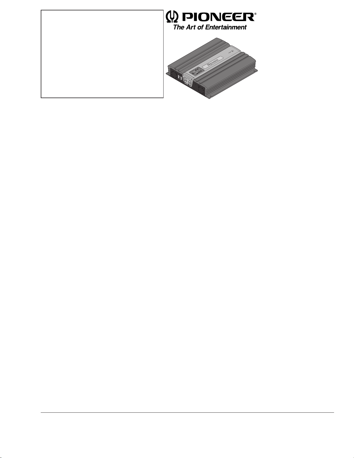
BRIDGEABLE POWER AMPLIFIER
PIONEER ELECTRONIC CORPORATION 4-1, Meguro 1-Chome, Meguro-ku, Tokyo 153-8654, Japan
PIONEER ELECTRONICS SERVICE INC. P.O.Box 1760, Long Beach, CA 90801-1760 U.S.A.
PIONEER ELECTRONIC [EUROPE] N.V. Haven 1087 Keetberglaan 1, 9120 Melsele, Belgium
PIONEER ELECTRONICS ASIACENTRE, PTE.LTD. 501 Orchard Road, #10-00, Wheelock Place, Singapore 238880
C PIONEER ELECTRONIC CORPORATION 1998
K-ZEB. FEB. 1998 Printed in Japan
GM-X822 X1R/UC
CONTENTS
1. SAFETY INFORMATION ............................................2
2. EXPLODED VIEWS AND PARTS LIST.......................3
3. SCHEMATIC DIAGRAM .............................................8
4. PCB CONNECTION DIAGRAM ................................12
5. ELECTRICAL PARTS LIST ........................................15
6. ADJUSTMENT..........................................................19
7. GENERAL INFORMATION .......................................20
7.1 IC .........................................................................20
7.2 DISASSEMBLY ...................................................21
7.3 BLOCK DIAGRAM ..............................................22
8. OPERATIONS AND SPECIFICATIONS.....................23
GM-X722 X1R/UC,ES,EW

2
GM-X822,X722
1. SAFETY INFORMATION
UC model
CAUTION
This service manual is intended for qualified service technicians; it is not meant for the casual do-it-yourselfer.
Qualified technicians have the necessary test equipment and tools, and have been trained to properly and safely repair
complex products such as those covered by this manual.
Improperly performed repairs can adversely affect the safety and reliability of the product and may void the warranty.
If you are not qualified to perform the repair of this product properly and safely; you should not risk trying to do so
and refer the repair to a qualified service technician.
W
ARNING
Lead in solder used in this product is listed by the California Health and Welfare agency as a known reproductive toxicant which may cause birth defects or other reproductive harm (California Health & Safety Code, Section 25249.5).
When servicing or handling circuit boards and other components which contain lead in solder, avoid unprotected skin
contact with the solder. Also, when soldering do not inhale any smoke or fumes produced.
3
GM-X822,X722
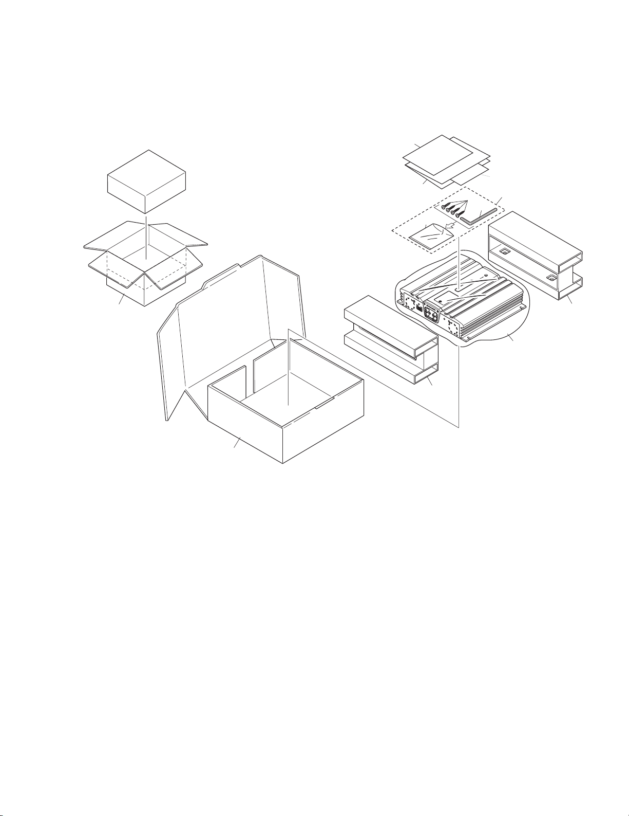
2. EXPLODED VIEWS AND PARTS LIST
2.1 PACKING
Fig. 1
10
11
9
2
1
4
3
7
8
5
8
6
4
GM-X822,X722
- PACKING SECTION PARTS LIST
Part No.
GM-X822 GM-X722
Mark No. Description X1R/UC X1R/UC X1R/ES X1R/EW
* 1 Screw Assy HEA0044 HEA0044 HEA0044 HEA0044
2 Screw(x4) BYC40P180FZK BYC40P180FZK BYC40P180FZK BYC40P180FZK
3 Polyethylene Bag HEG0011 HEG0011 HEG0011 HEG0011
4 Wrench HLP0001 HLP0001 HLP0001 HLP0001
5 Polyethylene Bag HEG0013 HEG0013 HEG0013 HEG0013
6 Carton HHG0164 HHG0165 HHG0166 HHG0167
7 Contain Box HHL0164 HHL0165 HHL0166 HHL0167
8 Protector(x2) HHP0025 HHP0025 HHP0025 HHP0025
9-1 Owner’s Manual HRD0060 HRD0061 HRD0062 HRD0063
9-2 Owner’s Manual Not used Not used HRD0069 Not used
10 Warranty Card *HRY1070 Not used Not used HRY1087
11 Card Not used ARY1048 Not used Not used
NOTE:
- Parts marked by “*”are generally unavailable because they are not in our Master Spare Parts List.
- Screws adjacent to ∇ mark on the product are used for disassembly.
- Owner's Manual
Model Part No. Language
GM-X822/X1R/UC HRD0060 English, French
GM-X722/X1R/UC HRD0061 English, French
GM-X722/X1R/ES HRD0062 English, Spanish
HRD0069 Arabic, Portuguese(B)
GM-X722/X1R/EW HRD0063 English, French, German, Dutch, Spanish, Italian
5
GM-X822,X722
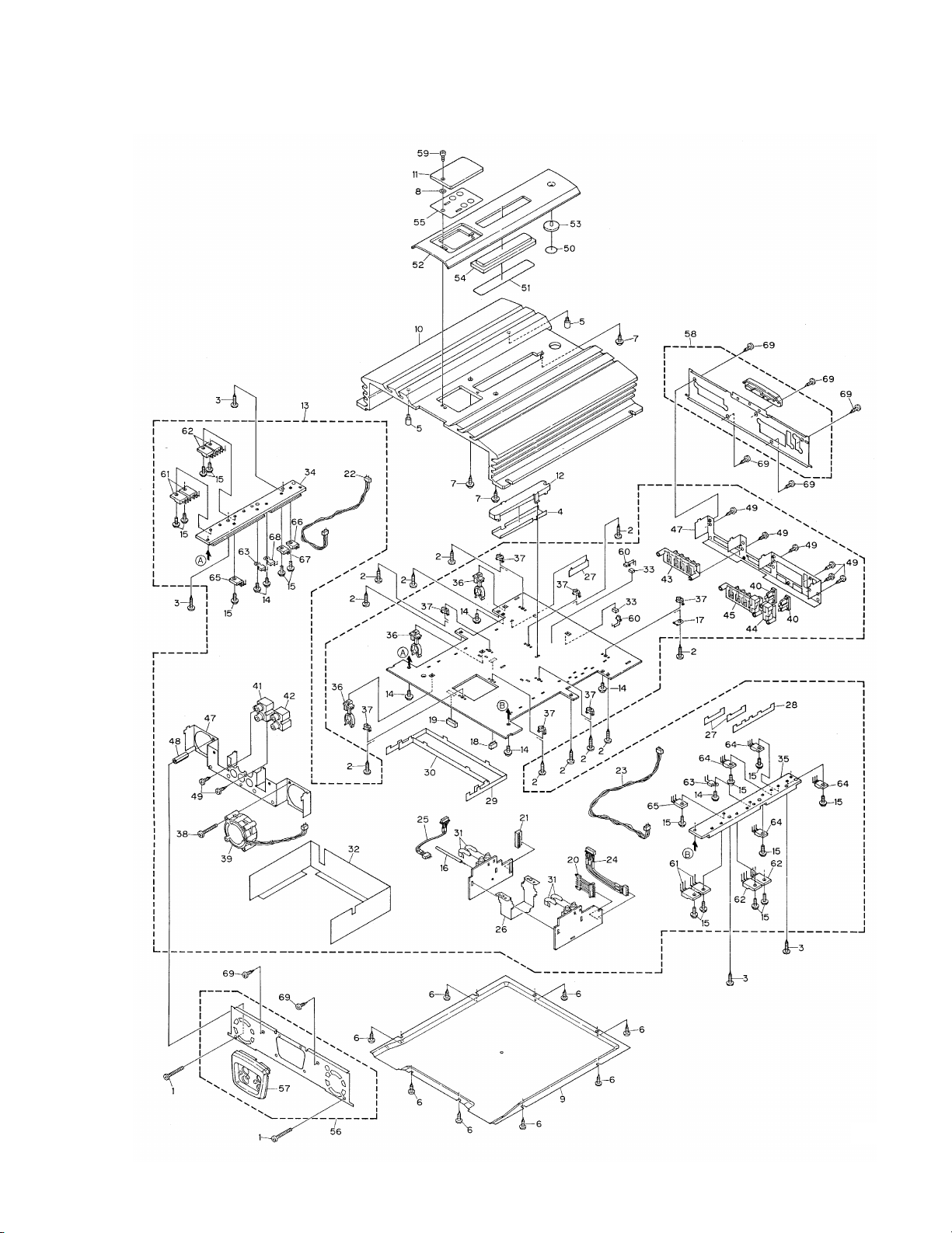
2.2 EXTERIOR
Fig. 2

6
GM-X822,X722
1 Screw BMZ30P250FZK
2 Screw(M3x12) CBA1323
3 Screw(M3x14) CBA1382
4 Sheet CNM5854
5 Screw HBA0006
6 Screw HBA0011
7 Screw HBA0012
8 Washer HBF0005
9 Case HNB0037
10 Heat Sink HNR0078
11 Window HNS0053
12 Lighting Conductor HNV0013
13 Amp Unit
See Contrast table(2)
14 Screw BMS30P060FZK
15 Screw BMS30P080FMC
16 Clamper CEF1009
17 Terminal(CN904) CKF1059
18 Plug(CN551) CKS1037
19 Plug(CN501) CKS1039
20 Connector(CN503) CKS3799
21 Connector(CN552) CKS3800
22 Cord(CN153) HDE5500
23 Cord(CN253) HDE5500
24 Cord(CN502) HDE5501
25 Cord(CN553) HDE5502
26 Holder HNC0029
27 Buss Bar HNC0043
28 Buss Bar HNC0045
29 Buss Bar HNC0051
30 Buss Bar HNC0053
31 Clip HNC0054
32 Separator HNM0047
33 Spacer
See Contrast table(2)
34 Heat Sink HNR0081
35 Heat Sink HNR0082
36 Clamper HNV0015
37 Spacer HNV3975
38 Screw BMZ30P250FZK
39 Fan Motor CXM1102
40 Fuse(20A) HEK0020
41 Pin Jack(CN801) HKB0002
42 Pin Jack(CN851) HKB0002
43 Terminal(CN101) HKE0010
44 Fuse Holder(CN902) HKE0012
45 Terminal(CN901) HKE0014
46 Holder HNC0027
47 Holder HNC0028
48 Spacer HNV0010
49 Screw PPZ30P060FZK
50 Film
See Contrast table(2)
51 Film See Contrast table(2)
52 Plate Unit See Contrast table(2)
53 Light Pipe Unit HXA0201
54 Plate Unit
See Contrast table(2)
55 Sheet Unit See Contrast table(2)
56 Panel Unit See Contrast table(2)
57 Plate HNS0066
58 Panel Unit
See Contrast table(2)
59 Screw SMZ30H080FCR
60 LED(D902,903)
See Contrast table(2))
61 Transistor
(Q113,114,213,214) 2SC5099
62 Transistor
(Q115,116,215,216) 2SA1907
63 Thermistor(TH651,652) CCX1013
64 FET(Q963-966) IRFIZ44N
65 Transistor(Q107,207) 2SC1568
66 Diode(D961) FML22S
67 Diode(D962) FML22R
68 Thermistor(TH901) CCX1027
69 Screw BSZ30P050FZK
(1) EXTERIOR SECTION PARTS LIST
Mark No. Description Part No.
Mark No. Description Part No.
7
GM-X822,X722
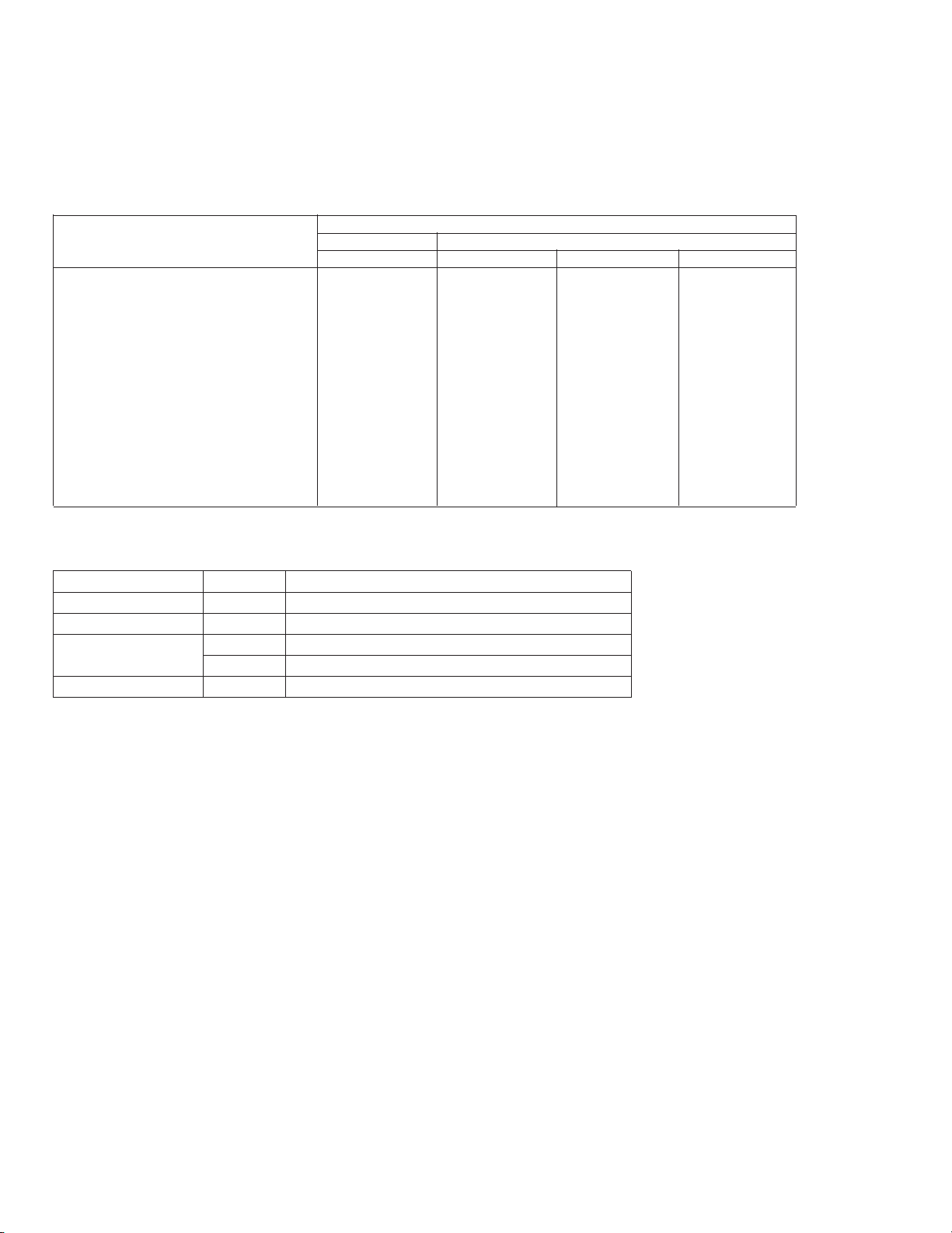
(2) CONTRAST TABLE
GM-X822/X1R/UC, GM-X722/X1R/UC, GM-X722/X1R/ES and GM-X722/X1R/EW are constructed the same except for the
following:
Part No.
GM-X822 GM-X722
Mark No. Symbol and Description X1R/UC X1R/UC X1R/ES X1R/EW
13 Amp Unit HWH0075 HWH0076 HWH0074 HWH0073
33 Spacer HNM0053(x2) HNM0053(x2) HNM0053(x1) HNM0053(x2)
50 Film CNM5856 Not used Not used Not used
51 Film CNM5855 Not used Not used Not used
52 Plate Unit HXA0115 HXA0111 HXA0111 HXA0111
54 Plate Unit HXA0206 HXA0203 HXA0203 HXA0203
55 Sheet Unit HXA0266 HXA0126 HXA0118 HXA0118
56 Panel Unit HXA0270 HXA0271 HXA0271 HXA0271
58 Panel Unit HXA0273 HXA0272 HXA0272 HXA0272
60 LED(D902,903) NSPWF50S(AQ) NSPWF50S(VQ) NSPWF50S(VQ) NSPWF50S(VQ)
GM-X822,X722
A
1
234
B
C
D
1
2
34
A
B C
AMP PCB
AUDIO PCB
BASS
PCB
AMP UNIT
AMP PCB
AUDIO PCB
BASS PCB
Consists of
-10dBs
-7.6dBs
-10.2dBs
30V
-30V
-35-30V
-35V
15.5V
-15.5V
3. SCHEMATIC DIAGRAM
3.1 AMP UNIT
Note: When ordering service parts, be sure to refer to "EXPLODED VIEWS AND PARTS LIST" or "ELECTRICAL PARTS
LIST".
8
A
9
GM-X822,X722
5
6
7
8
A
B
C
D
5
6
7
8
Fig. 3
A
-14.3dBs
21.3dBs
14.4V
14.4V
0.2V
14.3V
10.7V
0.2V
0V
5.0V
0V
0.3V
3.2V
0.1V
6.3V
3.5V
3.8V
1.9V
0.2V
2.6V
5.0V
5.0V
2.4V
2.4V
 Loading...