

Page 1

ENGLISH
ESPAÑOL
DEUTSCH
FRANÇAIS
ITALIANO
NEDERLANDS
BRIDGEABLE FOUR-CHANNEL POWER AMPLIFIER
AMPLIFICATEUR DE PUISSANCE PONTABLE A
QUATRE VOIES
Owner’s Manual
GM-X554
Mode d’emploi
Page 2

1
Contents
Before Using This Product ...................... 2
In case of trouble .............................................. 2
WARNING ........................................................ 2
Setting the Unit .......................................... 3
Gain Control ...................................................... 3
Input Select Switch ............................................ 3
Cut Off Frequency Control .............................. 3
Power Indicator ................................................ 4
BFC (Beat Frequency Control) Switch ............ 4
LPF (Low-Pass Filter)/HPF (High-Pass
Filter) Select Switch .................................. 4
Connecting the Unit .................................. 5
Connection Diagram ........................................ 6
Connecting the Power Terminal ........................ 7
Connecting the Speaker Terminals .................. 8
Connecting the Speakers and Input wires ........ 9
Installation ................................................ 11
Example of installation on the floor mat
or on the chassis ...................................... 11
Specifications .......................................... 12
Page 3

Before Using This Product
2
ENGLISH ESPAÑOL DEUTSCH FRANÇAIS
ITALIANO NEDERLANDS
Thank you for purchasing this PIONEER
product. Before attempting operation, be
sure to read this manual.
In case of trouble
When the unit does not operate properly,
contact your dealer or the nearest authorized PIONEER Service Station.
WARNING
• Always use the special red battery and ground
wire [RD-223], which is sold separately. Connect
the battery wire directly to the car battery positive
terminal (+) and the ground wire to the car body.
• Do not touch the amplifier with wet hands.
Otherwise you may get an electric shock. Also,
do not touch the amplifier when it is wet.
• For traffic safety and to maintain safe driving
conditions, keep the volume low enough so that
you can still hear normal traffic sound.
• Check the connections of the power supply and
speakers if the fuse of the separately sold battery
wire or the amplifier fuse blows. Detect the cause
and solve the problem, then replace the fuse with
another one of the same size and rating.
• To prevent malfunction of the amplifier and
speakers, the protective circuit will cut the power
supply to the amplifier (sound will stop) when an
abnormal condition occurs. In such a case, switch
the power to the system OFF and check the
connection of the power supply and speakers.
Detect the cause and solve the problem.
• Contact the dealer if you cannot detect the cause.
• To prevent an electric shock or short-circuit
during connection and installation, be sure to
disconnect the negative (–) terminal of the battery
beforehand.
• Confirm that no parts are behind the panel when
drilling a hole for installation of the amplifier. Be
sure to protect all cables and important equipment
such as fuel lines, brake lines and the electrical
wiring from damage.
This product complies with the EMC
Directives (89/336/EEC, 92/31/EEC)
and CE Marking Directive (93/68/EEC).
Page 4
3
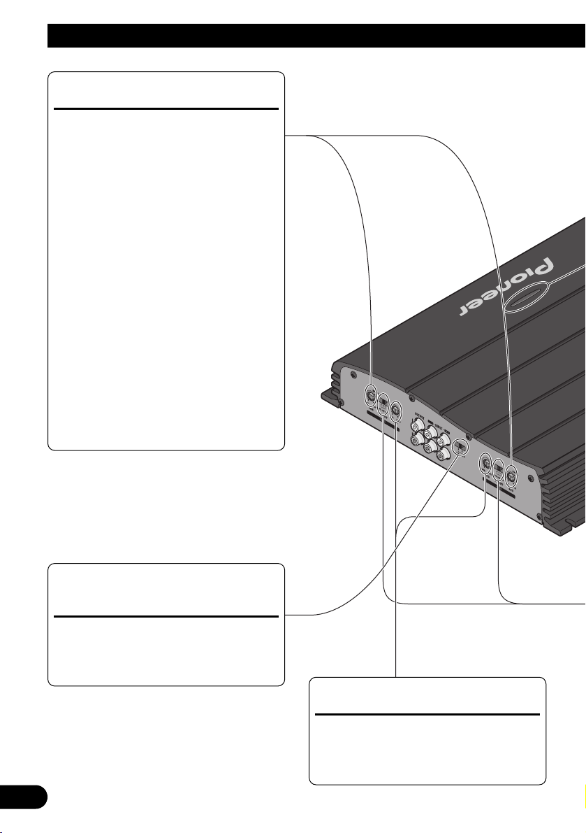
Setting the Unit
Gain Control
Adjusting the gain controls A and B will
help match the output of the car stereo
to the Pioneer amplifier. Normally, set
the gain controls to the “NORMAL”
position. If the output is low, even when
the volume of the car stereo is turned
up, turn these controls clockwise. If
there is distortion when the volume of
the car stereo is turned up, turn these
controls counter-clockwise.
• If you only use one input plug, set the gain
controls for speaker outputs A and B to the
same position.
• When using with an RCA equipped car
stereo (standard output of 500 mV), set to
the NORMAL position. When using with
an RCA equipped Pioneer car stereo with
max. output of 4 V or more, adjust level to
match the car stereo output level.
Cut Off Frequency Control
If the LPF/HPF select switch is set to
LPF or HPF, you can select a cut off
frequency from 40 to 120 Hz.
Input Select Switch
For two-channel input, slide this switch
to the left. For four-channel input, slide
this switch to the right.
Page 5
4
ENGLISH ESPAÑOL DEUTSCH FRANÇAIS
ITALIANO NEDERLANDS
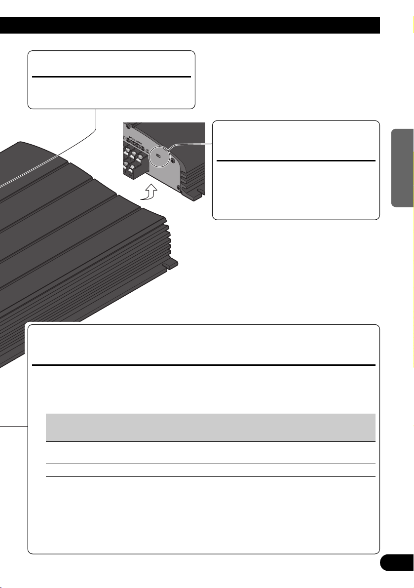
Power Indicator
The power indicator lights when the
power is switched on.
BFC (Beat Frequency Control) Switch
If you hear a beat while listening to an
MW/LW broadcast with your car stereo,
change the BFC switch using a small
standard tip screwdriver.
LPF (Low-Pass Filter)/HPF (High-Pass Filter) Select Switch
Set the LPF/HPF select switch as follows according to the type of speaker that is connected
to the speaker output connector and the car stereo system:
LPF/HPF Select Audio frequency range Speaker Remarks
Switch to be output Type
LPF (Left) * — 40 to 120 Hz Subwoofer Connect a subwoofer.
OFF (Center) Full range Full range
HPF (Right) * 40 to 120 Hz — Full range Use if you want to cut the
very low frequency range*
because it is not necessary
for the speakers you are
using.
* See the “Cut Off Frequency Control” section.
Page 6
5
Connecting the Unit
CAUTION
• Disconnect the negative (–) terminal of the battery to avoid the risk of short-circuit and damage
to the unit.
• Secure the wiring with cable clamps or adhesive
tape. To protect the wiring, wrap adhesive tape
around it where they lie against metal parts.
• Do not route wires where they will get hot, for
example where the heater will blow over them. If
the insulation heats up, it may become damaged,
resulting in a short-circuit through the vehicle
body.
• Make sure that wires will not interfere with moving parts of the vehicle, such as the gearshift,
handbrake or seat sliding mechanism.
• Do not shorten any wires. Otherwise the protection circuit may fail to work when it should.
• Never feed power to other equipment by cutting
the insulation of the power supply wire to tap
from the wire. The current capacity of the wire
will be exceeded, causing overheating.
Speaker Channel Speaker Type Power
Four-channel
Subwoofer Nominal input: Min. 60 W
Other than subwoofer Max. input: Min. 100 W
Two-channel
Subwoofer Nominal input: Min. 155 W
Other than subwoofer Max. input: Min. 240 W
Three-channel Subwoofer Nominal input: Min. 60 W
Speaker output A Other than subwoofer Max. input: Min. 100 W
Three-channel Subwoofer Nominal input: Min. 155 W
Speaker output B Other than subwoofer Max. input: Min. 240 W
To prevent damage
• Do not ground the speaker wire directly or connect a negative (–) lead wire for several speakers.
• This unit is for vehicles with a 12-volt battery and
negative grounding. Before installing it in a recreational vehicle, truck or bus, check the battery
voltage.
• If the car stereo is kept on for a long time while
the engine is at rest or idling, the battery may go
dead. Turn the car stereo off when the engine is at
rest or idling.
• If the system remote control wire of the amplifier
is connected to the power terminal through the
ignition switch (12 V DC), the amplifier will
always be on when the ignition is on— regardless
of whether the car stereo is on or off. Because of
this, the battery could go dead if the engine is at
rest or idling.
• Speakers to be connected to the amplifier should
conform with the standards listed below. If they
do not conform, they may catch fire, emit smoke
or become damaged. The speaker impedance
must be 2 to 8 ohms. But in case of two-channel
and other bridge connections, the speaker
impedance must be 4 to 8 ohms.
• Install and route the separately sold battery wire
as far away as possible from the speaker wires.
Install and route the separately sold battery wire,
ground wire, speaker wires and the amplifier as
far away as possible from the antenna, antenna
cable and tuner.
• Cords for this product and those for other products may be different colors even if they have the
same function. When connecting this product to
another product, refer to the supplied Installation
manuals of both products and connect cords that
have the same function.
Page 7
6
ENGLISH ESPAÑOL DEUTSCH FRANÇAIS
ITALIANO NEDERLANDS
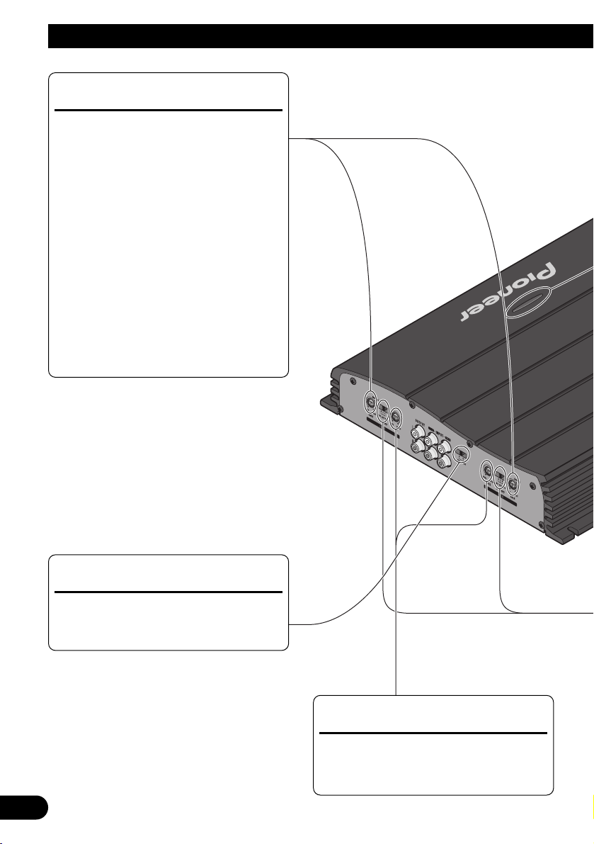
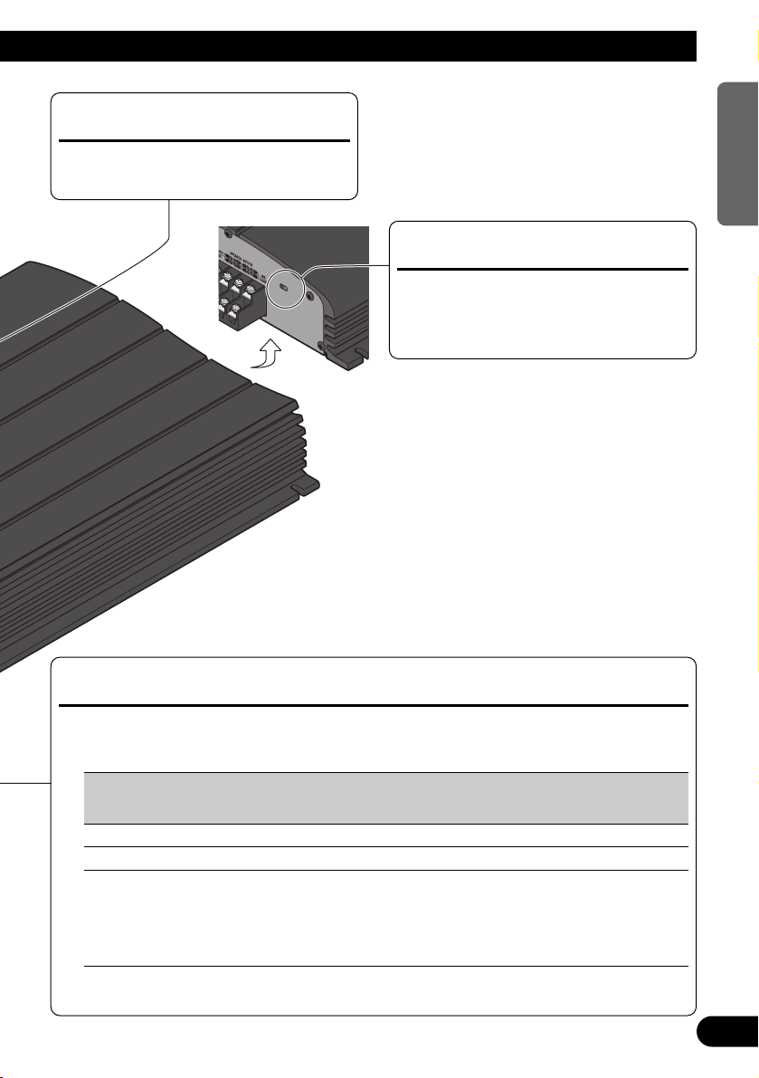
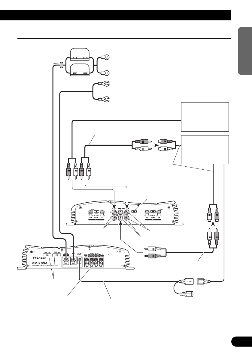
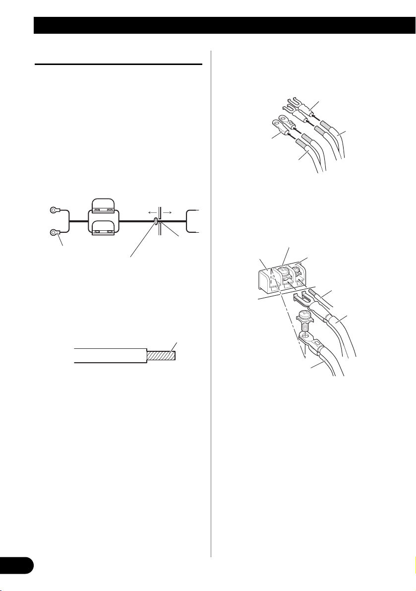
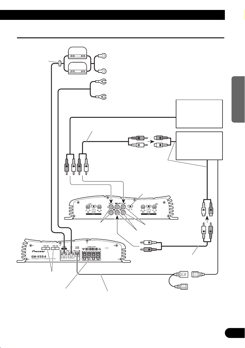
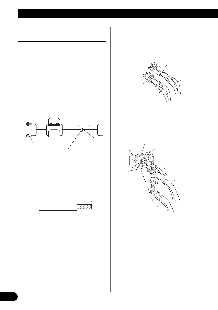
Connection Diagram
Grommet
RCA input
Special red battery wire [RD-223] (sold separately)
After making all other connections at the amplifier,
connect the battery wire terminal of the amplifier to
the positive (+) terminal of the battery.
Ground wire (Black) [RD-223] (sold separately)
Connect to metal body or chassis.
Amplifier with
RCA input jacks
Car stereo with
RCA output jacks
System remote control wire (sold separately)
Connect the male terminal of this wire to the system remote control
terminal of the car stereo (SYSTEM REMOTE CONTROL). The female
terminal can be connected to the auto-antenna relay control terminal. If the
car stereo does not have a system remote control terminal, connect the
male terminal to the power terminal through the ignition switch.
Fuse (30 A)
Fuse (30 A)
Connecting wires with RCA pin
plugs (sold separately).
Connecting wires with RCA pin
plugs (sold separately).
Speaker terminal
See the “Connecting the
Speakers and Input wires”
section for speaker connection instructions.
Fuse (20 A) × 2
External Output
If only one input plug is used, do not
connect anything to RCA input jack B.
RCA input jack BRCA output jack
Front side
RCA input jack A
Back side
Input Select Switch
For two-channel input, slide this switch
to the left. For four-channel input, slide
this switch to the right.
Page 8
7
Connecting the Unit
Connecting the Power Terminal
• Always use the special red battery and ground
wire [RD-223], which is sold separately. Connect
the battery wire directly to the car battery positive
terminal (+) and the ground wire to the car body.
1. Pass the battery wire from the
engine compartment to the interior
of the vehicle.
• After making all other connections to the
amplifier, connect the battery wire terminal
of the amplifier to the positive (+) terminal of
the battery.
2. Twist the battery wire, ground wire
and system remote control wire.
3. Attach lugs to wire ends. Lugs not
supplied.
• Use pliers, etc., to crimp lugs to wires.
4. Connect the wires to the terminal.
• Fix the wires securely with the terminal
screws.
Engine
compartment
Interior of
the vehicle
Drill a 14 mm
hole into the
vehicle body.
Insert the O-ring rubber
grommet into the vehicle
body.
Positive terminal
GND terminal
Power terminal
Battery wire
System remote
control terminal
System remote
control wire
Ground wire
Twist
Battery wire
Ground wire
Lug
Lug
Fuse (30 A)
Fuse (30 A)
Page 9
8
ENGLISH ESPAÑOL DEUTSCH FRANÇAIS
ITALIANO NEDERLANDS
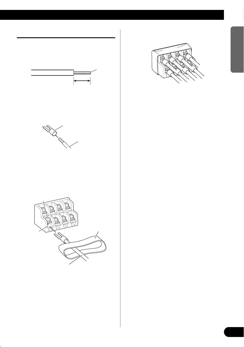
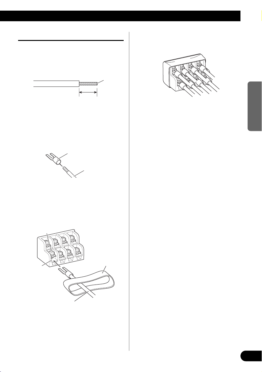
Connecting the Speaker Terminals
1. Expose the end of the speaker wires
using nippers or a cutter by about
10 mm and twist.
2. Attach lugs to speaker wire ends.
Lugs not supplied.
• Use pliers, etc., to crimp lugs to wires.
3. Connect the speaker wires to the
speaker terminals.
• Connect the speaker wires, passing them
through the terminal cover.
• Fix the speaker wires securely with the termi-
nal screws.
4. Push on the terminal cover.
10 mm
Twist
Speaker wire
Lug
Speaker
terminal
Terminal cover
Terminal screw
Speaker wire
Page 10
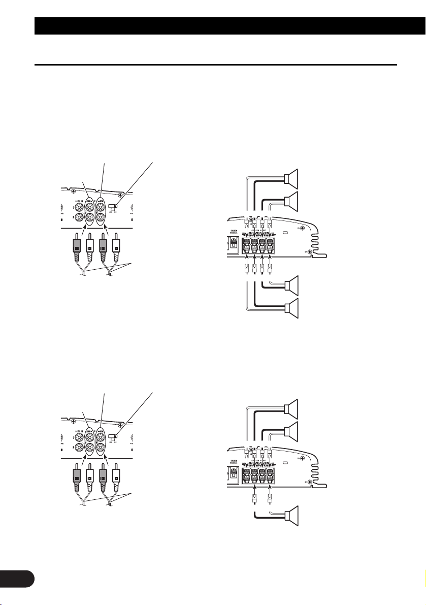
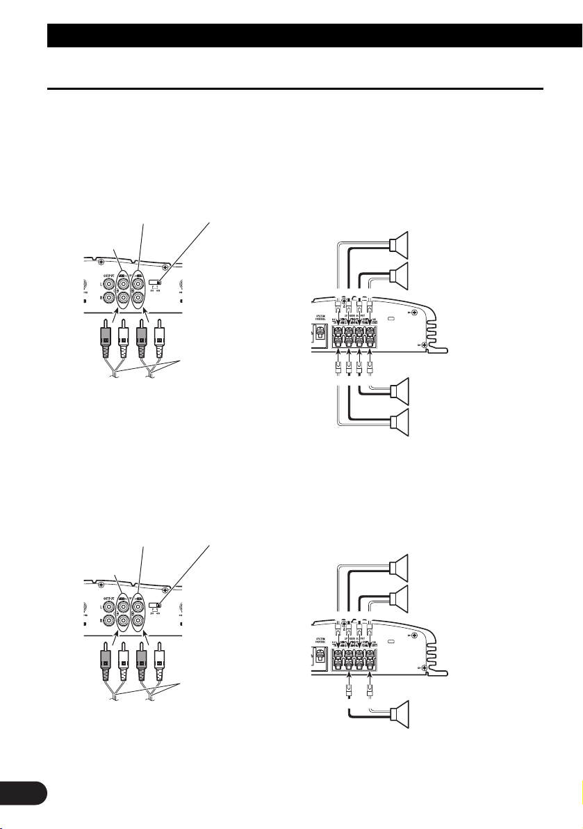
Connecting the Speakers and Input wires
The speaker output mode can be four-channel, three-channel (stereo +
mono) or two-channel (stereo, mono). Connect the speaker leads to suit the
mode according to the figures shown below.
Four-channel mode
Three-channel mode
+
+
≠
+
≠
≠
+
+
≠
+
+
≠
≠
≠
9
Connecting the Unit
Input Select Switch
For two-channel input, slide this switch to
the left. For four-channel input, slide this
switch to the right.
RCA input jack A
(Left)
Speaker out A
(Right)
RCA input jack B
Connecting wires
with RCA plugs (sold
separately)
From car stereo (RCA output)
If only one input plug is used, such as when the
car stereo has only one output (RCA output),
connect the plug to RCA input jack A, but do
not connect a plug to RCA input jack B.
(Right)
Speaker out B
(Left)
Input Select Switch
For two-channel input, slide this switch to
the left. For four-channel input, slide this
switch to the right.
RCA input jack A
(Left)
Speaker out A
(Right)
RCA input jack B
Connecting wires
with RCA plugs (sold
separately)
From car stereo (RCA output)
If only one input plug is used, such as when the
car stereo has only one output (RCA output),
connect the plug to RCA input jack A, but do
not connect a plug to RCA input jack B.
Speaker out B
(Mono)
Page 11
10
ENGLISH ESPAÑOL DEUTSCH FRANÇAIS
ITALIANO NEDERLANDS
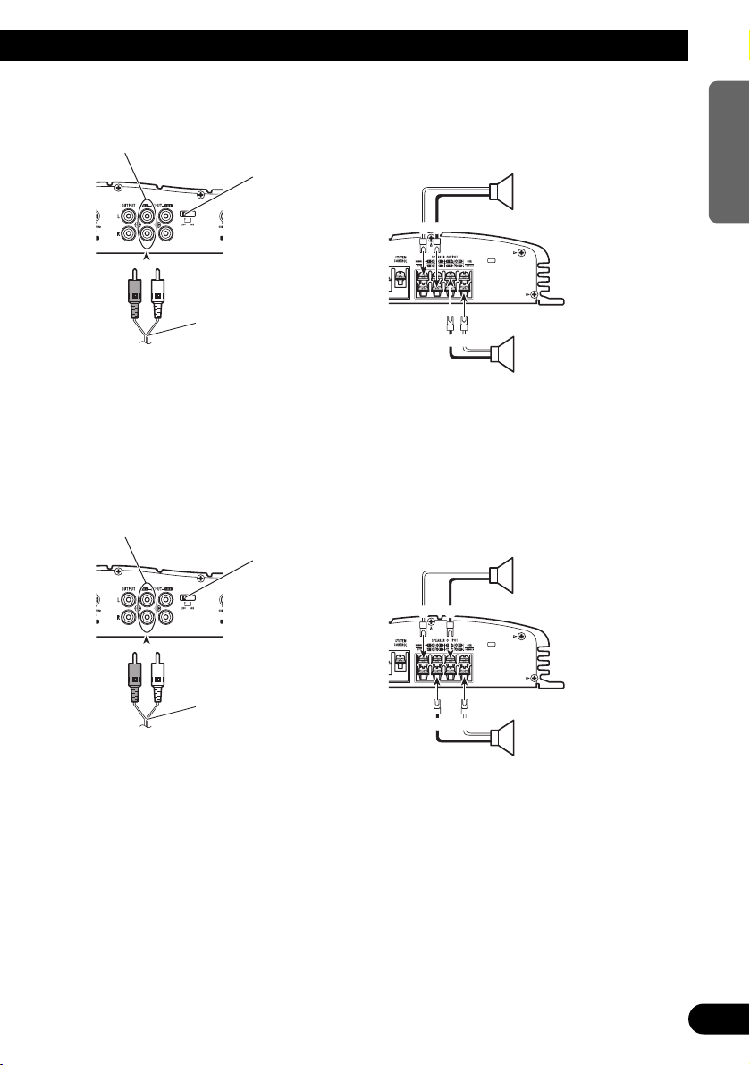
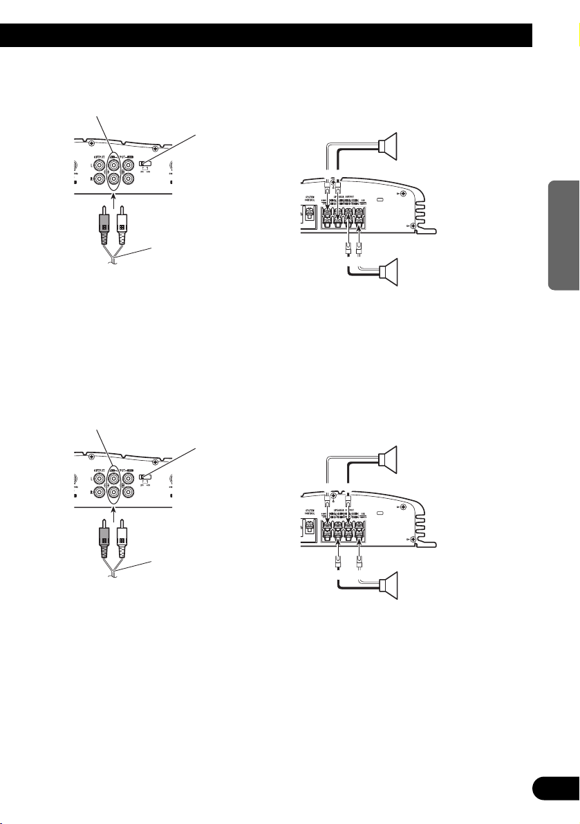
Two-channel mode (Stereo)
Two-channel mode (Mono)
+
+
≠
≠
+
+
≠
≠
RCA input jack A
Speaker (Left)
Speaker (Right)
Connecting wire with RCA
plugs (sold separately)
From car stereo (RCA output)
Input Select Switch
Slide this switch to the left.
RCA input jack A
Speaker (Mono)
Speaker (Mono)
Connecting wire with RCA
plugs (sold separately)
From car stereo (RCA output)
Input Select Switch
Slide this switch to the left.
Page 12
11
Installation
CAUTION
• Do not install in:
—Places where it could injure the driver or pas-
sengers if the vehicle stops suddenly.
—Places where it may interfere with the driver,
such as on the floor in front of the driver’s
seat.
• Make sure that wires are not caught in the sliding
mechanism of the seats, resulting in a short-circuit.
• Confirm that no parts are behind the panel when
drilling a hole for installation of the amplifier.
Protect all cables and important equipment such
as fuel lines, brake lines and electrical wiring
from damage.
• Install tapping screws in such a way that the
screw tip does not touch any wire. This is important to prevent wires from being cut by vibration
of the car, which can result in fire.
• To prevent electric shock, do not install the ampli-
fier in places where it might come in contact with
liquids.
• To ensure proper installation, use the supplied
parts in the manner specified. If any parts other
than the supplied ones are used, they may damage
internal parts of the amplifier, or they may
become loose causing the amplifier to shut down.
To prevent malfunction
• To ensure proper heat dissipation of the amplifier,
be sure of the following during installation.
—Allow adequate space above the amplifier for
proper ventilation.
—Do not cover the amplifier with a floor mat or
carpet.
• Do not install the amplifier near a door where it
may get wet.
• Do not install the amplifier on unstable places
such as the spare tire board.
• The best location for installation differs with the
car model and installation location. Secure the
amplifier at a sufficiently rigid location.
• Make temporary connections first and check that
the amplifier and the system operate properly.
• After installing the amplifier, confirm that the
spare tire, jack and tools can be easily removed.
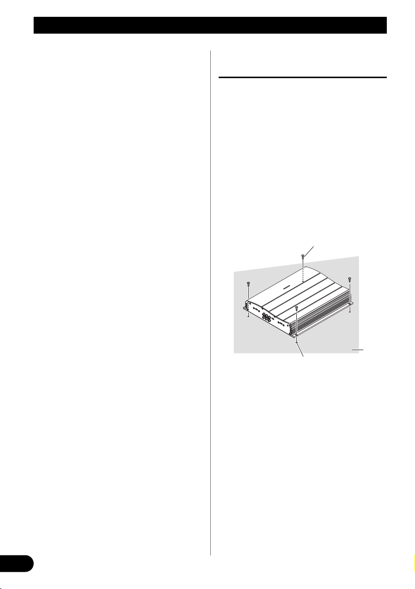
Example of installation on the floor
mat or on the chassis
1. Place the amplifier where it is to be
installed. Insert the supplied tapping screws (4 × 18 mm) into the
screw holes. Push on the screws with
a screwdriver so they make marks
where the installation holes are to
be located.
2. Drill 2.5 mm diameter holes at the
point marked, and install the amplifier, either on the carpet or directly
to the chassis.
Drill a 2.5 mm diameter hole
Tapping-screws
(4 × 18 mm)
Floor mat
or chassis
Page 13

Specifications
Power source .......................................................................................................... 14.4 V DC (10.8 — 15.1 V allowable)
Grounding system .......................................................................................................................................... Negative type
Current consumption .................................................................................................... 27.1 A (at continuous power, 4 Ω)
Average current drawn* ........................................................................................................ 9.1 A (4 Ω for four channels)
14.5 A (4 Ω for two channels)
Fuse ........................................................................................................................................................................ 20 A × 2
Dimensions ...................................................................................................................... 279 (W) × 58 (H) × 324 (D) mm
Weight .................................................................................................................... 4.8 kg (Leads for wiring not included)
Maximum power output .................................................................................................................. 100 W × 4 / 240 W × 2
Continuous power output ........................................................................ 75 W × 4 / 200 W × 2 (DIN45324, +B=14.4 V)
Load impedance .......................................................................................................................... 4 Ω (2 — 8 Ω allowable)
(Bridge connection: 4 — 8 Ω allowable)
Frequency response .......................................................................................................... 10 — 50,000 Hz (+0 dB, –1 dB)
Signal-to-noise ratio .................................................................................................................... 100 dB (IEC-A network)
Distortion ........................................................................................................................................ 0.008% (10 W, 1 kHz)
Separation ...................................................................................................................................................... 65 dB (1 kHz)
Low pass filter ................................................................................................................ Cut off frequency: 40 — 120 Hz
Cut off slope: –12 dB/oct
High pass filter ................................................................................................................ Cut off frequency: 40 — 120 Hz
Cut off slope: –12 dB/oct
Maximum input level/impedance .................................................................................. RCA: 6.5 V/22 kΩ (0.4 — 6.5 V)
Note:
• Specifications and the design are subject to possible modification without notice
due to improvements.
*Average current drawn
• The average current drawn is nearly the maximum current drawn by this unit
when an audio signal is input. Use this value when working out total current
drawn by multiple power amplifiers.
12
ENGLISH ESPAÑOL DEUTSCH FRANÇAIS
ITALIANO NEDERLANDS
Page 14

1
Contenido
Antes de usar este producto .................... 2
En caso de desperfectos .................................... 2
ADVERTENCIA .............................................. 2
Ajuste de esta unidad .............................. 3
Control de ganancia .......................................... 3
Interruptor de selección de entrada .................. 3
Control de frecuencia de corte .......................... 3
Indicador de alimentación ................................ 4
Interruptor BFC (Control de la frecuencia de
batido) ........................................................ 4
Interruptor de selección LPF (Filtro de paso
bajo)/HPF (Filtro de paso alto) .................. 4
Conexión de la unidad .............................. 5
Diagrama de conexión ...................................... 6
Conexión del terminal de alimentación ............ 7
Conexión del terminal de altavoz ...................... 8
Conexión de los altavoces y cables
de entrada .................................................. 9
Instalación ................................................ 11
Ejemplo de instalación en la alfombra del
piso o en el chasis .................................... 11
Especificaciones .................................... 12
Page 15

Antes de usar este producto
2
ENGLISH
ESPAÑOL DEUTSCH FRANÇAIS
ITALIANO NEDERLANDS
Muchas gracias por la adquisición de este
producto PIONEER. Antes de tratar de
operarlo, lea atentamente este manual.
En caso de desperfectos
Si esta unidad no funciona correctamente,
póngase en contacto con su distribuidor o
con el Centro de Servicio PIONEER
autorizado más cercano.
ADVERTENCIA
• Siempre utilice el cable de batería rojo especial y
el cable de tierra [RD-223], vendidos separadamente. Conecte el cable de batería directamente
al terminal positivo de la batería del vehículo (+)
y el cable de tierra a la carrocería del vehículo.
• No toque en el amplificador con las manos
mojadas. Caso contrario, usted puede llevar un
choque eléctrico. Igualmente, no toque en el
amplificador cuando esté mojado.
• Para seguridad del tráfico y para mantener condiciones de conducción seguras, mantenga el volumen suficientemente bajo de manera que aun se
pueda escuchar el sonido del tráfico normal.
• Verifique las conexiones del suministro de
energía y altavoces para ver si el fusible del cable
de batería vendido separadamente o el fusible del
amplificador se queman. Detecte la causa y solucione el problema, y reemplace el fusible con un
otro del mismo tamaño y régimen.
• Para evitar mal funcionamiento del amplificador
y altavoces, el circuito de protección cortará la
alimentación al amplificador (el sonido se
detendrá) cuando se produzca una situación anormal. En tal caso, apague el sistema y verifique la
conexión de la alimentación y altavoces. Detecte
la causa y resuelva el problema.
• Contacte a su distribuidor si no puede detectar la
causa.
• Para evitar choques eléctricos o cortocircuitors
durante la conexión e instalación, asegúrese de
desconectar el terminal negativo (–) de la batería
antes de proceder.
• Confirme que ninguna parte quede detrás del
panel, cuando perfore un orificio para la instalación del amplificador. Asegúrese de proteger
todos los cables y equipos importantes, tales
como líneas de combustibles, líneas de frenos y el
cableado eléctrico.
Este producto cumple con las Directivas
EMC (89/336/CEE, 92/31/CEE) y
Directiva de Marcación CE
(93/68/CEE).
Page 16
3
Ajuste de esta unidad
Control de ganancia
El ajuste de los controles de ganancia A
y B le ayuda a igualar la salida del
equipo estéreo para automóvil al amplificador Pioneer. Normalmente, ajuste
los controles de ganancia a la posición
“NORMAL”. Si la potencia de salida
está baja aún cuando se aumenta el volumen del equipo estéreo del automóvil,
gire esos controles a la derecha. Si se
produce distorsión cuando se aumenta el
volumen del equipo estéreo de
automóvil, gire los controles a la
izquierda.
• Si se usa solamente un enchufe de entrada,
ajuste los controles de ganancia para las
salidas de altavoz A y B a la misma posición.
• Cuando se usa un estéreo de automóvil
equipado con RCA (salida estándar de
500 mV), ajuste a la posición NORMAL.
Cuando use con un estéreo de automóvil
Pioneer equipado con RCA con una salida
máxima de 4 V o más, ajuste el nivel para
adecuarse al nivel de salida del estéreo del
automóvil.
Control de frecuencia de corte
Si se ajusta el interruptor de selección
LPF/HPF a LPF o HPF, se puede seleccionar una frecuencia de corte de 40 a
120 Hz.
Interruptor de selección de
entrada
Para la entrada de dos canales, deslice
este interruptor hacia la izquierda. Para
la entrada de cuatro canales, deslice este
interruptor hacia la derecha.
Page 17
4
ENGLISH
ESPAÑOL DEUTSCH FRANÇAIS
ITALIANO NEDERLANDS
Indicador de alimentación
El indicador de alimentación se ilumina
cuando la unidad se encuentra activada.
Interruptor BFC (Control de la
frecuencia de batido)
Si escucha sonidos de batido mientras
está recibiendo una emisora de MW/LW
con su estéreo de automóvil, cambie el
interruptor BFC usando un
destornillador pequeño.
Interruptor de selección LPF (Filtro de paso bajo)/HPF (Filtro de paso
alto)
Ajuste el interruptor de selección LPF/HPF de la manera siguiente, de acuerdo al tipo de
altavoz que se encuentra conectado al conector de salida de altavoz y al sistema estéreo de
automóvil:
Interruptor de Gama de frecuencia Tipo de Observaciones
selección LPF/HPF de audio a ser generada altavoz
LPF (izquierda) * — 40 a 120 Hz Altavoz de graves Conecte a un altavoz
secundario de graves secundario.
OFF (central) Gama completa Gama completa
HPF (derecha) * 40 a 120 Hz — Gama completa Utilice si desea cortar la
gama de frecuencia*
muy baja debido a que
no es necesaria para el
altavoz que está usando.
* Consulte a “Control de frecuencia de corte”.
Page 18

5
Conexión de la unidad
PRECAUCION
• Quite el terminal negativo (–) de la batería para
evitar riesgo de cortocircuitos y daño a la unidad.
• Asegure el alambrado con abrazaderas de cable o
cinta adhesiva. Para proteger el alambrado,
envuelva cinta adhesiva alrededor de ellos en
donde contacta con partes metálicas.
• No tienda cables por donde puedan calentarse,
por ejemplo donde el calentador sople sobre ellos.
Si la aislación se calienta, podría resultar dañada,
resultando en cortocircuito a través de la carrocería del vehículo.
• Asegúrese que los alambres no interfieran con
partes móviles del vehículo como la palanca de
cambios, el freno de mano o el mecanismo de
deslizamiento de los asientos.
• No corte ningún cable. De otra manera, el circuito
de protección podría no funcionar cuando
debiera.
• Nunca alimente otro equipo cortando la aislación
del cable de alimentación y conectándolo al
cable. La capacidad de corriente del cable será
excedida, causando sobrecalentamiento.
Canal de altavoces
Tipo de altavoz Alimentación
Cuatro canales
Altavoz de graves secundario Entrada nominal: 60 W mín.
Diferente a un altavoz de graves secundario Entrada máxima: 100 W mín.
Dos canales
Altavoz de graves secundario Entrada nominal: 155 W mín.
Diferente a un altavoz de graves secundario Entrada máxima: 240 W mín.
Salida de altavoz A Altavoz de graves secundario Entrada nominal: 60 W mín.
de tres canales Diferente a un altavoz de graves secundario Entrada máxima: 100 W mín.
Salida de altavoz B Altavoz de graves secundario Entrada nominal: 155 W mín.
de tres canales Diferente a un altavoz de graves secundario Entrada máxima: 240 W mín.
Para prevenir de daños
• No conecte a tierra (masa) el cable del altavoz
directamente ni conecte un cable negativo (–) a
varios altavoces.
• Esta unidad es para vehículos con una batería de
12 voltios y terminal negativo a tierra. Antes de
instalar en un vehículo de recreación, camión u
ómnibus, verifique el voltaje de la batería.
• Si el sistema estereofónico del coche está funcionando por un largo período de tiempo mientras el
motor permanece inactivo o en marcha al ralentí,
la batería puede agotarse. Apague el estéreo de
automóvil cuando el motor se encuentre funcionando en marcha al ralenté o permanece in activo.
• Si el cable del control remoto de sistema del
amplificador se conecta al terminal de alimentación a través del interruptor de encendido
(12 V de CC), el amplificador estará siempre activado cuando el encendido está activado, sin considerar de si el estéreo de automóvil se encuentra
activado o desactivado. Debido a esto, la batería
puede agotarse si deja el motor funcionando en
marcha al ralentí o permanece inactivo.
• Los altavoces a ser conectados al amplificador
deben estar conforme con las normas listadas
debajo. Si no cumplen con las normas, pueden
combustionar, emitir humos o dañarse. El
impedimiento altavoz debe estar de 2 a 8 ohms,
pero en caso de que dos canales y otros puentes
contecten, el impedimiento de altavoz debe ester
de 4 a 8 ohms.
• Instale y coloque el cable de batería vendido separadamente lo más alejado posible de los cables
de los altavoces. Instale y coloque el cable de
batería y cable de tierra vendidos separadamente,
los cables de los altavoces, y el amplificador lo
más alejados posible de la antena, cable de antena
y sintonizador.
• Los cables para esta unidad y aquéllas para las
unidades pueden ser de colores diferentes aun si
tienen la misma función. Cuando se conecta esta
unidad a otra, refiérase a los manuales de instalación de ambas unidades y conecte los cables
que tienen la misma función.
Page 19
6
ENGLISH
ESPAÑOL DEUTSCH FRANÇAIS
ITALIANO NEDERLANDS
Diagrama de conexión
Ojal
Entrada RCA
Cable de batería rojo especial [RD-223]
(en venta por separado)
Después de realizar todas las conexiones al amplificador,
conecte el terminal del conductor de batería del amplificador
al terminal positivo (+) de la batería.
Cable de puesta a tierra (negro) [RD-223]
(en venta por separado)
Conecte a una carrocería metálica o chasis.
Amplificador con
tomas con conector
de entrada RCA
Estéreo de automóvil
con tomas con
conector de salida
RCA
Tomas de conector
de salida RCA
Cable del control remoto del sistema (en venta por separado)
Conecte el terminal macho de este hilo al terminal de control remoto
de sistema del equipo estéreo para automóvil (SYSTEM REMOTE
CONTROL). El terminal hembra puede ser conectado al terminal de
control del relé de antena. Si el estéreo de automóvil no tiene un
terminal de control remoto del sistema, conecte el terminal macho al
terminal de alimentación a través del interruptor de encendido.
Fusible (30 A)
Fusible (30 A)
Lado delantero
Conexión de cables con los enchufes de conector
RCA (en venta por separado).
Conexión de cables con los enchufes de
conector RCA (en venta por separado).
Salida externa
Si se usa solamente un enchufe de entrada, no conecte nada a la toma de entrada
RCA B.
Terminal de altavoz
Vea la sección “Conexión de
los altavoces y cables de
entrada” para las instrucciones
de conexión del altavoz.
Fusible (20 A)
× 2
Interruptor de selección de entrada
Para la entrada de dos canales, deslice
este interruptor hacia la izquierda. Para la
entrada de cuatro canales, deslice este
interruptor hacia la derecha.
Tomas de conector de
entrada RCA B
Tomas de conector de entrada RCA A
Lado trasero
Page 20
7
Conexión de la unidad
Conexión del terminal de
alimentación
• Siempre utilice el cable de batería rojo especial y
el cable de tierra [RD-223], vendidos separadamente. Conecte el cable de batería directamente
al terminal positivo de la batería del vehículo (+)
y el cable de tierra a la carrocería del vehículo.
1. Pase el cable de batería desde el
compartimiento del motor al interior del vehículo.
• Luego de hacer todas las otras conexiones al
amplificador, conecte el terminal del conductor de batería del amplificador al terminal
positivo (+) de la bateria.
2. Tuerza el cable de batería, cable de
puesta a tierra y cable de control
remoto del sistema.
3. Fije las orejetas a los extremos de
los cables. Orejetas no suministrados.
• Utilice alicates, etc. para plegar las orejetas a
los cables.
4. Conecte los cables al terminal.
• Fijar los cables firmemente utilizando los
tornillos para terminales.
Fusible (30 A)
Compartimiento del
motor
Interior del
vehículo
Perfore un orificio de 14 mm en
la carrocería del
vehículo.
Inserte el ojal de caucho
de la junta tórica en la
corrocería del vehículo.
Terminal positivo
Fusible (30 A)
Terminal GND
Terminal
POWER
Cable de batería
Terminal de control
remoto del sistema
Cable del control
remoto del sistema
Cable de puesta
a tierra
Cable de batería
Cable de
puesta a tierra
Tuérzala
Orejeta
Orejeta
Page 21
8
ENGLISH
ESPAÑOL DEUTSCH FRANÇAIS
ITALIANO NEDERLANDS
Conexión del terminal de altavoz
1. Desnude la extremidad de los cables
de altavoces utilizando alicates o
una tajadera por aproximadamente
10 mm y tuérzala.
2. Fije las orejetas a los extremos de
los cables de altavoz. Orejetas no
suministrados.
• Utilice alicates, etc. para plegar las orejetas a
los cables.
3. Conecte los cables de altavoz al terminal de altavoz.
• Conecte los hilos de altavoz, pasándolos a
través de la cubierta de los terminales.
• Fije los cables firmemente utilizando los
tornillos para terminales.
4. Empuje la cubierta de los terminales.
10 mm
Tuérzala
Terminal de
altavoz
Cable de altavoz
Torrillo de terminal
Cable de altavoz
Orejeta
Cubierta de los
terminales
Page 22
Conexión de los altavoces y cables de entrada
El modo de salida de altavoz puede ser de cuatro canales, tres canales
(estéreo + mono) o dos canales (estéreo, mono). Conecte los cables de
altavoz para ajustarse al modo según los diagramas mostrados abajo.
Modo de cuatro canales
Modo de tres canales
+
+
≠
+
≠
≠
+
+
≠
+
+
≠
≠
≠
9
Conexión de la unidad
(Derecho)
Salida de altavoz B
(Izquierdo)
(Izquierdo)
Salida de altavoz A
(Derecho)
Interruptor de selección de entrada
Para la entrada de dos canales, deslice este interruptor hacia la
izquierda. Para la entrada de cuatro canales, deslice este interruptor
hacia la derecha.
Toma de conector
de entrada RCA A
Toma de conector
de entrada RCA B
Conexión de cables con
los enchufes de conector RCA (en venta por
separado)
Desde el sistema estereofónico del coche (salida RCA)
Si se usa solamente un enchufe de entrada, como en el
caso de una sola salida (salida RCA), conecte el
enchufe a la toma de conector de entrada RCA A, pero
no conecte un enchufe a la toma de conector de entrada
RCA B.
Salida de altavoz B
(Mono)
(Izquierdo)
Salida de altavoz A
(Derecho)
Interruptor de selección de entrada
Para la entrada de dos canales, deslice este interruptor hacia la
izquierda. Para la entrada de cuatro canales, deslice este interruptor
hacia la derecha.
Toma de conector
de entrada RCA A
Toma de conector
de entrada RCA B
Conexión de cables con
los enchufes de conector RCA (en venta por
separado)
Desde el sistema estereofónico del coche (salida RCA)
Si se usa solamente un enchufe de entrada, como en el
caso de una sola salida (salida RCA), conecte el
enchufe a la toma de conector de entrada RCA A, pero
no conecte un enchufe a la toma de conector de entrada
RCA B.
Page 23
10
ENGLISH
ESPAÑOL DEUTSCH FRANÇAIS
ITALIANO NEDERLANDS
Modo de dos canales (estéreo)
Modo de dos canales (mono)
+
+
≠
≠
+
+
≠
≠
Altavoz (Derecho)
Altavoz (Izquierdo)
Toma de conector
de entrada RCA A
Conexión de cables con
enchufes de conector RCA
(en venta por separado)
Desde el sistema estereofónico del coche
(salida RCA)
Interruptor de selección de entrada
Deslice este interruptor hacia la
izquierda.
Altavoz (Mono)
Altavoz (Mono)
Toma de conector
de entrada RCA A
Conexión de cables con
enchufes de conector RCA
(en venta por separado)
Desde el sistema estereofónico del coche
(salida RCA)
Interruptor de selección de entrada
Deslice este interruptor hacia la
izquierda.
Page 24

11
Instalación
PRECAUCION
• No lo instale en:
—Donde podría lesionar al conductor o a los
pasajeros si se detiene el vehículo bruscamente.
—Donde podría interferir con el conductor,
como por ejemplo en el piso en frente al
asiento del conductor.
• Asegúrese que los cables no se enganchen en el
mecanismo deslizante de los asientos, resultando
en cortocircuito.
• Confirme que ninguna parte quede detrás del
panel, cuando perfore un orificio para la instalación del amplificador. Asegúrese de proteger
todos los cables y equipos importantes, tales
como líneas de combustibles, líneas de frenos y el
cableado eléctrico.
• Instale los tornillos de conexión de manera tal que
la punta del tornillo no toque ningún cable. Esto
es importante para evitar que los cables se corten
por vibración del automóvil, lo que podría causar
un incendio.
• Para evitar choques eléctricos, no instale el ampli-
ficador en donde pueda entrar en contacto con
líquidos.
• Para asegurar una instalación apropiada, utilice
las partes suministradas de la manera especificada. Si se utiliza cualquier otra parte que no sean
las suministradas, puede dañarse las partes internas del amplificador, o pueden aflojarse y el
amplificador puede dejar de funcionar.
Para evitar fallas del funcionamiento
• Para asegurar la disipación de calor apropriada del
amplificador, cuide de lo siguiente durante la
instalación.
—Permita un espacio adecuado en la parte
superior del amplificador para una ventilación apropiada.
—No cubra el amplificador con la cubierta de
piso o alfombra.
• No instale el amplificador cerca de una puerta en
donde puede ser mojado por la lluvia.
• No instale el amplificador sobre superficies
inestables como el tablero del neumático de
repuesto.
• Confirme que ninguna parte quede detrás del
panel, cuando perfore un orificio para la instalación del amplificador. Asegúrese de proteger
todos los cables y equipos importantes, tales
como líneas de combustibles, líneas de frenos y el
cableado eléctrico.
• Realice primero conexiones provisorias y com-
pruebe que el amplificador y el sistema operan
adecuadamente.
• Para asegurar una instalación apropiada, utilice
las partes suministradas de la manera especificada. Si se utiliza cualquier otra parte que no sean
las suministradas, puede dañarse las partes internas del amplificador, o pueden aflojarse y el
amplificador puede dejar de funcionar.
Ejemplo de instalación en la
alfombra del piso o en el chasis
1. Ubique el amplificador en la posi-
ción en donde va a ser instalado.
Inserte los tornillos autoterrajantes
suministrados (4 × 18 mm) en los
orificios de los tornillos. Presione los
tornillos con un destornillador de
modo que puedan dejar puntos
marcados de la posición en donde
irán los orificios para la instalación.
2. Perfore orificios de 2,5 mm de
diámetro en el punto marcado, e
instale el amplificador, ya sea en la
alfombra o directamente en el
chasis.
Perfore un orificio de
2,5 mm de diámetro
Tornillos autoterrajantes
(4 × 18 mm)
Alfombra
del piso o
chasis
Page 25

Especificaciones
Alimentación ........................................................................................................ 14,4 V CC (10,8 — 15,1 V permisible)
Sistema de puesta a tierra .............................................................................................................................. Tipo negativo
Consumo de corriente ...................................................................................................... 27,1 A (potencia continua, 4 Ω)
Consumo de corriente promedio* ...................................................................................... 9,1 A (4 Ω para cuatro canales)
14,5 A (4 Ω para dos canales)
Fusible .................................................................................................................................................................... 20 A × 2
Dimensiones .................................................................................................................. 279 (An) × 58 (Al) × 324 (Pr) mm
Peso ...................................................................... 4,8 kg (No se incluyen los conductores para el cabledo)
Potencia de salida máxima .............................................................................................................. 100 W × 4 / 240 W × 2
Potencia de salida continua .................................................................... 75 W × 4 / 200 W × 2 (DIN45324, +B = 14,4 V)
Impedancia de carga .................................................................................................................. 4 Ω (2 — 8 Ω permisible)
(Acoplamiento en derivación: 4 — 8 Ω permisible)
Respuesta de frecuencia .................................................................................................. 10 — 50.000 Hz (+0 dB, –1 dB)
Relación de señal a ruido .................................................................................................................... 100 dB (IEC-Red A)
Distorsión ........................................................................................................................................ 0,008% (10 W, 1 kHz)
Separación de canales .................................................................................................................................. 65 dB (1 kHz)
Filtro de paso bajo ........................................................................................................ Frecuencia de corte: 40 — 120 Hz
Pendiente de corte: –12 dB/oct
Filtro de paso alto .......................................................................................................... Frecuencia de corte: 40 — 120 Hz
Pendiente de corte: –12 dB/oct
Impedancia/nivel de entrada máxima ............................................................................ RCA: 6,5 V/22 kΩ (0,4 — 6,5 V)
Nota:
• Las especificaciones y el diseño están sujetos a posibles modificaciones sin previo
aviso debido a mejoramientos.
*Consumo de corriente promedio
• El consumo de corriente promedio es casi el consumo de corriente máximo de esta
unidad, cuando se ingresa una señal de audio. Utilice este valor cuando tenga que
trabajar con la corriente total consumida por múltiples amplificadores de potencia.
12
ENGLISH
ESPAÑOL DEUTSCH FRANÇAIS
ITALIANO NEDERLANDS
Page 26

1
Inhaltsverzeichnis
Vor Gebrauch dieses Produkts ................ 2
Im Störungsfall .................................................. 2
WARNUNG ...................................................... 2
Einstellen dieses Geräts .......................... 3
Verstärkungsregelung ........................................ 3
Eingangswahlschalter ........................................ 3
Ausschaltfrequenz-Regelung ............................ 3
Stromanzeige .................................................... 4
Interferenzschutzschalter (BFC) ...................... 4
LPF (Tiefpaßfilter)/HPF (Hochpaßfilter)-
Wahlschalter .............................................. 4
Anschluß der Einheit ................................ 5
Auschlußschema ................................................ 6
Anschluß der Stromversorgung ........................ 7
Anschluß der Lautsprecher-Klemmen .............. 8
Anschluß der Lautsprecher und
Eingangskabel ............................................ 9
Einbau ........................................................ 11
Beispiel eines Einbaus auf einer Bodenmatte
oder auf dem Rahmen .............................. 11
Technische Daten .................................... 12
Page 27

Vor Gebrauch dieses Produkts
2
ENGLISH ESPAÑOL
DEUTSCH FRANÇAIS
ITALIANO NEDERLANDS
Vielen Dank für den Kauf dieses
PIONEER Produkts. Diese
Bedienungsanleitung vor der
Inbetriebnahme sorgfältig durchlesen.
Im Störungsfall
Bei Betriebsstörungen den Händler oder
eine PIONEER-Kundendienststelle konsultieren.
WARNUNG
• Nur das getrennt erhältliche rote Spezial-Batterieund Massekabel [RD-223] verwenden. Das
Batteriekabel direkt an den Pluspol (+) der
Wagenbatterie und das Massekabel an
Karosseriemasse anschließen.
• Fassen Sie den Verstärker nicht mit nassen
Händen an, da Sie anderenfalls einen elektrischen
Schlag erleiden können. Berühren Sie den
Verstärker auch nicht, wenn dieser naß ist.
• Lassen Sie die Lautstärke so eingestellt, daß Sie
beim Fahren noch Verkehrsgeräusche hören können. Es ist gefährlich, ein Fahrzeug zu führen,
ohne Verkehrsgeräusche von außen hören zu können.
• Die Anschlüsse der Stromversorgung und der
Lautsprecher überprüfen, wenn die Sicherung des
getrennt erhältlichen Batteriekabels oder die
Verstärker-Sicherung durchbrennt. Machen Sie
die Ursache ausfindig, beheben Sie die Störung,
und ersetzen Sie die Sicherung dann durch eine
andere mit derselben Größe und demselben
Nennwert.
• Zur Vermeidung von Schäden am Verstärker und
den Lautsprechern unterbricht eine
Schutzschaltung automatisch die
Stromversorgung zum Verstärker (der Klang setzt
aus), sobald ein anormaler Betriebszuztand eintritt. Stellen Sie den Betriebsschalter in diesem
Fall auf OFF, und überprüfen Sie die
Stromversorgungs- und Lautsprecheranschlüsse.
Ermitteln Sie die Ursache des Problems und
schaffen Sie umgehend Abhilfe.
• Wenden Sie sich bitte an lhren Fachhhändler,
falls sich die Ursache der Störung nicht klären
läßt.
• Trennen Sie zur Vermeidung von elektrischen
Schlägen und Kurzschlüssen bei der
Inbetriebnahme des Gerätes vorher unbedingt das
Anschlußkabel vom negativen (–) Batteriepol ab.
• Überzeugen Sie sich, daß sich keine Teile hinter
der Konsole befinden, wenn Sie ein Loch zum
Einbau des Verstärkers bohren. Achten Sie
darauf, daß alle Kabel und wichtigen Teile wie
Benzin- und Bremsleitungen und die elektrischen
Kabelbäume geschützt sind.
Dieses Produkt entspricht den EMCRichtlinien (89/336/EEC, 92/31/EEC)
und CE-Markierungsrichtlinien
(93/68/EEC).
Page 28

3
Einstellen dieses Geräts
Verstärkungsregelung
Durch Einstellung der
Verstärkungsregler A und B kann der
Ausgang der Auto-Stereo-Anlage dem
Pioneer-Verstärker angepaßt werden.
Normalerweise wird der
verstaerkungsregelung auf die Position
“NORMAL” eingestellt. Wenn die
Ausgangsleistung niedrig ist, obwohl
die Lautstärke der Auto-Stereo-Anlage
aufgedreht ist, drehen Sie diese Regler
im Uhrzeigersinn. Falls Verzerrungen
auftreten, wenn die Lautstärke der AutoStereo-Anlage aufgedreht wird, drehen
Sie diese Regler im Gegenuhrzeigersinn.
• Falls Sie nur einen Eingangsstecker verwenden, stellen Sie die Verstärkungsregler
für die Lautsprecherausgänge A und B auf
dieselbe Position ein.
• Bei Gebrauch mit einer mit RCA ausgestatteten Auto-Stereoanlage (StandardAusgang 500 mV) auf die Position NORMAL einstellen. Bei Gebrauch mit einer
mit RCA ausgestatteten Pioneer-AutoStereoanlage mit einem maximalen
Ausgang von 4 V oder mehr den Pegel
dem Auto-Stereoanlagen-Ausgangspegel
anpassen.
Ausschaltfrequenz-Regelung
Wenn der LPF/HPF-Wahlschalter auf
LPF oder HPF gestellt ist, kann eine
Ausschaltfrequenz zwischen 40 und
120 Hz gewählt werden.
Eingangswahlschalter
Für Zwei-Kanal-Eingang diesen
Schalter nach links legen. Für VierKanal-Eingang diesen Schalter nach
rechts legen.
Page 29

4
ENGLISH ESPAÑOL
DEUTSCH FRANÇAIS
ITALIANO NEDERLANDS
Stromanzeige
Die Stromanzeige leuchtet auf, wenn die
Stromversorgung eingeschaltet wird.
Interferenzschutzschalter (BFC)
Verstellen Sie bitte den BFC-Schalter
mittels eines kleinen empfehlten
Schraubenziehers, falls Sie bei
eingestelltem MW/LW-Sender
Hintergrundgeräusche hören.
LPF (Tiefpaßfilter)/HPF (Hochpaßfilter)-Wahlschalter
Stellen Sie den LPF/HPF-Wahlschalter wie in folgendem Diagramm beschrieben ein, in
Abhängigkeit von dem Lautsprechertyp der am Lautsprecher-Ausgangsanschluß und dem
Fahrzeugstereo-System vorhanden ist:
LPF/HPF- Wahl- Auszugebender Audio- Lautsprecher- Bemerkungen
schalter Frequenz-Bereich Typ
LPF (Links) * — 40 bis 120 Hz Subwoofer Schließen Sie einen
Subwoofer an.
OFF (Mitte) Vollbereich Vollbereich
HPF (Rechts) * 40 bis 120 Hz — Vollbereich Wenn Sie die sehr niedrigen
Frequenzen* ausschalten
wollen, da diese für lhre
Lautsprecher nicht
notwendig sind.
* Siehe Abschnitt “Ausschaltfrequenz-Regelung”.
Page 30

5
Anschluß der Einheit
VORSICHT
• Trennen Sie das Batterieanschlußkabel vom negativen (–) Batteriepol, um Kurzschlüsse und
Schäden am Gerät zu vermeiden.
• Befestigen Sie die Kabel mit Kabelklemmen oder
Klebeband. Kabel, die Kontakt mit Metallteilen
haben, sollten an den betreffenden Stellen mit
Klebeband isoliert werden.
• Vermeiden Sie beim Verlegen der Kabel Plätze,
an denen die Kabel Wärmeeinwirkung ausgesetzt
sind, wie z.B. in der Nähe der Heizung. Derartige
Wärmeeinwirkung kann zu einer Beschädigung
der Kabelisolierung und schließlich zu
Kurzschlüssen über die Fahrzeugkarosserie
führen.
• Achten Sie darauf, daß keines der Kabel
bewegliche Fahrzeugteile, wie z.B. den
Schalthebel, die Handbremse oder den
Sitzverstellhebel, behindert.
• Kürzen Sie die Kabel nicht. Gekürzte Kabel können einen Ausfall der Schutzschaltung verursachen.
• Leiten Sie neimals Strom an andere Geräte,
indem Sie die lsolierung des
Spannungsversorgungskabels dieses Gerätes freilegen und anzapfen. Die hieraus resultierende
Überschreitung der
Spannungsbelastungskapazität des Kabels hat
Überhitzung zur Folge.
Lautsprecherkanal Lautsprechertyp Stromversorgung
Vier-Kanal
Subwoofer Nominaler Eingang: Min. 60 W
Andere als Subwoofer Max. Eingang: Min. 100 W
Zwei-Kanal
Subwoofer Nominaler Eingang: Min. 155 W
Andere als Subwoofer Max. Eingang: Min. 240 W
Drei-Kanal-Laut- Subwoofer Nominaler Eingang: Min. 60 W
sprecher-Ausgang A Andere als Subwoofer Max. Eingang: Min. 100 W
Drei-Kanal-Laut- Subwoofer Nominaler Eingang: Min. 155 W
sprecher-Ausgang B Andere als Subwoofer Max. Eingang: Min. 240 W
Um Schäden zu vermeiden
• Keinesfalls das Lautsprecherkabel direkt erden
oder einen negativen Anschluß (–) für mehrere
Lautsprecher gleichzeitig anschließen.
• Dieses Gerät ist für Fahrzeuge mit einer 12 Volt
Batterie und negativer Erdung bestimmt. Vor
dem Einbau in ein Freizeitfahrzeug, Laster oder
Bus, die Spannung der Batterie überprüfen.
• Wenn die Autostereoanlage längere Zeit
eingeschaltet bleibt, während der Motor nicht
oder nur im Leerlauf läuft, so könnte dies zu einer
Entladung der Batterie führen. Schalten Sie Ihr
Stereogerät aus, wenn der Motor im Leerlauf oder
im Stillstand ist.
• Sollte die System-Fernbedienungskabel des
Verstärkers am Stromanschluß über den
Zündungsschalter angeschlossen sein (12 V
Gleichspannung), so ist der Verstärker immer
eingeschaltet, wenn die Zündung eingeschaltet
wird, unabhängig davon, ob das Stereogerät einoder ausgeschaltet ist. In diesem Fall könnte es zu
einer Entladung der Batterie kommen, wenn der
Motor im Stillstand oder im Leerlauf betrieben
wird.
• Die mit dem Verstaerker geschaltene
Lautsprecher sollten follgenden Kriterien
ensprechen. Sonst wuerden sie in Brand gereaten,
Qualm stossen oder beschaedigt werden. Die
Impendanz des Lautsprechers musste zwischen
2 und 8 Ohm sein. Trotzdem musste sie der
Binaural- und anderen Brueckenschaltung
zwischen 4 und 8 Ohm sein.
• Das getrennt erhältliche Batteriekabel installieren
und möglichst weit von den Lautsprecherkabeln
entfernt verlegen. Getrennt erhältliches
Batteriekabel, Massekabel, Lautsprecherkabel
und Verstärker möglichst weit von Antenne,
Antennenkabel und Tuner entfernt
installieren/verlegen.
• Kabel dieses Geräts und die anderer Geräte
können unterschiedliche Farben haben, auch
wenn sie die gleichen Funktionen haben. Beim
Anschluß dieses Geräts an ein anderes Gerät
unter Bezugnahme auf die mit beiden Geräten
mitgelieferten Installationsanleitungen die Kabel
mit derselben Funktion verbinden.
Page 31

6
ENGLISH ESPAÑOL
DEUTSCH FRANÇAIS
ITALIANO NEDERLANDS
Auschlußschema
Tülle
RCA-Eingang
Spezielles rotes Batteriekabel [RD-223] (separat enhältlich)
Nachdem alle anderen Anschlüsse am Verstärker ausgeführt
worden sind, das Batterie-Kabelklemme des Verstärkers mit
der positiven (+) Klemme der Batterie verbinde.
Erdungskabel (schwarz) [RD-223] (separat enhältlich)
An Fabrzeugkarosserie oder Metallteil anschließen.
Verstärker mit RCAEingangsbuchsen
Autostereo mit RCAAusgangsbuchsen
RCA-Eingangsbuchsen A
RCA-Ausgangsbuchsen
System-Fernbedienungskabel (separat enhältlich)
Den Stecker dieses Kabels an die System-Fernbedienungsbuchse der
Auto-Stereoanlage anschließen (SYSTEM REMOTE CONTROL).
Die Buchse kann am Auto-Antennen-Relais-Anschluß angeschlossen
werden. Sollte das Autostereo nicht über einen FernbedienungsSystems-Regler-Anschluß verfügen, schließen Sie das steckteil am
Stromanschluß des Zündschalters an.
Sicherung (30 A)
Sicherung (30 A)
Rückseite
Anschlußkabel mit RCAStiftsteckern (separat enhältlich).
Externer Ausgang
Falls nur ein Eingangsstecker verwendet
wird, keinesfalls irgendetwas an die RCAEingangsbuchse B anschließen.
Lautsprecherklemmen
Siehe Abschnitt: “Anschluß der
Lautsprecher und
Eingangskabel” für Einzelheiten
bezüglich des
Lautsprecheranschlusses.
Sicherung
(20 A) × 2
Anschlußkabel mit RCAStiftsteckern (separat enhältlich).
Eingangswahlschalter
Für Zwei-Kanal-Eingang diesen Schalter
nach links legen. Für Vier-Kanal-Eingang
diesen Schalter nach rechts legen.
RCA-Eingangsbuchsen B
Fortseite
Page 32

7
Anschluß der Einheit
Anschluß der Stromversorgung
• Nur das getrennt erhältliche rote Spezial-Batterieund Massekabel [RD-223] verwenden. Das
Batteriekabel direkt an den Pluspol (+) der
Wagenbatterie und das Massekabel an
Karosseriemasse anschließen.
1. Führen Sie das Batteriekabel vom
Motorraum in den Fahrgastraum.
• Nachdem alle Verkabelungen am Verstärker
ausgeführt worden sind, verbinden Sie die
Batterie-Kabelklemme des Verstärkers mit
der positiven (+) Klemme der Batterie.
2. Verdrillen Sie Batteriekabel,
Massekabel und SystemFernbedienungskabel.
3. Bringen Sie Kabelschuhe an den
Kabelenden an. Kontaktzungen
nicht mitgeliefert.
• Mit einer Zange o.ä. die Kontaktzungen am
Draht festklemmen.
4. Die Drähte an die Klemme
anschließen.
• Beftestigen Sie die Drähte sicher mit den
Klemmenschrauben.
Sicherung (30 A)
Innere des
Fahrzeugs
Bohren Sie ein
Loch mit einem
Durchmesser von
14 mm in den
Fahrzeugrahmen.
Setzen Sie die O-RingGummidich-tung in den
Fahrzeugrahmen ein.
Pluspol
Sicherung (30 A)
Zusammendrehen
Kontaktzunge
Kontaktzunge
Batteriekabel
Erdungskabel
GND-Anschluß
Stromversorgung
Batteriekabel
System-Fernbedienungsanschluß
System-Fernbedienungskabel
Erdungskabel
Motorraum
Page 33

8
ENGLISH ESPAÑOL
DEUTSCH FRANÇAIS
ITALIANO NEDERLANDS
Anschluß der LautsprecherKlemmen
1. Die Enden der Lautsprecherkabel
um ca. 10 mm mit einer Kneifzange
oder einem Schneider abisolieren
und die Kabelenden zusammendrehen.
2. Bringen Sie Kabelschuhe an den
Enden der Lautsprecherkabel an.
Kontaktzungen nicht mitgeliefert.
• Mit einer Zange o.ä. die Kontaktzungen am
Draht festklemmen.
3. Schließen Sie die Lautsprecher-kabel
an die Lautsprecherklemmen an.
• Die Lautsprecherkabel zum Anschluß durch
die Klemmenabdeckung führen.
• Die Lautsprecherdrähte fest mit den
Klemmenschrauben befestigen.
4. Auf die Klemmenabdeckung
drücken.
10 mm
Zusammendrehen
Lautsprecherklemme
Lautsprecherkabel
Klemmenschraube
Lautsprecherkabel
Kontaktzunge
Klemmenabdeckung
Page 34

Anschluß der Lautsprecher und Eingangskabel
Der Lautsprecher-Ausgabe-Modus kann auf Vier-Kanal, Drei-Kanal
(Stereo + Mono) oder Zwei-Kanal (Stereo , Mono) eingestellt werden.
Schliessen Sie den Lautsprecherkabel an, um der Tonart anzupassen,
gemäss folgenden Bilder.
Vier-Kanal-Modus
Drei-Kanal-Modus
+
+
≠
+
≠
≠
+
+
≠
+
+
≠
≠
≠
9
Anschluß der Einheit
(Rechts)
Lautsprecher
Ausgang B
(Links)
(Links)
Lautsprecher
Ausgang A
(Rechts)
Eingangs-Wahlschalter
Für Zwei-Kanal-Eingang diesen Schalter
nach links legen. Für Vier-Kanal-Eingang
diesen Schalter nach rechts legen.
RCAEingangsbuchse A
RCAEingangsbuchse B
Anschlußkabel mit
RCA-Stiftsteckern
(separat enhältlich)
Von der Autostereoanlage (RCA-Ausgang)
Wenn nur ein Eingangsstecker verwendet wird,
wie etwa wenn die Autostereoanlage nur einen
Ausgang (RCA-Ausgang) hat, stecken Sie den
Stecker in die RCA-Eingangsbuchse A und
lassen Sie die RCA-Eingangsbuchse B unbelegt.
Lautsprecher
Ausgang B (Mono)
(Links)
Lautsprecher
Ausgang A
(Rechts)
Eingangs-Wahlschalter
Für Zwei-Kanal-Eingang diesen Schalter
nach links legen. Für Vier-Kanal-Eingang
diesen Schalter nach rechts legen.
RCAEingangsbuchse A
RCAEingangsbuchse B
Anschlußkabel mit
RCA-Stiftsteckern
(separat enhältlich)
Von der Autostereoanlage (RCA-Ausgang)
Wenn nur ein Eingangsstecker verwendet wird,
wie etwa wenn die Autostereoanlage nur einen
Ausgang (RCA-Ausgang) hat, stecken Sie den
Stecker in die RCA-Eingangsbuchse A und
lassen Sie die RCA-Eingangsbuchse B unbelegt.
Page 35

10
ENGLISH ESPAÑOL
DEUTSCH FRANÇAIS
ITALIANO NEDERLANDS
Zwei-Kanal-Modus (Stereo)
Zwei-Kanal-Modus (Mono)
+
+
≠
≠
+
+
≠
≠
Lautsprecher
(Links)
Lautsprecher
(Rechts)
Anschlußkabel mit RCA-Stiftsteckern (separat enhältlich)
Von der Autostereoanlage
(RCA-Ausgang)
RCAEingangsbuchse A
Eingangs-Wahlschalter
Diesen Schalter nach links legen.
Lautsprecher
(Mono)
Lautsprecher
(Mono)
Anschlußkabel mit RCA-Stiftsteckern (separat enhältlich)
Von der Autostereoanlage
(RCA-Ausgang)
RCAEingangsbuchse A
Eingangs-Wahlschalter
Diesen Schalter nach links legen.
Page 36

11
Einbau
VORSICHT
• Keinesfalls an Orten einbauen:
—Plätze, an denen sich der Fahrer oder die
Fahrzeuginsassen bei plötzlichem Abbremsen
am Gerät verletzen könnten.
—Plätze, an denen das Gerät den Fahrer behin-
dern könnte, wie z.B. auf dem Boden vor der
Fahrersitz.
• Achten Sie darauf, daß sich die Anschlußkabel
nicht im Schiebemechanismus der Sitze verklemmen und auf diese Weise einen Kurzschluß verursachen.
• Bestätigen Sie vor dem Bohren, daß sich hinter
der Konsole keine Teile befinden, die nicht
beschädigt werden dürfen. Schützen Sie alle
Kabel und wichtigen Teile wie Benzinleitungen
und Bremsleitungen und elektrischen Leitungen
vor Schäden.
• Bringen Sie Schneidschrauben so an, daß die
Schraubenspitze keines der Kabel berührt.
Andernfalls können die Kabel durch die
Vibrationen des Fahrzeugs beschädigt werden und
Brände verursachen.
• Der Verstärker darf nicht an Stellen installiert
werden, an denen er mit Flüssigkeiten in
Berührung kommen könnte, da anderenfalls elektrische Schlaggefahr besteht.
• Um einen ordnungsgemäßen Einbau zu
gewährleisten, verwenden Sie die mitgelieferten
Teile wie spezifiziert. Falls andere Teile außer
den spezifizierten verwendet werden, so könnten
innere Teile des Verstärkers beschädigt werden
oder diese könnten sich lösen, und der Verstärker
sich ausschalten.
Verhindern von Fehlfunktionen
• Beachten Sie zur Gewährleistung ausreichender
Wärmeableitung beim Einbau die folgende
Punkte.
—Lassen Sie genügend Freiraum über dem
Verstärker, damit richtige Ventilation
gewährleistet ist.
—Decken Sie den Verstärker nicht mit einer
Bodenmatte oder einem Teppich ab.
• Den Verstärker keinesfalls in der Nähe einer Tür
einbauen, wo er naß werden könnte.
• Bauen Sie den Verstärker nicht an unstabilen
Plätzen ein, wie z.B. auf dem Ersatzreifenhalter.
• Die beste Einbauposition ist je nach Autotyp
unterschiedlich. Befestigen Sie den Verstärker an
einem sicheren Platz.
• Führen Sie vorrübergehende Anschlüsse zuerst
durch, und stellen Sie sicher, daß der Verstärker
und das System sicher funktionieren.
• Achten Sie nach dem Einbau des Verstärkers
darauf, daß Ersatzreifen, Wagenheber und
Werkzeuge noch leicht zugänglich sind.
Beispiel eines Einbaus auf einer
Bodenmatte oder auf dem Rahmen
1. Legen Sie den Verstärker auf die
Stelle, an welcher dieser eingebaut
werden soll. Setzen Sie die mitgelieferen Schneidschrauben (4 × 18 mm)
in die Schraubenlöcher ein.
Drücken Sie die Schrauben mit
einem Schraubenzieher, so daß
diese Markierungen hinterlassen,
wo diese eingesetzt werden sollen.
2. Bohren Sie Löcher mit einem
Durchmesser von 2,5 mm an den
zuvor markierten Punkten, und
bringen Sie den Verstärker an,
entweder direkt am Teppich oder
am Rahmen.
Bohren Sie ein Loch mit einem
Durchmesser von 2,5 mm
Schneidschrauben
(4 × 18 mm)
Bodenmatte
oder
Rahmen
Page 37

Technische Daten
Stromversorgung ................................................................................ 14,4 V Gleichspannung (Toleranz 10,8 — 15,1 V)
Erdungssystem ........................................................................................................................................................ Negativ
Leistungsaufnahme .......................................................................................... 27,1 A (bei gleichbleibendem Strom, 4 Ω)
Durchschnittliche Stromentnahme* ........................................................................................ 9,1 A (4 Ω für Vier-Kanal)
14,5 A (4 Ω für Zwei-Kanal)
Sicherung ................................................................................................................................................................ 20 A × 2
Abmessungen .................................................................................................................... 279 (B) × 58 (H) × 324 (T) mm
Gewicht ...................................................................................................................... 4,8 kg (Kabel nicht eingeschlossen)
Max. Ausgangsleistung .................................................................................................................. 100 W × 4 / 240 W × 2
Dauerausgangsleistung .......................................................................... 75 W × 4 / 200 W × 2 (DIN45324, +B = 14,4 V)
Vcrbraucher-Impedanz .................................................................................................................. 4 Ω (2 — 8 Ω zulässig)
(Brückenverbindung: 4 — 8 Ω zulässig)
Frequenzgang .................................................................................................................. 10 — 50.000 Hz (+0 dB, –1 dB)
Signalrauschabstand .......................................................................................................................... 100 dB (IEC-A-Netz)
Verzerrungen .................................................................................................................................. 0,008% (10 W, 1 kHz)
Kanaltrennung .............................................................................................................................................. 65 dB (1 kHz)
Tiefpaßfilter .......................................................................................................................... Trennfrequenz: 40 — 120 Hz
Trennkurve: –12 dB/oct
Hochpaßfilter ........................................................................................................................ Trennfrequenz: 40 — 120 Hz
Trennkurve: –12 dB/oct
Max. Eingangsstufe/Impedanz ...................................................................................... RCA: 6,5 V/22 kΩ (0,4 — 6,5 V)
Hinweis:
• Änderungen der technischen Daten und des Designs jederzeit vorbehalten.
*Durchschnittliche Stromentnahme
• Die durchschnittliche Stromentnahme entspricht fast der maximalen
Stromentnahme dieses Gerätes, wenn ein Audiosignal eingegeben wird.
Verwenden Sie diesen Wert, wenn Sie die Gesamtstromentnahmen für mehrere
Leistungsverstärker berechnen wollen.
12
ENGLISH ESPAÑOL
DEUTSCH FRANÇAIS
ITALIANO NEDERLANDS
Page 38

1
Table des matières
Avant d’utiliser cet appareil .................... 2
En cas d’anomalie ............................................ 2
AVERTISSEMENT .......................................... 2
Réglage de l’appareil ................................ 3
Commande du gain ............................................ 3
Sélecteur d’entrée .............................................. 3
Commande de la fréquence de coupure ............ 3
Témoin d’alimentation ...................................... 4
Interrupteur BFC (Commande de fréquence
de battement) .............................................. 4
Sélecteur LPF (Filtre passe-bas)/
HPF (Filtre passe-haut) .............................. 4
Raccordement de l’appareil .................... 5
Schéma de raccordement .................................. 6
Raccordement de la borne d’alimentation ........ 7
Raccordement des bornes des
haut-parleurs .............................................. 8
Raccordement des haut-parleurs et des
câbles .......................................................... 9
Installation ................................................ 11
Exemple d’installation sur le tapis de sol ou
sur le châssis ............................................ 11
Caractéristiques techniques ................ 12
Page 39

Avant d’utiliser cet appareil
2
ENGLISH ESPAÑOL DEUTSCH
FRANÇAIS
ITALIANO NEDERLANDS
Nous vous remercions d’avoir acheté cet
appareil PIONEER. Avant de l’utiliser,
prendre soin de lire ce manuel.
En cas d’anomalie
En cas d’anomalie de fonctionnement,
veuillez consulter le distributeur ou le
centre d’entretien PIONEER le plus
proche.
AVERTISSEMENT
• Utilisez le faisceau de câbles de liaison à la
batterie (un câble rouge et un câble de masse) qui
est vendu séparément [RD-223]. Reliez le câble
rouge à la borne positive (+) de la batterie et le
câble de masse à la carrosserie du véhicule.
• Ne touchez pas l’amplificateur quand vous avez
les mains mouillées, faute de quoi vous risquez
de ressentir une secousse électrique. Pareillement,
ne touchez pas l’amplificateur s’il est mouillé.
• Pour votre sécurité et celles des autres usagers de
la route, maintenez le niveau d’écoute à une
valeur telle que les bruits de la circulation
demeurent nettement perceptibles.
• Si le fusible monté sur le câble de liaison à la
batterie, câble qui est vendu séparément, a grillé
ou bien s’il en est ainsi de celui de l’amplificateur, vérifiez soigneusement toutes les connexions d’alimentation. Recherchez la cause de
l’anomalie puis corrigez-la; enfin, remplacez le
fusible grillé par un fusible de même taille et de
même calibre.
• Pour éviter d’endommager l’amplificateur et les
haut-parleurs, le circuit de protection coupe
l’alimentation de l’amplificateur (les sons ne sont
plus émis) dès que survient une situation
anormale. Dans ce cas, mettez l’ensemble des
appareils hors tension et contrôlez les liaisons
entre l’amplificateur et les haut-parleurs. Le cas
échéant, recherchez la cause de l’anomalie et
corrigez-la.
• Consultez le revendeur si vous n’êtes pas en
mesure de résoudre le problème qui se pose à
vous.
• Pour éviter toute secousse électrique et tout
risque de court-circuit au cours des opérations de
raccordement et d’installation, n’oubliez pas de
débrancher le câble relié au pôle négatif de la
batterie (–) avant d’effectuer quelque opération
que ce soit.
• Avant d’effectuer un perçage requis par
l’installation de l’amplificateur, assurez-vous que
vous pouvez le faire sans danger pour les câbles,
canalisations, flexibles, etc., qui sont placés
derrière le panneau que vous devez percer.
Ce produit est conforme aux directives
relatives à la compatibilité électromagnétique (89/336/CEE, 92/31/CEE) et à
la directive CE relative aux marquages
(93/68/CEE).
Page 40

3
Réglage de l’appareil
Commande du gain
Le réglage des commandes de gain A et
B permet d’adapter la sortie de
l’autoradio à l’amplificateur Pioneer.
En principe, placez les controleurs de
gain sur la position “NORMAL”. Si le
niveau d’écoute est faible même lorsque
la commande de l’autoradio est sur la
position correspondant au maximum,
tournez ces commandes de gain dans le
sens des aiguilles d’une montre.
Inversement, si vous constatez de la
distorsion lorsque vous augmentez le
niveau de sortie de l’autoradio, tournez
ces commandes dans le sens contraire
des aiguilles d’une montre.
• Si vous n’utilisez qu’une seule prise
d’entrée, réglez sur la même position, les
commandes de gain pour les haut-parleurs
A et B.
• Choisissez la position NORMAL si l’autoradio stéréo est équipé de prises Cinch (RCA)
(niveau de sortie standard à 500 mV). Si cet
appareil est utilisé conjointement avec un
autoradio stéréo Pioneer pourvu de prises
Cinch (RCA) sur lesquelles peuvent se trouver une tension de sortie de 4 V ou plus,
réglez le niveau en fonction du niveau de
sortie de l’autoradio.
Sélecteur d’entrée
Dans le cas où deux voies sont
appliquées sur l’amplificateur, placez ce
sélecteur sur la position de gauche; dans
le cas de quatre voies, placez ce
sélecteur sur la position de droite.
Commande de la fréquence de
coupure
Si le sélecteur LPF/HPF est placé sur la
position LPF ou HPF, la fréquence de
coupure peut être choisie entre 40 et
120 Hz.
Page 41

4
ENGLISH ESPAÑOL DEUTSCH
FRANÇAIS
ITALIANO NEDERLANDS
Témoin d’alimentation
Ce témoin s’éclaire lorsque l’amplificateur est sous tension.
Interrupteur BFC (Commande de
fréquence de battement)
Si l’on entend un battement pendant que
l’on écoute une transmission MW/LW
(PO/GO) avec le stéréo de la voiture,
changer l’interrupteur BFC en utilisant
un petit tournevis standard de pointe.
Sélecteur LPF (Filtre passe-bas)/HPF (Filtre passe-haut)
Positionnez le sélecteur LPF/HPF comme indiqué ci-dessous en tenant compte de l’autoradio et du type du haut-parleur relié au connecteur de sortie.
Sélecteur Gamme des fréquences Type de haut- Remarques
LPF/HPF disponibles en sortie parleur
LPF (gauche) * — 40 à 120 Hz Haut-parleur Utilisez un haut-parleur
d’extrêmes graves d’extrêmes graves.
OFF (centre) Tout le spectre des fréquences Haut-parleur
pleine gamme
HPF (droite) * 40 à 120 Hz — Haut-parleur Choisissez cette position si
pleine gamme
les fréquences* très graves
sont inutiles compte tenu
des haut-parleurs utilisés.
* Reportez-vous au paragraphe “Commande de la fréquence de coupure”.
Page 42

5
Raccordement de l’appareil
AVERTISSEMENTS
• Pour éviter tout risque de court-circuit ou
d’endommager cet appareil, débranchez le câble
relié à la borne négative (–) de la batterie, au
niveau de cette borne.
• Fixez les câbles au moyen de colliers ou du ruban
adhésif. Lorsque l’isolant du câble peut être
endommagé par une pièce métallique, assurez sa
protection en le gainant de ruban adhésif.
• Faites cheminer les câbles en évitant les zones
chaudes telles que les bouches du chauffage. La
chaleur peut endommager l’isolant et il peut en
résulter un court-circuit si l’âme du câble vient en
contact avec la carrosserie.
• Assurez-vous que les câbles ne gênent en rien la
manoeuvre des organes mobiles tels que rails de
siège mais aussi levier de frein de stationnement,
pédale de frein, etc.
• Veillez à ce qu’aucun câble ne soit en courtcircuit, faute de quoi le circuit de protection
pourrait être dans l’incapacité de remplir son
office.
• N’alimentez pas un appareil par un piquage sur le
câble qui alimente un autre appareil. Ce câble n’a
peut-être pas la section suffisante pour supporter
sans danger l’intensité consommée par les deux
appareils.
Voie de sortie Type de haut-parleur Puissance
Quatre voies
Haut-parleur d’extrêmes graves P. nominale d’entrée: 60 W minimum
Autre que haut-parleur d’extrêmes graves P. maximale d’entrée: 100 W minimum
Deux voies
Haut-parleur d’extrêmes graves P. nominale d’entrée: 155 W minimum
Autre que haut-parleur d’extrêmes graves P. maximale d’entrée: 240 W minimum
Trois voies Sortie Haut-parleur d’extrêmes graves P. nominale d’entrée: 60 W minimum
haut-parleur A Autre que haut-parleur d’extrêmes graves P. maximale d’entrée: 100 W minimum
Trois voies Sortie Haut-parleur d’extrêmes graves P. nominale d’entrée: 155 W minimum
haut-parleur B Autre que haut-parleur d’extrêmes graves P. maximale d’entrée: 240 W minimum
Pour éviter toute anomalie
• Ne reliez pas à la masse le câble (–) d’un
haut-parleur; ne reliez pas ensemble plusieurs
câbles négatifs de haut-parleurs.
• Cet appareil est conçu pour les véhicules
alimentés par une batterie 12 V dont le pôle
négatif est à la masse. Avant d’installer cet
appareil, contrôlez la tension de la batterie.
• Si vous conservez l’autoradio en fonctionnement
alors que le moteur est arrêté ou tourne au ralenti,
la batterie peut être déchargée au bout d’un
certain temps. Pour éviter cela, mettez l’autoradio
hors tension.
• Si le câble de commande à distance de l’amplificateur est relié à la borne d’alimentation par l’intermédiaire du contacteur d’allumage (12 V CC),
l’amplificateur sera sous tension dès que vous
mettrez le contact, et cela quelle que soit la situation de l’autoradio. En conséquence, la batterie
peut être rapidement déchargée si le moteur ne
tourne pas, ou tourne au ralenti.
• Les haut-parleurs qui sont connectés à l’
amplificateur doivent se conformer aux standards
suivants. Sinon, ils pourraient prendre feu, fumer
ou être endommagés. L’impédance de parleur
doit être de 2 à 8 ohms. Mais dans le cas où il
deux chaines ou un autre pont de connecteur, son
impédance peut être de 4 à 8 ohms.
• Installez le câble de liaison à la batterie, vendu
séparément, et faites-le cheminer aussi loin que
possible des câbles de liaison aux haut-parleurs.
Installez le câble de liaison à la batterie, vendu
séparément, le câble de masse, les câbles de
liaison aux haut-parleurs et l’amplificateur aussi
loin que possible de l’antenne, du câble d’antenne
et du syntoniseur.
• Les câbles de cet appareil et ceux d’autres
appareils peuvent fort bien ne pas être de la
même couleur bien que remplissant la même
fonction. Pour relier cet appareil à un autre
appareil, utilisez le manuel d’installation de chacun et effectuez les raccordements en ne tenant
compte que de la fonction de chaque câble.
Page 43

6
ENGLISH ESPAÑOL DEUTSCH
FRANÇAIS
ITALIANO NEDERLANDS
Schéma de raccordement
Passe-câble
caoutchouté
Entrée Cinch (RCA)
Câble rouge de liaison à la batterie [RD-223]
(vendu séparément)
Après avoir effectué tous les autres raccordements de
l’amplificateur, reliez ce câble à la borne positive (+) de
la batterie.
Câble de masse (noir) [RD-223] (vendu séparément)
Reliez ce câble à la carrosserie du véhicule.
Amplificateur muni
de prises d’entrée
Cinch (RCA)
Prises Cinch (RCA)
de sortie de
l’autoradio
Prises d’entrée A Cinch (RCA)
Prise de sortie Cinch
(RCA)
Câble de commande à distance d’alimentation (vendu séparément)
Reliez la fiche mâle de ce câble à la borne de commande à distance de
l’autoradio (SYSTEM REMOTE CONTROL). La fiche femelle doit être
reliée à la prise de commande de l’antenne motorisée. Si l’autoradio ne
possède par de prise pour commande à distance de la mise sous tension,
reliez la fiche mâle à une borne d’alimentation en passant par le
contacteur d’allumage.
Fusible (30 A)
Fusible (30 A)
Le devant
Câbles de liaison munis de prises Cinch
(RCA) (vendus séparément).
Câbles de liaison munis de prises
Cinch (RCA) (vendus séparément).
Sortie extérieure
Si une seule prise d’entrée est utilisée, ne
branchez rien sur la prise d’entrée Cinch
B (RCA).
Borne des haut-parleur
Reportez-vous à la
section “Raccordement
des haut-parleurs et des
câbles”.
Fusible
(20 A)
× 2
Sélecteur d’entrée
Dans le cas où deux voies sont appliquées
sur l’amplificateur, placez ce sélecteur sur
la position de gauche; dans le cas de
quatre voies, placez ce sélecteur sur la
position de droite.
Prises d’entrée B Cinch (RCA)
L’arrière
Page 44

7
Raccordement de l’appareil
Raccordement de la borne
d’alimentation
• Utilisez le faisceau de câbles de liaison à la
batterie (un câble rouge et un câble de masse) qui
est vendu séparément [RD-223]. Reliez le câble
rouge à la borne positive (+) de la batterie et le
câble de masse à la carrosserie du véhicule.
1. Faites passer le câble de liaison à la
batterie du compartiment moteur
vers l’intérieur du véhicule.
• Après avoir effectué tous les autres raccordements de l’amplificateur, reliez la borne d’alimentation de l’amplificateur à la borne positive (+) de la batterie.
2. Torsadez le câble de la batterie,
celui de masse et celui de la commande à distance.
3. Fixez une cosse à l’extrémité de
chaque câble. Les cosses ne sont pas
fournies.
• Utilisez un outil spécial, etc., pour sertir la
cosse sur le câble.
4. Reliez les câbles aux bornes.
• Serrez soigneusement les câbles au moyen
des vis.
Fusible (30 A)
Compartiment
moteur
Intérieur du
véhicule
Percez un trou
de 14 mm
dans le tablier.
Engagez le passe-câble en
caoutchouc dans le perçage pour
assurer la protection du câble.
Borne positive
Fusible (30 A)
Torsadez
Cosse
Cosse
Borne de masse (GND)
Borne d’alimentation
Câble de la batterie
Borne de commande à
distance d’alimentation
Câble de commande
à distance d’alimentation
Câble de masse
Câble de la batterie
Câble de masse
Page 45

8
ENGLISH ESPAÑOL DEUTSCH
FRANÇAIS
ITALIANO NEDERLANDS
Raccordement des bornes des
haut-parleurs
1. Dénudez l’extrémité des câbles de
liaison aux haut-parleurs par une
pince ou un couteau sur 10 mm environ et torsadez les brins des câbles.
2. Fixez une cosse à l’extrémité de
chaque câble de haut-parleur. Les
cosses ne sont pas fournies.
• Utilisez un outil spécial, etc., pour sertir la
cosse sur le câble.
3. Reliez les câbles de liaisons aux
haut-parleurs aux bornes des hautparleurs.
• Branchez les câbles des haut-parleurs après
les avoir engagé dans le cache des bornes.
• Serrez soigneusement les cosses au moyen
des vis.
4. Appuyez sur le cache des bornes.
10 mm
Torsadez
Borne des un
haut-parleur
Câble de liaison à un haut-parleur
Vis de borne
Câble de liaison
au haut-parleur
Cosse
Cache
des bornes
Page 46

Raccordement des haut-parleurs et des câbles
Les haut-parleurs peuvent fonctionner selon trois modes: quatre voies, trois
voies (stéréo + mono) ou deux voies (stéréo, mono). Connecter les fils du
haut-parleur pour se conformer au mode suivant les figures cidessous.
Mode quatre voies
Mode trois voies
+
+
≠
+
≠
≠
+
+
≠
+
+
≠
≠
≠
9
Raccordement de l’appareil
(Droite)
Sortie haut-parleur B
(Gauche)
(Gauche)
Sortie haut-parleur A
(Droite)
Sélecteur d’entrée
Dans le cas où deux voies sont appliquées sur l’amplificateur,
placez ce sélecteur sur la position de gauche; dans le cas de
quatre voies, placez ce sélecteur sur la position de droite.
Prise d’entrée Cinch A
(RCA)
Prise d’entrée Cinch B (RCA)
Câbles de liaison munis
de prises Cinch (RCA)
(vendus séparément)
De l’autoradio (Sortie sur prises Cinch (RCA))
Si une seule prise d’entrée est utilisée, ce qui est le
cas lorsque l’autoradio stéréo ne possède qu’une
seule sortie (sortie sur prise Cinch (RCA)), branchez
cette prise à la prise d’entrée Cinch A (RCA) et ne
branchez rien sur la prise d’entrée Cinch B (RCA).
Sortie haut-parleur B
(Mono)
(Gauche)
Sortie haut-parleur A
(Droite)
Sélecteur d’entrée
Dans le cas où deux voies sont appliquées sur l’amplificateur,
placez ce sélecteur sur la position de gauche; dans le cas de
quatre voies, placez ce sélecteur sur la position de droite.
Prise d’entrée Cinch A
(RCA)
Prise d’entrée Cinch B (RCA)
Câbles de liaison munis
de prises Cinch (RCA)
(vendus séparément)
De l’autoradio (Sortie sur prises Cinch (RCA))
Si une seule prise d’entrée est utilisée, ce qui est le
cas lorsque l’autoradio stéréo ne possède qu’une
seule sortie (sortie sur prise Cinch (RCA)), branchez
cette prise à la prise d’entrée Cinch A (RCA) et ne
branchez rien sur la prise d’entrée Cinch B (RCA).
Page 47

10
ENGLISH ESPAÑOL DEUTSCH
FRANÇAIS
ITALIANO NEDERLANDS
Mode deux voies (stéréo)
Mode deux voies (mono)
+
+
≠
≠
+
+
≠
≠
Haut-parleur
(Gauche)
Haut-parleur
(Droite)
Prise d’entrée Cinch A
(RCA)
Câble de liaison muni de
prises Cinch (RCA)
(vendu séparément)
De l’autoradio (Sortie sur prises Cinch (RCA))
Sélecteur d’entrée
Placez ce sélecteur sur la position de gauche.
Haut-parleur
(Mono)
Haut-parleur
(Mono)
Prise d’entrée Cinch A
(RCA)
Câble de liaison muni de
prises Cinch (RCA)
(vendu séparément)
De l’autoradio (Sortie sur prises Cinch (RCA))
Sélecteur d’entrée
Placez ce sélecteur sur la position de gauche.
Page 48

11
Installation
AVERTISSEMENTS
• N’installez pas l’appareil:
—dans un endroit où il pourrait blesser un occu-
pant du véhicule en cas d’arrêt brusque;
—dans un endroit où il pourrait gêner le con-
ducteur, par exemple devant son siège.
• Veillez à ce que les câbles ne puissent pas être
pincés et endommagés par les sièges, ce qui peut
conduire à un court-circuit.
• Avant d’effectuer un perçage requis par l’installa-
tion de l’amplificateur, assurez-vous que vous
pouvez le faire sans danger pour les câbles, canalisations, flexibles, etc., qui sont placés derrière le
panneau que vous devez percer.
• Posez les vis autotaraudeuses de manière que leur
extrémité ne puisse pas endommager les câbles. Il
est important que l’isolant d’un câble ne soit pas
endommagé par le frottement sur une pièce, ce
qui pourrait ultérieurement entraîner un court-circuit.
• Pour éviter tout risque de secousse électrique,
n’installez pas l’amplificateur dans un endroit où
il pourrait être aspergé de liquide.
• Pour effectuer convenablement l’installation,
utilisez les pièces fournies et procédez comme il
est indiqué. L’utilisation de pièces autres que
celles fournies peut endommager l’amplificateur.
Pour éviter toute anomalie de
fonctionnement
• Pour que la chaleur puisse se dissiper sans mal,
respectez ce qui suit:
—veillez à ce qu’un espace dégagé existe au-
dessus de l’amplificateur;
—ne recouvrez pas l’amplificateur d’un tapis ou
d’une moquette.
• N’installez pas l’amplificateur près d’une portière
car il pourrait être mouillé par la pluie lorsque la
portière est ouverte.
• N’installez pas l’amplificateur sur une surface
instable telle que le tapis amovible cachant la roue
de secours.
• Le meilleur emplacement d’installation dépend du
véhicule, mais, quoi qu’il en soit, doit être rigide
et solide.
• Effectuez tout d’abord des raccordements tempo-
raires pour vous assurer que l’amplificateur et les
autres appareils fonctionnent correctement.
• Choisissez un emplacement qui permette le retrait
sans peine de la roue de secours, du cric et de la
boîte à outils.
Exemple d’installation sur le tapis
de sol ou sur le châssis
1. Posez l’amplificateur à l’emplacement choisi. Introduisez les vis autotaraudeuses fournies (4 × 18 mm)
dans les perçages. Appuyez fermement sur les vis au moyen d’un
tournevis pour marquer les points
de perçage.
2. Percer des trous de 2,5 mm de
diamètre aux emplacements marqués puis fixez l’amplificateur soit à
travers le tapis, soit directement sur
le châssis.
Percer un trou de 2,5 mm de
diamètre
Vis autotaraudeuses
(4 × 18 mm)
Tapis ou
châssis
Page 49

Caractéristiques techniques
Alimentation ................................................................................................................ 14,4 V CC (10,8 — 15,1 V permis)
Mise à la masse .......................................................................................................................... Pôle négatif de la batterie
Consommation de courant ........................................................................................ 27,1 A (à la puissance continue, 4 Ω)
Consommation moyenne de courant* .................................................................................. 9,1 A (4 Ω pour quatre voies)
14,5 A (4 Ω pour deux voies)
Fusible .................................................................................................................................................................... 20 A × 2
Dimensions ........................................................................................................................ 279 (L) × 58 (H) × 324 (P) mm
Poids ................................................................................................................................................ 4,8 kg (sans les câbles)
Puissance maximale de sortie ........................................................................................................ 100 W × 4 / 240 W × 2
Puissance continue de sortie .................................................................... 75 W × 4 / 200 W × 2 (DIN45324, +B=14,4 V)
Impédance de charge ........................................................................................................................ 4 Ω (2 — 8 Ω permis)
(Montage ponté: 4 — 8 Ω permis)
Réponse en fréquence ...................................................................................................... 10 — 50.000 Hz (+0 dB, –1 dB)
Rapport signal/bruit ...................................................................................................................... 100 dB (Réseau IEC-A)
Distorsion ........................................................................................................................................ 0,008% (10 W, 1 kHz)
Séparation des voies ...................................................................................................................................... 65 dB (1 kHz)
Filtre passe-bas ........................................................................................................ Fréquence de coupure: 40 — 120 Hz
Pente: –12 dB/oct.
Filtre passe-haut ........................................................................................................ Fréquence de coupure: 40 — 120 Hz
Pente: –12 dB/oct.
Niveau maximale/impédance d’entrée .......................................................................... RCA: 6,5 V/22 kΩ (0,4 — 6,5 V)
Remarque:
• Les caractéristiques et la présentation peuvent être modifiées sans avis préalable à
fin d’amélioration.
* Consommation moyenne de courant
• Le courant moyen est proche du courant maximal lorsqu’un signal audio est
appliqué à l’entrée de l’amplificateur. Utilisez cette valeur lorsque vous désirez
calculer le courant total consommé par plusieurs amplificateurs de puissance.
12
ENGLISH ESPAÑOL DEUTSCH
FRANÇAIS
ITALIANO NEDERLANDS
Page 50

1
Indice
Prima di usare questo prodotto .............. 2
In caso di difficotà ............................................ 2
ATTENZIONE .................................................. 2
Regolazione di questa unità .................... 3
Comando del guadagno .................................... 3
Selettore di ingresso .......................................... 3
Comando della soglia della frequenza
di taglio ...................................................... 3
Indicatore dell’alimentazione ............................ 4
Commutatore BFC (Comando della frequenza
di battimento) ............................................ 4
Selettore LPF (filtro passa-basso)/HPF (filtro
passa-alto) .................................................. 4
Come collegare I’unità .............................. 5
Schema di collegamento .................................... 6
Come collegare il terminale
dell’alimentazione ...................................... 7
Come collegare il terminale
degli altoparlanti ........................................ 8
Come collegare gli altoparlanti ed i cavi
di ingresso ................................................ 9
Installazione ............................................ 11
Esempio dell’installazione sul pavimento
oppure sullo chassis .................................. 11
Caratteristiche .......................................... 12
Page 51

Prima di usare questo prodotto
2
ENGLISH ESPAÑOL DEUTSCH FRANÇAIS
ITALIANO NEDERLANDS
Grazie per aver acquistato questo prodotto
PIONEER. Leggere attentamente queste
istruzioni prima di usare questo apparecchio.
In caso di difficotà
Se l’apparecchio non funziona correttamente, rivolgersi al rivenditore o ad un
Centro Assistenza Autorizzato PIONEER.
ATTENZIONE
• Usare sempre lo speciale cavo rosso per batteria e
il cavo di messa a terra [RD-223], venduti a parte.
Collegare il cavo per la batteria direttamente al
terminale positivo (+) della batteria dell’auto, ed
il cavo per la messa a terra al corpo dell’autovettura.
• Non toccare l’amplificatore con le mani bagnate.
Toccando l’apparecchio con le mani bagnate si
rischia di rimanere folgorati. Ugualmente, non
toccare l’amplificatore se risulta umido o bagnato.
• Per una buona sicurezza della guida e per una
guida appropriata della vettura, mantenere il volume ad un basso livello di tale modo che si possa
sentire ancora il suono normale del traffico.
• Se il fusibile del cavo della batteria (venduto a
parte) o il fusibile dell’amplificatore bruciano
controllare i collegamenti dell’alimentazione e
degli altoparlanti. Individuare la causa e risolvere
il problema, e provvedere poi a sostituire il
fusibile con un altro delle stesse dimensioni e
capacità.
• Per evitare un funzionamento incorretto dell’amplificatore e degli altoparlanti, il circuito di protezione taglia l’alimentazione all’amplificatore (il
suono si interrompe in questo caso) quando una
condizione anormale si presenta. In tale caso,
commutare l’alimentazione del sistema alla
posizione “OFF ” (arresto) poi verificare il collegamento dell’alimentazione e degli altoparlanti.
Cercare la causa del problema ed eliminare il
problema.
• Consulare il rivenditore se non si può trovare la
causa del problema.
• Per evitare qualsiasi scossa elettrica oppure cortocircuito durante il collegamento e l’installazione,
assicurarsi di scollegare in anticipo il polo negativo (–) della batteria.
• Verificare che nessuna parte si trovi dietro il pannello quando un foro viene eseguito per l’installazione dell’amplificatore. Assicurarsi di proteggere tutti i cavi e componenti importanti come
linee del carburante, linee del freno e cablaggio
elettrico, contro i danni.
Questo prodotto è conforme alle direttive EMC (89/336/CEE, 92/31/CEE) e
alla direttiva sul marchio CE
(93/68/CEE).
Page 52

3
Regolazione di questa unità
Comando del guadagno
La regolazione dei comandi del guadagno A e B serve ad adeguare l’uscita
dello stereo all’amplificatore Pioneer.
Normalmente lasciare controllo
l’aumento di totenza sulla posizione
“NORMAL” (“normale”). Se l’uscita
risulta bassa anche alzando il volume
dello stereo, ruotare questi comandi in
senso orario. Se si notano distorsioni nel
suono quando si alza il volume dello
stereo, ruotare i comandi in senso
antiorario.
• Se si fa uso di una sola spina di ingresso,
disporre i comandi del guadagno per le
uscite degli altoparlanti A e B sulla stessa
posizione.
• In caso di uso in combinazione con un car
stereo dotato di presa di tipo RCA (uscita
standard di 500 mV) porre questo comando sulla posizione NORMAL. In caso di
uso in combinazione con un car stereo
dotato di presa di tipo RCA con uscita
massima di 4 V, o più, regolare il livello in
modo che si adegui al livello di uscita del
car stereo.
Selettore di ingresso
Per l’ingresso di due canali, far scorrere
questo selettore alla sinistra. Per l’ingresso di quattro canali, far scorrere
questo selettore alla destra.
Comando della soglia della
frequenza di taglio
Portando il selettore LPF/HPF su una
delle due posizioni LPF o HPF, si può
selezionare la soglia della frequenza di
taglio ad un valore compreso fra 40 e
120 Hz.
Page 53

4
ENGLISH ESPAÑOL DEUTSCH FRANÇAIS
ITALIANO NEDERLANDS
Indicatore dell’alimentazione
L’indicatore dell’alimentazione viene illuminato quando si attiva l’alimentazione.
Commutatore BFC (Comando
della frequenza di battimento)
Se si sente un battimento mentre si
ascolta una trasmissione MW/LW con
l’impianto stereo della macchina, cambiare la posizione del commutatore BFC
utilizzando un piccolo cacciavite di
punto standard.
Selettore LPF (filtro passa-basso)/HPF (filtro passa-alto)
Regolare il selettore LPF/HPF come segue a secondo del tipo di altoparlante collegato al
connettore di uscita dell’altoparlante ed il sistema d’impianto stereo per macchina:
Selettore Gamma della frequenza Tipo di Note
LPF/HPF audio che viene emessa altoparlante
LPF (sinistra) * — 40 a 120 Hz Subwoofer Collegare un Subwoofer.
OFF (centro) Intera gamma Intera gamma
HPF (destra) * 40 a 120 Hz — Intera gamma Da usare se si desidera
annullare la gamma di
frequenze molto basse*
poiché non è necessaria per
l’altoparlante in uso.
* Vedere la sezione “Comando della soglia della frequenza di taglio”.
Page 54

5
Come collegare l’unità
PRECAUZIONE
• Togliere il contatto negativo (–) dalla batteria per
evitare ogni rischio di cortocircuito e danni all’unità.
• Fissare il cablaggio con dei fermi per cavi oppure
nastro adesivo. Per proteggere il cablaggio,
avvolgere il nastro adesivo intorno al cablaggio
dove esso si trova in contatto con parti di metallo.
• Non posare i cavi dove possono riscaldarsi, per
esempio dove il dispositivo di riscaldamento
rischia di riscaldarli. Se l’isolamento si riscalda,
potrebbe danneggiarsi, e risultare in un cortocircuito attraverso la carrozzeria del veicolo.
• Assicurarsi che i cavi non siano in contatto con
delle parti mobili del veicolo, come leva del cambio, freno a mano oppure meccanismo a scorrimento del sedile.
• Non cortocircuitare i cavi. In caso contrario, il
circuito di protezione non funzionerà quando sarà
necessario.
• Evitare di collegare altri apparecchi tramite
rimozione copertura cavo di alimentazione per
accedere all’alimentazione. Questo risulterà in
sovraccarico ed eccessivo riscaldamento.
Canale degli altoparlanti Tipo di altoparlanti Alimentazione
Quattro canali
Subwoofer Ingresso nominale: Minimo 60 W
Altro che il subwoofer Ingresso massimo: Minimo 100 W
Due canali
Subwoofer Ingresso nominale: Minimo 155 W
Altro che il subwoofer Ingresso massimo: Minimo 240 W
Uscita dell’altopar- Subwoofer Ingresso nominale: Minimo 60 W
lante a tre canali A Altro che il subwoofer Ingresso massimo: Minimo 100 W
Uscita dell’altopar- Subwoofer Ingresso nominale: Minimo 155 W
lante a tre canali B Altro che il subwoofer Ingresso massimo: Minimo 240 W
Per evitare danne
• Non mettere direttamente alla massa il cavo
dell’altoparlante oppure collegare un cavo negativo (–) a diversi altoparlanti.
• Questa unità è fornita per veicoli con una batteria
da 12 volt ed una messa alla massa negativa.
Prima di installarla in un veicolo, autocarro
oppure un autobus, controllare la tensione della
batteria.
• Se l’impianto stereofonico della vettura viene lasciato in funzionamento per un lungo periodo di
tempo a motore spento o al minimo,la batteria
può esaurirsi. Disattivare l’impianto stereo della
macchina quando il motore è fermo o al minima.
• Se il cavo di telecomando del sistema dell’amplificatore viene collegato al terminale dell’alimentazione attraverso l’interruttore di accensione
(12 V, CC), l’amplificatore sarà sempre attivato
quando l’accensione è attivata, indipendentemente dal fatto che l’impianto stereo della
macchina sia attivato oppure no. Dovuto a questa
condizione, la batteria potrà esaurirsi se si lascia
il motore fermo o al minimo.
• Gli altoparlanti collegati all’amplificante deve
conformarsi alle sequente standard, altrimenti
prendono fuoco, emetono fumo oppure diventa
danneggiati. l’impedenza dell’audio deve esser da
2 a 8 ohms. Nel caso della connessione di duecanali con altri canali, l’impedanza dell’audio
deve esser da 4 a 8 ohms.
• Installare ed istradare il cavo per la batteria (venduto separatamente) quanto più possibile lontano
dai cavi degli altoparlanti. Installare ed istradare i
cavi della batteria e della messa a terra (venduti
separatamente), degli altoparlanti e dell’amplificatore quanto più lontani possibile dall’antenna,
dal cavo dell’antenna e dal sintonizzatore.
• I cavi per questo apparecchio e quelli per altri
apparecchi possono avere colori diversi, pur
svolgendo la stessa funzione. Per il collegamento
di questo apparecchio ad un’altro, vedere i
manuali di installazione di entrambi gli
apparecchi, e provvedere al collegamento dei
cavi aventi la stessa funzione.
Page 55

6
ENGLISH ESPAÑOL DEUTSCH FRANÇAIS
ITALIANO NEDERLANDS
Schema di collegamento
Occhiello
Ingresso RCA
Cavo rosso speciale della batteria [RD-223]
(venduto separatamente)
Dopo aver eseguito tutti gli altri collegamenti all’amplificatore, collegare il terminale del cavo dell’amplificatore destinato alla batteria al terminale positivo (+) della batteria.
Cavo di massa (nero) [RD-223] (venduto separatamente)
Collegare alla parte metallica della carrozzeria oppure dello
chassis.
Amplificatore
con prese a spilli
di ingresso RCA
Impianto stereo della
macchina con prese a
spilli di uscita RCA
Prese di ingresso B tipo RCA
Prese di uscita RCA
Cavo del telecomando del sistema (venduto separatamente)
Collegare il terminale maschio di questo cavo al terminale dell’impianto
stereo per il telecomando del sistema (SYSTEM REMOTE
CONTROL). Il terminale femmina può essere collegato al terminale di
comando del relè dell’antenna automatica. Se l’impianto stereo della
macchina non presenta un terminale per il telecomando del sistema,
collegare il terminale maschio al terminale dell’alimentazione attraverso
l’interruttore di accensione.
Fusibile (30 A)
Fusibile (30 A)
Parte anteriore
Cavo di connessione con spine tipo
RCA (venduto separatamente).
Cavo di connessione con spine tipo
RCA (venduto separatamente).
Uscita esterna
Se si fa uso di una solo spina di ingresso,
non collegare nulla alla presa di ingresso
B di tipo RCA.
Terminale dell’altoparlante
Vedere la sezione “Come
collegare gli altoparlanti ed
i cavi di ingresso” per le
istruzioni sulla connessione
degli altoparlanti.
Fusibile
(20 A)
× 2
Selettore di ingresso
Per l’ingresso di due canali, far scorrere
questo selettore alla sinistra. Per l’ingresso
di quattro canali, far scorrere questo selettore alla destra.
Prese di ingresso A tipo RCA
Parte posteriore
Page 56

7
Come collegare l’unità
Come collegare il terminale
dell’alimentazione
• Usare sempre lo speciale cavo rosso per batteria e
il cavo di messa a terra [RD-223], venduti a parte.
Collegare il cavo per la batteria direttamente al
terminale positivo (+) della batteria dell’auto, ed
il cavo per la messa a terra al corpo dell’autovettura.
1. Far passare il cavo della batteria
dal vano motore all’interno
dell’abitacolo.
• Dopo aver eseguito tutti gli altri collegamenti
all’amplificatore, collegare il terminale del
cavo dell’amplificatore destinato alla batteria
al terminale positivo (+) della batteria.
2. Attorcigliare l’estremità del cavo
della batteria, del cavo di messa a
terra, e del cavo di comando a distanza del sistema.
3. Applicare degli spinotti alle estremità dei cavi. I capicorda non sono
forniti.
• Usare le pinze, ecc., per raggrinzire i capicor-
da stringendoli ai cavi.
4. Collegare i cavi al morsetto.
• Fissare saldamente i cavi con le viti per
morsetti.
Terminale di posizione
Inserire l’occhiello di
gomma della guarnizione
toroidale nella carrozzeria
del veicolo.
Eseguire un
forc da 14 mm
nella carrozzeria del veicolo.
Fusibile (30 A)
Compartimeno del
motore
Interno
del
veicolo
Capicorda
Capicorda
Torcere
Cavo della batteria
Terminale
POWER
Cavo di massa
Terminale GND
Morsetto del telecomando
del sistema
Cavo del
telecomando del
sistema
Cavo della batteria
Cavo di massa
Fusibile (30 A)
Page 57

8
ENGLISH ESPAÑOL DEUTSCH FRANÇAIS
ITALIANO NEDERLANDS
Come collegare il terminale degli
altoparlanti
1. Utilizzando delle pinze oppure una
tagliatrice esporre l’estremità dei
cavi di altoparlanti per circa 10 mm
e torcerla.
2. Applicare degli spinotti alle estremità del cavo degli altoparlanti.
I capicorda non sono forniti.
• Usare le pinze, ecc., per raggrinzire i capicor-
da stringendoli ai cavi.
3. Collegare i cavi degli altoparlanti al
terminale degli altoparlanti.
• Collegare i cavi degli altoparlanti, facendoli
passare attraverso la copertura del terminale.
• Fissare saldamente i cavi con le viti per
morsetti.
4. Rimettere la copertura del terminale.
10 mm
Torcere
Vite del terminale
Terminale
degli altoparlanti
Cavo di altoparlante
Capicorda
Cavo di altoparlante
Copertura del
terminale
Page 58

Come collegare gli altoparlanti ed i cavi di ingresso
Il modo di uscita dell’altoparlante può essere a quattro canali, a tre canali
(stereo + mono) e a due canali (stereo, mono). Colleja i fili dell’alpoparlanpe in giuspo modo secondo le norme di sicurezza sotto le riportate.
Modo a quattro canali
Modo a tre canali
+
+
≠
+
≠
≠
+
+
≠
+
+
≠
≠
≠
9
Come collegare l’unità
(Destra)
Uscita
dell’altoparlante B
(Sinistra)
(Sinistra)
Uscita
dell’altoparlante A
(Destra)
Selettore di ingresso
Per l’ingresso di due canali, far scorrere questo
selettore alla sinistra. Per l’ingresso di quattro
canali, far scorrere questo selettore alla destra.
Presa di ingresso A
tipo RCA
Presa di ingresso B tipo RCA
Cavi di connessione con
spine tipo RCA (venduti
separatamente)
Dall’impianto stereofonico della vettura (uscita RCA)
Se solo uno spinotto di ingresso viene utilizzato,
come nel caso di una sola uscita (uscita RCA) dell’impianto stereofonico della vettura, collegare lo
spinotto alla presa di ingresso A RCA, ma non collegare nulla alla presa di ingresso B RCA.
Uscita
dell’altoparlante B
(Mono)
(Sinistra)
Uscita
dell’altoparlante A
(Destra)
Selettore di ingresso
Per l’ingresso di due canali, far scorrere questo
selettore alla sinistra. Per l’ingresso di quattro
canali, far scorrere questo selettore alla destra.
Presa di ingresso A
tipo RCA
Presa di ingresso B tipo RCA
Cavi di connessione con
spine tipo RCA (venduti
separatamente)
Dall’impianto stereofonico della vettura (uscita RCA)
Se solo uno spinotto di ingresso viene utilizzato,
come nel caso di una sola uscita (uscita RCA) dell’impianto stereofonico della vettura, collegare lo
spinotto alla presa di ingresso A RCA, ma non collegare nulla alla presa di ingresso B RCA.
Page 59

10
ENGLISH ESPAÑOL DEUTSCH FRANÇAIS
ITALIANO NEDERLANDS
Modo a due canali (stereo)
Modo a due canali (mono)
+
+
≠
≠
+
+
≠
≠
Altoparlante
(Sinistra)
Altoparlante
(Destra)
Presa di ingresso A
tipo RCA
Cavo di connessione con
spinotti RCA (venduto
separatamente)
Dall’impianto stereofonico della vettura (uscita RCA)
Selettore di ingresso
Far scorrere questo selettore
alla sinistra.
Altoparlante
(Mono)
Altoparlante
(Mono)
Presa di ingresso A
tipo RCA
Cavo di connessione con
spinotti RCA (venduto
separatamente)
Dall’impianto stereofonico della vettura (uscita RCA)
Selettore di ingresso
Far scorrere questo selettore
alla sinistra.
Page 60

11
Installazione
PRECAUZIONE
• Non installare l’unità sulle posizioni seguenti:
—Posti dove potrebbe ferire il conducente o i
passaggeri se il veicolo si arresta bruscamente.
—Posti dove potrebbe disturbare il conducente,
come pavimento verso la parte anteriore del
sedile del conducente.
• Assicurarsi che i cavi non vengano presi nel mec-
canismo a scorrimento del sedile, provocando così
un cortocircuito.
• Verificare che nulla si trovi dietro il pannello
quando si esegue un foro per l’installazione dell’amplificatore. Assicurarsi di proteggere tutti i
cavi e componenti importanti come linee del carburante, linee del freno e cablaggio elettrico, contro i danni.
• Installare le viti autofilettanti in tale modo che le
punte delle viti non siano in contatto con i cavi.
Questa precauzione è importante per evitare che i
cavi vengano tagliati dalle vibrazioni della vettura, poiché cio può risultare in un incendio.
• Per prevenire possibili folgorazioni, non installare
l’amplificatore in luoghi dove possa venire a contatto con liquidi.
• Per ottenere una installazione appropriata, utiliz-
zare le parti fornite nel modo specificato. Se
qualunque parte diversa da quelle fornite viene
utilizzata, potrà danneggiare le parti interne dell’amplificatore, oppure potrà allentarsi e l’amplificatore rischia di danneggiarsi.
Per evitare disfunzioni
• Per assicurare una dissipazione appropriata di
calore dall’amplificatore, fare attenzione ai
seguenti punti per l’installazione.
—Lasciare uno spazio adeguato sopra l’amplifi-
catore per ottenere una ventilazione appropriata.
—Non ricoprire l’amplificatore con tappeti o
moquette.
• Non installare l’amplificatore vicino ad una porta
dove può entrare l’umidità con la pioggia.
• Non installare l’amplificatore in luoghi instabili
come il pannello della ruota di scorta.
• Verificare che nulla si trovi dietro il pannello
quando si esegue un foro per l’installazione
dell’amplificatore. Assicurarsi di proteggere tutti i
cavi e componenti importanti come linee del carburante, linee del freno e cablaggio elettrico, contro i danni.
• Eseguire prima i collegamenti provvisori, poi ve-
rificare se l’amplificatore ed il sistema funzionano
in modo adeguato.
• Per ottenere una installazione appropriata, utilizzare le parti fornite nel modo specificato. Se
qualunque parte diversa da quelle fornite viene
utilizzata, potrà danneggiare le parti interne dell’amplificatore, oppure potrà allentarsi e l’amplificatore rischia di danneggiarsi.
Esempio dell’installazione sul
pavimento oppure sullo chassis
1. Posizionare l’amplificatore dove
deve essere installato. Inserire le viti
autofilettanti fornite (4 × 18 mm)
nei fori delle viti. Spingere le viti
con un cacciavite per fare dei segni
dove i fori dell’installazione devono
essere fatti.
2. Eseguire dei fori del diametro di
2,5 mm al punto marcato ed installare l’amplificatore, sia su tappeto,
sia direttamente sullo chassis.
Eseguire dei fori del
diametro di 2,5 mm
Viti autofilettanti
(4 × 18 mm)
Pavimento
oppure
chassis
Page 61

Caratteristiche
Alimentazione ................................................................................................ 14,4 V C.C. (10,8 — 15,1 V permissìbile)
Collegamento a terra ................................................................................................................................... Tipo negativo
Consumo ........................................................................................................... 27,1 A (ad alimentazione continua, 4 Ω)
Corrente media consumata* .............................................................................................. 9,1 A (4 Ω per quattro canali)
14,5 A (4 Ω per due canali)
Fusibile ................................................................................................................................................................ 20 A × 2
Dimensioni ...................................................................................................................... 279 (L) × 58 (A) × 324 (P) mm
Peso ............................................................................................................. 4,8 kg (Cavi per il cablaggio non compresi)
Uscita massima di potenza ........................................................................................................... 100 W × 4 / 240 W × 2
Uscita di potenza continua .................................................................. 75 W × 4 / 200 W × 2 (DIN45324, +B = 14,4 V)
Impedenza di carico .............................................................................................................. 4 Ω (2—8 Ω permissìbile)
(Collegamento a ponte: 4 — 8 Ω permissìbile)
Risposta in frequenza .................................................................................................... 10 — 50.000 Hz (+0 dB, –1 dB)
Rapporto segnale/rumore ................................................................................................................. 100 dB (IEC-A rete)
Distorsione ................................................................................................................................... 0,008% (10 W, 1 kHz)
Separazione ................................................................................................................................................ 65 dB (1 kHz)
Filtro passa-basso ....................................................................................................... Frequenza di taglio: 40 — 120 Hz
Pendenza di taglio: –12 dB per ottava
Filtro passa-alto ......................................................................................................... Frequenza di taglio: 40 — 120 Hz
Pendenza di taglio: –12 dB per ottava
Livello di ingresso massimo/impedenza ..................................................................... RCA: 6,5 V/22 kΩ (0,4 — 6,5 V)
Nota:
• Caratteristiche tecniche e design soggetti a modifiche senza preavviso a causa di migliorie.
*Corrente media consumata
• La corrente media consumata è circa uguale alla corrente massima consumata da
questa unità quando un segnale audio viene immesso. Tenere presente questo valore per il calcolo della corrente totale consumata dai vari amplificatori utilizzati.
12
ENGLISH ESPAÑOL DEUTSCH FRANÇAIS
ITALIANO NEDERLANDS
Page 62

1
Inhoudsopgave
Alvorens gebruik ........................................ 2
Bij problemen .................................................... 2
WAARSCHUWING ........................................ 2
Instellen van dit toestel ............................ 3
Versterkingsregelaar .......................................... 3
Ingangskeuzeschakelaar .................................... 3
Regelaar voor drempelfrequentie ...................... 3
Spanningsindicator ............................................ 4
Schakelaar voor de regeling van de
slagfrequentie (BFC) .................................. 4
LPF (lage-doorlaatfilter)/HPF (hoge-
doorlaatfilter)-keuzeschakelaar .................. 4
Aansluiten van het toestel ...................... 5
Aansluitschema ................................................ 6
Aansluiten van het spanningsaansluitpunt ........ 7
Verbinden van de luidsprekeraansluitingen ...... 8
Aansluiten van de luidsprekers en
ingangssnoeren .......................................... 9
Installatie .................................................. 11
Voorbeeld van installatie op de vloermat of
op het chassis ............................................ 11
Technische gegevens ............................ 12
Page 63

Alvorens gebruik
2
ENGLISH ESPAÑOL DEUTSCH FRANÇAIS
ITALIANO
NEDERLANDS
Dank U zeer voor de aanschaf van dit
PIONEER-product. Lees deze gebruiksaanwijzing goed door, voordat het toestel
in gebruik genomen wordt.
Bij problemen
Neem contact op met uw dealer of het
dichtstbijzijnde PIONEER service-centrum, wanneer de eenheid niet juist functioneert.
WAARSCHUWING
• Gebruik altijd het los verkrijgbare, speciale rode
accu- en aardedraad [RD-223]. Verbind het accudraad direct met de positieve pool (+) van de
autoaccu en het aardedraad met het chassis van de
auto.
• Raak de versterker niet met natte handen aan. U
zou anders een elektrische schok kunnen krijgen.
Raak de versterker tevens niet aan wanneer deze
nat is.
• Voor de verkeersveiligheid dient u het volume
zodanig in te stellen dat u verkeerssignalen en
ander verkeer nog goed kunt horen.
• Controleer de verbindingen van de spanningstoevoer en luidsprekers inden de zekering van het
los verkrijgbare accudraad of de zekering van de
versterker regelmatig doorbrandt. Zoek de oorzaak en los het probleem op. Plaats vervolgens een
nieuwe zekering van hetzelfde formaat en
ampèrage.
• Om een onjuiste werking van de versterker en
luidsprekers te voorkomen, schakelt het beschermingscircuit van de versterker de spanning naar
de versterker uit indien de omstandigheden niet
normaal zijn. Schakel in dit geval de spanning
van het systeem uit (OFF), controleer de verbinding met de spanningsbron en luidsprekers. Zoek
de oorzaak en los het probleem op.
• Raadpleeg de plaats van aankoop indien u de
oorzaak niet kunt vinden.
• Om een elektrische schok of kortluiting te
voorkomen tijdens het aansluiten en installeren,
moet de negative (–) pool van de accu worden
ontkoppeld voordat u de eenheid aansluit.
• Controleer of er zich geen onderdelen achter het
paneel bevinden wanneer u een gat boort voor de
installatie van de versterker. Zorg ervoor dat alle
kabels en belangrijke onderdelen zoals brandstofleidingen, remleidingen en de elektrische
bedrading beveiligd zijn en niet kunnen worden
beschadigd.
Dit product voldoet aan de eisen m.b.t.
elektromagnetisme (89/336/EEC,
92/31/EEC) en CE markering richtlijnen
(93/68/EEC).
Page 64

3
Instellen van dit toestel
Versterkingsregelaar
U kunt de versterkingsregelaars A en B
instellen in overeenstemming met de
uitgangssignalen van de auto-stereo naar
de Pioneer versterker. Zet de schakelaar
normaliter in de “NORMAL” stand.
Indien de weergave te zacht klinkt, zelfs
met het volume van de auto-stereo verhoogd, moet u deze regelaars naar rechts
draaien. Draai deze regelaars naar links
indien het geluid vervormt wanneer het
volume van de auto-stereo wordt verhoogd.
• Wanneer u slechts één ingang verbindt,
moet u de versterkingsregelaars voor luidsprekeruitgangen A en B in dezelfde stand
draaien.
• Wanneer u een auto-stereo gebruikt met
RCA (standaard uitgangsspanning 500 mV),
dient u de NORMAL stand in te stellen.
Wanneer u een Pioneer auto-stereo met
RCA gebruikt, met een maximale uitgangsspanning van 4 V of meer, dient u
het niveau aan te passen aan het uitgangsniveau van de auto-stereo.
Regelaar voor drempelfrequentie
Met de LPF/HPF keuzeschakelaar op
LPF of HPF gesteld kunt u een drempelfrequentie van 40 t/m 120 Hz kiezen.
Ingangskeuzeschakelaar
Schuif deze schakelaar naar links voor
invoer vanuit twee kanalen. Schuif deze
schakelaar naar rechts voor invoer vanuit vier kanalen.
Page 65

4
ENGLISH ESPAÑOL DEUTSCH FRANÇAIS
ITALIANO
NEDERLANDS
Spanningsindicator
De spanningsindicator licht op wanneer
de spanning wordt ingeschakeld.
Schakelaar voor de regeling van
de slagfrequentie (BFC)
Als u een slag of dreun hoort bij het
luisteren naar een MW/LW (MG/LG)uitzending op uw autostereo, kunt u de
stand van de BFC-schakelaar wijzigen
met een kleine schroevedraaier met
platte kop.
LPF (lage-doorlaatfilter)/HPF (hoge-doorlaatfilter)-keuzeschakelaar
Stel de LPF/HPF-keuzeschakelaar als volgt in, naargelang het type luidspreker dat is
aangesloten op de luidsprekeruitgangsaansluiting en het autostereosysteem:
LPF/HPF-keuze- Uit te voeren Type Opmerkingen
schakelaar audio frequentiebereik luidspreker
LPF (links) * — 40 t/m 120 Hz Subwoofer Sluit een subwoofer aan.
Uitgeschakeld (OFF) Full range Full range
(midden)
HPF (rechts) * 40 t/m 120 Hz — Full range Als u het zeer lage
frequentiebereik* wil
afsnijden, omdat het niet
nodig is voor de luidspreker
die u gebruikt.
* Zie het gedeelte aangaande de “Regelaar voor drempelfrequentie”.
Page 66

5
Aansluiten van het toestel
WAARSCHUWING
• Voorkom kortsluiting en beschadiging van de
eenheid en ontkoppel de nagatieve (–) accupool
van het voertuig.
• Zet de bedrading met kabelklemmen of isoleerof plakband vast. Bescherm de bedrading door de
gedeelten in de buurt van metalen delen met
isoleerband af te dekken.
• Leid de draden niet langs plaatsen die heet worden, bijvoorbeeld in de buurt van de verwarmingselementen. Indien de isolatie van draden heet
wordt, zullen de draden worden beschadigd met
kortsluiting tot gevolg.
• Zorg dat de bedrading de werking van bewegende
of verplaatsbare onderdelen, bijvoorbeeld de versnelling, handrem of stoelverstelmechanismen
van het de auto niet hindert.
• Sluit draden niet kort. Het beschermingscircuit
werkt anders namelijk niet wanneer het voor de
veiligheid zou moeten functioneren.
• Tap het spanningsdraad van dit toestel niet af
voor gebruik van andere apparaten. Het vermogen van het draad zou dan namelijk worden overschreden, met oververhitting tot gevolg.
Luidsprekerkanaal Luidsprekertype Vermogen
Vier kanalen
Subwoofer Nominale ingang: min. 60 W
Andere dan subwoofer Maximale ingang: min. 100 W
Twee kanalen
Subwoofer Nominale ingang: min. 155 W
Andere dan subwoofer Maximale ingang: min. 240 W
Drie kanalen Subwoofer Nominale ingang: min. 60 W
Luidsprekeruitgang A Andere dan subwoofer Maximale ingang: min. 100 W
Drie kanalen Subwoofer Nominale ingang: min. 155 W
Luidsprekeruitgang B Andere dan subwoofer Maximale ingang: min. 240 W
Om beschadiging te voorkomen
• Aard het luidsprekersnoer niet rechtstreeks en
sluit evenmin een negatief snoer (–) aan voor verschillende luidsprekers.
• Dit toestel is ontworpen voor auto’s met een accu
van 12 V en negatieve aarding. Kijk bijgevolg
eerst de accuspanning na voor u het toestel
installeert in een recreatief voertuig, vrachtwagen
of bus.
• De accu raakt mogelijk uitgeput indien de autostereo langdurig is ingeschakeld maar de motor
stationair draait of is uitgeschakeld. Zet de autostereo uit wanneer de motor stationair draait of is
uitgeschakeld.
• Als het systeem-afstandbedieningssnoer van de
versterker is aangesloten op de spanningsaansluiting via de contactschakelaar (12 V gelijkstroom),
is de versterker altijd ingeschakeld wanneer het
contact aanstaat, ongeacht of de auto-stereo wel
of niet door u is aangezet. Hierdoor raakt de accu
mogelijk uitgeput wanneer de motor stationair
draait of is uitgeschakeld.
• Luidsprekers die op de versterker worden aangesloten moeten overeenstemmen met de hieronder
vermelde normen. Indien dat niet het geval is, kan
dit leiden tot brand of beschadiging van de luidspreker. Gebruik luidsprekers met een impedantie
van 2 t/m 8 ohm. In geval van twee-kanaals en
andere brugverbindingen moet de luidsprekerimpedantie 4 t/m 8 ohm zijn.
• Plaats en leid het los verkrijgbare accudraad zo
ver als mogelijk uit de buurt van de luidsprekerdraden. Plaats en leid het los verkrijgbare accudraad en aardedraad, luidsprekerdraden en de versterker zo ver als mogelijk uit de buurt van de
antenne, antennekabel en tuner.
• Snoeren voor dit toestel en overeenkomende
snoeren voor andere toestellen hebben mogelijk
verschillende kleuren ookal is de functie van de
snoeren hetzelfde. Zie voor het verbinden van dit
toestel met een ander toestel daarom de
installatiehandleiding van beide toestellen en
verbind de snoeren met dezelfde functie met
elkaar.
Page 67

6
ENGLISH ESPAÑOL DEUTSCH FRANÇAIS
ITALIANO
NEDERLANDS
Aansluitschema
Doorvoerbuisje
RCA-ingang
Speciaal rood accusnoer [RD-223] (los verkrijgbaar)
Sluit, nadat alle andere aansluitingen op de versterker
zijn gemaakt, het accusnoer-aansluitpunt van de versterker aan op het positieve aansluitpunt (+) van de accu.
Aardingssnoer (zwart) [RD-223] (los verkrijgbaar)
Sluit dit snoer aan op de carrosserie of het chassis.
Versterker met
RCA-ingangspenaansluitingen
Autostereo met
RCA-uitgangspenaansluitingen
RCA-ingangspenaansluiting A
RCA-uitgangspenaansluitingen
Draad voor systeemafstandsbediening (los verkrijgbaar)
Verbind de mannelijke aansluiting van dit draad met de aansluiting
voor de systeemafstandsbediening van de autostereo (SYSTEM
REMOTE CONTROL). Het vrouwelijke aansluitpunt kan worden
aangesloten op het relais-besturingsaansluitpunt van de automatische
antenne. Als de autostereo niet beschikt over een systeemafstandsbedieningsaansluitpunt, sluit dan het mannelijke aansluitpunt
aan op het spanningsaansluitpunt via de contactschakelaar.
Zekering (30 A)
Zekering (30 A)
Achterzijde
Aansluitsnoeren met
RCA-penstekkers (los verkrijgbaar).
Aansluitsnoeren met
RCA-penstekkers (los verkrijgbaar).
Externe uitgang
Als enkel een ingangspenstekker wordt
gebruikt, sluit dan niets aan op RCAingangsaansluiting B.
Luidspreker-aansluitpunt
Raadpleeg het hoofdstuk
“Aansluiten van de luidsprekers
en ingangssnoeren” voor
richtlijnen i.v.m. het aansluiten
van luidsprekers.
Zekering
(20 A)
× 2
Ingangskeuzeschakelaar
Schuif deze schakelaar naar links voor
invoer vanuit twee kanalen. Schuif deze
schakelaar naar rechts voor invoer vanuit
vier kanalen.
RCA-ingangspenaansluiting B
voorzijde
Page 68

7
Aansluiten van het toestel
Aansluiten van het
spanningsaansluitpunt
• Gebruik altijd het los verkrijgbare, speciale rode
accu- en aardedraad [RD-223]. Verbind het accudraad direct met de positieve pool (+) van de
autoaccu en het aardedraad met het chassis van de
auto.
1. Trek het accudraad van het
motorgedeelte naar de cabine van
de auto.
• Sluit, nadat alle andere aansluitingen op de
versterker zijn gemaakt, het accusnoeraansluitpunt van de versterker aan op het
positieve aansluitpunt (+) van de accu.
2. Draai het accudraad, aardedraad
en systeemafstandsbedieningsdraad
ineen.
3. Bevestig verbindingsstukjes aan de
uiteinden van de draden. De
verbindingsstukjes zijn niet
bijgeleverd.
• Klem de verbindingsstukjes met een tangetje
aan de draden.
4. Sluit de draden aan.
• Zet de draden stevig met de schroeven van de
aansluitingen vast.
Ineendraaien
Boor een gat van
14 mm in de carrosserie van de
auto.
Steek het rubberen Ovormige doorvoerbuisje in
de carrosserie van de auto.
Positieve aansluiting
Zekering (30 A)
Motorcompartiment
Interieur van
het voertuig
Zekering (30 A)
Verbindingsstukje
Verbindingsstukje
Accudraad
Aardingssnoer
GND aarde-aansluiting
Spanningsaansluitpunt
(POWER)
Accudraad
Aansluiting voor
systeemafstandsbediening
Draad voor
systeemafstandsbediening
Aardingssnoer
Page 69

8
ENGLISH ESPAÑOL DEUTSCH FRANÇAIS
ITALIANO
NEDERLANDS
Verbinden van de luidsprekeraansluitingen
1. Verwijder ongeveer 10 mm isolatie
van het uiteinde van de luidsprekerdraden met een tang, en draai de
draadstrengen ineen.
2. Bevestig verbindingsstukjes aan de
uiteinden van de luidsprekerdraden. De verbindingsstukjes zijn
niet bijgeleverd.
• Klem de verbindingsstukjes met een tangetje
aan de draden.
3. Verbind de luidsprekerdraden met
de luidsprekeraansluiting.
• Haal de draden door de aansluitingafdekking
en verbind de luidsprekerdraden.
• Zet de luidsprekerdraden goed met de
schroeven van de aansluiting vast.
4. Druk op de aansluitingafdekking.
10 mm
Ineendraaien
Aansluitpuntschroef
Luidsprekeraansluitpunt
Luidsprekerdraad
Verbindingsstukje
Luidsprekerdraad
Aansluitingafdekking
Page 70

Aansluiten van de luidsprekers en ingangssnoeren
De luidsprekeruitgangsstand kan voor vier, drie (stereo + mono) of twee
kanalen (stereo, mono) zijn. Sluit de luidsprekersnoercn aan overeenkomstig
de gewenste functie zoals aangegeven in de onderstaande afbeeldingen.
Vier-kanalen functie
Drie-kanalen functie
+
+
≠
+
≠
≠
+
+
≠
+
+
≠
≠
≠
9
Aansluiten van het toestel
(Rechts)
Luidsprekeruitgang B
(Links)
(Links)
Luidsprekeruitgang A
(Rechts)
Ingangskeuzeschakelaar
Schuif deze schakelaar naar links voor
invoer vanuit twee kanalen. Schuif deze
schakelaar naar rechts voor invoer vanuit
vier kanalen.
RCA-ingangspenaansluiting A
RCA-ingangspenaansluiting B
Aansluitsnoeren met
RCA-penstekkers
(los verkrijgbaar)
Van auto-stereo (RCA uitgang)
Indien slechts één ingangsplug wordt gebruikt,
bijvoorbeeld wanneer de auto-stereo slechts één
uitgang (RCA uitgang) heeft, verbindt u de plug
met de RCA-ingangsaansluiting A maar sluit u
niets op RCA-ingangsaansluiting B aan.
Luidsprekeruitgang B
(Mono)
(Links)
Luidsprekeruitgang A
(Rechts)
Ingangskeuzeschakelaar
Schuif deze schakelaar naar links voor
invoer vanuit twee kanalen. Schuif deze
schakelaar naar rechts voor invoer vanuit
vier kanalen.
RCA-ingangspenaansluiting A
RCA-ingangspenaansluiting B
Aansluitsnoeren met
RCA-penstekkers
(los verkrijgbaar)
Van auto-stereo (RCA uitgang)
Indien slechts één ingangsplug wordt gebruikt,
bijvoorbeeld wanneer de auto-stereo slechts één
uitgang (RCA uitgang) heeft, verbindt u de plug
met de RCA-ingangsaansluiting A maar sluit u
niets op RCA-ingangsaansluiting B aan.
Page 71

10
ENGLISH ESPAÑOL DEUTSCH FRANÇAIS
ITALIANO
NEDERLANDS
Twee-kanalen functie (stereo)
Twee-kanalen functie (mono)
+
+
≠
≠
+
+
≠
≠
Luidspreker (Links)
Luidspreker (Rechts)
RCA-ingangspenaansluiting A
Aansluitsnoeren met
RCA-penstekkers
(los verkrijgbaar)
Van auto-stereo (RCA uitgang)
Ingangskeuzeschakelaar
Schuif deze schakelaar naar links.
Luidspreker (Mono)
Luidspreker (Mono)
RCA-ingangspenaansluiting A
Aansluitsnoeren met
RCA-penstekkers
(los verkrijgbaar)
Van auto-stereo (RCA uitgang)
Ingangskeuzeschakelaar
Schuif deze schakelaar naar links.
Page 72

11
Installatie
WAARSCHUWING
• Niet installeren op:
—Plaatsen waar het de bestuurder of passagiers
zou kunnen verwonden wanner de auto plotseling stopt.
—Plaasten waar de bestuurder door de eenheid
tijdens het rijden zou kunnen worden gehinderd, zoals bijvoorbeeld op de vloer voor de
bestuurdersstoel.
• Kontroleer dat draden niet in de weg van de
stoelverstelmechanismen zitten. Dit zou namelijk
kortsluiting kunnen veroorzaken.
• Controleer of er zich geen onderdelen achter het
paneel bevinden wanneer u een gat boort voor de
installatie van de versterker. Zorg ervoor dat alle
kabels en belangrijke onderdelen zoals brandstofleidingen, remleidingen en de elektrische
bedrading beveiligd zijn en niet kunnen worden
beschadigd.
• Plaats tapse schroeven zodanig dat de kop van de
schroef niet in aanraking met draden komt. Dit is
belangrijk en voorkomt dat draden door trillingen
van het voertuig door worden gesneden met brand
tot gevolg.
• Voorkom een elektrische schok en installeer de
versterker niet op plaatsen die mogelijk nat worden.
• Gebruik de bijgeleverde onderdelen op de manier
die is beschreven om de installatie uit te voeren
zoals het hoort. Als andere onderdelen dan
diegene die zijn bijgeleverd worden gebruikt, is
het mogelijk dat inwendige onderdelen van de
versterker schade oplopen of loskomen, zodat de
versterker niet meer werkt.
Om slechte werking te voorkomen
• Zorg dat de ventiltie van de versterker niet wordt
gehinderd, en let derhalve op de volgende punten
tijdens het installeren.
—Zorg dat er voor een goede vrije ruimte
boven de versterker is.
—Bedek de versterker niet met een vloermat of
kleed.
• Installeer de versterker niet naast een portier,
waar hij nat kan worden door regen.
• Installeer de versterker niet op onstabiele plaat-
sen, zoals op de reservebandhouder.
• De beste installatieplaats is verschillend afhanke-
lijk van het automerk en model en uw wensen.
Plaats de versterker echter beslist stevig op een
stabiele plaats.
• Maak eerst voorlopige aansluitingen en ga na of
de versterker en het systeem naar behoren
werken.
• Na het installeren van de versterker, moet u controleren dat het reservewiel, de krik en het gereedschap nog gemakkelijk kunnen worden
verwijderd.
Voorbeeld van installatie op de
vloermat of op het chassis
1. Zet de versterker op de plaats waar
hij moet worden geïnstalleerd. Steek
de bijgeleverde tapschroeven
(4 × 18 mm) in de schroefgaten.
Druk met een schroevendraaier op
de schroeven zodat ze een inkeping
maken op de plaats waar de gaten
voor de installatie moeten komen.
2. Boor gaten met een diameter van
2,5 mm op de plaatsen die zijn
gemerkt en installeer de versterker,
ofwel op de vloermat ofwel rechtstreeks op het chassis.
Boor een gat met een diameter
van 2,5 mm
Tapschroeven
(4 × 18 mm)
Vloermat
of chassis
Page 73

Technische gegevens
Spanningsbron ...................................................................................... 14,4 V gelijkstroom (10,8 — 15,1 V toelaatbaar)
Aarding ...................................................................................................................................... Negatieve klem aan massa
Stroomverbruik .......................................................................................................... 27,1 A (met continu spanning, 4 Ω)
Gemiddeld stroomverbruik* ................................................................................................ 9,1 A (4 Ω voor vier kanalen)
14,5 A (4 Ω voor twee kanalen)
Zekering .................................................................................................................................................................. 20 A × 2
Afmetingen ........................................................................................................................ 279 (B) × 58 (H) × 324 (D) mm
Gewicht ........................................................................................................................................ 4,8 kg (Excl. bedrading)
Maximale spanningsuitvoer ............................................................................................................ 100 W × 4 / 240 W × 2
Contiunue uitgangsvermogen ................................................................ 75 W × 4 / 200 W × 2 (DIN45324, +B = 14,4 V)
Aansluitimpedantie .................................................................................................................... 4 Ω (2 — 8 Ω toelaatbaar)
(Geschakelde verbinding: 4 — 8 Ω toelaatbaar)
Frequentieweergave ........................................................................................................ 10 — 50.000 Hz (+0 dB, –1 dB)
Signaal/ruisverhouding ................................................................................................................ 100 dB (IEC-A netwerk)
Vervorming ...................................................................................................................................... 0,008% (10 W, 1 kHz)
Scheiding ...................................................................................................................................................... 65 dB (1 kHz)
Laag-doorlaatfilter ............................................................................................................ Afsnijfrequentie: 40 — 120 Hz
Afsnijsteilheid: –12 dB/oct
Hoog-doorlaatfilter ............................................................................................................ Afsnijfrequentie: 40 — 120 Hz
Afsnijsteilheid: –12 dB/oct
Maximale ingangsniveau/-impedantie .......................................................................... RCA: 6,5 V/22 kΩ (0,4 — 6,5 V)
Opmerking:
• Technische gegevens en ontwerp zijn ter productverbetering zonder voorafgaande
kennisgeving wijzigbaar.
*Gemiddeld stroomverbruik
• Het gemiddelde stroomverbruik is zo goed als gelijk aan het maximale stroomver-
bruik van dit toestel bij ontvangst van een audiosignaal. Gebruik deze waarde bij
het uitrekenen van het totale stroomverbruik van meerdere vermogensversterkers.
12
ENGLISH ESPAÑOL DEUTSCH FRANÇAIS
ITALIANO
NEDERLANDS
Page 74

Page 75

Page 76

PIONEER CORPORATION
4-1, MEGURO 1-CHOME, MEGURO-KU, TOKYO 153-8654, JAPAN
PIONEER ELECTRONICS (USA) INC.
P.O. Box 1760, Long Beach, California 90801, U.S.A.
TEL: (800) 421-1404
PIONEER EUROPE NV
Haven 1087, Keetberglaan 1, B-9120 Melsele, Belgium
TEL: (0) 3/570.05.11
PIONEER ELECTRONICS AUSTRALIA PTY. LTD.
178-184 Boundary Road, Braeside, Victoria 3195, Australia
TEL: (03) 9586-6300
PIONEER ELECTRONICS OF CANADA, INC.
300 Allstate Parkway, Markham, Ontario L3R OP2, Canada
TEL: (905) 479-4411
PIONEER ELECTRONICS DE MEXICO, S.A. de C.V.
San Lorenzo 1009 3er. Piso Desp. 302
Col. Del Valle Mexico, D.F. C.P. 03100
TEL: 5-688-52-90
Published by Pioneer Corporation.
Copyright © 2000 by Pioneer Corporation.
All rights reserved.
Publication de Pioneer Corporation.
Copyright © 2000 Pioneer Corporation.
Tous droits de reproduction et de traduction
réservés.
Printed in U.S.A.
Imprimé aux Etats-Unis
<HRD0159-A> EW
<KYMFX/00I00000>
France: tapez 36 15 PIONEER
 Loading...