

Pioneer GMX-522, GMX-622 Service manual
PIONEER ELECTRONIC CORPORATION 4-1, Meguro 1-Chome, Meguro-ku, Tokyo 153-8654, Japan
PIONEER ELECTRONICS SERVICE INC. P.O.Box 1760, Long Beach, CA 90801-1760 U.S.A.
PIONEER ELECTRONIC [EUROPE] N.V. Haven 1087 Keetberglaan 1, 9120 Melsele, Belgium
PIONEER ELECTRONICS ASIACENTRE PTE.LTD. 501 Orchard Road, #10-00, Wheelock Place, Singapore 238880
C PIONEER ELECTRONIC CORPORATION 1998
K-ZED. FEB.1998 Printed in Japan
ORDER NO.
CRT2190
BRIDGEABLE POWER AMPLIFIER
Se
r
vic
e
M
a
nu
a
l
GM-X622 X1R/UC
GM-X622/X1R/UC
CONTENTS
1. SAFETY INFORMATION ............................................2
2. EXPLODED VIEWS AND PARTS LIST.......................2
3. SCHEMATIC DIAGRAM .............................................6
4. PCB CONNECTION DIAGRAM ................................12
5. ELECTRICAL PARTS LIST ........................................14
6. ADJUSTMENT..........................................................17
7. GENERAL INFORMATION .......................................18
7.1 IC .........................................................................18
7.2 DISASSEMBLY ...................................................19
7.3 BLOCK DIAGRAM ..............................................20
8. OPERATIONS AND SPECIFICATIONS.....................21
GM-X622 X1R/EW
GM-X622 X1R/ES
GM-X522 X1R/UC
2
GM-X622,GM-X522
1. SAFETY INFORMATION
CAUTION
This service manual is intended for qualified service technicians; it is not meant for the casual do-it-yourselfer.
Qualified technicians have the necessary test equipment and tools, and have been trained to properly and safely repair
complex products such as those covered by this manual.
Improperly performed repairs can adversely affect the safety and reliability of the product and may void the warranty.
If you are not qualified to perform the repair of this product properly and safely; you should not risk trying to do so
and refer the repair to a qualified service technician.
W
ARNING
Lead in solder used in this product is listed by the California Health and Welfare agency as a known reproductive
toxicant which may cause birth defects or other reproductive harm (California Health & Safety Code, Section 25249.5).
When servicing or handling circuit boards and other components which contain lead in solder, avoid unprotected skin
contact with the solder. Also, when soldering do not inhale any smoke or fumes produced.
2. EXPLODED VIEWS AND PARTS LIST
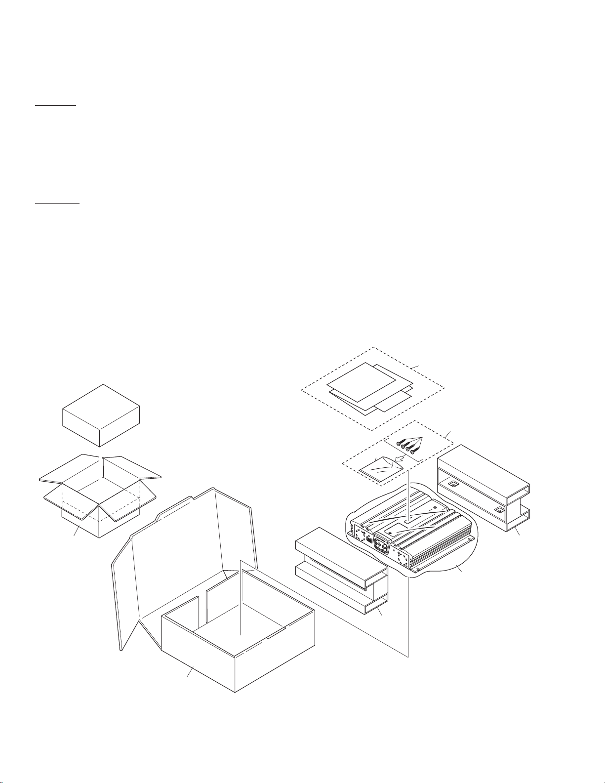
2.1 PACKING
3
4
2
10
8
9
6
7
9
Fig. 1
1 •••••
* 2 Screw Assy HEA0017
3 Screw BYC40P180FZK
4 Polyethylene Bag HEG0011
5 •••••
6 Polyethylene Bag HEG0013
7 Carton
See Contrast table (2)
8 Contain Box See Contrast table (2)
9 Protector HHP0025
10-1 Owner's Manual
See Contrast table (2)
10-2 Owner's Manual See Contrast table (2)
* 10-3 Warranty Card See Contrast table (2)
* 10-4 Warranty Card See Contrast table (2)
* 10-5 Card See Contrast table (2)
(1) PACKING SECTION PARTS LIST
Mark No. Description Part No. Mark No. Description Part No.
3
GM-X622,GM-X522
NOTE:
- Parts marked by “*”are generally unavailable because they are not in our Master Spare Parts List.
- Screws adjacent to Ñ mark on the product are used for disassembly.
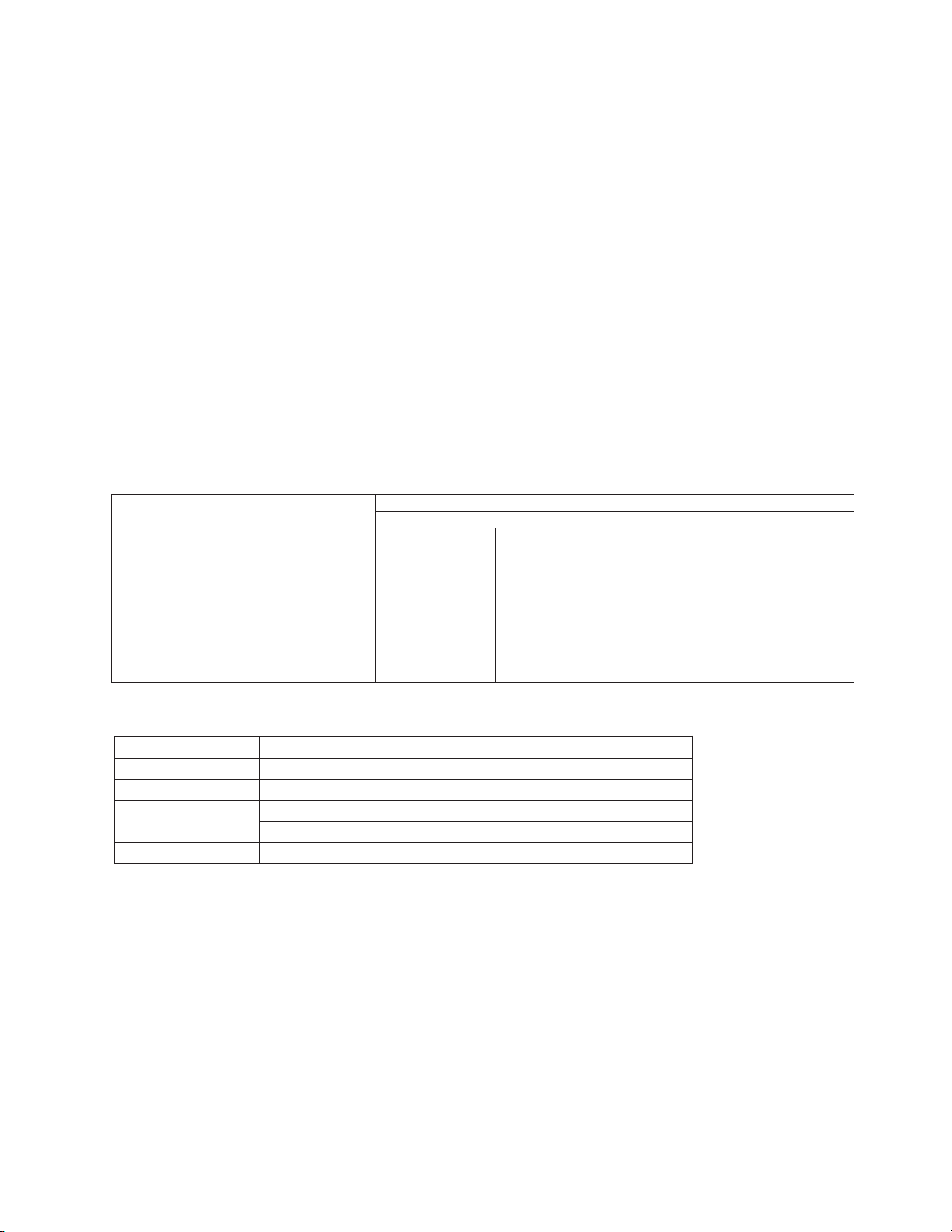
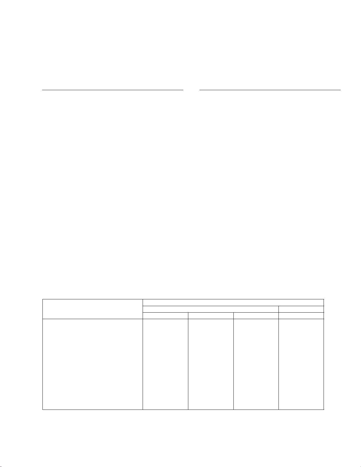
(2) CONTRAST TABLE
GM-X622/X1R/EW, GM-X622/X1R/UC, GM-X622/X1R/ES and GM-X522/X1R/UC are constructed the same except for the
following:
Part No.
GM-X622 GM-X522
Mark No. Symbol and Description X1R/EW X1R/UC X1R/ES X1R/UC
7 Carton HHG0153 HHG0149 HHG0152 HHG0150
8 Contain Box HHL0153 HHL0149 HHL0152 HHL0150
10-1 Owner’s Manual HRD0044 HRD0041 HRD0043 HRD0042
10-2 Owner’s Manual Not used Not used HRD0070 Not used
* 10-3 Warranty Card Not used HRY0005 Not used HRY0005
* 10-4 Warranty Card HRY1087 HRY1070 Not used Not used
* 10-5 Card Not used Not used Not used ARY1048
- Owner's Manual
Model Part No. Language
GM-X622/X1R/EW HRD0044 English, French, German, Dutch, Spanish, Italian
GM-X622/X1R/UC HRD0041 English, French
GM-X622/X1R/ES HRD0043 English, Spanish
HRD0070 Arabic, Portuguese(B)
GM-X522/X1R/UC HRD0042 English, French
4
GM-X622,GM-X522
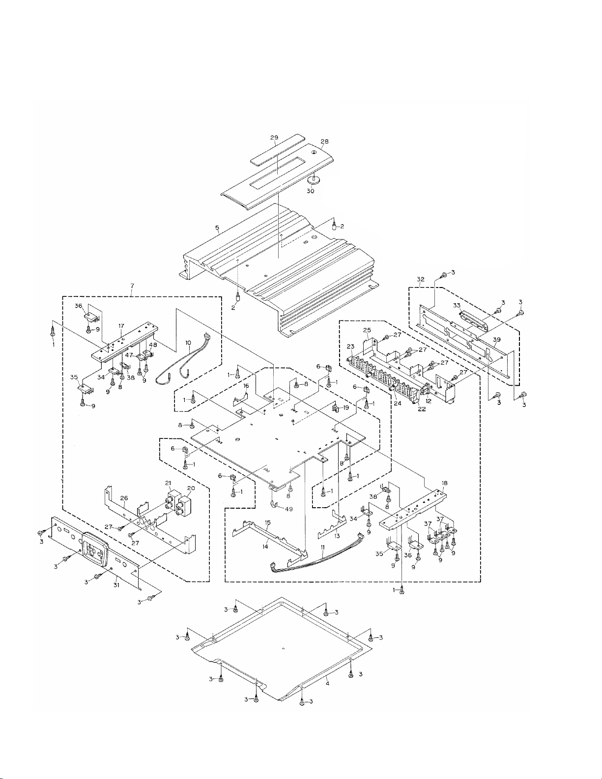
Fig. 2
2.2 EXTERIOR
5
GM-X622,GM-X522
1 Screw(M3´12) CBA1323
2 Screw(M3´5) HBA0006
3 Screw(M3´8) HBA0011
4 Case HNB0027
5 Heat Sink
See Contrast table (2)
6 Spacer HNV3975
7 Amp Unit
See Contrast table (2)
8 Screw BMS30P060FZK
9 Screw BMS30P080FMC
10 Cord Assy HDE0019
11 Connector HDE0013
12 Fuse(25A) HEK0025
13 Bass Bar HNC0039
14 Bass Bar HNC0040
15 Bass Bar HNC0041
16 Bass Bar HNC0043
17 Heat Sink HNR0088
18 Heat Sink HNR0089
19 Clamper HNV0015
20 Pin Jack(CN851)
See Contrast table (2)
21 Pin Jack(CN855)
See Contrast table (2)
22 Terminal(CN901)
See Contrast table (2)
23 Terminal(CN651)
See Contrast table (2)
24 Terminal(CN852)
See Contrast table (2)
25 Holder HNC0025
26 Holder HNC0026
27 Screw PPZ30P060FZK
28 Plate Unit
See Contrast table (2)
29 Badge Unit
See Contrast table (2)
30 Light Pipe Unit HXA0201
31 Panel Unit
See Contrast table (2)
32 Panel Unit
See Contrast table (2)
33 Plate HNS0039
34 Transistor(Q565,566) 2SC1568
35 Transistor(Q567,568) 2SD2438
36 Transistor(Q569,570) 2SB1587
37 FET(Q905,906,911,912) IRFIZ44N
38 Thermistor(TH901,902) CCX1013
* 39 Panel HNB0035
40–46 •••••
47 Diode(D907) YG902C2
48 Diode(D910) YG902N2
49 Clip
See Contrast table (2)
(1) EXTERIOR SECTION PARTS LIST
Mark No. Description Part No. Mark No. Description Part No.
NOTE:
- Parts marked by “*”are generally unavailable because they are not in our Master Spare Parts List.
- Screws adjacent to Ñ mark on the product are used for disassembly.
(2) CONTRAST TABLE
GM-X622/X1R/EW, GM-X622/X1R/UC, GM-X622/X1R/ES and GM-X522/X1R/UC are constructed the same except for the
following:
Part No.
GM-X622 GM-X522
Mark No. Symbol and Description X1R/EW X1R/UC X1R/ES X1R/UC
5 Heat Sink HNR0104 HNR0071 HNR0104 HNR0103
7 Amp Unit HWH0042 HWH0040 HWH0044 HWH0043
20 Pin Jack(CN851) HKB0001 HKB0002 HKB0001 HKB0001
21 Pin Jack(CN855) HKB0001 HKB0002 HKB0001 HKB0001
22 Terminal(CN901) HKE0001 HKE0002 HKE0001 HKE0001
23 Terminal(CN651) HKE0009 HKE0010 HKE0009 HKE0009
24 Terminal(CN852) HKE0013 HKE0015 HKE0013 HKE0013
28 Plate Unit HXA0108 HXA0107 HXA0108 HXA0108
29 Badge Unit HXA0113 HXA0261 HXA0113 HXA0113
31 Panel Unit HXA0256 HXA0254 HXA0256 HXA0245
32 Panel Unit HXA0259 HXA0260 HXA0259 HXA0259
49 Clip Not used HNC0054 Not used Not used
6
GM-X622,GM-X522
A
1
234
B
C
D
12
34
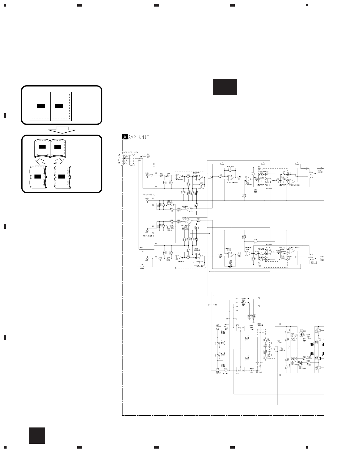
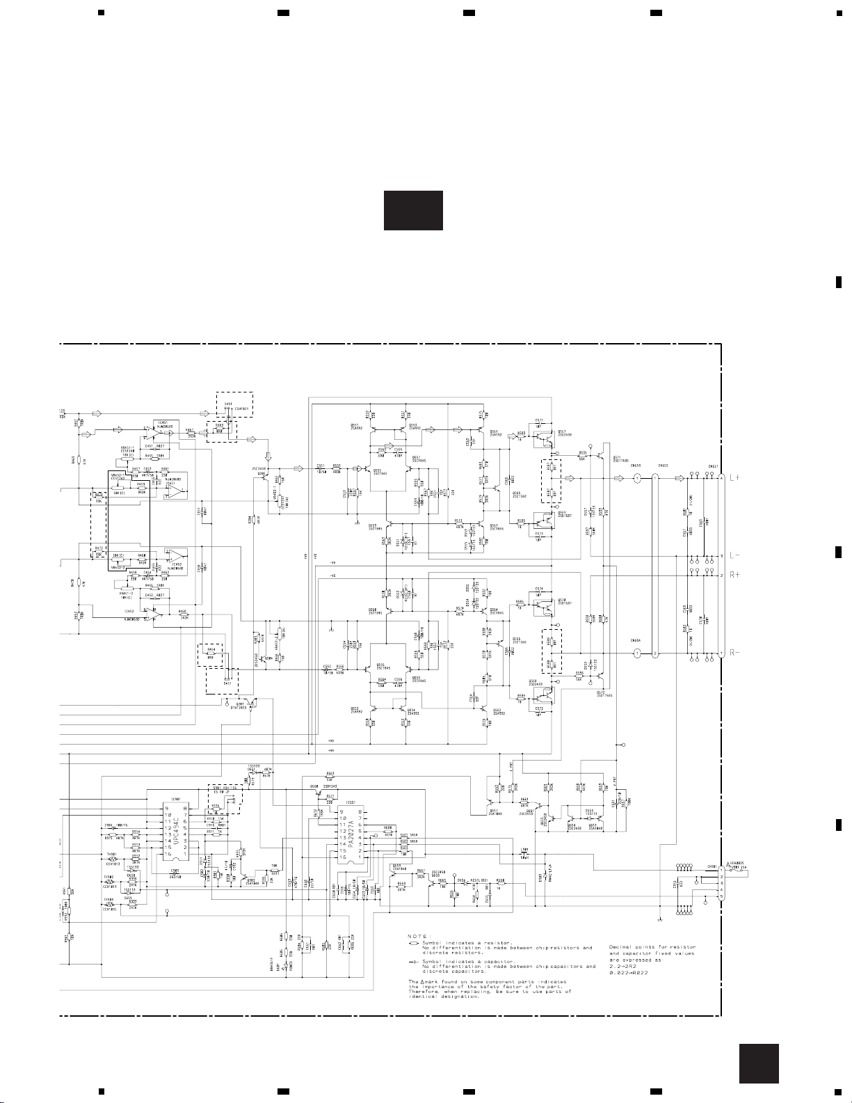
3. SCHEMATIC DIAGRAM
3.1 OVERALL CONNECTION DIAGRAM(GUIDE PAGE)
Note: When ordering service parts, be sure to refer to “EXPLODED VIEWS AND PARTS LIST” or “ELECTRICAL PARTS
LIST”.
A-a A-b
A-aA-a
A-b A-b
A-b A-b
A-a A-a
Large size
SCH diagram
Guide page
Detailed page
A
A-a
SPEAKER
INPUT
Lch
INPUT
Rch
INPUT
3
4
2
1
20K(E)
20K(E)
20K(E)
20K(E)
7
9
8
6
3
4
2
1
5
7
6
8
DC-AC INVERTER
REGULATOR
RECTIFICATION
VR101:FREQUENCY
S101:LPF/HPF
ISOLATOR
LPF
HPF
7
GM-X622,GM-X522
5
6
7
8
A
B
C
D
5
6
7
8
Fig. 3
A-b
A
POWER AMP
BFC
THERMO DETECTOR / PROTECTOR
OVER VOLTAGE DETECTOR / PROTECTOR
MUTE CONTROL
REGULATOR CONTROL
VR451:BASS BOOST LEVEL
VR452:BASS BOOST fc
VR453:GAIN
S451:BASS BOOST
BASS BOOST
SWITCHING
CONTROL
 Loading...