


FX-M2137ZSA
Pioneer FX-M2137ZSA, FX-M2137UC, FX-M2037ZSA, FX-M2137X1B, FX-M2037X1B Service Manual
...
PIONEER CORPORATION 4-1, Meguro 1-Chome, Meguro-ku, Tokyo 153-8654, Japan
PIONEER ELECTRONICS (USA) INC. P.O.Box 1760, Long Beach, CA 90801-1760 U.S.A.
PIONEER EUROPE NV Haven 1087 Keetberglaan 1, 9120 Melsele, Belgium
PIONEER ELECTRONICS ASIACENTRE PTE.LTD. 253 Alexandra Road, #04-01, Singapore 159936
C PIONEER CORPORATION 2003
K-ZZA. APR. 2003 Printed in Japan
ORDER NO.
CRT3086
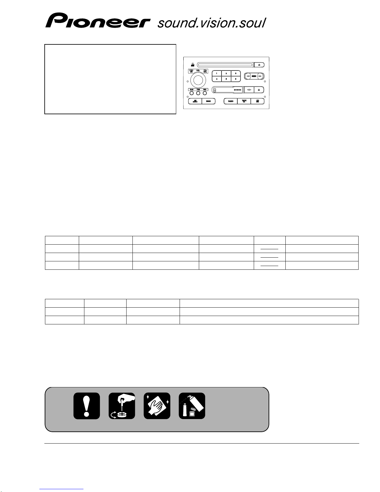
HEAD UNIT(3 in 1)
FX-M2137ZSA X1B/UC
FX-M2037
ZSA X1B/EW
FX-M2337ZSA X1B/ES
SAAB
FX-M2137ZSA/X1B/UC
VEHICLE DESTINATION PRODUCED AFTER PART No. ID No. PIONEER MODEL No.
SAAB 9-5 U.S.A., CANADA September 2003 5374640 FX-M2137ZSA/X1B/UC
SAAB 9-5 EUROPE September 2003 5374632 FX-M2037ZSA/X1B/EW
SAAB 9-5 GENERAL AREA September 2003 5374665 FX-M2337ZSA/X1B/ES
- This service manual should be used together with the following manual(s):
Model No. Order No. Mech. Module Remarks
CX-1011 CRT2406 3L Cassette Mech. Module : Mech. Description, Disassembly
CX-3026 CRT2944 S10 CD Mech. Module : Circuit Description, Mech. Description, Disassembly
- Dolby noise reduction manufactured under license from Dolby Laboratories Licensing Corporation.
"Dolby" and the double-D symbol are trademarks of Dolby Laboratories Licensing Corporation.
For details, refer to "Important symbols for good services".
2
1
234
12
34
F
E
D
C
B
A
FX-M2137ZSA/X1B/UC
- CD Player Service Precautions
1. Before disassembling the unit, be sure to turn off the
power. Unplugging and plugging the connectors dur-
ing power-on mode may damage the ICs inside the
unit.
2. To protect the pickup unit from electrostatic dis-
charge during serviving, take an appropriate treat-
ment(shorting-solder) by referring to "the DISAS-
SEMBLY" on page 79.
3. After replacing the pickup unit, be sure to check the
grating.(See p.76.)
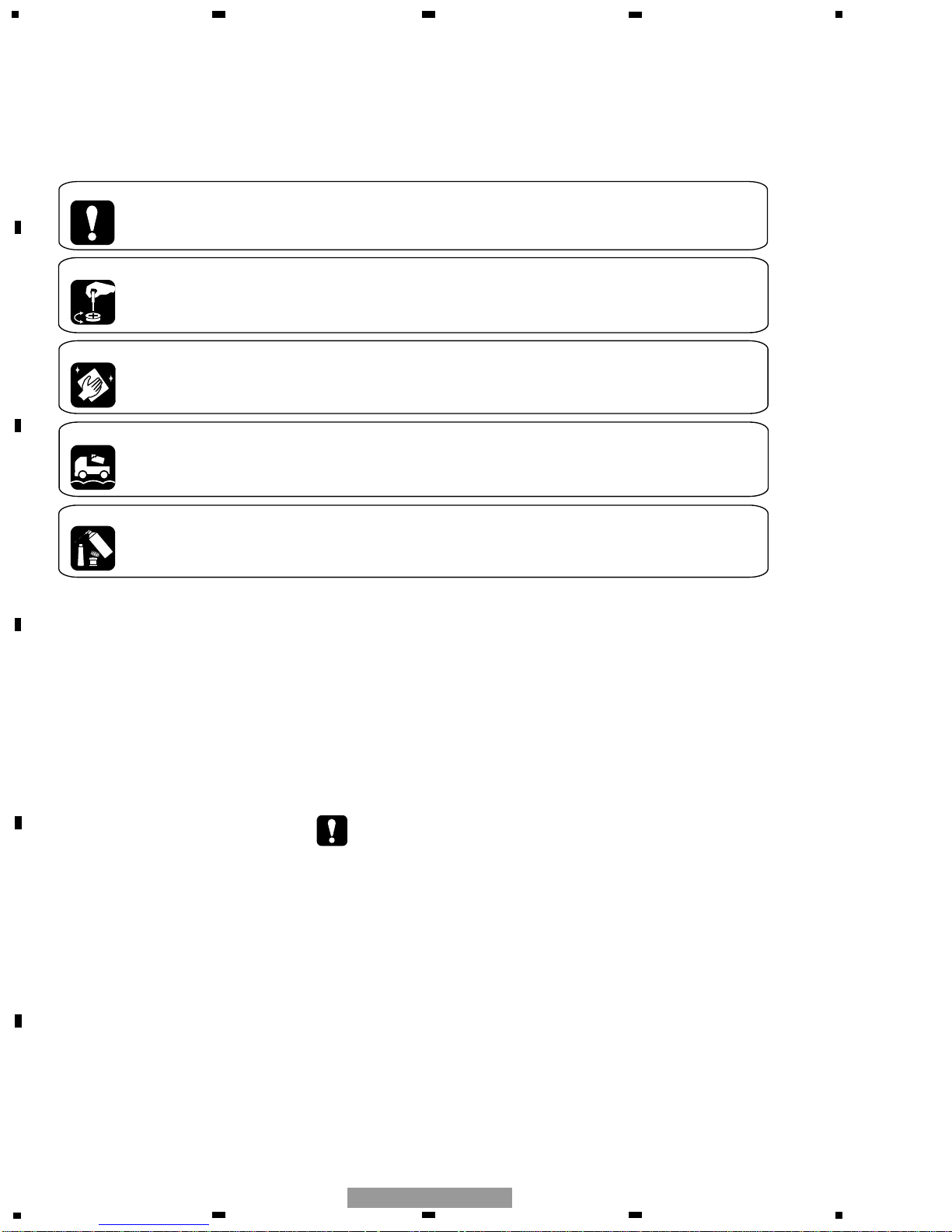
[ Important symbols for good services ]
In this manual, the symbols shown-below indicate that adjustments, settings or cleaning should be made securely.
When you find the procedures bearing any of the symbols, be sure to fulfill them:
1. Product safety
You should conform to the regulations governing the product (safety, radio and noise, and other regulations), and
should keep the safety during servicing by following the safety instructions described in this manual.
2. Adjustments
To keep the original performances of the product, optimum adjustments or specification confirmation is indispensable.
In accordance with the procedures or instructions described in this manual, adjustments should be performed.
3. Cleaning
For optical pickups, tape-deck heads, lenses and mirrors used in projection monitors, and other parts requiring cleaning,
proper cleaning should be performed to restore their performances.
4. Shipping mode and shipping screws
To protect the product from damages or failures that may be caused during transit, the shipping mode should be set or
the shipping screws should be installed before shipping out in accordance with this manual, if necessary.
5. Lubricants, glues, and replacement parts
Appropriately applying grease or glue can maintain the product performances. But improper lubrication or applying
glue may lead to failures or troubles in the product. By following the instructions in this manual, be sure to apply the
prescribed grease or glue to proper portions by the appropriate amount.For replacement parts or tools, the prescribed
ones should be used.
3
This service manual is intended for qualified service technicians; it is not meant for the casual do-it-yourselfer.
Qualified technicians have the necessary test equipment and tools, and have been trained to properly and safely
repair complex products such as those covered by this manual.
Improperly performed repairs can adversely affect the safety and reliability of the product and may void the warranty.
If you are not qualified to perform the repair of this product properly and safely, you should not risk trying to do so
and refer the repair to a qualified service technician.
1. Safety Precautions for those who Service this Unit.
• When checking or adjusting the emitting power of the laser diode exercise caution in order to get safe, reliable
results.
Caution:
1. During repair or tests, minimum distance of 13cm from the focus lens must be kept.
2. During repair or tests, do not view laser beam for 10 seconds or longer.
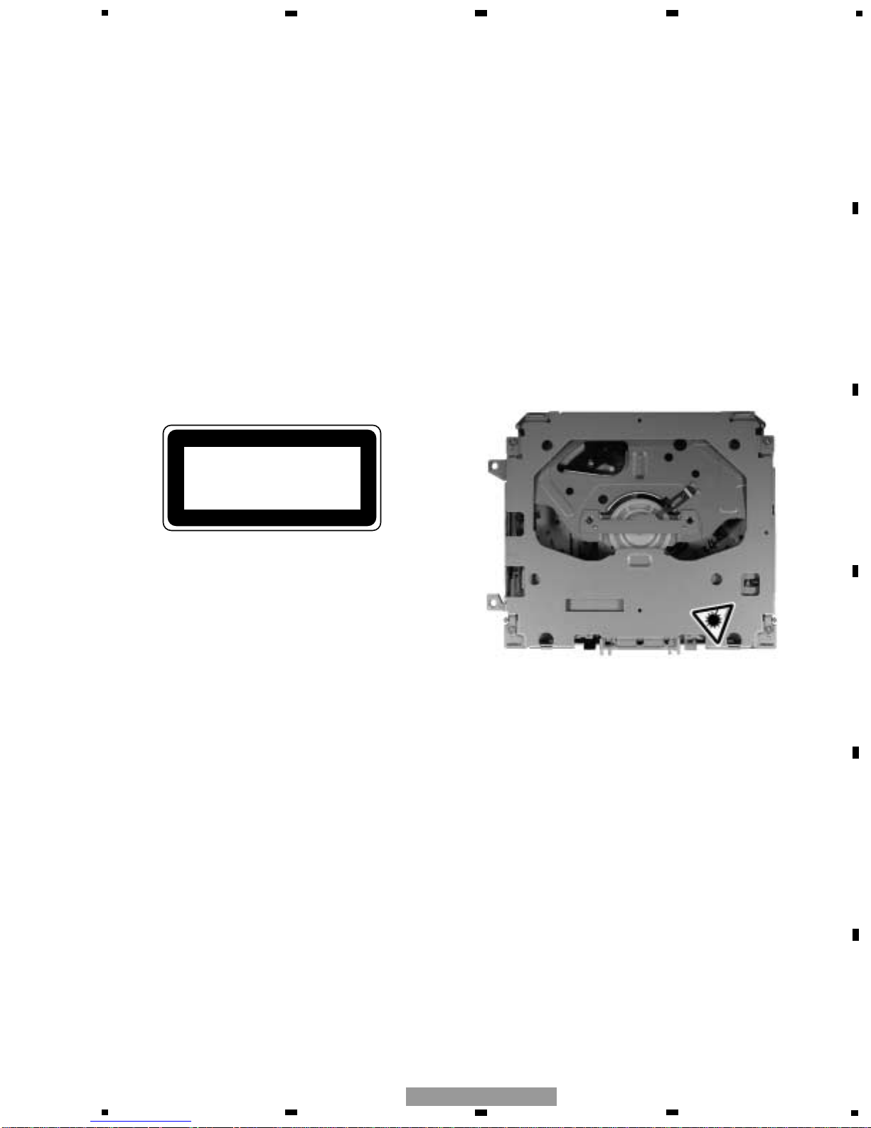
2. A “CLASS 1 LASER PRODUCT” label is affixed to the
bottom of the player.
3. The triangular label is attached to the mechanism
unit frame.
4. Specifications of Laser Diode
Specifications of laser radiation fields to which human access is possible during service.
Wavelength = 800 nanometers
CLASS 1
LASER PRODUCT
5
6
7
8
F
E
D
C
B
A
5
6
7
8
FX-M2137ZSA/X1B/UC
SAFETY INFORMATION
- FX-M2037ZSA/X1B/EW

4
1
234
12
34
F
E
D
C
B
A
FX-M2137ZSA/X1B/UC
CONTENTS
SAFETY INFORMATION ............................................................................................................................................3
1. SPECIFICATIONS .......................................................................................................................................................5
2. EXPLODED VIEWS AND PARTS LIST.......................................................................................................................7
2.1 PACKING...............................................................................................................................................................7
2.2 EXTERIOR.............................................................................................................................................................8
2.3 CD MECHANISM MODULE ...............................................................................................................................12
2.4 CASSETTE MECHANISM MODULE .................................................................................................................14
3. BLOCK DIAGRAM AND SCHEMATIC DIAGRAM...................................................................................................16
3.1 BLOCK DIAGRAM(FX-M2137ZSA/X1B/UC, FX-M2337ZSA/X1B/ES) .............................................................16
3.2 BLOCK DIAGRAM(FX-M2037ZSA/X1B/EW).....................................................................................................18
3.3 OVERALL CONNECTION DIAGRAM(GUIDE PAGE) ........................................................................................20
3.4 TUNER UNIT(FX-M2137ZSA/X1B/UC, FX-M2337ZSA/X1B/ES) .....................................................................26
3.5 TUNER UNIT(FX-M2037ZSA/X1B/EW).............................................................................................................28
3.6 CD MECHANISM MODULE ...............................................................................................................................30
3.7 CASSETTE MECHANISM MODULE .................................................................................................................34
3.8 SUB TUNER UNIT(FX-M2037ZSA/X1B/EW) ....................................................................................................36
4. PCB CONNECTION DIAGRAM ................................................................................................................................38
4.1 TUNER MOTHER PCB........................................................................................................................................38
4.2 CONNECTOR PCB..............................................................................................................................................42
4.3 SUB TUNER UNIT(FX-M2037ZSA/X1B/EW) ....................................................................................................43
4.4 TUNER UNIT ......................................................................................................................................................44
4.5 KEYBOARD UNIT ...............................................................................................................................................46
4.6 VOLUME PCB(A) ................................................................................................................................................48
4.7 VOLUME PCB(B) ................................................................................................................................................49
4.8 CD MECHANISM MODULE ...............................................................................................................................50
4.9 CASSETTE MECHANISM MODULE .................................................................................................................52
5. ELECTRICAL PARTS LIST........................................................................................................................................54
6. ADJUSTMENT .........................................................................................................................................................70
6.1 JIG CONNECTION DIAGRAM ...........................................................................................................................70
6.2 TUNER, CASSETTE ADJUSTMENT .................................................................................................................71
6.3 CD ADJUSTMENT .............................................................................................................................................74
6.4 CHECKING THE GRATING AFTER CHANGING THE PICKUP UNIT................................................................76
6.5 ERROR MODE ....................................................................................................................................................78
7. GENERAL INFORMATION .......................................................................................................................................79
7.1 DIAGNOSIS ........................................................................................................................................................79
7.1.1 DISASSEMBLY ..............................................................................................................................................79
7.1.2 PCB LOCATIONS...........................................................................................................................................84
7.1.3 CONNECTOR FUNCTION DESCRIPTION ....................................................................................................85
7.2 IC .........................................................................................................................................................................86
7.3 EXPLANATION...................................................................................................................................................94
7.3.1 SYSTEM BLOCK DIAGRAM .........................................................................................................................94
7.3.2 OPERATIONAL FLOW CHART......................................................................................................................95
7.4 CLEANING ..........................................................................................................................................................96
8. OPERATIONS ...........................................................................................................................................................97

5
5
6
7
8
F
E
D
C
B
A
5
6
7
8
FX-M2137ZSA/X1B/UC
1. SPECIFICATIONS
- FX-M2137ZSA/X1B/UC
Power source.....................................................13.5V±0.1V
Grounding system........................................Negative type
Dimensions ....................195.6(W)
x118.2(H)x183.5(D)mm
Weight ........................................................................2230g
Backup current ..............................................0.3mA or less
AUDIO
Tone control
Tone charact bass........................................................±9dB
Tone charact treble......................................................±9dB
Fader charact..................................................-30dB or less
Balance charact ..............................................-30dB or less
CD
System ...................................Compact disc audio system
Usable discs ..................................................Compact disc
Signal ...................................Sampling frequency:44.1kHz
Number of quantization bits:16;linear
S/N .................................................................80dB or more
Distortion........................................................0.03% or less
Separation .....................................................70dB or more
TAPE
Tape................................Compact cassette tape(C30-C90)
Tape speed ......4.76 cm/sec.(+0.14 cm/sec.,-0.05 cm/sec.)
Crosstalk ..........................................................40dB or less
Separation .....................................................35dB or more
S/N .................................................................45dB or more
Distortion.............................................................2% or less
FM TUNER
Frequency ...................................................78.9-107.9 MHz
Usable sensitivity .........................................................9dBf
S/N .................................................................50dB or more
Distortion..........................................................1.0% or less
Separation .....................................................25dB or more
AM TUNER
Frequency.......................................................530-1710 kHz
Selectivity .........................................45dB or more(±9kHz)
S/N .................................................................45dB or more
Distortion..........................................................1.0% or less
- FX-M2037ZSA/X1B/EW
Power source.....................................................13.5V±0.1V
Grounding system........................................Negative type
Dimensions ....................195.6(W)
x118.2(H)x183.5(D)mm
Weight ........................................................................2295g
Backup current ..............................................0.3mA or less
AUDIO
Tone control
Tone charact bass........................................................±9dB
Tone charact treble......................................................±9dB
Fader charact..................................................-30dB or less
Balance charact ..............................................-30dB or less
CD
System ...................................Compact disc audio system
Usable discs ..................................................Compact disc
Signal ...................................Sampling frequency:44.1kHz
Number of quantization bits:16;linear
S/N .................................................................80dB or more
Distortion........................................................0.03% or less
Separation .....................................................70dB or more
TAPE
Tape................................Compact cassette tape(C30-C90)
Tape speed ......4.76 cm/sec.(+0.14 cm/sec.,-0.05 cm/sec.)
Crosstalk ..........................................................40dB or less
Separation .....................................................35dB or more
S/N .................................................................45dB or more
Distortion.............................................................2% or less
FM TUNER
Frequency ...................................................87.5-108.0 MHz
Usable sensitivity .......................................................11dBf
S/N .................................................................50dB or more
Distortion..........................................................1.0% or less
Separation .....................................................25dB or more
MW/LW TUNER
Frequency .................................................153-281 kHz(LW)
........................................................531-1602kHz
Selectivity .........................................45dB or more(±9kHz)
S/N .................................................................40dB or more
Distortion..........................................................1.0% or less

6
1
234
12
34
F
E
D
C
B
A
FX-M2137ZSA/X1B/UC
- FX-M2337ZSA/X1B/ES
Power source.....................................................13.5V±0.1V
Grounding system........................................Negative type
Dimensions.....................195.6(W)x118.2(H)x183.5(D)mm
Weight ........................................................................2230g
Backup current ..............................................0.3mA or less
AUDIO
Tone control
Tone charact bass........................................................±9dB
Tone charact treble......................................................±9dB
Fader charact..................................................-30dB or less
Balance charact ..............................................-30dB or less
CD
System ...................................Compact disc audio system
Usable discs ..................................................Compact disc
Signal ...................................Sampling frequency:44.1kHz
Number of quantization bits:16;linear
S/N .................................................................80dB or more
Distortion........................................................0.03% or less
Separation .....................................................70dB or more
TAPE
Tape................................Compact cassette tape(C30-C90)
Tape speed ......4.76 cm/sec.(+0.14 cm/sec.,-0.05 cm/sec.)
Crosstalk ..........................................................40dB or less
Separation .....................................................35dB or more
S/N .................................................................45dB or more
Distortion.............................................................2% or less
FM TUNER
Frequency ...................................................87.5-108.0 MHz
Usable sensitivity .........................................................9dBf
S/N .................................................................50dB or more
Distortion..........................................................1.0% or less
Separation .....................................................25dB or more
AM TUNER
Frequency ............................................531-1602 kHz(9kHz)
530-1710 kHz(10kHz)
Selectivity .........................................45dB or more(±9kHz)
S/N .................................................................45dB or more
Distortion..........................................................1.0% or less

7
5
6
7
8
F
E
D
C
B
A
5
6
7
8
FX-M2137ZSA/X1B/UC
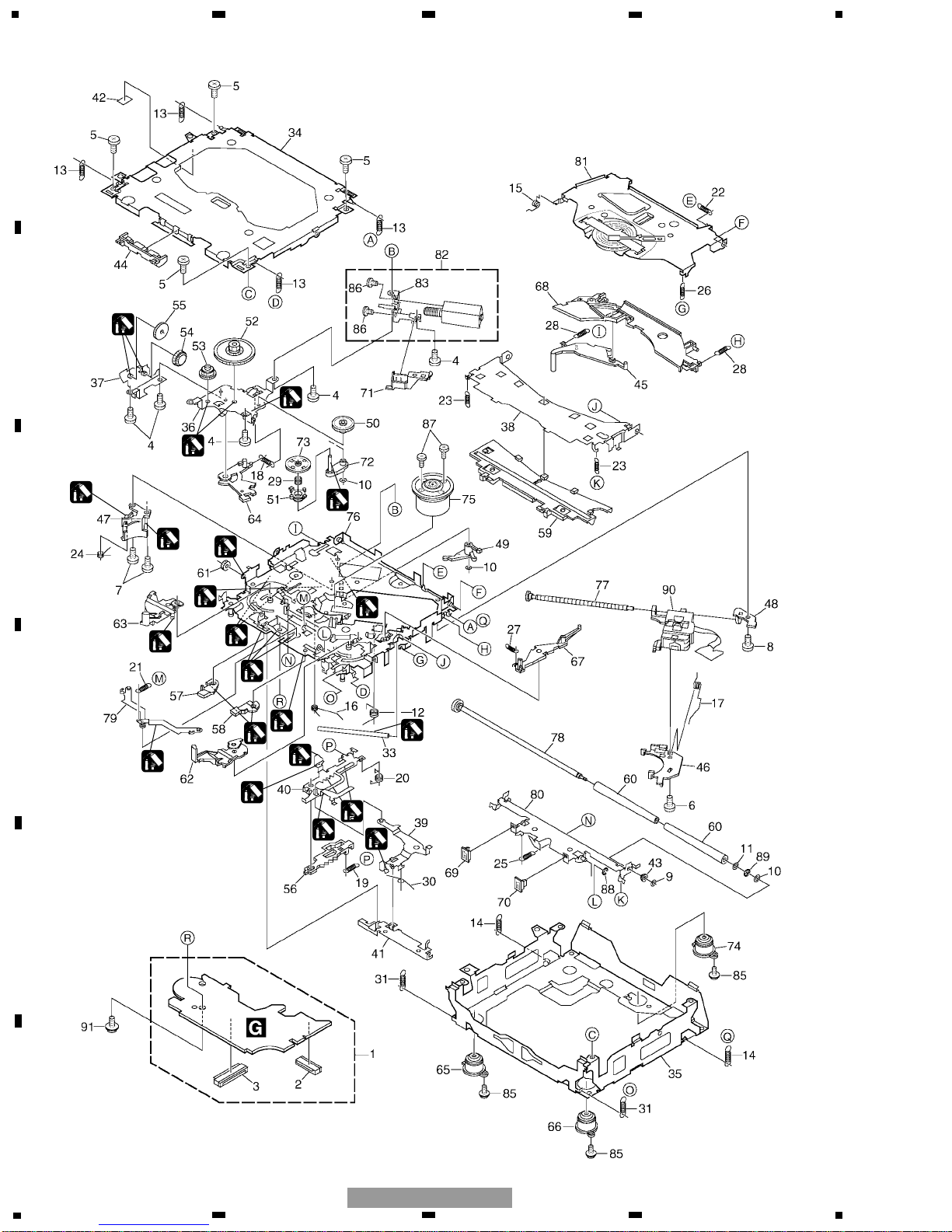
1 Cover UHW1584
2 Protector UHP1912
3 Polyethylene Bag UEG1057
4 Protector UHP1823
5 Protector UHP1825
6 Protector UHP1826
7 Protector UHP1824
8 Contain Box(UC) UHL-157
Contain Box(EW) UHL-156
Contain Box(ES) UHL-159
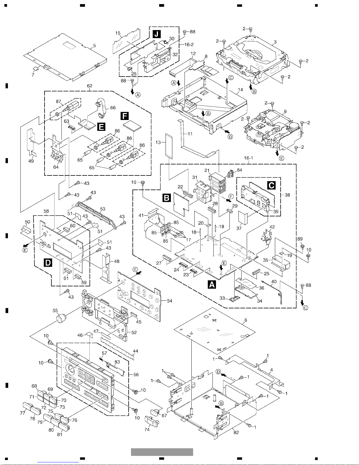
Mark No. Description Part No. Mark No. Description Part No.
- PACKING SECTION PARTS LIST
NOTE:
- Parts marked by “*” are generally unavailable because they are not in our Master Spare Parts List.
- Screws adjacent to ∇ mark on the product are used for disassembly.
- For the applying amount of lubricants or glue, follow the instructions in this manual.
(In the case of no amount instructions, apply as you think it appropriate.)
2
3
4
8
5
6
1
7
2. EXPLODED VIEWS AND PARTS LIST
2.1 PACKING
8
1
234
12
34
F
E
D
C
B
A
FX-M2137ZSA/X1B/UC
2.2 EXTERIOR

9
5
6
7
8
F
E
D
C
B
A
5
6
7
8
FX-M2137ZSA/X1B/UC
1 Screw BMZ30P050FTC
2 Screw BSZ26P050FTC
3
CD Mechanism Module(S10) CXK5626
4 Case CNB1958
5 Case CNB1959
* 6 Insulator CNM4418
7 Insulator CNM5247
8 Cover CNM5914
9
Cassette Mechanism ModuleEXK4220
10 Screw IMS30P050FTC
11 Connector
See Contrast table(2)
12 Flat Cable UDE-041
13 Connector UDE-042
14 Chassis UNA-006
15 Insulator
See Contrast table(2)
16 Tuner Mother Assy
See Contrast table(2)
17 Screw BMZ30P060FTC
18 Clamper
See Contrast table(2)
19 Terminal(CN803) CKF1059
20 Terminal(CN804) CKF1059
21 Connector(CN851) CKM1258
22 Connector(CN852) CKS1963
23 Plug(CN602) CKS3535
24 Plug(CN601) CKS3537
25 Connector(CN651) CKS3568
26 Connector(CN2)
See Contrast table(2)
27 Connector(CN701) CKS3703
28 Connector(CN801) CKS3866
29 Connector(CN552)
See Contrast table(2)
30 Mini Pin Jack(CN1)
See Contrast table(2)
31 Holder CNC5906
32 Holder
See Contrast table(2)
33 Shield
See Contrast table(2)
34 Shield
See Contrast table(2)
35 Shield
See Contrast table(2)
36 Insulator
See Contrast table(2)
* 37 Insulator CNM4912
38 Tuner Unit
See Contrast table(2)
39 Holder CNC6122
40 Antenna Cable(CN551)
See Contrast table(2)
41 Holder UNC-013
42 Antenna Unit(CN501) UXA-053
43 Screw BPZ26P100FTC
44 Cover CNM4768
45 Spacer CNM4949
46 Insulator CNM5247
47 Film CNM5299
48 Insulator CNM5452
49 Insulator CNM5453
50 Insulator CNM5454
51 Spacer CNM5455
52 Lighting Conductor CNV4220
53 Holder CNV4535
54 Rubber CNV5020
55 Knob Assy CXB5608
56 Grille Unit CXB9862
57 Spring CBH1371
58 Keyboard Unit UWM-021
59 Socket(CN902) CKS3548
60 Socket(CN903) CKS3548
61 Socket(CN901) CKS3550
62 Volume Unit UWM-032
63 Plug(CN905) CKS3535
64 Holder CNC6818
65 Knob Assy CXA7840
66 Connector(CN904) UDE-043
67 Button(CD EJECT) UAC5703
68 Button(1) UAC5704
69 Button(2) UAC5705
70 Button(3) UAC5706
71 Button(4) UAC5707
72 Button(5) UAC5708
73 Button(6) UAC5709
74 Button(SEEK) UAC5710
75 Button(<>) UAC5711
76 Button(TAPE EJECT) UAC5712
77 Button(AS) UAC5713
78 Button
See Contrast table(2)
79 Button
See Contrast table(2)
80 Button(TAPE) UAC5716
81 Button(CD) UAC5717
82 Chassis Unit UXB-018
* 83 Door CAT1684
84 Fuse(FU851)(5A) CEK1005
85
Transistor(Q802, 815, 818) 2SB1185
86 Volume(VR902, 903, 904) CCS1089
87 Volume(VR901) CSD1036
88 Screw
See Contrast table(2)
89 Screw
See Contrast table(2)
(1) EXTERIOR SECTION PARTS LIST
Mark No. Description Part No. Mark No. Description Part No.
10
1
234
12
34
F
E
D
C
B
A
FX-M2137ZSA/X1B/UC
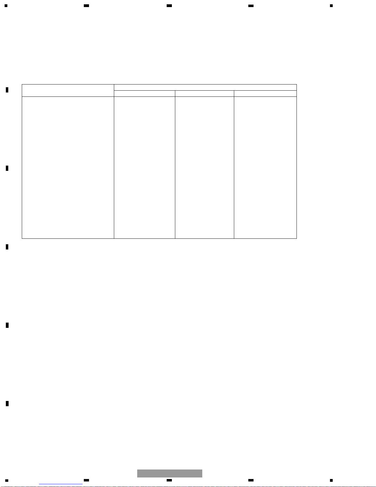
(2) CONTRAST TABLE
FX-M2137ZSA/X1B/UC, FX-M2037ZSA/X1B/EW and FX-M2337ZSA/X1B/ES are constructed the same
except for the following:
Part No.
Mark No. Symbol and Description FX-M2137ZSA/X1B/UC FX-M2037ZSA/X1B/EW FX-M2337ZSA/X1B/ES
11 Connector Not used UDE-040 Not used
15 Insulator Not used UNM-010 Not used
16 Tuner Mother Assy UWM-029 UWM-028 UWM-031
18 Clamper Not used CEF1034 Not used
26 Connector(CN2) Not used CKS3691 Not used
29 Connector(CN552) Not used CKS3904 Not used
30 Mini Pin Jack(CN1) Not used CKX1046 Not used
32 Holder Not used CNC6121 Not used
33 Shield Not used CNC6532 Not used
34 Shield Not used CNC6533 Not used
35 Shield Not used CNC7201 Not used
36 Insulator Not used CNM4808 Not used
38 Tuner Unit CWE1422 CWE1421 CWE1422
40 Antenna Cable(CN551) Not used UDH-006 Not used
78 Button UAC5720(BAND) UAC5714(TP) UAC5720(BAND)
79 Button UAC5721(RADIO) UAC5715(RADIO) UAC5721(RADIO)
88 Screw Not used BSZ26P050FTC Not used
89 Screw Not used IMS30P050FTC Not used

11
5
6
7
8
F
E
D
C
B
A
5
6
7
8
FX-M2137ZSA/X1B/UC
12
1
234
12
34
F
E
D
C
B
A
FX-M2137ZSA/X1B/UC
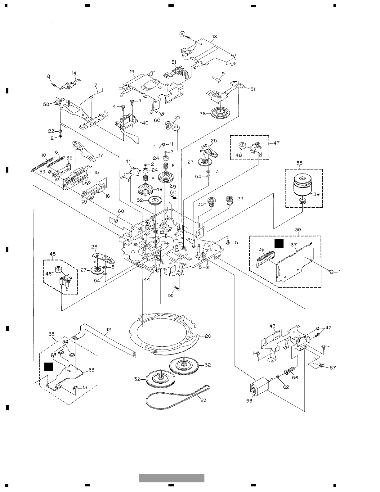
2.3 CD MECHANISM MODULE
1
1
1
2
1
2
1
2
2
2
1
1
1
1
2
1
3
1
1GEM1024
2GEM1045
3GEM1035
1
1
1

13
5
6
7
8
F
E
D
C
B
A
5
6
7
8
FX-M2137ZSA/X1B/UC
Mark No. Description Part No. Mark No. Description Part No.
1 CD Core Unit(S10) CWX2708
2 Connector(CN101) CKS4182
3 Connector(CN701) CKS4188
4 Screw BMZ20P035FTC
5 Screw BSZ20P040FTC
6 Screw(M2x4) CBA1362
7 Screw(M2x3) CBA1511
8 Screw(M2x3) CBA1527
9 Washer CBF1037
10 Washer CBF1038
11 Washer CBF1060
12 Spring CBH2390
13 Spring CBH2606
14 Spring CBH2607
15 Spring CBH2608
16 Spring CBH2609
17 Spring CBH2610
18 Spring CBH2611
19 Spring CBH2612
20 Spring CBH2613
21 Spring CBH2614
22 Spring CBH2615
23 Spring CBH2616
24 Spring CBH2617
25 Spring CBH2620
26 Spring CBH2621
27 Spring CBH2641
28 Spring CBH2642
29 Spring CBH2643
30 Spring CBH2659
31 Spring CBH2688
32 •••••
33 Shaft CLA3845
34 Frame CND1564
35 Frame CND1801
36 Bracket CNC9966
37 Bracket CNC9967
38 Arm CNC9968
39 Arm CNC9973
40 Lever CNC9983
41 Lever CNC9984
42 Sheet CNM8134
43 Collar CNV6906
44 Guide CNV6925
45 Arm CNV7198
46 Rack CNV7199
47 Holder CNV7201
48 Holder CNV7202
49 Arm CNV7203
50 Gear CNV7207
51 Gear CNV7208
52 Gear CNV7209
53 Gear CNV7210
54 Gear CNV7211
55 Gear CNV7212
56 Rack CNV7214
57 Arm CNV7215
58 Arm CNV7216
59 Guide CNV7217
60 Roller CNV7218
61 Gear CNV7219
62 Arm CNV7221
63 Arm CNV7220
64 Arm CNV7222
65 Damper CNV7634
66 Damper CNV7633
67 Arm CNV7341
68 Arm CNV7342
69 Guide CNV7360
70 Guide CNV7361
71 Holder CNV7437
72 Arm CNV7444
73 Gear CNV7595
74 Damper CNV7632
75 Motor Unit(M1) CXB6007
76 Chassis Unit CXB8728
77 Screw Unit CXB8729
78 Gear Unit CXB8731
79 Arm Unit CXB8732
80 Arm Unit CXB8735
81 Arm Unit CXB8852
82 Motor Unit(M2) CXB8933
83 Bracket CNC9985
84 •••••
85 Screw(M2x5) EBA1028
86 Screw JFZ20P020FTC
87 Screw JGZ17P022FTC
88 Washer YE15FTC
89 Washer YE20FTC
90 Pickup Unit(Service)(P10) CXX1641
91 Screw IMS26P030FTC
- CD MECHANISM MODULE SECTION PARTS LIST
14
1
234
12
34
F
E
D
C
B
A
FX-M2137ZSA/X1B/UC
2.4 CASSETTE MECHANISM MODULE
I
H

15
5
6
7
8
F
E
D
C
B
A
5
6
7
8
FX-M2137ZSA/X1B/UC
Mark No. Description Part No. Mark No. Description Part No.
1 Screw BSZ20P040FMC
2 Washer CBF1037
3 Washer CBG1003
4 Screw EBA1028
5 Screw CBA1037
6 Spring EBH1653
7 Spring EBH1642
8 Spring EBH1641
9 Spring EBH1626
10 Spring EBH1627
11 Spring EBH1648
12 Cord EDD1024
13 Photo-reflector(Q101) EGN1004
14 Arm ENC1526
15 Lever Unit EXA1610
16 Lever ENC1543
17 Arm ENC1532
18 Frame ENC1533
19 Holder ENC1547
20 Gear ENC1535
21 Arm ENC1550
22 Roller ENR1040
23 Belt ENT1027
24 Collar ENV1508
25 Arm ENV1539
26 Arm ENV1540
27 Gear ENV1569
28 Gear ENV1547
29 Gear ENR1044
30 Worm Wheel ENV1559
31 Lever ENV1551
32 Flywheel ENV1554
33 PCB ENP1196
34 Switch(S101,S102,S103) ESG1007
35 Deck Unit EWM1037
36 Plug(CN251) CKS3540
37 Gathering PCB ENX1069
38 Motor Unit(M1) EXA1491
39 Motor EXM1028
40 Head Assy(HD1) EXA1506
41 Arm ENC1537
42 Screw JGZ20P025FNI
43 Guide ENC1545
44 Chassis Unit EXA1609
45 Pinch Holder Unit EXA1608
46 Pinch Roller ENV1518
47 Pinch Holder Unit EXA1607
48 Pinch Roller ENV1518
49 Reel Unit EXA1585
50 Head Base Unit EXA1611
51 Lever Unit EXA1587
52 Gear Unit EXA1596
53 Motor Unit(M2) EXA1623
54 Washer HBF-179
55 Spring EBH1537
56 Worm Gear ENV1564
57 Spring EBH1654
58 Lever ENC1548
59 Washer YE15FUC
60 Tube ENM1039
61 Spring EBH1645
62 Spring EBH1647
63 Sensor Unit EWM1036
- CASSETTE MECHANISM MODULE SECTION PARTS LIST
16
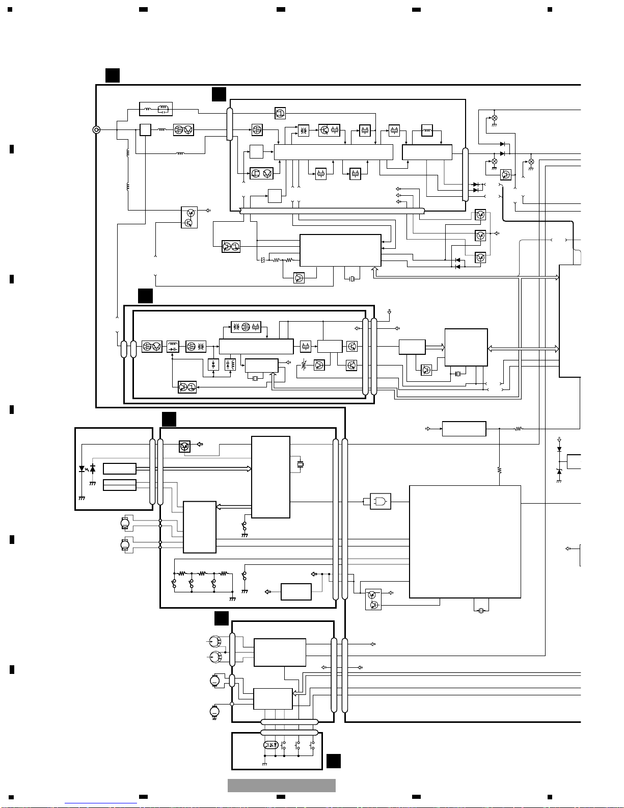
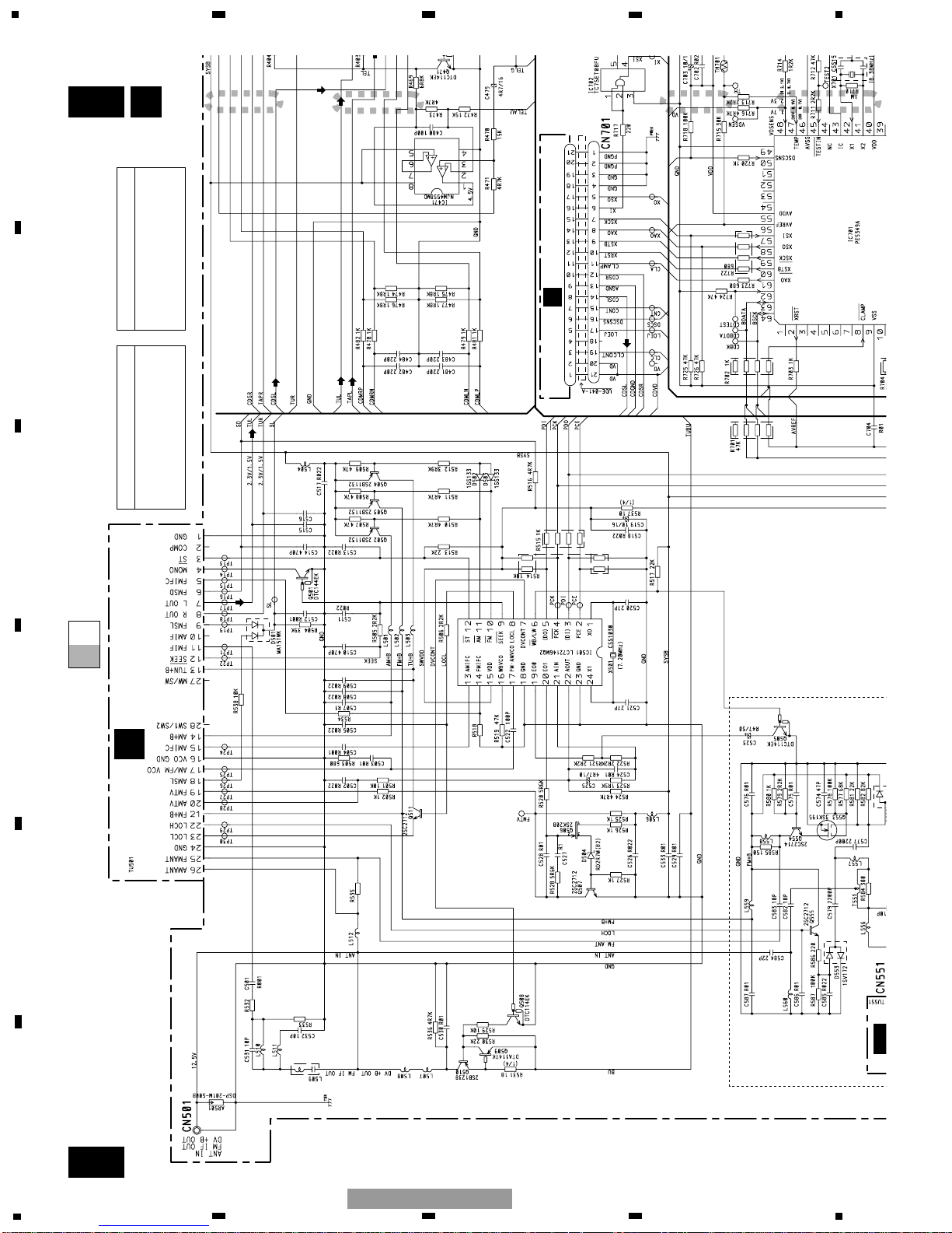
CN701
CN101
Q101
M
LASER
DIODE
MONITOR
DIODE
CLAMP
HOME
X201
12EJ
8EJ DSCSNS
FOCUS ACT.
SPINDLE
MOTOR
M
CARRIAGE
MOTOR
LOADING/
TRACKING ACT.
LD+
MD
FOP
TOP
14
5
4
1
PICKUP UNIT
(SERVICE)(P10)
HOLOGRAM
UNIT
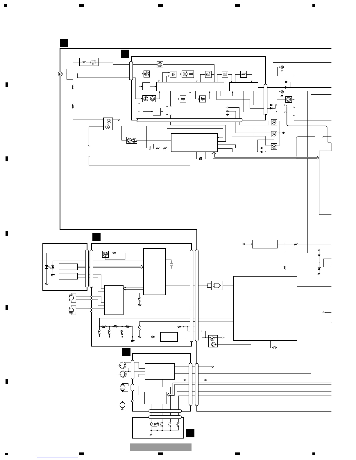
IC 301
BA5996FP
IC 201
UPD63712GC
IC 701
NJM2391DL1-33
3.3V REGULATOR
SERVO
CONTROL,
DSP,
LPF, DAC
ACT,MOTOR
DRIVER
1
VD
VD
3R3V
7
CONT
11
CLMP
5
LOEJ
6
DSCSNS
8
LOUT
TOP
FOP
16
SOP
15
SOM
17
LCOM
18
LCOP
22
1
LOEJ
23
20
LOUT
XTAL
xtal
24
9
CONT
12
FOP
FD, TD, SD, MD
AC, F, E, BD
1
LD
2
PD
42
LIMIT
3
13
TOP
2
16
SO
12
XSI
3R3V
ANTENNA
Q473
Q471
Q472
telon
SL
SD
SL
SD
47 76
Q503
Q502
Q504
SYSB
FM+B
AM+B
TUN+B
TUNER PLL
IC 501
LC72146MQ2
fm
am
11
10
17
13
FM-AM VCO
AM IFC
PDI/PCK/PDO/PCE
124
X501
Q507 Q506
EO0
AIN
EO1
19
21
20
22
AOUT
FM
LOOP FILTER
AM
LOOP FILTER
B.U
Q510
Q508
DIVERSTY
POWER SUPPLY
7
DV CONT
DV CONT
DV CONT
AM ANT
FM ANT
FM IF OUT
FM IF FILTER
7
19
9
18
6
43
FMSL
40
1
2
FM PROCESSOR
IC2 PA4024A
L52
4719
CF53
FM IF
CF52
171514
Q31 CF51
FM IF
T31
FM MIX
109
FM/AM PROCESSOR
IC1 PA4023B
41
Q3
FM RF
Q201
11
25
26
FM
OSC
AM
OSC
AMRF/AGC
AMTV
34
386
Q51
FMTV
AMIFC
VCO
32 36 16
18
31
30
28
23 25
CF232 AM IF
FM+B
AM+B
TUN+B
AMSL
FMSD
19 20 15
17
13 14 21
DVCONT
16
DSCSNS
LOEJ
XSI
VDSENS
clamp
8
50
11
57
48
DSCSNS
LOEJ
XI
clamp
Q815
Q816
CD POWER SUPPLY
B.U
VD
VDCON
33
4142
X701
X1
X2
CD CONTROLLER
IC 701
PE5349A
TAPE Lch
SYSB
TAPE+B
CN651
CN701
reset
60
VDD
2
1
SYSTEM
RESET
IC 801
S-80835CNUA-B8U
35
reset
PCE
PCE
2
VDD
BAC
SEN
IC
S-807
SYSB
POWE
ejsw
37
ej
load
stby
14
11
16
17
6
21
20
4
3
19
11
FM IF
CN501
B.U
20
CONT
15
CONT
13
CDS Lch
STBY
LOAD
5
1
4
2
1
IC251
CXA2560Q
IC351
PA2020A
EQ AMP
MECHANISM
DRIVER
CN251
CN252
CN254
CN255
CN253
7
5
TAPE+B
Lch
FWD
L-ch
REV
L-ch
37
36
39
17
3
15 6
8
7
10
CN256
3
15 6
S101
LOAD
S102
MODE
EGN1004
REEL
SENSE
M
M
M2
SUB
MOTOR
M1
MAIN
MOTOR
5
2
1
4
3
19
11
20
B.U
S103
70µs
18
4
4
CF230
TC7SET08FU
IC 702
2
4
1
Q101
A
TUNER MOTHER PCB
C
TUNER UNIT
G
CD CORE UNIT(S10)
H
DECK UNIT
I
SENSOR UNIT
1
234
12
34
F
E
D
C
B
A
FX-M2137ZSA/X1B/UC
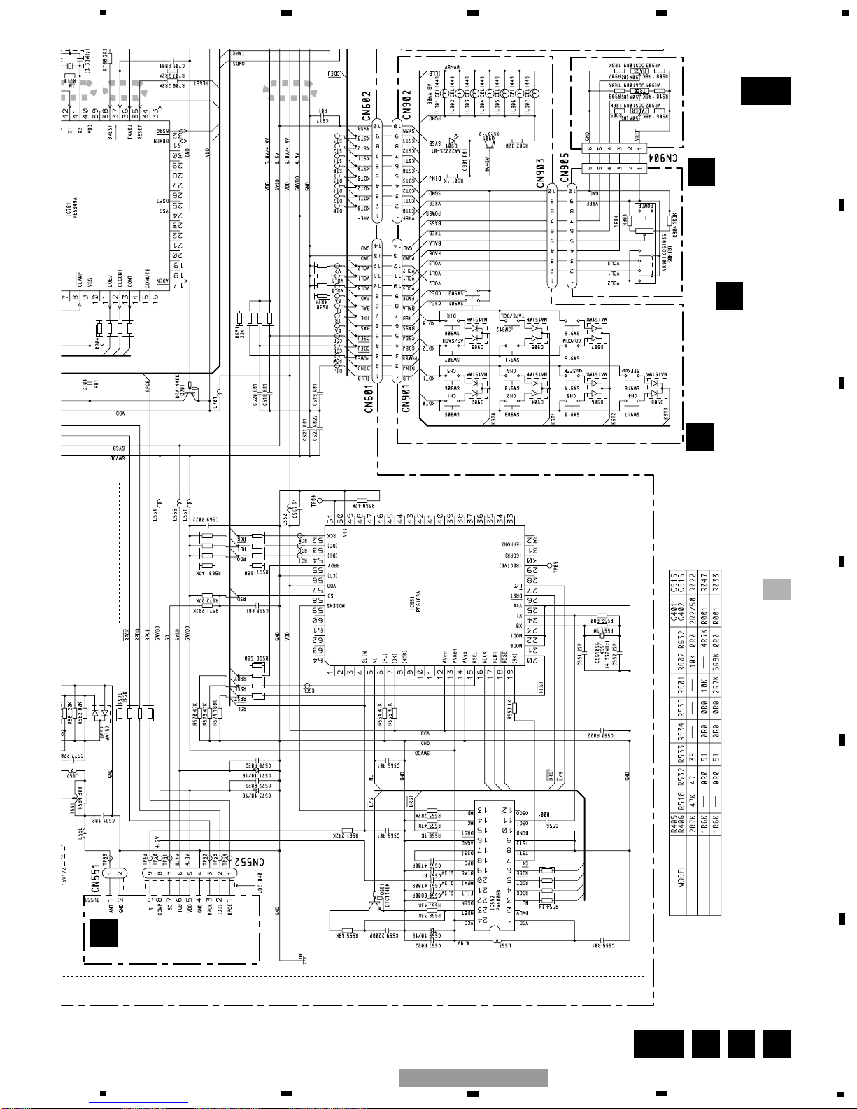
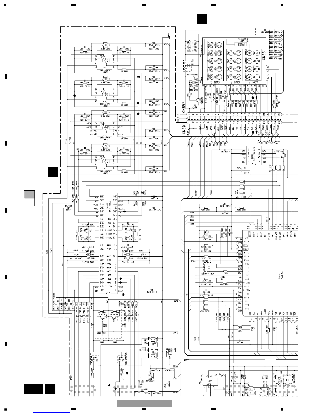
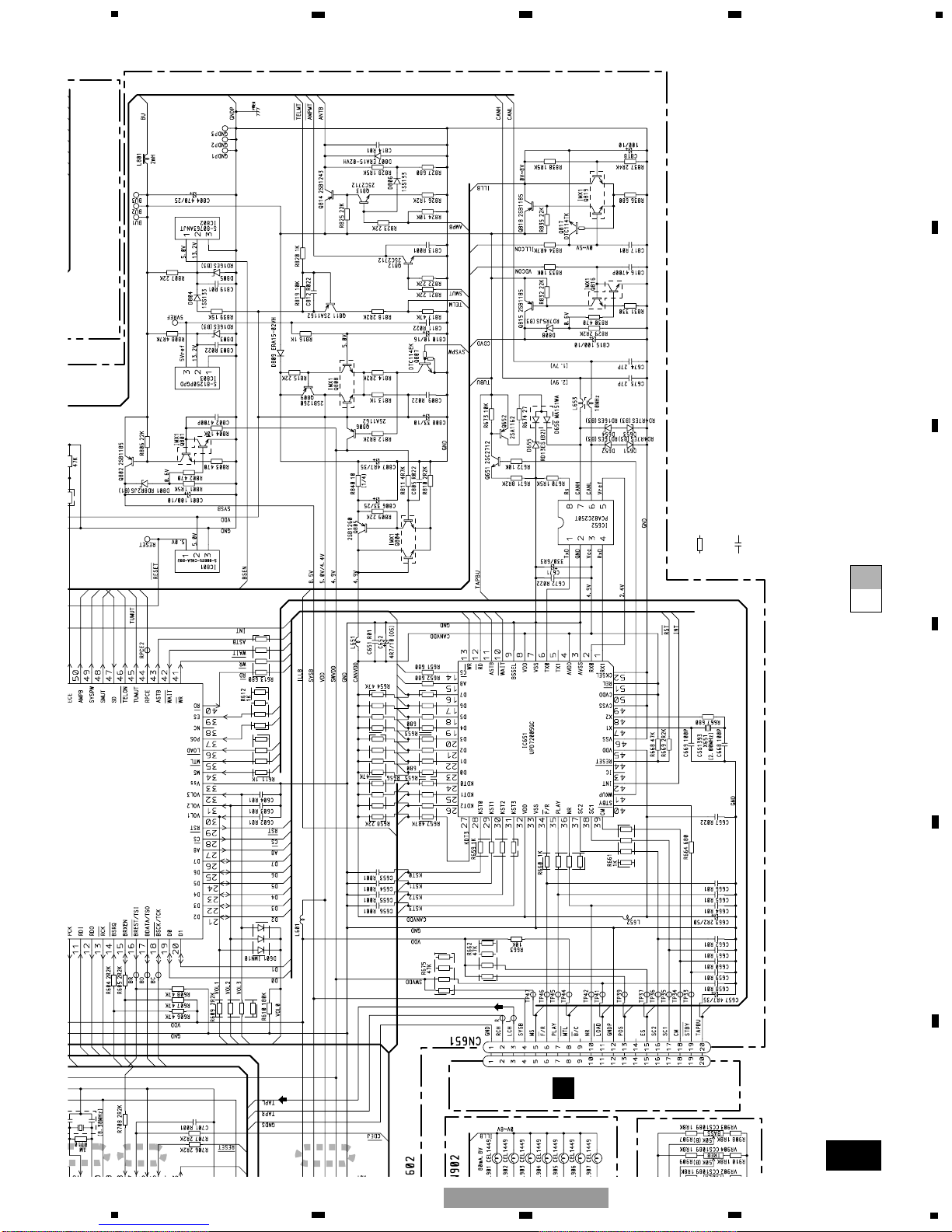
3. BLOCK DIAGRAM AND SCHEMATIC DIAGRAM
3.1 BLOCK DIAGRAM(FX-M2137ZSA/X1B/UC, FX-M2337ZSA/X1B/ES)

17
22 23 24 25 26
17 18 19 20 21
13 14 15 16
9101112
5678
1234
FU851
5A
CON A
CON B
CON C
Q851
23 25 26
17
18
12
16
11
13
5
6
27
8
EF851
CN852
1
2
3
6
9
11
10
19
18
17
16
8
7
20
21
25
13.2V
ANTB
IG(+5V)
TELMUTE
AMPMUTE
RL-
RL+
FL-
FL+
CANL
CANH
CDML-
CDML+
TELAU
1
2
3
6
9
11
10
19
18
17
16
8
7
20
21
25
B.U
B.U
Q814
Q813
ANTB
ANTENNA BOOSTER
IGSEN
Q811
telmt
TELM
Q812
ampmt
SMUT
RL-
RL+
FL-
FL+
CANL
CANH
CDM-
CDM+
L653
Q652
Q651
B.U
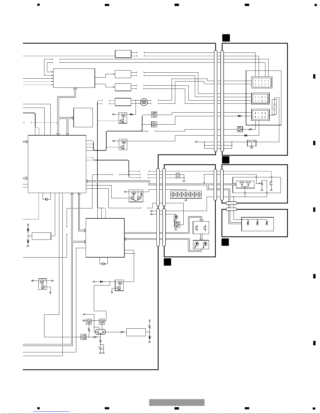
IC 652
PCA82C250T
CAN BUS DRIVER
7
6
IC 403
NJM4558MD
REAR AUDIO OUTPUT
1
7
IC 401
NJM4558MD
FRONT AUDIO OUTPUT
1
7
6
6
19
20
IC 405
SN761029DL
ELECTRONIC VOLUME CONTROL
WAKE UP DRIVER
AMPB
FL
RL
SYSTEM
CONTROLLER
IC 601
PE5378A
SMUT
TELM
igsen
AMPB
50
63
65
48
EEP ROM
IC 602
S-29220A
VST/VCK/VDT
EDI/EDO/
ECK/ECE
1
4
RXD
TXD
WKUP
TX0
RX1
WKUP
6141
CAN BUS
IC 651
UPD72005GC
CDM+
TU/TEL
CDS
TAPE
5
2
4
3
telon
46
SL
SD
47 76
reset
60
PCE
PCE
1
2
VDD
BACK UP
SENSOR
IC 802
S-80763ANJT
62
BSEN
4847
X651
X1
X2
B.U
Q802
Q801
SYSB
SWVDD
8.5V
POWER SUPPLY
power
csej
64
66
POWER
CSEJ
ejsw
ejsw
CDEJ
CDEJ
VOL1/VOL2/VOL3/BAL
FAD/TRE/BASS
DINJ
DINJ
6
ILLCON
ILLCON
B.U
SWVDD
SYSB
Q818
Q819
LAMP CONTROL
KDT0-KDT3
KST0-KST3
Q805
Q804
VDD
VDD
32
45
B.U
CAN VDD
POWER SUPPLY
CANVDD
SWVDD
SW
VDD
Q809Q806
VDD
49
SYSPW
load
36
SW5V
POWER
SUPPLY
Q807
Q808
stby
40
B.U
IC 803
S-81250PGPD
B.U 5V
REFERENCE
3
2
CN601
CN901
POWER
CDEJ
CSEJ
SW902
SW901
IL901-IL907
ILL+B
DINJ
D901
Q901
VERF
SYSB
KEY
LED
KDT0-KDT3
KST0-KST3
CN903
CN905
BALANCE
POWER
BALANCE
SW904 VOLUME
BALANCE
VR901
SW903
POWER
SWITCH
VREF
CN904
VR902
FADER
VR904
TREBLE
VR903
BASS
3
4
5
1
2
3
4
5
1
2
1
10
1
10
8
5
9
8
5
9
1
1
CN602
CN902
CN801
CDM-
6
5
IC 471
NJM4558MD
TEL AUDIO ISOLATOR
TELAU
TELG
22
TELG
1
2
3
24
24
6970
X601
X1
X2
FUSE
B
CONNECTOR PCB
E
VOLUME PCB(A)
F
VOLUME PCB(B)
D
KEYBOARD UNIT
5
6
7
8
F
E
D
C
B
A
5
6
7
8
FX-M2137ZSA/X1B/UC
18
CN701
CN101
Q101
M
LASER
DIODE
MONITOR
DIODE
CLAMP
HOME
X201
12EJ
8EJ DSCSNS
FOCUS ACT.
SPINDLE
MOTOR
M
CARRIAGE
MOTOR
LOADING/
TRACKING ACT.
LD+
MD
FOP
TOP
14
5
4
1
PICKUP UNIT
(SERVICE)(P10)
HOLOGRAM
UNIT
IC 301
BA5996FP
IC 201
UPD63712GC
IC 701
NJM2391DL1-33
3.3V REGULATOR
SERVO
CONTROL,
DSP,
LPF, DAC
ACT,MOTOR
DRIVER
1
VD
VD
3R3V
7
CONT
11
CLMP
5
LOEJ
6
DSCSNS
8
LOUT
TOP
FOP
16
SOP
15
SOM
17
LCOM
18
LCOP
22
1
LOEJ
23
20
LOUT
XTAL
xtal
24
9
CONT
12
FOP
FD, TD, SD, MD
AC, F, E, BD
1
LD
2
PD
42
LIMIT
3
13
TOP
2
16
SO
12
XSI
3R3V
Q473
Q471
Q472
telon
SL
SD
SL
SD
47 76
Q503
Q502
Q504
SYSB
FM+B
AM+B
TUN+B
TUNER PLL
IC 501
LC72146MQ2
fm
am
11
10
17
13
FM-AM VCO
AM IFC
PDI/PCK/PDO/PCE
124
X501
Q507 Q506
EO0
AIN
EO1
19
21
20
22
AOUT
FM
LOOP FILTER
AM
LOOP FILTER
B.U
Q510
Q508
DIVERSTY
POWER SUPPLY
7
DV CONT
DV CONT
DV CONT
AM ANT
FM ANT
FM IF OUT
FM IF FILTER
7
19
9
18
6
43
FMSL
40
1
2
FM PROCESSOR
IC2 PA4024A
L52
4719
CF53
FM IF
CF52
171514
Q31 CF51
FM IF
T31
FM MIX
109
FM/AM PROCESSOR
IC1 PA4023B
41
Q3
FM RF
Q201
11
25
26
FM
OSC
AM
OSC
AMRF/AGC
AMTV
34
386
Q51
FMTV
AMIFC
VCO
32 36 16
18
31
30
28
23 25
CF232 AM IF
FM+B
AM+B
TUN+B
AMSL
FMSD
19 20 15
17
13 14 21
ANT
wb/LW
DVCONT
16
DSCSNS
LOEJ
XSI
VDSENS
clamp
8
50
11
57
48
DSCSNS
LOEJ
XI
clamp
Q815
Q816
CD POWER SUPPLY
B.U
VD
VDCON
33
4142
X701
X1
X2
CD CONTROLLER
IC 701
PE5349A
TAPE Lch
SYSB
TAPE+B
CN651
CN701
reset
60
VDD
2
1
SYSTEM
RESET
IC 801
S-80835CNUA-B8U
35
reset
PCE
PCE
2
VDD
BAC
SEN
IC
S-807
SYSB
POWE
ejsw
37
ej
load
stby
14
11
16
17
6
21
20
4
3
19
11
FM IF
CN501
B.U
20
CONT
15
CONT
13
CDS Lch
IC 1
LA1193M
Q1 Q2
L2
D2
Q3
T1
LOOP FILTER
Q71 Q72
IC 71
LC72146MQ2
7
41
17
20
VDD
1
24
X71
6
15
IC 51
LA1140B
18
7
1
CF51
17
5
12
Q53
8
Q52
Q54
15 14
VR52
6
5
8
SWVDDVDD
VDD
TUB
SYSB
7
9
SD
SL
COMP
1
CN551
CN552
RDS DECODER
IC 552
PM4006B
23
27
Q551
20
11
24
23
X551
RSD
RSL
SD
SLIN
58
4
XI
XO
l/S
IC 551
PD6169A
RDS CONTROLLER
Q401
TUMUT
6
Q505
T551
Q553 Q554
FM
AM
T2 Q6 CF1
STBY
LOAD
5
1
4
2
1
IC251
CXA2560Q
IC351
PA2020A
EQ AMP
MECHANISM
DRIVER
CN251
CN252
CN254
CN255
CN253
7
5
TAPE+B
Lch
FWD
L-ch
REV
L-ch
37
36
39
17
3
15 6
8
7
10
CN256
3
15 6
S101
LOAD
S102
MODE
EGN1004
REEL
SENSE
M
M
M2
SUB
MOTOR
M1
MAIN
MOTOR
5
2
1
4
3
19
11
20
B.U
S103
70µs
18
4
4
CF230
TC7SET08FU
IC 702
2
4
1
Q101
3
RSD
2
RSL
1
CN1
CN2
6
5
8
7
9
ANTENNA
A
TUNER MOTHER PCB
C
TUNER UNIT
J
RDS SUB TUNER UNIT
G
CD CORE UNIT(S10)
H
DECK UNIT
I
SENSOR UNIT
1
234
12
34
F
E
D
C
B
A
FX-M2137ZSA/X1B/UC
3.2 BLOCK DIAGRAM(FX-M2037ZSA/X1B/EW)
19
22 23 24 25 26
17 18 19 20 21
13 14 15 16
9101112
5678
1234
FU851
5A
CON A
CON B
CON C
Q851
23 25 26
17
18
12
16
11
13
5
6
27
8
EF851
CN852
1
2
3
6
9
11
10
19
18
17
16
8
7
20
21
25
13.2V
ANTB
IG(+5V)
TELMUTE
AMPMUTE
RL-
RL+
FL-
FL+
CANL
CANH
CDML-
CDML+
TELAU
1
2
3
6
9
11
10
19
18
17
16
8
7
20
21
25
B.U
B.U
Q814
Q813
ANTB
ANTENNA BOOSTER
IGSEN
Q811
telmt
TELM
Q812
ampmt
SMUT
RL-
RL+
FL-
FL+
CANL
CANH
CDM-
CDM+
L653
Q652
Q651
B.U
IC 652
PCA82C250T
CAN BUS DRIVER
7
6
IC 403
NJM4558MD
REAR AUDIO OUTPUT
1
7
IC 401
NJM4558MD
FRONT AUDIO OUTPUT
1
7
6
6
19
20
IC 405
SN761029DL
ELECTRONIC VOLUME CONTROL
WAKE UP DRIVER
AMPB
FL
RL
SYSTEM
CONTROLLER
IC 601
PE5378A
SMUT
TELM
igsen
AMPB
50
63
65
48
EEP ROM
IC 602
S-29220A
VST/VCK/VDT
EDI/EDO/
ECK/ECE
1
4
RXD
TXD
WKUP
TX0
RX1
WKUP
6141
CAN BUS
IC 651
UPD72005GC
CDM+
TU/TEL
CDS
TAPE
5
2
4
3
telon
46
SL
SD
47 76 45
TUMUT
reset
60
PCE
PCE
1
2
VDD
BACK UP
SENSOR
IC 802
S-80763ANJT
62
BSEN
4847
X651
X1
X2
B.U
Q802
Q801
SYSB
SWVDD
8.5V
POWER SUPPLY
power
csej
64
66
POWER
CSEJ
ejsw
ejsw
CDEJ
CDEJ
VOL1/VOL2/VOL3/BAL
FAD/TRE/BASS
DINJ
DINJ
6
ILLCON
ILLCON
B.U
SWVDD
SYSB
Q818
Q819
LAMP CONTROL
KDT0-KDT3
KST0-KST3
Q805
Q804
VDD
VDD
32
45
B.U
CAN VDD
POWER SUPPLY
CANVDD
SWVDD
SW
VDD
Q809Q806
VDD
49
SYSPW
load
36
SW5V
POWER
SUPPLY
Q807
Q808
stby
40
B.U
IC 803
S-81250PGPD
B.U 5V
REFERENCE
3
2
CN601
CN901
POWER
CDEJ
CSEJ
SW902
SW901
IL901-IL907
ILL+B
DINJ
D901
Q901
VERF
SYSB
KEY
LED
KDT0-KDT3
KST0-KST3
CN903
CN905
BALANCE
POWER
BALANCE
SW904 VOLUME
BALANCE
VR901
SW903
POWER
SWITCH
VREF
CN904
VR902
FADER
VR904
TREBLE
VR903
BASS
3
4
5
1
2
3
4
5
1
2
1
10
1
10
8
5
9
8
5
9
1
1
CN602
CN902
CN801
CDM-
6
5
IC 471
NJM4558MD
TEL AUDIO ISOLATOR
TELAU
TELG
22
TELG
1
2
3
24
24
3
RSD
2
RSL
6970
X601
X1
X2
FUSE
B
CONNECTOR PCB
E
VOLUME PCB(A)
F
VOLUME PCB(B)
D
KEYBOARD UNIT
5
6
7
8
F
E
D
C
B
A
5
6
7
8
FX-M2137ZSA/X1B/UC
20
A-a A-b
A-a
A-b
A-b
A-a
Large size
SCH diagram
Guide page
Detailed page
Note: When ordering service parts, be sure to refer to " EXPLODED VIEWS AND PARTS LIST" or
"ELECTRICAL PARTS LIST".
A-a
A D E
FM IF FILTER
DIVERSITY
POWER SUPPLY
FM LOOP FILTER
AM LOOP
FILTER
PLL IC
FM
ANTENNA
ISOLATOR
RDS CONTROL
RDS DECODER
CD CONTROL
FX-M2017ZSA/X1B/EW
FX-M2117ZSA/X1B/UC
FX-M2317ZSA/X1B/ES
TUNER MOTHER PCB
DSPMUTE
EJLD
TAPE EJECT
CD EJECT
BALANCE
9
7
6421 10
11
3
58
RADIO
BAND:UC/ES
TP:EW
C
TUNER UNIT
D
KEYBOARD UNIT
E
VOLUME PCB(A)
F
VO
G
CN701
J
SUB TUNER UNIT
EW
TUNER MOTHER ASSY
Consists of
TUNER MOTHER PCB
CONNECTOR PCB
VOLUME UNIT
Consists of
VOLUME PCB(A)
VOLUME PCB(B)
FM: -28.0dBs(EW)
AM:-28.0dBs(EW)
FM: -30.0dBs
AM:-26.0dBs
CD:+0.2dBs
1
234
12
34
F
E
D
C
B
A
FX-M2137ZSA/X1B/UC
3.3
OVERALL CONNECTION DIAGRAM(GUIDE PAGE)
21
A-b
B FA
SYSTEM CONTROL
E-VOL
AUDIO OUTPUT (UNBAL/BAL)
IG VOLTAGE SENSOR
POWER
FILTER
RESET
B.U VOLTAGE
SENSOR
B.U 5V
REFERENCE
8.5V POWER
SUPPLY
SW5V POWER SUPPLY
B.U 5V POWER SUPPLY
TEL MUTE
MUTE
DRIVER
ANTENNA BOOSTER
POWER SUPPLY
WAKE UP
DRIVER
CAN BUS DRIVER
CD POWER SUPPLY
LAMP CONTROL
CAN BUS CONTROL
>
DSPMUTE
VDCONT
EJLDSW
A
TUNER MOTHER PCB
B
CONNECTOR PCB
F
VOLUME PCB(B)
H
CN251
Decimal points for resistor
and capacitor fixed values
are expressed as :
2.2 2R2
0.022 R022
←
←
The > mark found on some component parts indicates
the importance of the safety factor of the part.
Therefore, when replacing, be sure to use parts of
identical designation.
Symbol indicates a resistor.
No differentiation is made between chip resistors and
discrete resistors.
NOTE :
Symbol indicates a capacitor.
No differentiation is made between chip capacitors and
discrete capacitors.
EW
EW
CD:+11.8dBs
TAPE: +5.2dBs
CD:+7.2dBs
TAPE:+0.6dBs
CD: +0.2dBs
TAPE: -7.9dBs
TAPE:-7.9dBs
FM: -28.0dBs(EW)
AM:-28.0dBs(EW)
FM: -30.0dBs
AM:-26.0dBs
FM: -6.0dBs(EW)
AM:-6.0dBs(EW)
FM: -8.0dBs
AM:-4.0dBs
FM: -1.4dBs(EW)
AM:-1.4dBs(EW)
FM: -3.4dBs
AM:+0.6dBs
5
6
7
8
F
E
D
C
B
A
5
6
7
8
FX-M2137ZSA/X1B/UC
22
A-a
A-b
A-a
A-a
A-b
B
1
2
3
4
FM IF FILTER
DIVERSITY
POWER SUPPLY
FM LOOP FILTER
AM LOOP
FILTER
PLL IC
FM
ANTENNA
ISOLATOR
CD CONTROL
C
TUNER UNIT
G
CN701
J
EW
TUNER MOTHER ASSY
Consists of
TUNER MOTHER PCB
CONNECTOR PCB
VOLUME UNIT
Consists of
VOLUME PCB(A)
VOLUME PCB(B)
FM: -28.0dBs(EW)
AM:-28.0dBs(EW)
FM: -30.0dBs
AM:-26.0dBs
CD:+0.2dBs
1
234
12
34
F
E
D
C
B
A
FX-M2137ZSA/X1B/UC
23
A-a
A-b
A-a
A-a
A-b
D E F
5 6
RDS CONTROL
RDS DECODER
CD CONTROL
FX-M2017ZSA/X1B/EW
FX-M2117ZSA/X1B/UC
FX-M2317ZSA/X1B/ES
TUNER MOTHER PCB
DSPMUTE
VDCONT
EJLDSW
TAPE EJECT
CD EJECT
BALANCE
9
7
64
2
1
10
11
3
58
RADIO
BAND:UC/ES
TP:EW
D
KEYBOARD UNIT
E
VOLUME PCB(A)
F
VOLUME PCB(
J
SUB TUNER UNIT
EW
5
6
7
8
F
E
D
C
B
A
5
6
7
8
FX-M2137ZSA/X1B/UC
24
A-a
A-b
A-b
B
1
2
3
4
SYSTEM CONTROL
E-VOL
AUDIO OUTPUT (UNBAL/BAL)
IG VOLTAGE SENSOR
8.5V POWER
SUPPLY
>
A
TUNER MOTHER PCB
B
CONNECTOR PCB
EW
EW
CD:+11.8dBs
TAPE: 5 2dBs
CD:+7.2dBs
TAPE:+0.6dBs
CD: +0.2dBs
TAPE: -7.9dBs
FM: -28.0dBs(EW)
AM:-28.0dBs(EW)
FM: -30.0dBs
AM:-26.0dBs
FM: -6.0dBs(EW)
AM:-6.0dBs(EW)
FM: -8.0dBs
AM:-4.0dBs
FM: -1.4dBs(EW)
AM:-1.4dBs(EW)
FM: -3.4dBs
AM:+0.6dBs
1
234
12
34
F
E
D
C
B
A
FX-M2137ZSA/X1B/UC
25
A-a
A-b
A-b
5 6
SYSTEM CONTROL
POWER
FILTER
RESET
B.U VOLTAGE
SENSOR
B.U 5V
REFERENCE
8.5V POWER
SUPPLY
SW5V POWER SUPPLY
B.U 5V POWER SUPPLY
TEL MUTE
MUTE
DRIVER
ANTENNA BOOSTER
POWER SUPPLY
WAKE UP
DRIVER
CAN BUS DRIVER
CD POWER SUPPLY
LAMP CONTROL
CAN BUS CONTROL
VDCONT
ME PCB(B)
H
CN251
Decimal points for resistor
and capacitor fixed values
are expressed as :
2.2 2R2
0.022 R022
←
←
The > mark found on some component parts indicates
the importance of the safety factor of the part.
Therefore, when replacing, be sure to use parts of
identical designation.
Symbol indicates a resistor.
No differentiation is made between chip resistors and
discrete resistors.
NOTE :
Symbol indicates a capacitor.
No differentiation is made between chip capacitors and
discrete capacitors.
CD:+11.8dBs
TAPE: +5.2dBs
TAPE:-7.9dBs
FM: -1.4dBs(EW)
AM:-1.4dBs(EW)
FM: -3.4dBs
AM:+0.6dBs
5
6
7
8
F
E
D
C
B
A
5
6
7
8
FX-M2137ZSA/X1B/UC

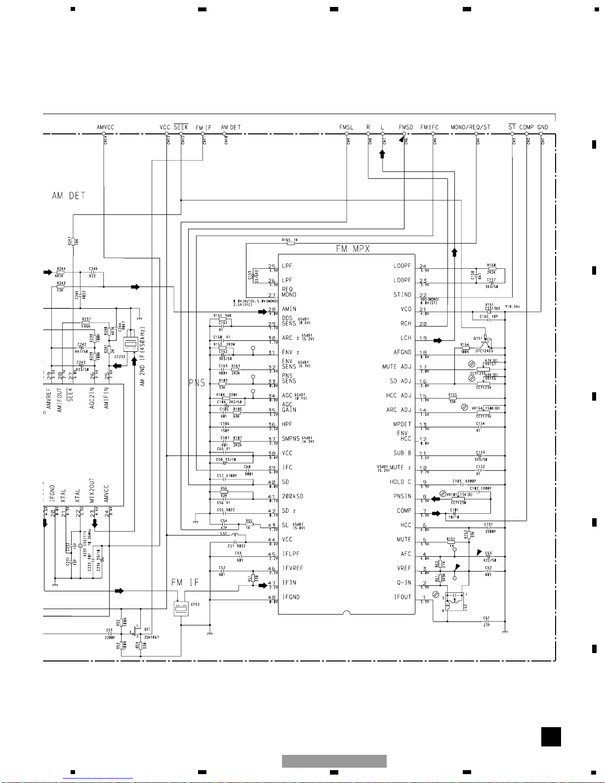
26
C
PA4023B
IC1
AM
FM
AM
FM
FM
FM
FM
FM
FM
FM
FM,AM
FM,AM
FM,AM
FM,AM
FM,AM
FM
FM
FM
AM
AM
AM
AM
AM
AM
AM
AM
AM
: FM SIGNAL
: AM SIGNAL
C
TUNER UNIT
A
1
234
12
34
F
E
D
C
B
A
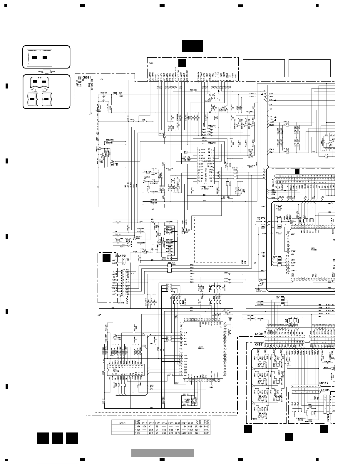
FX-M2137ZSA/X1B/UC
3.4 TUNER UNIT(FX-M2137ZSA/X1B/UC, FX-M2337ZSA/X1B/ES)
27
C
IC2 PA4024A
FM
FM
FM
FM
FM
FM,AM
FM,AM
FM,AM
AM
AM
AM
AM
AM
5
6
7
8
F
E
D
C
B
A
5
6
7
8
FX-M2137ZSA/X1B/UC

28
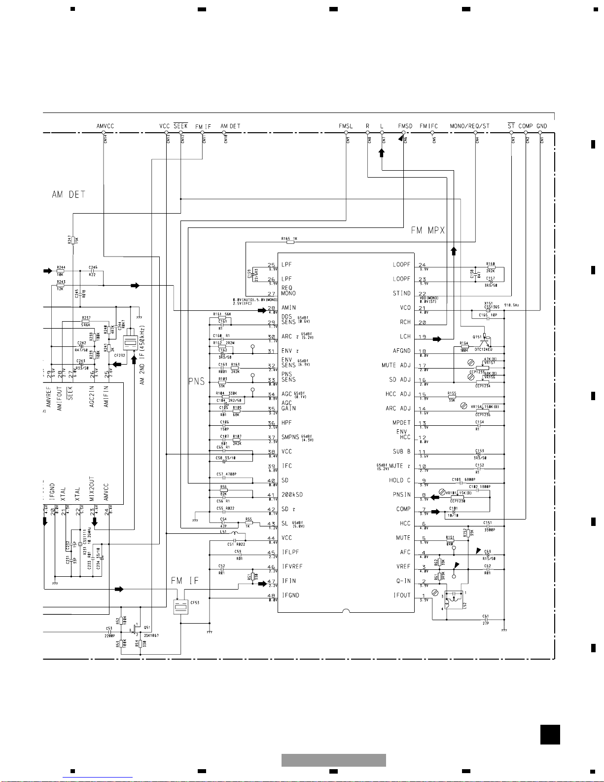
C
PA4023B
IC1
AM
FM
AM
FM
FM
FM
FM
FM
FM
FM
FM,AM
FM,AM
FM,AM
FM,AM
FM,AM
FM
FM
FM
AM
AM
AM
AM
AM
AM
AM
AM
AM
: FM SIGNAL
: AM SIGNAL
C
TUNER UNIT
A
1
234
12
34
F
E
D
C
B
A
FX-M2137ZSA/X1B/UC
3.5 TUNER UNIT(FX-M2037ZSA/X1B/EW)
29
C
IC2 PA4024A
FM
FM
FM
FM
FM
FM,AM
FM,AM
FM,AM
AM
AM
AM
AM
AM
5
6
7
8
F
E
D
C
B
A
5
6
7
8
FX-M2137ZSA/X1B/UC

30
G
M1 CXB6007
M2 CXB8933
LOADING/CARRIAGE
MOTOR
SPINDLE MOTOR
MOTOR DRIVER
3.3V
REGULATOR
Pickup Unit(Service)(P10)
F
T
F
T
F
T
T
F
F
F
T
T
F
T
S
C
F
F
T
T
S
S
C
C
S
S
C
C
T
T
F
F
F
F
T
T
1
7
8
3
6
5
@
9
0
!
#
1
234
12
34
F
E
D
C
B
A
FX-M2137ZSA/X1B/UC
3.6 CD MECHANISM MODULE
 Loading...