

Page 1
NETWORK CACHE CHANGER
DRM-6NX
THIS MANUAL IS APPLICABLE TO THE FOLLOWING MODEL(S) AND TYPE(S).
ORDER NO.
RRV2103
Type
Model
DRM-6NX
TUCYV O AC110 - 240V
Power Requirement
CONTENTS
1. SAFETY INFORMATION....................................2
2. EXPLODED VIEWS AND PARTS LIST .............4
3. SCHEMATIC DIAGRAM................................... 14
4. PCB CONNECTION DIAGRAM .......................26
5. PCB PARTS LIST.............................................32
6. ADJUSTMENT.................................................. 35
Remarks
7. GENERAL INFORMATION .............................. 45
7.1 IC................................................................ 45
7.2 DIAGNOSIS ...............................................46
7.2.1 DIAGNOSIS METHOD FOR MULTI
MECHA ASSY AND HDD................. 46
7.2.2 DISASSEMBLY................................. 46
7.2.3 TROUBLESHOOTING......................48
7.2.4 UPGRADING THE NETWORK
CACHE CHANGER .......................... 53
7.3 BLOCK DIAGRAM .................................... 56
8. PANEL FACILITIES AND SPECIFICATIONS
...................................................................57
PIONEER ELECTRONIC CORPORATION 4-1, Meguro 1-Chome, Meguro-ku, Tokyo 153-8654, Japan
PIONEER ELECTRONICS SERVICE, INC. P.O. Box 1760, Long Beach, CA 90801-1760, U.S.A.
PIONEER ELECTRONIC (EUROPE) N.V. Haven 1087, Keetberglaan 1, 9120 Melsele, Belgium
PIONEER ELECTRONICS ASIACENTRE PTE. LTD. 253 Allexandra Road, #04-01, Singapore 159936
c
PIONEER ELECTRONIC CORPORATION 1999
T – ZZY FEB. 1999 Printed in Japan
Page 2
DRM-6NX
1. SAFETY INFORMATION
This service manual is intended for qualified service technicians; it is not meant for the casual
do-it-yourselfer. Qualified technicians have the necessary test equipment and tools, and have been
trained to properly and safely repair complex products such as those covered by this manual.
Improperly performed repairs can adversely affect the safety and reliability of the product and may
void the warranty. If you are not qualified to perform the repair of this product properly and safely, you
should not risk trying to do so and refer the repair to a qualified service technician.
WARNING
This product contains lead in solder and certain electrical parts contain chemicals which are known to the state of California to cause
cancer, birth defects or other reproductive harm.
Health & Safety Code Section 25249.6 – Proposition 65
NOTICE
(FOR CANADIAN MODEL ONLY)
Fuse symbols (fast operating fuse) and/or (slow operating fuse) on PCB indicate that replacement parts
must be of identical designation.
REMARQUE
(POUR MODÈLE CANADIEN SEULEMENT)
Les symboles de fusible (fusible de type rapide) et/ou (fusible de type lent) sur CCI indiquent que les
pièces de remplacement doivent avoir la même désignation.
(FOR USA MODEL ONLY)
1. SAFETY PRECAUTIONS
The following check should be performed for the
continued protection of the customer and service
technician.
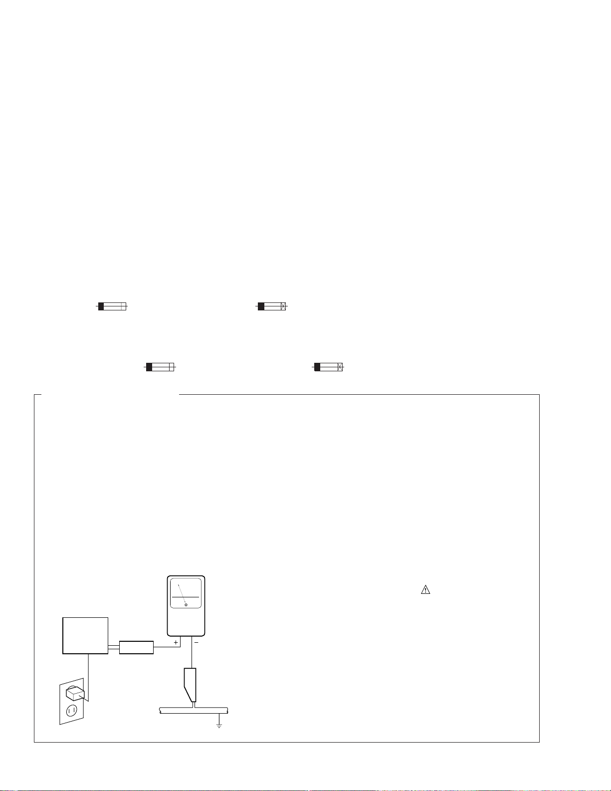
LEAKAGE CURRENT CHECK
Measure leakage current to a known earth ground
(water pipe, conduit, etc.) by connecting a leakage
current tester such as Simpson Model 229-2 or
equivalent between the earth ground and all exposed
metal parts of the appliance (input/output terminals,
screwheads, metal overlays, control shaft, etc.). Plug
the AC line cord of the appliance directly into a 120V
AC 60 Hz outlet and turn the AC power switch on. Any
current measured must not exceed 3.5 mA.
Reading should
not be above
3.5 mA
Earth ground
Device
under
test
Also test with plug
reversed
(Using AC adapter
plug as required)
Leakage
current
tester
Test all exposed
metal surfaces
AC Leakage Test
ANY MEASUREMENTS NOT WITHIN THE LIMITS
OUTLINED ABOVE ARE INDICATIVE OF A POTENTIAL SHOCK HAZARD AND MUST BE CORRECTED BEFORE RETURNING THE APPLIANCE
TO THE CUSTOMER.
2. PRODUCT SAFETY NOTICE
Many electrical and mechanical parts in the appliance have special safety related characteristics. These
are often not evident from visual inspection nor the
protection afforded by them necessarily can be obtained by using replacement components rated for
voltage, wattage , etc. Replacement parts which have
these special safety characteristics are identified in
this Service Manual.
Electrical components having such features are
identified by marking with a
on the parts list in this Service Manual.
The use of a substitute replacement component which
does not have the same safety characteristics as the
PIONEER recommended replacement one, shown in
the parts list in this Service Manual, may create shock,
fire, or other hazards.
Product Safety is continuously under review and
new instructions are issued from time to time. For
the latest information, always consult the current
PIONEER Service Manual. A subscription to, or additional copies of, PIONEER Service Manual may be
obtained at a nominal charge from PIONEER.
on the schematics and
2
Page 3
DRM-6NX
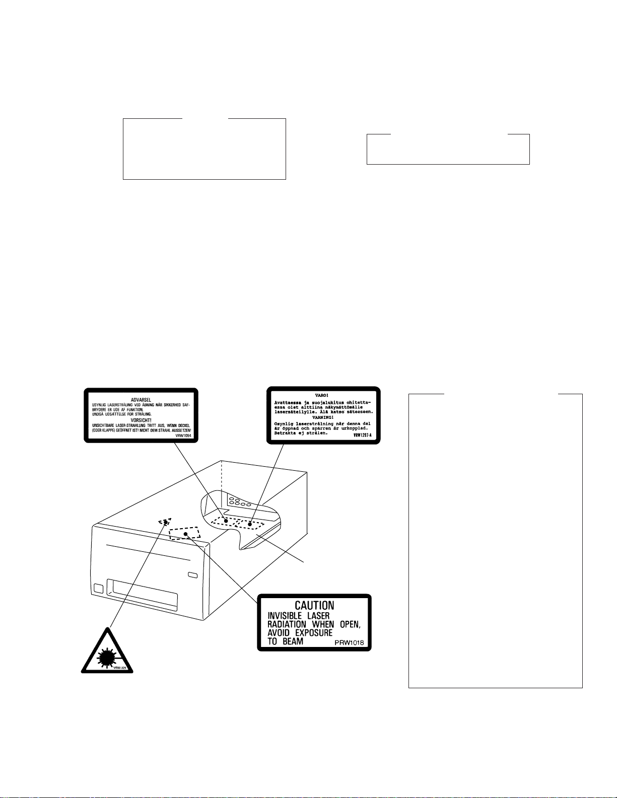
THIS PIONEER APPARATUS CONTAINS
LASER OF CLASS 1.
SERVICING OPERATION OF THE APPARATUS
SHOULD BE DONE BY A SPECIALLY
INSTRUCTED PERSON.
LABEL CHECK
IMPORTANT
LASER DIODE CHARACTERISTICS
MAXIMUM OUTPUT POWER: 5 mw
WAVELENGTH: 780 - 785 nm
Additional Laser Caution
(HDD Stay Assy Top) (HDD Stay Assy Top)
HDD Stay Assy
(Synchronize Lever Top)
(Holder Top)
1. Laser Interlock Mechanism
The ON/OFF (ON: low level, OFF: high
level) status of the LPS1 (S601) switch for
detecting the loading state is detected by
the system microprocessor, and the
design prevents laser diode oscillation
when LPS1 (S601) is not ON (low level)
(clamped srate).
Thus, interlock will no longer function if
switch LPS1 (S601) is deliberately
shorted.
In the test mode∗ the interlock mechanism
will not function.
Laser diode oscillation will continue, if pin 2
of AN8849SB (IC201) on the MAIN
BOARD assy is connected to GND, or else
the terminals of Q201 are shorted to each
other (fault condition).
2. When the cover is opened with the servo
mechanism block removed to be turned
over, close viewing of the objective lens
with the naked eye will cause exposure to
a Class 1 laser beam.
∗ Refer to page 36.
3
Page 4
DRM-6NX
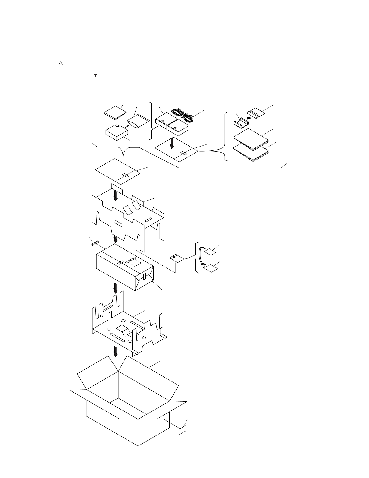
2. EXPLODED VIEWS AND PARTS LIST
NOTES:• Parts marked by "NSP" are generally unavailable because they are not in our Master Spare Parts List.
2.1 PACKING
The mark found on some component parts indicates the importance of the safety factor of the part.
•
Therefore, when replacing, be sure to use parts of identical designation.
Screws adjacent to mark on the product are used for disassembly.
•
6
9
2
1
3
7
4
18
2
15
11
FRONT
14
12
10
17
8
5
13
16
4
Page 5

PACKING PARTS LIST
•
Mark No. Description Parts No.
1 Power Cable (for U.S.and Canada) DDG1071
2 6-Disc Magazine DXA1864
3 Power Button Cover DNK3626
4 Operating Instructions DRB1239
(English)
5 Operating Instructions DRB1243
(German)
DRM-6NX
NSP 7 Polyethylene Bag Z21-002
NSP 8 Polyethylene Bag Z21-006
NSP 16 Label VRW1629
NSP 17 Network Board
6 Label DRW1928
9 Polyethylene Bag Z21-014
(165 × 200 × 0.03)
10 Polyethylene Bag Z21-038
(0.03 × 230 × 340)
11 Pad A DHA1421
12 Pad B DHA1422
13 Packing Case DHG1879
14 Sheet DHL-125
15 Polyethylene Bag DHL1020
Serial Number Label ••••••••
18 SCSI Connector Cover FCN-780C050-14
5
Page 6
DRM-6NX
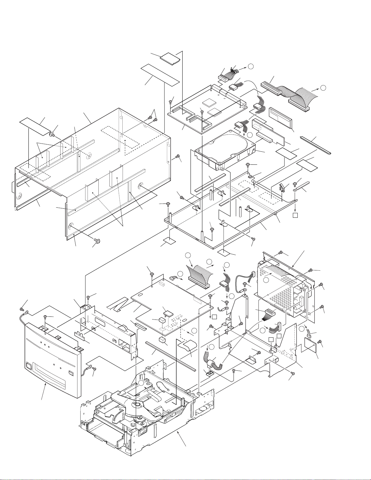
2.2 EXTERIOR (1/2)
35
24
26
22
44
10
24
37
28
23
22
29
10
25
35
34
26
49
4
42
39
43
40
A
41
D
36
3
33
36
12
B
21
5
6
48
47
46
34
18
34
33
17
11
31
34
23
34
12
B
14
30
Refer to "2.5 Rear
34
B
34
Panel Section".
F
8
2
27
34
34
34
34
19
D
32
F
E
B
32
45
1
15
G
20
13
7
38
A
34
A
9
16
G
11
19
E
38
C
39
34
40
C
A
34
35
Refer to "2.4 Front Panel
Section".
6
Refer to "2.3 EXTERIOR (2/2)".
Page 7

EXTERIOR (1/2) PARTS LIST
•
Mark No. Description Part No.
DRM-6NX
Mark No. Description Part No.
1 MAIN BOARD ASSY DWX1906
2 IDSB BOARD ASSY DWZ1084
3 AXIS NETWORK BOARD ASSY DWN1001
4 MEMORY BOARD ASSY (16MB)DWX1916
5 IDE/SCSI BOARD ASSY DWX1917
6 Hard Disk DXX2434
7 Lead Card 30P DDD1121
8 Connector Assy DKP3416
NSP 9 Ferrite Clamp DTH1174
10 Screw DBA1083
11 Screw (#6-32) DBA1125
12 Cushion DEB1405
13 Barrier Packin A DEB1417
14 Barrier Packin B DEB1418
15 PCB Cushion (T8) DEB1420
16 F Clamp Holder DEC1266
NSP 17 Locking Wire Saddle DEC1305
NSP 18 Edging Saddle (S) DEC1761
19 Sheet DEC1939
20 PCB Cushion (T10) DEC2190
21 Sheet DEC2260
22 Bonnet Packin A DEC2290
23 Bonnet Packin B DEC2291
24 Bonnet Packin C DEC2292
25 Plate DEC2299
NSP 27 Chassis (S) DNA1238
26 Bonnet Sheet DEC2300
NSP 28 Front Stay DND1213
29 Bonnet DNE1365
30 HDD Stay Assy DXB1695
31 Cord Clamper RNH-184
32 Screw ABZ30P080FCC
33 Screw BBT30P060FNI
34 Screw BBT30P060FZK
35 Screw BBZ30P050FMC
36 Screw BMZ30P060FNI
37 Screw IBZ30P060FMC
38 Screw PMB40P080FMC
39 Connector 20P DKP3419
40 Connector 4P DKP3415
41 Connector 50P DKP3417
42 Binder ZCA-SKB90BK
43 65 Label ARW7050
44 Label DRW1533
45 Heat Sink DNE1352
NSP 46 Coution Label HE VRW1297
47 Coution Label VRW1094
NSP 48 Sheet VEX1023
49 Tape (G) REH1010
7
Page 8
DRM-6NX
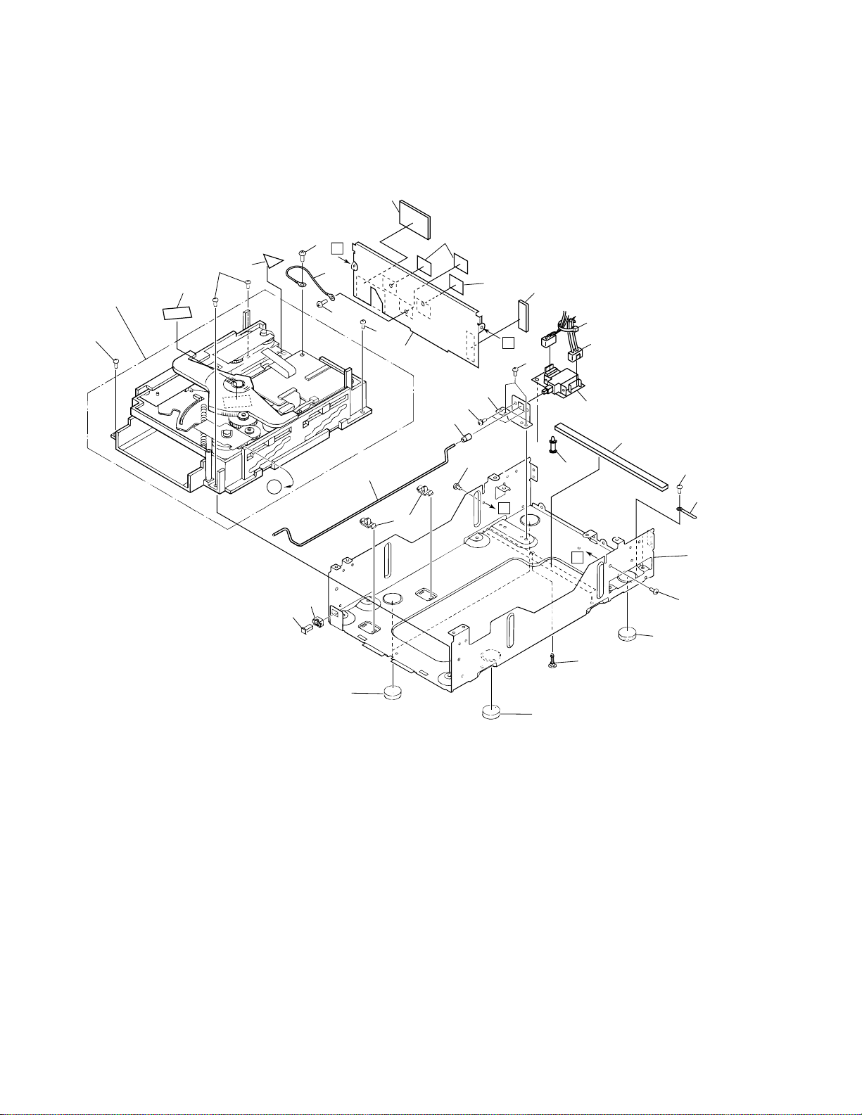
2.3 EXTERIOR (2/2)
7
Refer to
"2.6 MULTI
MECHA ASSY".
12
24
21
24
20
24
B
2
23
24
10
B
17
18
14
16
11
13
25
22
15
11
6
27
A
23
B
26
1
5
3
A
23
19
9
22
8
4
8
8
8
Page 9

EXTERIOR (2/2) PARTS LIST
•
Mark No. Description Part No.
DRM-6NX
NSP 2 Cord With Plug DE005VF0
NSP 3 PCB Spacer(3 x 12) AEC1372
NSP 9 Base Chassis DNA1177
NSP 11 Sheet E VEX1006
NSP 12 Multi Mchanism Assy DXB1653
1 PWSB BOARD ASSY DWS1296
4 Locking Card Spacer DEC1858
5 Barrier Packin C DEC2302
6 Barrier Packin D DEC2303
7 Barrier Packin E DEC2304
8 Leg DED1102
10 Barrier DNH2299
13 Joint Cap DEB1057
14 PSW Joint DLA1658
15 SW Holder DNF1500
16 Shaft Holder DNK2414
17 PSW Bush DNK1326
18 PSW Cap DNK2413
19 Cord Clamper RNH-184
20 Coution Label G VRW-329
21 Coution Lavel PRW1018
22 Screw BBT30P060FZK
23 Screw BBZ30P050FMC
24 Screw BBZ30P080FMC
25 Screw PMA30P060FMC
26 Connector Assy 2P DKP3426
27 Binder ZCA-SKB90BK
9
Page 10
DRM-6NX
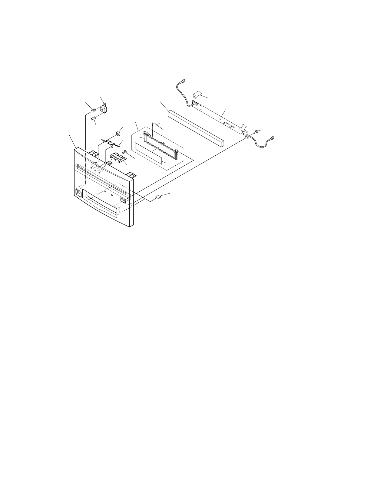
2.4 FRONT PANEL SECTION
6
3
16
9
3
17
7
4
14
8
5
11
2
13
12
1
14
FRONT PANEL SECTION PARTS LIST
•
Mark No. Description Part No.
NSP 2 Door Name Plate DAM1078
NSP 7 Door DNK3112
1 FRPB BOARD ASSY DWZ1083
3 Power Button Spring DBH1213
4 Reflector DEC2283
5 Front Packin DEC2301
6 Power Button DNK2411
8 Indicater Lens DNK3624
9 Front Panel Assy DXA1861
10 ••••••••
11 Door Spring PBH1022
12 12P F. F. C/30V DDD1097
13 Tape (G) REH1010
14 Screw IPZ30P080FMC
15 ••••••••
16 Door Assy-S DXX2403
17 Nat YP20FBT
10
Page 11
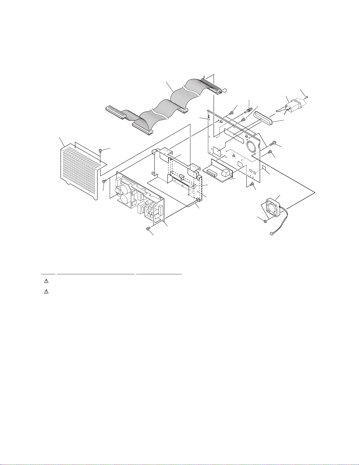
2.5 REAR PANEL SECTION
DRM-6NX
5
19
3
20
4
18
8
20
20
20
REAR PANEL SECTION PARTS LIST
•
Mark No. Description Part No.
1 PWRB BOARD ASSY DWR1307
3 AC Inlet Assembly 3P DKN1148
2 CONNECTOR BOARD ASSY DWX1921
4 Ground Terminal DKE-102
5 Connector Assy 50P DKP3417
11
10
17
15
20
2
24
14
16
7
13
12
21
1
6 ••••••••
7 DC Fan motor VXM1069
NSP 8 Power Cover DNH2426
9 ••••••••
10 SCSI Connector Cover FCN-780C050-14
11 Rear Panel DNC1499
NSP 12 Power Stay DND1215
13 Coner Cover DEC2315
14 Rear Packin A DEC2313
15 Rear Packin B DEC2314
16 Screw BMZ30P060FNI
17 Screw AMZ40P160FZK
18 Screw PMZ30P100FNI
19 Screw CBZ30P080FZK
20 Screw BBT30P060FZK
21 Nut NB40FMC
22 ••••••••
23 ••••••••
24 ID SW Cover DEC2269
11
Page 12
DRM-6NX
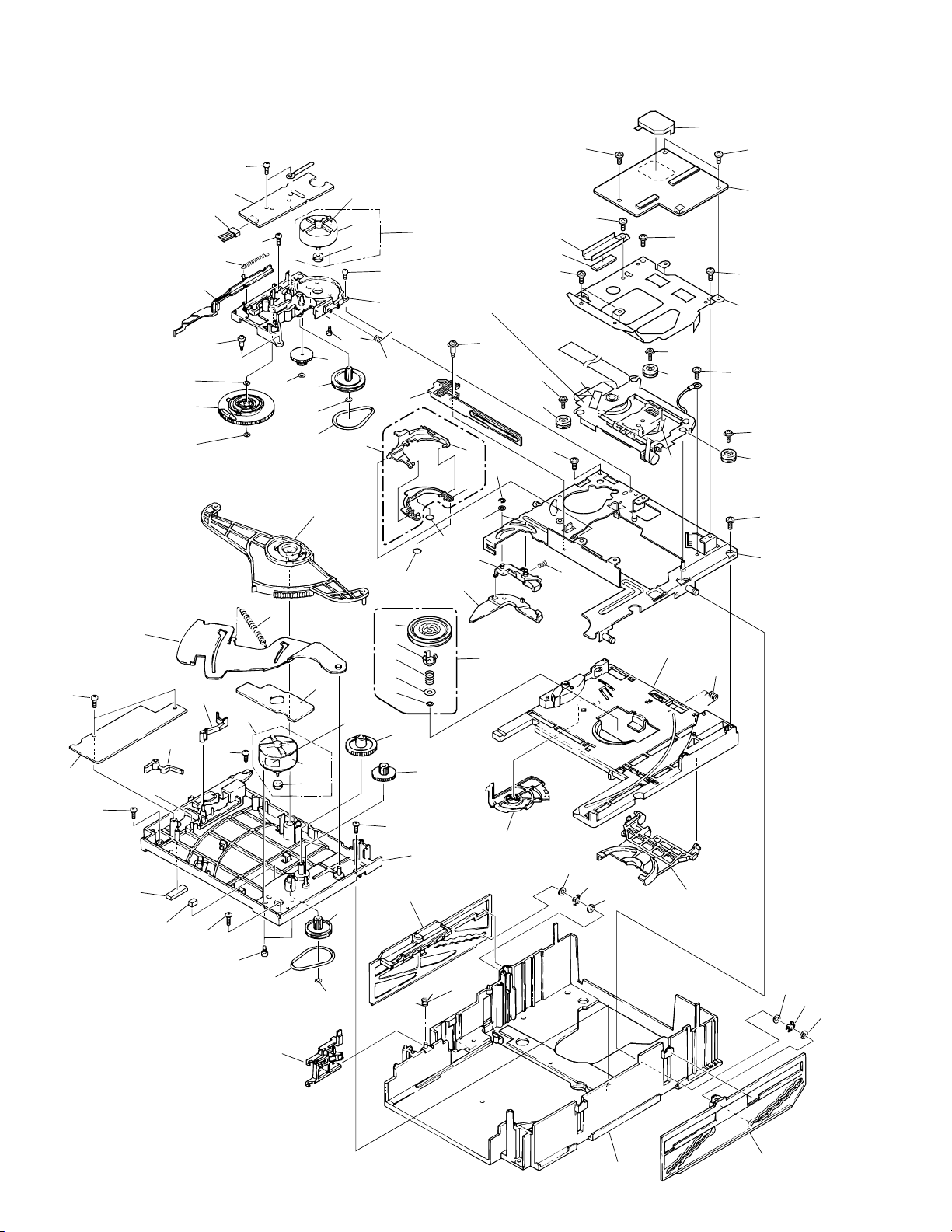
2.6 MULTI MECHA ASSY
38
63
57
38
26
25
17
38
66
60
11
41
4
40
12
38
40
10
36
40
7
5
59
1
35
67
∗1 Label
59
1
37
9
68
∗2 Label
36
39
Refer to
"2.7 SERVO MECHA
2
ASSY".
18
16
20
20
30
53
29
55
54
8
15
9
19
13
21
41
62
17
52
42
48
49
38
51
50
39
69
14
70
39
23
64
48
49
71
69
3
39
39
56
39
48
49
43
61
58
12
38
45
44
38
37
5
31
40
38
6
33
7
32
27
47
46
47
65
28
34
47
46
47
Page 13
MULTI MECHA PARTS LIST
•
Mark No. Description Parts No.
1 Motor Pulley PNW1634
2 Gear Holder PNW1929
3 SIFB BOARD ASSY DWZ1081
4 Cam Gear PNW1923
5 Belt PEB1138
6 Top Guide N PNW2441
7 Gear Pulley PNW1918
8 Gear S PNW1919
9 Gear L PNW1920
10 Eject Spring PBH1107
11 SW Lever PNW1927
12 Seven Bar PNW1931
13 Sub Revolving Lever PNW1933
14 Sub Revolving Lever Spring PBH1111
15 Revolving Lever PNW1932
16 Drive Plate DNK3450
17 Motor Screw PBA–112
18 Holder Lever Spring PBH1110
19 Disc Holder DNK3448
20 Cushion DED1111
21 Holder Lever DNK3449
22 ••••••••
23 S Flexible Wire DNP1748
24 ••••••••
25 Release Lever PNW1934
26 Release Spring PBH1106
27 Clamper Cam PNW1922
28 Clamper Holder PNW1921
29 Centering Spring DBH1389
30 Clamper Assy DXB1651
31 Lock Lever PNW1917
32 Lock Spring PBH1108
33 Stair NL PNW2443
34 Stair NR PNW2444
35 Synchronize Lever PNW1926
DRM-6NX
Mark No. Description Parts No.
36 Motor Assy PEA1130
(LOADING, DISC SELECT)
37 Screw PMZ26P040FMC
38 Screw PPZ30P080FMC
39 Screw BBZ30P060FMC
40 Washer WT26D047D025
41 Washer WA31D054D025
42 E Ring Z39–010
43 Screw IPZ30P080FMC
44 Spacer PEB1254
45 Spacer PEB1179
46 Silent Ring PBK1093
47 Washer WA62D130D025
48 Screw AMZ26P040FMC
49 Mount Bush 24 DEB1357
50 F Cushion C DEB1151
51 Hold Plate RNE1629
52 Clamper Assy S DXX2391
53 Centering Arm DNK3451
54 Washer WT21D060D025
55 Washer WA26D080D025
56 Holder DNH2297
57 Connector Assy (4P) PG04MM–F07
58 Clamp Spring PBH1109
59 Carriage Motor VXM1033
60 Eject Lever PNB1306
61 Mechanism Base DNH2305
62 Servo Mechanism Assy DXB1654
NSP 63 LOAD BOARD Assy PWZ2038
64 Sub Chassis N PNW2440
65 Main Chassis PNW2074
NSP 66 DSEL BOARD Assy PWZ2533
NSP 67 MOTB BOARD Assy PWZ2040
68 Hold Plate Assy DXB1662
69 Screw BBZ30P080FMC
70 Damp Sheet VEX1021
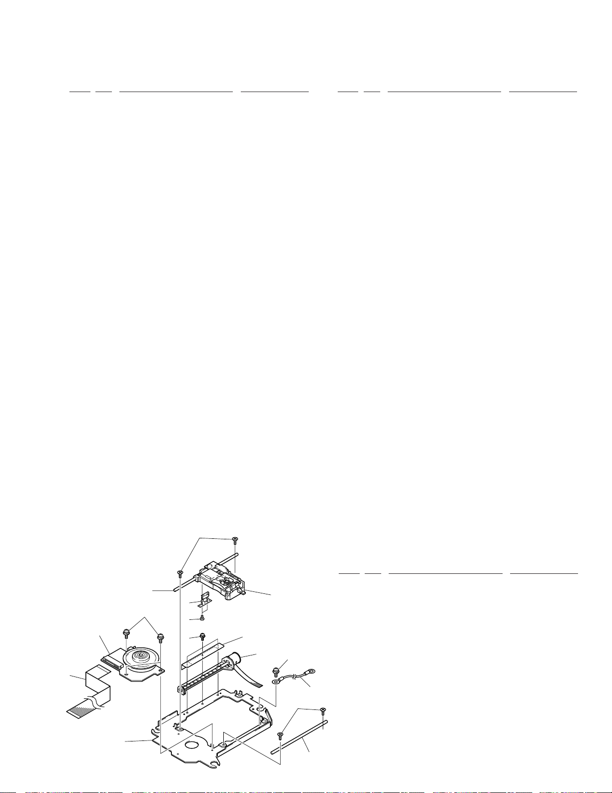
2.7 SERVO MECHA ASSY
6
7
14
1
11
10
2
9
4
71 Shield Case DNH2292
SERVO MECHA ASSY PARTS LIST
•
Mark No. Description Parts No.
1 Spindle Motor Assy DXM1097
12
5
3
14
NSP 10 Servo Mechanism Base DNH2302
13
6
NSP 12 Pickup Assy DWY1069
2 Screw Guide DNK3238
3 Pulse Motor Frame DXM1096
4 Screw PMH20P040FMC
5 Cover Plate DBK1138
6 Screw CMZ20P060FMC
7 Guide Shaft DLA1731
8 Sub Guide Shaft DLA1372
9 Screw ABA7022
11 SPD Card DDD1122
13 Earth Lead Unit PDF1074
14 Screw AMZ20P040FCC
8
13
Page 14
1
234
DRM-6NX
3. SCHEMATIC DIAGRAM
Note: When ordering service parts, be sure to refer to "EXPLODED VIEWS AND PARTS LIST" or "PCB PARTS LIST".
A
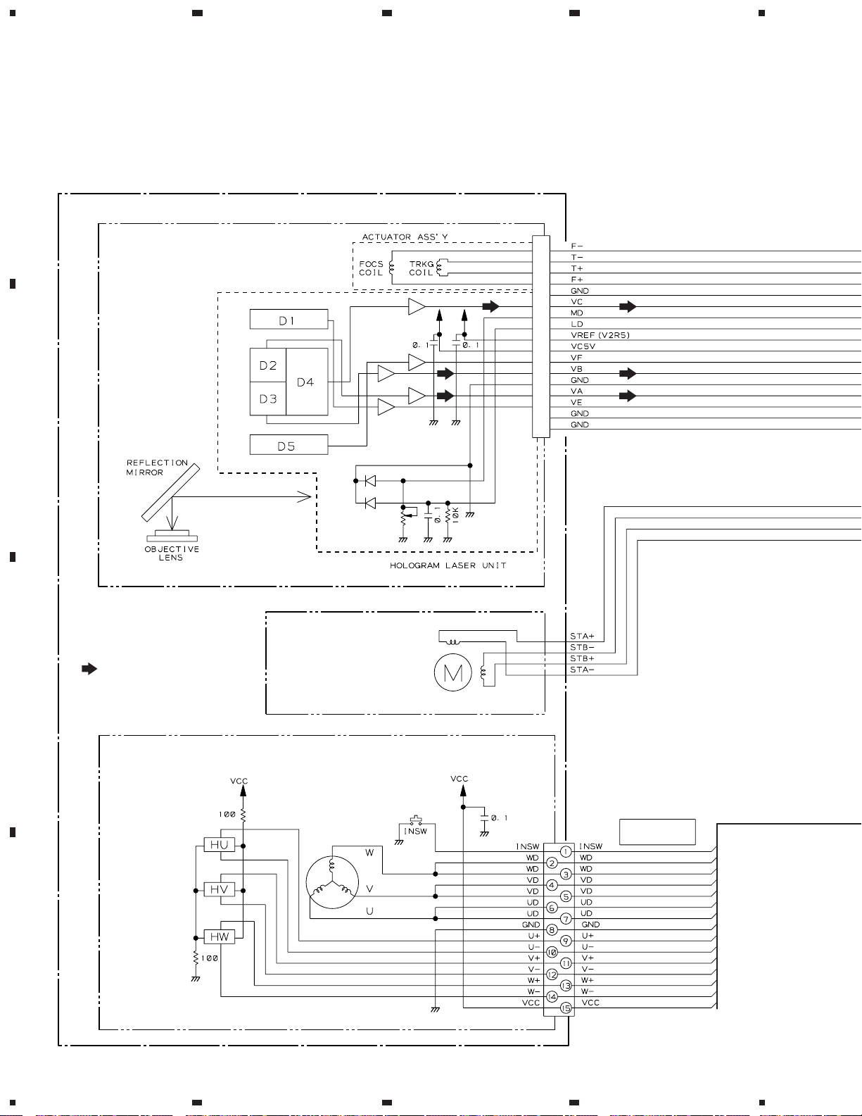
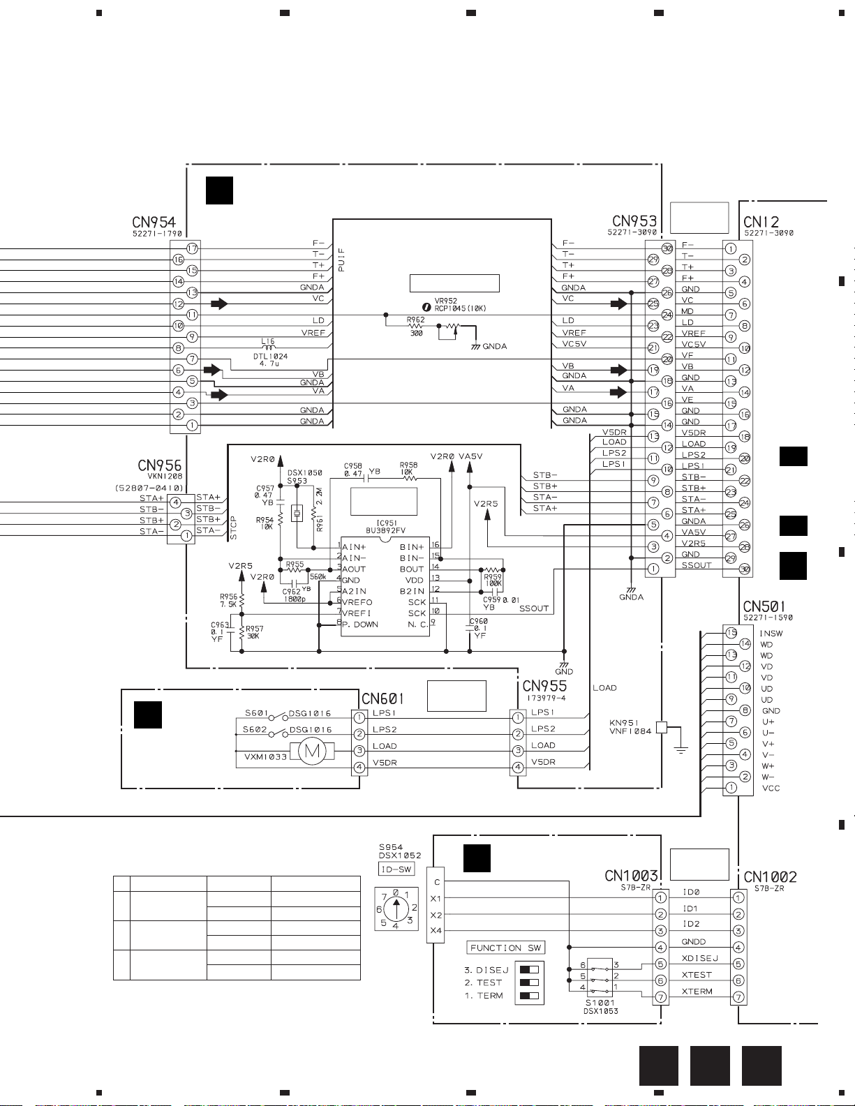
3.1 OVERALL CONNECTION DIAGRAM (1/2)
(SIFB BOARD ASSY, LOAD BOARD ASSY and IDSB BOARD ASSY)
SERVO MECHANISM ASSY (DXB1654)
PICKUP ASSY
(DWY1069)
B
SIGNAL ROUTE
: RF & AUDIO SIGNAL ROUTE
C
PULSE MOTOR FRAME
(DXM1069)
STEPPING MOTOR
SPINDLE MOTOR
(DXM1097)
FLEXIBLE CORD
DDD1122
D
14
1234
Page 15
5
67
8
DRM-6NX
A
SIFB BOARD ASSY (DWZ1081)
A
LD POWER ADJ.
FLEXIBLE
CORD
DDD1121
MAIN BOARD ASSY
(DWX1906)
B
)
B
LOAD BOARD
ASSY
(PWZ2038)
S1001 (FUNCTION SW)
No.
1
TERMINATION
2
TEST
3
DISABLE EJECT
DIP SW MODE SETTING
ON (SHORT) TERMINATOR ON
OFF (OPEN) TERMINATOR OFF
ON (SHORT) TEST MODE ON
OFF (OPEN) TEST MODE OFF
ON (SHORT) EJECT ENABLE
OFF (OPEN) EJECT DISABLE
VIBRATION
SENSOR
CONNECTOR
ASSY
PG04MM-F07
C
IDSB BOARD ASSY
(DWS1084)
CONNECTOR
ASSY
DKP3416
D 1/3 to D 3/3
(
D
C
D
CBA
5
6
7
8
15
Page 16
1
234
DRM-6NX
3.2 OVERALL CONNECTION DIAGRAM (2/2)
(FRPB BOARD ASSY, MOTB BOARD ASSY, DSEL BOARD ASSY,
PWSB BOARD ASSY, PWRB ASSY, IDE/SCSI BOARD ASSY,
A
B
C
AXIS NETWORK BOARD ASSY, MEMORY BOARD ASSY and
CONNECTOR BOARD ASSY)
FRPB BOARD ASSY
E
(DWZ1083)
N. C.
N. C.
FLEXIBLE
CORD
DDD1097
D
PEA1130
MOTB BOARD
F
ASSY (PWZ2040)
(
D
1/3 to
S952: EJECT
D
EJECT
L951–L956:
RTF1167
MAIN BOARD ASSY
)
3/3
(DWX1906)
CHANGER POWER
S603:Magazine
(Existence/None)
S604: Multi/Single
DSEL BOARD
G
ASSY (PWZ2533)
Magazine
(Existence/None)
Multi/Single
PSG1010
DSG1016
DSG1016
DSG1016
Magazine IN
Single
1: GND
3: GND
5: GND
7: GND
9: GND
11: GND
13: GND
15: GND
17: GND
19: GND
21: GND
23: OPEN
25: OPEN
27: OPEN
29: GND
31: GND
33: GND
35: GND
37: GND
39: GND
41: GND
43: GND
45: GND
47: GND
49: GND
2: DB0
4: DB1
6: DB2
8: DB3
10: DB4
12: DB5
14: DB6
16: DB7
18: DBP
20: GND
22: GND
24: OPEN
TERMPWR
26:
28: OPEN
30: GND
32: ATN
34: GND
36: BSY
38: ACK
40: RST
42: MSG
44: SEL
46: C/D
48: REQ
50: I/O
Test Remote Control
(RU-V101) Interface
D
16
1234
GFE
Page 17
5
67
8
DRM-6NX
CONNECTOR
JP5, JP11: Short
JP1
2: GND
4: GND
6: GND
8: GND
10: GND
12: GND
14: GND
1: JP1
3: JP2
5: JP3
7: JP4
9: JP5
11: JP6
13: JP7
IDE/SCSI BOARD ASSY
M
(DWX1917)
Note: As this circuit board is
an assembly purchase part,
no circuit diagram is listed.
16: GND
15: JP8
18: GND
17: JP9
JP11
20: GND
19: JP10
22: GND
21: JP11
1: RESET
3: DB7
5: DB6
7: DB5
9: DB4
11: DB3
13: DB2
15: DB1
17: DB0
19: GND
21: OPEN
23: DIOW
25: DIOR
27: IORDY
29: OPEN
31: INTRQ
33: DA1
35: DA0
37: CS1FX
39: OPEN
2: GND
4: DB8
6: DB9
8: DB10
10: DB11
12: DB12
14: DB13
16: DB14
18: DB15
20: OPEN
22: GND
24: GND
26: GND
28: OPEN
30: GND
32: OPEN
34: OPEN
36: DA2
38: CS3FX
40: GND
ASSY 50P
DKP3417
HARD
DISK
UNIT
(DXB1696)
SCSI
I/F
A
B
J
I
PWRB ASSY
(DWR1307)
STATUS DRIVE NETWORK
AXIS NETWORK
BOARD ASSY
(DWN1001)
Note: As this circuit board is
an assembly purchase part,
no circuit diagram is listed.
MEMORY BOARD
K
ASSY (DWX1916)
Note: As this circuit board is
an assembly purchase part,
no circuit diagram is listed.
CONNECTOR
ASSY
DKP3426
L (BRN)
N (BLU)
16MB
72pin
DIMM
L (BRN)
N
(BLU)
CONNECTOR
ASSY 4P
CONNECTOR
ASSY 20P
DKP3419
DKP3415
CONNECTOR
L
BOARD ASSY
(DWX1917)
Note: As this circuit board is
an assembly purchase part,
no circuit diagram is listed.
AC POWER CORD
DDG1071
(AC110-240V)
C
D
PWSB BOARD ASSY
H
(DWS1296)
JH
5
6
7
MLK
8
17
Page 18
1
234
DRM-6NX
3.3 MAIN BOARD ASSY (1/3) and
PWRB ASSY
CN3, HARD DISK UNIT,
M
J
A
PWRB ASSY (DWR1307)
I
C950
H
NOTE FOR FUSE REPLACEMENT
CAUTION: FOR CONTINUED PROTECTION
:This schematic diagrm is reference
information When it is repaired please
cope by assy exchange.
B
AGAINST RISK OF FIRE.
REPLACE WITH SAME
TIME AND RATINGS ONLY.
C
POWER SUPPLY
1
VIN
2
ON
IC111
PQ7VZ5
VOUT
/OFF
OADJ
5
3.3V REG.
3
4
D 1/3
MAIN BOARD
ASSY (1/3)
(DWX1906)
A
2/3
D
D
18
D 1/3
1234
CAUTION: FOR CONTINUED PROTECTION AGAINST RISK OF FIRE.
REPLACE ONLY WITH SAME TYPE NO. ICP–S2.3, MFD
BY ROHM CO., LTD. FOR IC24.
I
CAUTION: FOR CONTINUED PROTECTION AGAINST RISK OF FIRE.
REPLACE ONLY WITH SAME TYPE NO. ICP–S1.0, MFD
BY ROHM CO., LTD. FOR IC23.
Page 19

5
67
8
DRM-6NX
SIGNAL ROUTE
: RF SIGNAL ROUTE
A
CN1003
C
Q11, Q15:
DISC SELECT
MOTOR DRIVER
CN952
E
B
Q17, Q18:
LOADING MOTOR
DRIVER
STEPPING
MOTOR DRIVER
CN953
C
A
D
CN1, SCSI I/F
M
5
J
D 1/3
6
7
8
19
Page 20

1
DRM-6NX
3.4 MAIN BOARD ASSY (2/3)
A
B
3/3
D
234
B
Interface
TEST REMOTE CONTROL (RU-V101)
C
MB90T553PF
CPU
PD6287B
FLASH
ROM
1 Mbit DRAM
D
SCSI
TERMINATOR
20
D 2/3
1234
Page 21

5
67
8
DRM-6NX
A
B
CD-ROM DECODER
&
SCSI I/F
C
A
1/3
D
D
EEPROM
D
5
MAIN BOARD ASSY (2/3)
2/3
(DWX1906)
6
SIGNAL ROUTE
: RF SIGNAL ROUTE
7
D 2/3
8
21
Page 22

1
234
DRM-6NX
3.5 MAIN BOARD ASSY (3/3)
A
D
MAIN BOARD ASSY (3/3)
3/3
(DWX1906)
IC204: TRACKING SERVO
EQUALIZER SW
5V REG.
IC201 (AN8849SB)
Voltage [ V ]
Pin No.
B
0
1
4.6
2
2.5
3
5
4
2.5
5
1.4
6
3.5
7
2.5
8
3.2
9
1.9
10
3
11
1.8
12
3.6
13
0
14
3.6
15
0
16
4.9
17
0
18
0
19
2.5
20
2.2
21
22
|
1.8
27
0.9
28
1.8
29
1.8
30
31
|
2.5
36
3
4
HEAD
AMP
Q202:RF EQUALIZER
SW for CD-RW
1
2
IC451 (M56759FP)
Voltage [ V ]
Pin No.
12.4
1
2.5
2
0.3
3
1.2
4
2.1
5
12.4
6
0.6
7
0.3
8
0.1
9
0
10
0
C
ACTUATOR
&
LOADING MOTOR
DRIVER
11
0.1
12
0.1
13
0.2
14
IC452: TRACKING SERVO
EQUALIZER SW
Pin No.
15
16
17
18
19
20
22 0
22
23
24
25
26
27
Voltage [ V ]
12.4
0.2
0.6
0.6
1.5
0.6
0
5
0
0
5
2.5
Pin No.
28
|
31
32
33
34
35
36
37
38
39
40
41
42
Voltage [ V ]
0.6
0
0
0.2
0.2
0.8
1.3
2.1
0
0
5
3.7
6
D
IC501 (AN8480SBB)
Voltage [ V ]
Pin No.
0
1
2.5
2
2.5
3
0
4
2.6
5
2.25
6
0.3
7
2.65
8
Voltage [ V ]
Pin No.
9
10
11
12
13
|
15
16 4.95
17 1.74
2.65
4.95
4.95
Voltage [ V ]
Pin No.
1.74
18
0
19
0
0
0.23
20
12.3
21
12.3
22
23
0
|
28
22
D 3/3
1234
Page 23

IC282: RESET
5
67
8
DRM-6NX
SIGNAL ROUTE
B
2/3
D
A
B
: RF SIGNAL ROUTE
MN662752CDM1
DIGITAL SERVO
PROCESSOR
SPINDLE
DRIVER
5
C
To SPINDLE MOTOR
5
D
D 3/3
6
7
8
23
Page 24

DRM-6NX
Waveforms of MAIN BOARD Assy
1 RF – TP
0.2V/div., 0.5 µS/div.
× 1 PLAY
1 RF – TP
0.2V/div., 50 nS/div.
× 12 PLAY
1 RF – TP
0.2V/div., 20 nS/div.
× 24 PLAY
– 2.1V
– 2.1V
– 2.1V
2 AGC RF – TP
0.2V/div., 20 nS/div.
× 24 PLAY
– 1.65V
3 FE – TP
0.5V/div., 2 mS/div.
FOCUS IN
– GND
3 FE – TP
0.5V/div., 2 mS/div.
FOCUS
UP/DOWN
2 AGC RF – TP
0.2V/div., 0.5 µS/div.
× 1 PLAY
2 AGC RF – TP
0.2V/div., 50 nS/div.
× 12 PLAY
– GND
4 TE – TP
0.5V/div., 500 µS/div.
× 12 MULTI TRACK
JUMP (FWD)
– 1.65V
– GND
4 TE – TP
0.5V/div., 500 µS/div.
× 12 MULTI TRACK
JUMP (REV)
– 1.65V
– GND
24
Page 25

4
TE – TP
0.5V/div., 500 µS/div.
× 1 STILL
4
TE – TP
0.5V/div., 200 µS/div.
× 12 STILL
– GND
– GND
4
CH1: TE – TP
0.5V/div., 20 mS/div.
6
CH2: HK – TP
1V/div., 20 mS/div.
× 12 SEARCH
(REV)
(40=20 min.)
4
CH1: TE – TP
0.5V/div., 100 mS/div.
5
CH2: EC – TP
2V/div., 100 mS/div.
× 12 SEARCH
(FWD FULL STROKE)
4
6
4
5
DRM-6NX
GND
(CH1)
–
GND
(CH2)
–
GND
(CH1)
–
–
GND
(CH2)
4
CH1: TE – TP
0.5V/div., 5 mS/div.
5
CH2: EC – TP
1V/div., 5 mS/div.
× 12 PLAY
(CAV)
4
CH1: TE – TP
0.5V/div., 5 mS/div.
5
CH2: EC – TP
1V/div., 5 mS/div.
× 24 PLAY
(CLV)
4
CH1: TE – TP
0.5V/div., 20 mS/div.
6
CH2: HK – TP
1V/div., 20 mS/div.
× 12 SEARCH
(FWD)
(20=40 min.)
4
5
4
5
4
6
–
–
–
–
–
–
GND
(CH1)
GND
(CH2)
GND
(CH1)
GND
(CH2)
GND
(CH1)
GND
(CH2)
4
CH1: TE – TP
0.5V/div., 100 mS/div.
5
CH2: EC – TP
2V/div., 100 mS/div.
× 12 SEARCH
(REV FULL STROKE)
4
CH1: TE – TP
0.5V/div., 50 mS/div.
6
CH2: HK – TP
1V/div., 50 mS/div.
× 12 SEARCH
(FWD FULL STROKE)
4
CH1: TE – TP
0.5V/div., 50 mS/div.
6
CH2: HK – TP
1V/div., 50 mS/div.
× 12 SEARCH
(REV FULL STROKE)
4
5
4
6
4
6
–
–
–
–
–
–
GND
(CH1)
GND
(CH2)
GND
(CH1)
GND
(CH2)
GND
(CH1)
GND
(CH2)
25
Page 26

1
234
DRM-6NX
4. PCB CONNECTION DIAGRAM
4.1 SIFB BOARD ASSY, LOAD BOARD ASSY and
A
MAIN BOARD ASSY
B
LOAD BOARD ASSY
To PICKUP ASSY
PWZ2038 -A
SIFB BOARD ASSY
A
(PNP1331-A)
CN601
S601
S601
S602
S602
PNZ1489-A
D
To FAN MOTOR
MAIN BOARD ASSY
B
To STEPPING
MOTOR
C
IC17
IC18
IC19
VR952
IC951
(DNP1882–C)
NOTE FOR PCB DIAGRAMS:
1. Part numbers in PCB diagrams match those in the schematic
diagrams.
2. A comparison between the main parts of PCB and schematic
diagrams is shown below.
Symbol in PCB
Diagrams
BCE
D
BCE
DGS
Symbol in Schematic
Diagrams
BCE
BCEBCE
DGSDGS
26
1234
BCE
DBA
Part Name
Transistor
Transistor
with resistor
Field effect
transistor
Symbol in PCB
Diagrams
3. The parts mounted on this PCB include all necessary parts
for several destination.
For further information for respective destinations, be sure
to check with the schematic diagram.
4. Viewpoint of PCB diagrams
P. C. Board Chip Part
Symbol in Schematic
Diagrams
CapacitorConnector
Part Name
Resistor array
3-terminal
regulator
SIDE A
SIDE B
To SPINDLE
MOTOR
Page 27

5
67
8
DRM-6NX
SIDE A
CONNECTOR ASSY 4P
I
M J
CN2
CN3
To HARD DISK UNIT
CONNECTOR ASSY 50P
J M
CN1
SCSI I/F
IC24
IC282
IC205
IC20
IC411
Q411
IC21
IC451
Q201
C
CN1003
Q1003
Q1002
Q1001
IC23
IC802
Q621
IC801
Q622
IC702
IC101
IC703
IC301
IC302
Q13
IC704
Q11
Q14
Q12
IC452
IC701
Q15
IC12
IC232
A
Q21
B
Test Remote
Control Interface
(DNP1882–C)
E
CN952
IC201
Q202
Q18
IC16
Q22
IC204
IC231
IC15
Q16
Q17
IC11
IC705
IC706
Q19
Q651
Q652
IC13
Q20
C
D
D
5
6
7
8
27
Page 28

DRM-6NX
A
B
1
D
MAIN BOARD ASSY
234
SIDE B
C
(DNP1882–C)
D
28
D
1234
Page 29

5
67
8
DRM-6NX
A
SIDE B
SIFB BOARD ASSY
A
B
C
(DNP1882–C)
D
DA
5
6
7
8
29
Page 30

1
234
DRM-6NX
4.2 IDSB BOARD ASSY, FRPB BOARD ASSY, MOTB BOARD ASSY and
MAIN BOARD ASSY
SIDE A
IDSB BOARD ASSY
A
C
FRPB BOARD
E
ASSY
D
CN11
(DNP1882–C)
CN1002
D
SIDE B
DSEL BOARD
G
ASSY
B
PNZ1491-A
PWZ2533 -
S606
S606
S605
S603
S603
C
S604
S604
SIDE B
Q951
SIDE A
J602
1 5
F
(PNP1331–A)
J602
1
D
30
5
PNZ1491-A
PWZ2040 -A
EC G
1234
F
MOTB BOARD
ASSY
CN602
(PNP1331–A)
1 6
(DNP1882–C)
Page 31

1
23
DRM-6NX
4.3 PWSB BOARD ASSY, PWRB ASSY, AXIS NETWORK BOARD ASSY,
MEMORY BOARD ASSY, CONNECTOR BOARD ASSY and IDE/SCSI
BOARD ASSY
4
D
CN1001
D
CN1004
K
MEMORY
BOARD
ASSY
SIDE A
J
AXIS NETWORK
BOARD ASSY
X5
IDE/SCSI
M
BOARD ASSY
111
CN4
50 1
40
HARD DISK UNIT
CN2
CN1
1
X1
X8
A
CN3
4
1
L
CONNECTOR
BOARD ASSY
X3
B
X6
N (BLU)
L (BRN)
N (BLU)
L (BRN)
X9
(26pin)
CN1
X3
S2
TERM POWER ON/OFF
AC POWER CORD
I
PWRB ASSY
AC110- 240V
SCSI I/F
C
CN2
D
H
PWSB BOARD ASSY
1
IH K
2
J
3
L M
4
31
Page 32

DRM-6NX
5. PCB PARTS LIST
NOTES : ÷ Parts marked by “ NSP ” are generally unavailable because they are not in our Master Spare Parts List.
÷ The
÷ When ordering resistors, first convert resistance values into code form as shown in the following examples.
Mark No. Description Part No. Mark No. Description Part No.
mark found on some component parts indicates the importance of the safety factor of the part.
Therefore, when replacing, be sure to use parts of identical designation.
Ex. 1 When there are 2 effective digits (any digit apart from 0), such as 560 ohm and 47k ohm (tolerance is shown by
J = 5%, and K = 10%).
1
560 Ω = 56 × 10
47k Ω = 47 × 10
= 561................................................... RD1/4PU 5 6 1 J
3
= 473 .................................................. RD1/4PU 4 7 3 J
0.5 Ω = R50 ...................................................................... RN2H Â 5 0 K
1 Ω = 1R0 ......................................................................... RS1P 1 Â 0 K
Ex. 2 When there are 3 effective digits (such as in high precision metal film resistors).
5.62k Ω = 562 × 10 1 = 5621 ........................................... RN1/4PC 5 6 2 1 F
LIST OF PCB ASSEMBLIES
MOTHER BOARD ASSY DWM2084
PWSB BOARD ASSY DWS1296
MAIN BOARD ASSY DWX1906
SIFB BOARD ASSY DWZ1081
FRPB BOARD ASSY DWZ1083
IDSB BOARD ASSY DWZ1084
NSP MULTI MECHA ASSY DXB1653
NSP MECHA BOARD ASSY PWX1279
NSP LOAD BOARD ASSY PWZ2038
NSP MOTB BOARD ASSY PWZ2040
NSP DSEL BOARD ASSY PWZ2533
∗ PWRB ASSY DWR1307
∗ AXIS NETWORK BOARD ASSY DWN1001
∗ CONNECTOR BOARD ASSY DWX1921
∗ MEMORY BOARD ASSY DWX1916
∗ IDE/SCSI BOARD ASSY DWX1917
Note *: As these circuit boards are assembly purchase parts, no
parts table is listed. Please exchange the entire assembly.
PWSB BOARD ASSY
H
SWITCHES AND RELAYS
S951 DSA1020
RESISTORS
R951 (1.0 MΩ) DCN1066
OTHERS
CN950 2P–VH CONNECTOR B2P3–VH
CN951 2P–VH CONNECTOR B2P3–VH–E
D
MAIN BOARD ASSY
SEMICONDUCTORS
IC501 AN8480SBB
IC201 AN8849SB
IC801 BH9595FP–Y
IC204 BU4S66
IC452 HD74HC4066FP
IC703, IC704 HD74HC573FP
IC232 HD74HCT244FP
IC23 ICP–S1.0
IC24 ICP–S2.3
IC411 LB1836M
IC302 LC321667CJ–25
IC301 LC895126–LF4L
IC451 M56759FP
IC701 MB90T553PF
IC231 MN662752CDM1
IC12 NM93C66EM8
IC702 PD6287B
IC111 PQ7VZ5
IC282 S–80742AN–D6
IC705 TC7S04F
Q21, Q22 2PD601A
Q201 2SA1036K
Q11, Q17 2SB1132
Q202 2SC3082K
Q13, Q15, Q18 2SD1664
Q1001–Q1003, Q12, Q14, Q16 DTC124EK
Q411 DTC124EK
D14, D281 1SS355
D801, D802 RB160L–40
D12, D13 RB400D
COILS AND FILTERS
F801–F803 DTF1069
L201, L411 (4.7 µH) DTL1024
L12–L14 OTL1040
F101 VTH1033
CAPACITORS
C210 CCSQCH100D50
C211 CCSQCH101J50
C302, C303 CCSQCH220J50
C317 CCSQCH330J50
C209 CCSQCH820J50
C227 CCSQCJ3R0C50
C115 CEAL101M6R3
C203, C205 CEAL220M6R3
C502 CEAL470M16
C208, C220, C459 CEAL470M6R3
32
Page 33

DRM-6NX
Mark No. Description Part No. Mark No. Description Part No.
C101 CEAT221M6R3
C20, C413 CEJA101M6R3
C802 CEJA470M10
C232, C240, C241 CKSQYB102K50
C223, C239, C250, C251, C306 CKSQYB104K25
SIFB BOARD ASSY
A
SEMICONDUCTORS
IC951 BU3892FV
C461, C471 CKSQYB104K25
C215, C216, C281 CKSQYB105K10
C247, C255, C258 CKSQYB154K16
C473 CKSQYB222K50
C219, C235, C242, C243 CKSQYB223K50
C212 CKSQYB272K50
C214, C217, C456, C462 CKSQYB273K50
C224, C226 CKSQYB392K50
C248, C254, C455, C504, C505 CKSQYB393K50
C213 CKSQYB472K50
C453, C454 CKSQYB473K25
C245 CKSQYB474K16
C457, C458 CKSQYB561K50
C102, C103, C111, C112 CKSQYF104Z25
C12–C14, C19, C201, C202 CKSQYF104Z25
C204, C218, C22, C221, C225 CKSQYF104Z25
C231, C233, C236, C249 CKSQYF104Z25
C252, C253, C256, C307, C412 CKSQYF104Z25
C451, C460, C472, C501, C503 CKSQYF104Z25
C701, C705–C710, C801, C803 CKSQYF104Z25
C301, C304, C305, C308–C316 CKSQYF105Z16
RESISTORS
R231 (47 Ω) DCN1090
R312 (56 Ω) DCN1091
R253, R301, R313–R317, R38 (100 Ω) DCN1092
R306, R307, R37, R801 (10k Ω) DCN1094
R112 RS1/10S1001F
COILS AND FILTERS
L16 (4.7 µH) DTL1024
SWITCHES AND RELAYS
S953 DSX1050
CAPACITORS
C959 CKSQYB103K50
C962 CKSQYB182K50
C957, C958 CKSQYB474K16
C960, C963 CKSQYF104Z25
RESISTORS
VR952 (10k Ω) RCP1045
Other Resistors RS1/10S J
OTHERS
CN955 MT CONNECTOR (4P) 173979–4
CN954 FLEXIBLE CONNECTOR 52271–1790
CN953 FLEXIBLE CONNECTOR 52271–3090
CN956 FFC CONNECTOR (4P) VKN1208
KN951 EARTH METAL FITTING VNF1084
FRPB BOARD ASSY
E
SEMICONDUCTORS
Q951 DTC124EK
D951 SLR–342MCT31
D952 SLR–342YCT31
R463–R466 RS1/10S1002F
R467, R468, R470, R471 RS1/10S1602F
R474–R477 RS1/10S1602F
R111 RS1/10S1801F
R461, R462 RS1/10S6202F
R30 RS1/2S120J
R20, R22 RS1/2S6R8J
R23 RS1/4S102J
R501–R503 RS1/4S1R0J
Other Resistors RS1/10S J
OTHERS
CN501 FLEXIBLE CONNECTOR 52271–1590
CN12 FLEXIBLE CONNECTOR 52271–3090
CN11 FFC CONNECTOR 9610S–12B
X301 (33.86 MHz) DSS1069
X701 (20 MHz) DSS1095
CN1004 CONNECTOR FAP–5001–1202–OBS
CN1001 LC CONNECTOR (4P) LC–04A
CLAMP LCC–04
CN13 KR CONNECTOR S4B–PH–K–S
CN1002 ZH CONNECTOR S7B–ZR
CN1005 ZK CONNECTOR S2B-ZR
PCB BINDER VEF1040
COILS AND FILTERS
L951–L956 RTF1167
SWITCHES AND RELAYS
S952 RSG1030
CAPACITORS
C951 CKSQYB103K50
RESISTORS
R952 RS1/10S241J
R953 RS1/10S471J
OTHERS
CN952 FFC CONNECTOR 9610S–12B
J952 WIRE ASSY (6P) D20PWY0610E
J954, J955 EARTH RUG ASSY DDX1148
33
Page 34

DRM-6NX
Mark No. Description Part No.
IDSB BOARD ASSY
C
SWITCHES AND RELAYS
S954 DSX1052
S1001 DSX1053
OTHERS
CN1003 ZH CONNECTOR S7B–ZR
LOAD BOARD ASSY
B
SWITCHES AND RELAYS
S601, S602 DSG1016
OTHERS
CN601 CONNECTOR (4P) 4–173979–4
MOTB BOARD ASSY
F
OTHERS
CN602 6PJUMPER CONNECTOR 52151–0610
DSEL BOARD ASSY
G
SWITCHES AND RELAYS
S604–S606 DSG1016
S603 PSG1010
OTHERS
J602 WIRE ASSY (5P) D20PWW0515E
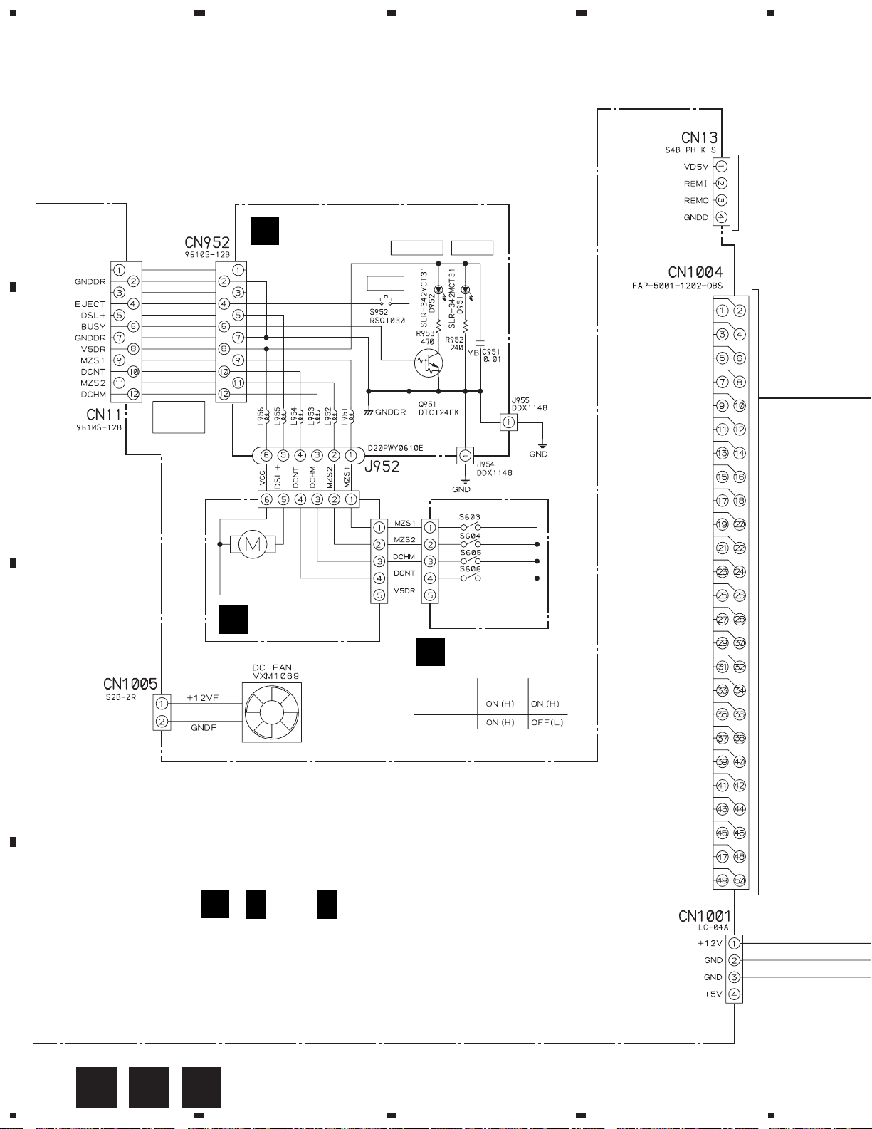
34
Page 35

6. ADJUSTMENT
6.1 PREPARATIONS
6.1.1 JIGS AND MEASURING INSTRUMENTS
DRM-6NX
CD TEST DISC
(YEDS-7 or STD-903)
Low-frequency
oscillator
Precise
screwdriver
Dual-trace
oscilloscope
(10 : 1 probe)
screwdriver
Service remote
(RU-V101)
6.1.2 NECESSARY ADJUSTMENT POINTS
When Adjustment points
Exchange
1.2.3. = Page 39, 40
MAIN BOARD ASSY
(large)
controller
screwdriver
(small)
Interface
screwdriver
(medium)
External adder
amplifier
Exchange
SERVO MECH ASSY
1.2.3. = Page 39, 40
35
Page 36

DRM-6NX
6.2 ADJUSTMENT
6.2.1 HOW TO START/CANCEL TEST MODE
SERVICE REMOTE CONTROLLER
FUNCTION TABLE OF THE REMOTE CONTROLLER (RU-V101) FOR SERVICE
÷ Test Mode
Shows the function table of the remote controller (RU-V101) for service as follows. When operating the CD-ROM directly,
it is possible to operate as shown below by connecting the wired-remote control to the CD-ROM with the interface.
÷ Schematic Diagram of the Conversion Jig for Remote Control Operation
RU-V101
Interface
1
2
3
3P mini jack
Q1: DTC124ES or UN4212
TEST MODE : ON
Power Switch: ON
10k
2.2k
Q1
FUNCTION SW (S1001)
TERM/ON
1 2 3
ON
TEST MODE/ON
REAR PANEL
(IDSB BOARD ASSY)
V +5V
1
REMI
2
3
GND
4
PH type
connector
(4P)
TEST MODE 1
ID SW (S954)
0
1
7
2
6
3
5
4
SW POSITION: 1 to 7
REAR PANEL
(IDSB BOARD ASSY)
TEST MODE 2
ID SW (S954)
0
1
7
2
6
3
5
4
SW POSITION: 0 only
REAR PANEL
(IDSB BOARD ASSY)
CN13
1
CN13
1: VD5V
2: REMI
3: REMO
4: GNDD
4
MAIN BOARD ASSY
Power Switch: OFF
36
Page 37

RU-V101
DRM-6NX
REJECT : Spindle Stop
REJECT : Spindle stop
PAUSE : Pause
PLAY : Play (Trace)
STILL/STEP E :
STILL/STEP e :
MULTI-SPEED + :
MULTI-SPEED – :
CLEAR : Clear
FRAME : Frame set
TIME : Time set
CHAPTER : Track set
SEARCH : Search
10 key : Numerical input
DISPLAY (FUNC + 1) : No entry
STILL (FUNC + 2) : No entry
C-MODE (FUNC + 3) : No entry
VIDEO (FUNC + 4) : No entry
STOP. M (FUNC + 5) : Stop Marker
START (FUNC + 6) : Start
AUDIO (FUNC + 7) : No entry
SPEED (FUNC + 8) : No entry
OPEN (FUNC + 9) : Disc Return
[1] – [6] + CHAPTER : Disc Select
[0] + FRAME : Index Set
Test command
Test command
¶ Test Command
Key Operation Command Description
[0] + [TIME] {0TM} All servo OFF
[2] + [TIME] {2TM} Focus ON/OFF
[3] + [TIME] {3TM} Spindle ON (CAV: 500 rpm)
[4] + [TIME] {4TM} Tracking ON/OFF
[6] + [TIME] {6TM} Focus Up/Down
[8] + [TIME] {8TM} Spindle rotation control: CLV control (single speed)
[9] + [TIME] {9TM} Spindle rotation control : Pseudo CLV control (24 x speed)
[STILL/STEP >>] {SF} 1 Track jump : FWD
[STILL/STEP <<] {SR} 1 Track jump : REV
[
∗
] + [∗] + [∗] + [MULTI-SPEED +] {
[
∗
] + [∗] + [∗] + [MULTI-SPEED –] {
∗∗∗
∗∗∗
MF}
MR}
∗∗∗
Track jump : FWD
∗∗∗
Track jump : REV
37
Page 38

DRM-6NX
6.2.2 ADJUSTMENT LOCATIONS
MAIN BOARD ASSY
TE
FE
SIDE B
VC
VREF
VB
VA
GND
38
SIFB BOARD ASSY
SIDE A
VR952: RF LEVEL ADJ.
VR952
Page 39

CD-ROM Player
1. Focus Offset Check
Focus Error Offset
and
Tracking Error Offset
Auto Adjustment
2. Tracking Error Barance Check
Oscilloscope
DC Mode
V: 1 V/div
H: 10 mSec/div
GND
Prove(10:1)
MAIN BOARD ASSY
FE
GND
START
GND
Prove(10:1)
VREF
VREF
GND
FCS.ERR
GND
(CH1)
(CH2)
A
B
Check
Oscilloscope
DC Mode
V: 500 mV/div
H: 5 mSec/div
GND
Prove(10:1)
PLAY
R=35mm
TEST DISC
PLAY
TEST DISC
Test mode 1
SPDL servo = CLOSE
FOCUS servo = CLOSE
TRKG servo = OPEN
PLAY MODE
6.2.3 CHECK AND ADJUSTMENT
A=B
VREF
A
B
A≠B
VREF
A
C
B
START
TE
VREF
MAIN BOARD ASSY
CD-ROM Player
When there is a DC
component
When there is no DC
component
6.2 ADJUSTMENT
DRM-6NX
39
Page 40

DRM-6NX
3. RF Level Adjustment
¶ Test mode 2
In test mode 2, the disc is started
automatically, single speed CLV (60
min) search is performed, and then
the unit goes into PAUSE status.
TEST DISC
(AUTO PLAY MODE)
AUTO PLAY (CLV) /
PAUSE
VR952
SIFB BOARD ASSY
CD-ROM Player
6.2 ADJUSTMENT
330 mVP-P
±30 mV
START
MAIN BOARD ASSY
VAVREFGND VB VC
+
–
+
–
+
–
VC
VB
VA
External Adder Amplifier
10p
4.7k
4.7k
4.7k
4.7k
4.7k
–
+
+
–
–5V
+5V
75
0.1µ
0.1µ
+
47/16
47/16
+
Oscilloscope
AC Mode
V: 100 mV/div
H: 10 mSec/div
Prove(10:1)
GND
40
Page 41

6.3 FUNCTION OF PERSONAL COMPUTER FOR SERVICING
Direct Commands
〉 TA3SEPL
[Esc] to exit
Use the floppy disc furnished with the product.
DRM-6NX
6.3.1 PROGRAM INSTALLATION AND
REMOVAL
Multi-play control (MPC) has one program to make it resident in
memory and another program that removes it from memory.
(1) MPC. COM : Multi-play control program
(2) MPCRMV. COM : Removes MPC from memory
MPC is executed as follows:
MPC [Enter]
This entry places MPC in memory. Execution of the next
program removes MPC from memory.
MPCRMV [Enter]
6.3.2 CALLING THE MPC WINDOW
When MPC has been placed in memory and your PC is in the key
input wait state..........
Press the GRPH key and the hyphen key at the same to make the
MPC window pop up.
Multi Play Controler for DR-UA124X Ver 0.5
DISC:
Disc Play Pause
ESC key : Closes MPC window
[=] [+] [ ± ] [ ≠ ] key : Select functions
Space key or enter key : Executes selected function
TRACK: TIME:
Volume Open Command
Track
Fig. 1 MPC Window
[Esc] to exit
PIONEER
6.3.3 CALLING A SUB WINDOW
Execute a [Command] function to make a sub-window pop up, and
then a mnemonic command can be executed. Use the ESC key to
cancel a sub-window.
Fig. 2 Sub-Window
6.3.4 COMMAND LIST
Notes:
¶ The complete status "R" is returned when the execution of each
command is completed.
¶ Park mode : A state in which the disc is cramped.
¶ Home mode : A state in which the disc is released (the disc has
returned to the magazine).
Direct Selection of Disc
When the cursor is at the [Disc] position..........
Directly input a number from 1 to 6 to select the disc.
¶ Command List
Command
Name
ZO MAGAZlNE OUT Enters home mode by ejecting the magazine.
ZS DISC SELECT Enters park mode after removing the specified disc from the magazine and cramping it.
The address (DISC number) is to be specified prior to the command.
Example: 3ZS (to select the third disc from the top of the magazine)
ZR DISC RETURN Returns the disc to the magazine and enters home mode.
R J REJECT Stops the disc rotation and enters park mode.
SA START Starts the disc rotation. When the first track is an audio track, the disc will pause at the beginning
of the track while it will pause at 0 minutes 1 seconds 0 frames in a data track.
PL PLAY Enters play mode and plays the disc.
Automatically stops if the specified command adress is overrun during playback.
Example: TM2000PL (Pause at 20 min. 00 sec. frame.)
PA PAUSE Enters pause mode. stopping at the current point.
SE SEARCH Searches for the specified address and enters pause mode after the search operation.
Example: BK4500SE (to specify a block), TR5SE, 6SE (to specify a track)
ExplanationCommand
41
Page 42

DRM-6NX
Command
Name
SM STOP MARKER Sets a stop marker at the specified address.
Enters pause mode when passing over the stop marker during playback, clearing the marker.
The stop marker is also cleared when the CLEAR or REJECT command is supplied before the
stop marker is reached.
Example: BK200000SMPL (T0 pause at 20 minutes 0 second 0 frame sfter playback)
BK BLOCK Uses the address flag to specify blocks . Subsequently, an address entered is regarded as a
block number (BK + a 6-digit number).
TM TIME Uses the address flag to specify a tirne. Subsequently, an address entered is regarded as a time
code (TM + a 4-digit number).
TR TRACK Uses the address flag to specify a track. Subsequently, an address entered is regarded as a time
track number (TR + a 2-digit number).
IX INDEX Uses the address flag to specify an index. Subsequently, an address entered is regarded as an
index number (IX + a 4-digit number).
CL CLEAR Clears the digit buffer (numerical input) and cancels search mode, auto play mode or the stop
marker. When the buffer is cleared during a search operation, the pickup stops moving for a
pause. Resumes normal operation when the buffer is cleared during an auto play or stop marker
operation.
LO LEAD OUT SYMBOL Sets a point in the lead-out area to an address. To be used when setting the stop marker on
the last track of a disc having 99 tracks.
Example: TR99SELOPL
VL VOLUME Adjusts the audio playback level. 0: minimun, 255: maximum
ExplanationCommand
AD AUDIO CONTROL Select the audio outputs.
CM COMMUNICATION Sets the communication mode . With this model, only mode 3 can be set.
KL KEY LOCK Activates or deactivate the keys on the front panel.
?Z DISC NUMBER Displays a three-digit number which indicates the ordinal of the cramped disc from the top of the
REQUEST magazine. If no disc is cramped, "XXX" is returned.
?B BLOCK NUMBER Returns the block number by a 6-digit number. The current address is returned during playback
REQUEST and the pause target address is returned during pause. "XXXXXX" is returned in park mode and
?T TIME CODE Returns the time code by a 4-digit number. The current address is returned during playback and
REQUEST the pause traget address is returned during pause. "XXXX" is returned in park mode and "0000"
?R TRACK NUMBER Returns the track nurnber by a 2-digit number. The current address is returned during playback
REQUEST and the pause traget address is returned during pause. "XX" is returned in park mode.
?I lNDEX NUMBER Simultaneously returns the track number and the index number by a 4-digit number. The current
REQUEST address is returned during playback and the pause target address is returned during pause.
?A ADDRESS Returns the track number, the index number and the P time by a 10-digit number. The current
REQUEST address is returned during playback and the pause target address is returned during pause.
0: OFF, 1: Lch, 2: Rch, 3: STEREO, 4: OFF, 5: Lch, 6: Rch, 7: STEREO
Example: 3AD
Example: 3CM
0: Activate 1: Deactivate Example: IKL
"000000 " is returned in the lead-in area.
is returned in the lead-in area.
"00" is returned in the lead-in area and "AA" is returned in the lead-out area.
"XXXX" is returned in park mode, "0000" is returned in the lead-in area and "AA01 " is returned
in the lead-out area.
"XXXXXXXXXX" is returned in park mode, "0000000000 " is returned in the lead-in area and
"AA01000000" is returned in the lead-out area.
42
Page 43

DRM-6NX
Command
Name
?Q TOC Returns TOC data. When no track number is specified, the first track number, the last track
?G CATALOG CODE Returns the catalog code of the disc being played by a 13-digit number. If no catalog code is found
?O ISRC CODE Returns the ISRC code by a 14-digit number when ISRC code is written.
?P PLAYER ACTIVE Returns operation mode by three characters.
?K DISC STATUS Returns the attribute of the playback disc in 8 characters (Nl - N8).
Command
INFORMATION number and the absolute time of the beginning of the lead-out area are returned by a 10-digit
number.
Example: 0109665544 01: Ist track number
09: Last track number
665544: The lead-out area begins at 66 minutes 55 seconds 44 blocks.
When a track number is specified, the absolute time of the beginning of the track and the code
to indicate whether the track is an audio track or a data track are returned by an 8-digit number.
Example: 10020000 100200: Track 5 begins at 10 minutes 02 seconds 00 blocks.
00: Track 5 is an audio track. (04 = data)
REQUEST or in home mode, thirteen Xs are returned.
REQUEST
MODE REQUEST P00: home mode (without magazine) P02: Setup mode P23: Eject mode
P20: home mode (with magazine) P03: Reject mode P08: Scan mode
P01: Park mode P07: Search mode
P04: Play mode P21: Disc select mode
P06: Pause mode P22: Disc return mode
REQUEST Nl: Disc loading 0: no 1: yes
N2: Audio track 0: none 1: available X: unknown
N3: Data track 0: none 1: available X: unknown
N4: CDV 0: no 1: yes X: unknown
N5: CD-I 0: no 1: yes X: unknown
N6 - N8: (reserved)
Example: 11000XXX
Explanation
?X CDP MODEL NAME Returns the model narne of the CD player. "P155001"
REQUEST
?M COMMUNICATION Returns communication mode " 3 " with this model.
MODE REQUEST
6.3.5 ERROR MESSAGES
Command
Name
E00 COMMUNICATION ERROR Cornmunication line error
¶ Framing error
¶ Buffer overflow
E04 FEATURE NOT AVAILABLE An unusable command has been executed.
¶ Different command mnemonics or mode
E06 MISSlNG ARGUMENT Required parameter has not been specified.
E11 DISC OR MAGAZINE NOT EXIST No disc or no nagazine has not been installed.No disc can be detected.
E12 ADDRESS SEARCH ERROR No search address has not been found.
E13 FOCUS SERVO FAILURE Focus error and failure also on retry.
E14 TRACKING SERVO FAILURE Tracking error and failure also on retry.
E15 FRAME SYNC TIME-OUT PLL frame sync time-out.
ExplanationCommand
43
Page 44

DRM-6NX
Command
Name
E16 INPUT OTHER DEVICE The eject key had been depressed before the command execution was completed.
E90 DISC SELECT FAILURE Tray/disc selection time-out.
E91 CAN'T EJECT MAGAZlNE The magazine cannot be extruded.
E92 ELEVEATION FAILURE Elevation time-out.
E96 START UP FAILURE Unsuccessful start.
E99 PANlC An unrecoverable error or an error with an unknown cause has occurred during drive
Command
operation.
¶ The playback operation cannot be continued and stops.
Explanation
6.3.6 CD-ROM STATUS CHART
P21 P00
P23
LOAD
P21
MAGAZINE
(existence)
HOME
P22
MAGAZINE
(none)
SELECTOR UP
MAGAZINE EJECT
P06
PAUSE
RETURN
P01
PARK STOP
P02
SET UP
P02
TOC
P07
SEARCH
PLAY
SCAN
P08
(RESET)
P03
P04
44
Mode to return "R" when the command arrives
Normal chart (normal transition)
At reset
Brake by C/R, etc.
Page 45

7. GENERAL INFORMATION
DRM-6NX
7.1 IC
7 PD6287B: (IC702: MAIN BOARD ASSY)
¶ Flash Memory
¶ Pin Assignment (Top View)
39
6
5
A
12
A13A14A15A16BYTE
38
37
36
7
8
9
4
3
A
2
A
A
¶ Block Diagram
WE
RESET
44
43
N.C. 1
RY/BY 2
A8A9A10A11A
42
41
40
4
5
7
6
A
N.C. 3
A
¶ The information shown in the list is basic information and may
not correspond exactly to that shown in the schematic diagrams.
1
/A-
15
Vss
DQ
DQ7DQ14DQ6DQ13DQ5DQ12DQ4Vcc
35
34
33
32
31
30
29
28
27
26
25
24
2322
10
11
1
0
A
A
CS 12
Vss 13
OE 14
15
0
DQ
16
8
DQ
17
1
DQ
18
19
9
2
DQ
DQ
DQ0 – DQ
15 – 22, 24 – 31
20
10
DQ
21
3
11
DQ
DQ
15
RY/BY
WE
BYTE
RESET
CS
OE
A
0 – A16
A-
2
12 44 33 43
1414 3 – 11, 34 – 42
1
RY/BY
Buffer
Control
Circuit
Low Vcc Det.
Circuit
Write Circuit
Write/Erace
Pulse Timer
Erace
Circuit
STB
Vcc
Vss
Chip Enable
Output Enable
Circuit
Y Decoder
X Decoder
Address Latch
Input/Output
Buffer
STB
Data Latch
Y Gate
2,097,152
bits
Cell Matrix
45
Page 46

DRM-6NX
6
7
5
Disconnect the
connector.
IDE/SCSI BOARD ASSY
HARD DISK
UNIT
× 2
7
8
× 2
7.2 DIAGNOSIS
7.2.1 DIAGNOSIS METHOD FOR MULTI MECHA ASSY AND HDD
This unit is equipped with an external SCSI terminal. Accordingly, when the SCSI cable is
disconnected from the AXIS NETWORK BOARD Assy, the external SCSI terminal is connected
to the SCSI controller of the PC A/T, and the terminator setting is changed, the built-in HDD and
the MULTI MECHA Assy can be operated from the PC A/T as SCSI devices, and analysis is
possible.
SCSI Cable
Disconnect the
SCSI connector
FUNCTION SW (S1001)
TERMINATOR:
(IDSB BOARD ASSY)
1 2 3
ON
OFF
REAR PANEL
PC/AT
7.2.2 DISASSEMBLY
Removal of the AXIS Network Board Assy and
Hard Disk Unit
1 Remove the Bonnet.
2
Disconnect the
connectors.
3
4
3
× 2
AXIS NETWORK
BOARD ASSY
HARD DISK UNIT
(SLAVE)
MASTER
IDE/SCSI BOARD ASSY
CN4
JP5
JP11
TERMINATOR:
OFF = ON
JP11 (Closed) = (Open)
46
3
AXIS NETWORK
BOARD ASSY
Page 47

Removal of the Power Supply Assy
9
Power Supply
Assy
DRM-6NX
6
5
2
1
× 4
4
3
Rear Side
7
8
CN1
Power Supply
Assy
8
CN2
47
Page 48

DRM-6NX
7.2.3 TROUBLESHOOTING
This section provides useful information to help you
resolve any difficulty you might have with your DRM-
6NX, namely:
÷ The front panel indicators
÷ Errors when accessing the DRM-6NX
÷ Problems running CD-ROM software
÷ Difficulties locating the DRM-6NX in NetWare
÷ Problems locating the domain controller in SMB
÷ Problems when accessing disc changers
÷ Restoring the factory default settings
The Front Panel Indicators
The front panel indicators show the status of the DRM6NX. The indicators have the following functions:
÷ Status - Flashes during startup. When the DRM-6NX
is ready for use, the light goes out. The LED remains
off, unless an error condition occurs.
÷ HDD - Flashes to indicate hard disk activity and SCSI
activity.
Caution!
Never turn off the power when the hard disk
drive is active (while HDD indicator is flashing).
÷ Network - Flashes to indicate the presence of network
traffic.
÷ CHANGER - Light when data is read from the internal
changer and when the SCSI bus is accessed.
÷ Power - Indicates that power is connected to the
DRM-6NX. This LED should remain lit and is only
used to indicate power is present in the DRM-6NX
unit.
Error Conditions
This table shows the front panel indicators under various
error conditions:
Event
CD-ROM has incorrect format
or SCSI bus not connected**
Faulty network connection OFF OFF
Illegal serial no. Flash Flash Flash
Flash load failed Flash OFF OFF
Token-Ring loopback failure
Token-Ring speed error ON OFF Flash
Error in EEPROM Flash OFF OFF
Error in FLASH PROM Flash OFF Flash
Error in SRAM Flash Flash OFF
Error in DRAM/DIMM Flash OFF OFF
Error in DRAM/DIMM
configuration error
Software/Hardware
combination error
Disconnect/reselect drive
error ****
* The Network LED will flash when there is network traffic.
** Check the logfile.txt file in the System folder for more information.
*** The HDD LED and Network LED will flash alternately in this condition.
**** Disable the function by setting the Disconnect/Reselect parameter to
off.
Status LED HDD LED Network LED
OFF Flash Flash*
Flash Flash OFF
Flash Flash OFF
Flash Flash*** Flash***
Flash
Status Indicator On
If the Status indicator remains lit after startup, this may
indicate an error. Most likely there is a problem with the
SCSI bus or with any of the connected disc drives. Make
sure all connected drives have unique SCSI addresses
and that only the last drive in the SCSI chain is terminated.
÷ If some drive error occurs during caching/reading,
caching/reading is canceled and the drive and discs
become disable.
Only restarting this product can clear this condition.
Normal Conditions
The Power LED is controlled by hardware and is always
lit when power is connected.
This table shows the other front panel indicators under
normal conditions:
Event
Initial power to unit ON ON ON
During power-up/Self-test.
Approx. 30 seconds.
After power-up/Self-test OFF ON Flash*
First disc inserted OFF ON Flash*
Last disc removed OFF OFF Flash*
Network Packet arrived OFF N/A Flash*
Flash loading
* The Network LED will flash when there is network traffic.
48
Status LED HDD LED Network LED
Flash OFF OFF
1 Flash/sec 1 Flash/sec 1 Flash/sec
Errors when Accessing the Network
Cache Changer or Inserted Discs
If you get error messages when trying to access the
DRM-6NX or an inserted disc:
÷ Using TCP/IP, make sure that you have assigned a
unique Internet address to the DRM-6NX.
÷ Check the SCSI chain and ensure that all external disc
drives are switched on and that only the last unit is
terminated.
÷ Using Microsoft Windows Network, verify that you
have enabled the SMB protocol.
÷ Consult the error table in section “Error Conditions”
to see if the front panel indicators can help you
identify the problem.
Page 49

DRM-6NX
Problems Running CD-ROM Software
If you have inserted a CD-ROM successfully, but the
software on it refuses to run or produces error messages,
the software may expect the CD-ROM data to be at root
level. In NetWare as well as in the Microsoft and IBM
network operating system environments, you then
need to assign a drive letter to that particular CD-ROM.
In NetWare, the Show All Volumes parameter must be
enabled. See also “Accessing the Network Cache
Changer Resources”.
Some CD-ROMs, e.g the single user version of
“Computer Select”, requires the MSCDEX (Microsoft)
driver. The volume is usually released in a network
version as well. An MSCDEX emulation, called
PIONEERCDEX, is available on the Axis web site. The
PIONEERCDEX makes a CD-ROM on the DRM-6NX
look as if it was locally connected to the PC.
PIONEERCDEX supports Windows for Workgroups.
An MSCDEX emulation for Windows 95 is also available.
If the CD-ROM is a single user version, you must restrict
the number of simultaneous users to one.
Some applications look for information on the CD-ROM
using its default name - if you have set an alias name it
may not recognize the disc and fail to run.
Difficulties Locating the Network Cache
Changer in NetWare
Frame Types - Ethernet
There are basically two different frame types on Ethernet
networks, Ethernet II or IEEE 802.3. The IEEE 802.3
frame can be encapsulated in an IEEE 802.2 LLC frame
or a SNAP frame. All four frame types are enabled by
default with the value
6NX automatically adapts to the frame type used on the
network. This will meet most requirements. Frame
types that are not in use in your network will not be used
by the DRM-6NX.
However, depending on your network, you may want
the DRM-6NX not to operate on some frame types. If
your network has multiple sections with different frame
types on some of the sections, then the DRM-6NX
might log on to the wrong network section and adapt to
a frame type incompatible with the intended network
section. For this reason, you have the option to disable
those frame types by changing the parameter from
to
off
.
auto
, which means that your DRM-
auto
Alternatively, it is possible to use the eight digit network
number appropriate to your segment of the network, in
the form xx-xx-xx-xx (e.g. 00-3F-B5-01). In all normal
cases this will not be necessary since autodetection will
handle most cases. However, this has to be done by
directly editing the
config.txt
file using a text editor.
Although you cannot enter the network number from a
Web browser, you can display the frame type and
change the value to
auto
or
off
, if required.
Problems Locating the Domain Controller
in Windows (SMB)
If there is a problem locating the primary domain
controller when using user-level security mode in
Windows (SMB), all users will be denied access to the
DRM-6NX.
Web Browser
You can verify the configuration settings from the DRM6NX web interface. Within the Administration pages,
click Network Settings, Detailed View, and open the
Windows (SMB) tab to do that.
Local Administrator Account
In Windows NT, you can correct the problem by logging
on to the DRM-6NX as local administrator. Note that the
local administrator is not the same as an Administrator
with an account on the domain.
In the Map Network Drive dialog, specify the following:
Path: The DRM-6NX name
Connect as: Server name\Administrator
Password: The password set in the
Example:
The host name of the DRM-6NX is cdserv.
Path:
Connect as:
NOTE:
7 In Windows 95, you cannot tell the SMB client to change domain and user
when you are already logged in. Therefore, you cannot use the local
administrator account to solve domain problems in the Windows 95
environment.
ServerPassword parameter
\\cdserv\root
cdserv\Administrator
49
Page 50

DRM-6NX
Problems When Accessing Disc Changers
Disc changer flutter can occur if a user requests access
to a CD-ROM when another user is already reading data
from another CD-ROM. The changer may then attempt
to service both requests by repeatedly changing
between the two CD-ROMs and transferring a small
amount of data each time. Because of the relatively long
time needed to change CD-ROMs, the data transfer
rate to both users will become unacceptably low.
The JukeBox Lock Time parameter in the DRM-6NX
configuration file specifies how long a user has exclusive
access to a CD-ROM during a data read operation. This
is to prevent disc change flutter in order to optimize
access speed when many users are accessing different
discs in the same changer.
The JukeBox Lock Time parameter will ensure that
when there are simultaneous requests for access to
different discs, a sizable block of data is transferred to
each user before the access is changed.
÷ If the JukeBox Lock Time parameter is set too low,
the data transfer rate will be unacceptably low.
÷ If the JukeBox Lock Time parameter is set too high,
the disc drive will time-out on a second user’s request
before the first user’s access is completed. This will
result in users receiving a ‘CD-ROM not available’
notice.
The default setting is 0 seconds which disables this
function.
NOTE:
7 If some drive error occurs during caching/reading,Caching/Reading is
canceled and the drive and discs become disable.
Only restarting this product cam clear this condition.
Web Browser
To restore the defaults settings using a Web browser:
1. Start the Web browser.
2. Click Administration.
3. Click PIONEER Changer.
4. Click Factory Defaults.
The factory default setting will now be restored and the
DRM-6NX will then automatically restart.
FTP
To restore the default settings using FTP:
1. Log in to the DRM-6NX with the command:
ftp <host name>
, where
<host name>
is the name assigned
in your system host table.
2. You will be prompted for user id and password. Use
the user id
(
root
is the user id with the highest priority).
root
, which has the default password
pass
3. Restore the default setting with the command:
get defaults
The unit will then automatically restart.
4. Log out using any of the commands
quit, bye
or
exit
depending on your FTP version.
Reset Button
To restore the default settings using the Reset button:
1. Turn off the DRM-6NX.
2. Press and hold the Reset button while you switch on
the DRM-6NX. Keep the Reset button pressed until
the Network indicator flashes at regular two second
intervals.
Restoring Factory Default Settings
If required, you can restore the factory default settings
to your DRM-6NX , e.g. if you have disabled all network
protocols. You can use any of these methods:
÷ Web browser
÷ FTP on a TCP/IP network
÷ Reset button
Step by step instructions for each method are given
below.
NOTES:
7 The node address, the Hardware Address parameter, will remain
unchanged, but all other parameters will be restored. You will thus need
to re-assign the Internet address to re-establish the Web browser
connection.
7 All Cached data in the HDD is cleared when restoring the factory default
setting.
50
Reset button
3. Release the Reset button and wait at least two
seconds (one flash of the Network indicator).
4. Press and hold the Reset button for at least five
seconds until the Network indicator remains
constantly lit.
5. Turn off the DRM-6NX. And switch on the DRM-6NX
again.
The factory default setting will now be restored.
Page 51

Troubleshooting Know-how Collection
DRM-6NX
Details of Error
Q1. The Status LED continues to flash (5 minutes
or more) and never stops.
Q2. How can I reset to the factory default settings?
Q3. The firmware version can not be upgraded.
Measure
A1. Check that the SCSI Termination switch on the rear
of the DRM-6NX is ON. If this does not help, reset to
the factory default settings.
A2. Resetting to the factory default settings can be done
as described below.
1. Hold the Reset button pressed while switching
the power to the DRM-6NX ON, and keep it
pressed until all three LEDs flash at the same
time. At this time, release the Reset button once,
and press it again after waiting for about 5 sec.
When the Status LED and the Network LED have
lit and gone out, switch off the power to the DRM6NX and then restart it.
2. Connect with a web browser, enter Administration,
and press the Factory Default button.
3. Log in at the DOS prompt with ftp 192.36.253.80
(IP address). (The User Name is root and the
Password is pass.) Enter "get defaults" to obtain
the Factory Default settings.
A3. Enter FLASH in capital letters When you issue "put"
command at ftp command line.
Q4. Connection is possible with ping and ftp, but
opening with a Web Browser is not possible.
Q5. Ping passes, but connection by ftp or web
browser is not possible.
Q6. Changing of the IP address is not possible with
arp and ping Command.
Q7. The network computer does not see the DRM-
6NX.
A4. Has the Status LED stopped flashing? The DRM-6NX
is ready when the Status LED has stopped flashing.
If the LED has not stopped flashing, wait for about 5
minutes. If it still does not stop flashing, refer to Q1.
A5. Restart the DRM-6NX once and start again from IP
address setting. Changing of the IP address with arp
and ping command is possible only within 30 minutes
after start of the DRM-6NX.
A6. Changing of the IP address with arp and ping command
is possible only within 30 minutes after start of the
DRM-6NX. Restart the DRM-6NX once and start
again from IP address setting.
A7. In the default settings The DRM-6NX can be seen
only when the workgroup of the client PC is
"workgroup". Even when it is "workgroup", it can not
be seen for some time after start. Even when it can
not be seen, the search function in the start menu of
the computer can be used to search for it. In the
default settings. The computer name of the DRM6NX is pioneer ****** (****** stands for the last six
digits of the serial number).
Q8. At the time of access by a network computer,
a password is demanded immediately, but
access is not possible, no matter what is
entered.
A8. This condition can occur when resetting to the factory
default settings has not been done after a change of
the firmware. Reset once to the factory default
settings. Refer to Q2.
51
Page 52

DRM-6NX
Details of Error
Q9. The network computer does not see the DRM-
6NX. The DRM-6NX also is not found by
computer search.
Q10. A volume which could be seen until now
suddenly has disappeared. (Access to the
server is possible.)
Q11. The settings for network and SCSI do not
become effective.
Measure
A9. This condition can occur when resetting to the factory
default settings has not been done after a change
of the firmware. Reset once to the factory default
settings. Refer to Q2.
A10. a. It is possible that the volume has been unmounted
because a hardware error has occurred for the
changer during operation. Please check the event
log. In such a case, a volume-cached volume
should be visible. For recovery, restart the DRM6NX.
b. If this occurred during caching, it is possible that an
HDD error has occurred during operation. Please
check the event log. If it looks like a write error to
the HDD has occurred, it is to be feared that the
HDD has been damaged physically. If the same
condition occurs with caching after a restart, use
the Format button to format. However, all cached
data will be lost by formatting.
A11. In principle, the network and SCSI settings become
effective after restart of the DRM-6NX and the
connected DRM-6324X.
Q12. The cache setting does not become effective.
Q13. Network connection is not possible at all. Even
ping is not effective.
Q14. The access right can not be changed with
Windows Sharing in File Rights.
Q15. Web Security setting in regard to the System
directory is not possible with File Rights.
A12. The cache setting (Normal/Mirror/Persistent)
becomes effective from the magazine inserted after
the change.
A13. Check that the link LED of the hub is lit. Depending
on the hub, the link LED may not light. In such a case,
disconnect and reconnect the network cable until the
link LED lights.
A14. Independent of whether the access right is set to Full
or to Read Only, the access right in regard to the
volume does not change. It is always Read Only.
A15. The setting is disregarded, as access from the web
is possible only to the Volume directory, while access
to the Root or the System directory is not possible.
52
Page 53

7.2.4 UPGRADING THE NETWORK CACHE CHANGER
DRM-6NX
This section includes the following information:
÷ Obtaining new software
÷ Upgrading the PIONEER Network Cache Changer
DRM-6NX
Obtaining New Software
The following software for the DRM-6NX can be updated
free of charge:
÷ The DRM-6NX software held in Flash Memory
Over the Internet
You may wish to check the PIONEER’s WWW Home Page
http://wwwbsc.pioneer.co.jp/is/products/index.html
where you can download the latest versions of the
software.
A link to the Products web site is available on the DRM6NX’s Home Page.
NOTE:
7 If you cannot access to the Products web site, you may access to other
PIONEER Group’s web site.
United States http://www.pioneerusa.com/
Europe http://www.pioneer-eur.com/
product.htm
Flash Memory
The software that runs on your DRM-6NX is stored
in Flash Memory. This is a memory chip that, like
ordinary ROM memory, keeps its contents even
when the power is turned off. What makes it
unique is the possibility to erase its contents and
write new data to it. This means that when software
updates are available for your DRM-6NX, you can
make use of them without having to replace any
parts. The new software is simply loaded into the
DRM-6NX over the network.
Your Dealer
Contact your dealer to check if there has been any new
issues of the software. You should have your present
version numbers ready to compare against the latest
software issues from PIONEER.
Upgrading the Networ Cache Canger
The DRM-6NX software can easily be upgraded over
the network using FTP on a TCP/IP network.
To upgrade over the network you will need the following:
÷ The file with the new DRM-6NX software. The name
of this file is of the form
for the software release 5.00 for the Ethernet version
of the DRM-6NX.
÷ A computer on the network with TCP/IP and FTP.
÷ The DRM-6NX must also be installed on the network
with TCP/IP as described in “Assigning an Internet
Address”.
Follow these steps to upgrade the DRM-6NX:
1. Log in to the DRM-6NX with the command:
ftp <host name>
where
Internet address of your DRM-6NX.
2. You will be prompted for user id and password. Use
the user id
root
, which has the default password
3. Issue the command
mode.
4. Issue the command
<software name>
cde_500.bin
NOTE:
7 If you intend to download an earlier version or a beta version, you need
to type FLASH in capitals, i.e. put <software name> FLASH, to force
a flash memory load.
is the name of the new software, e.g.
.
5. Wait for the flash memory load to finish. This normally
takes 1 to 4 minutes. The unit will then automatically
restart with the new DRM-6NX software.
6. Log out using the command quit, bye or exit depending
on your FTP version.
7. After upgrading new firmware, you have to restore
the factory default setting.
Caution!
Be careful not to interrupt the file transfer. If the
transfer is interrupted the DRM-6NX may have to
be re-initialized by your dealer.
product_version.bin
<host name>
bin
to change to binary transfer
put <software name> flash
, e.g.
cde_500.bin
is the name or
where
pass
.
Instructions on how to carry out the update are also
supplied with the new software.
53
Page 54

DRM-6NX
Upgrading the Internal Drives
The internal disc drives can be upgraded via the DRM6NX web interface.
Follow these steps to upgrade an internal drive:
1. Make sure you have the new software available on
the network.
2. Start the Web browser.
3. In the location/address field, enter the name or
Internet address of your DRM-6NX.
4. Click Administration.
5. Click This DRM-6NX.
6. Click on the icon that represents the device you want
to upgrade.
7. If the firmware upgrade capability is detected for the
selected drive, you can click Upgrade Firmware...
8. Locate the new software file and click OK.
Upgrading using the Parallel Port
You will need:
÷ A PC with at least a 286, 640 kb memory, MS-DOS
3.3 or greater.
÷ DRM-6NX flash loading kit consisting of:
÷ Flash loading cable
÷ Loading software: FSTPRN.EXE
÷ The file containg the new software version
How to upgrade
1. Switch off the power.
2. Remove the bonnet.
3. Disconnect the LAN cable and the SCSI connector
from the AXIS NETWORK BOARD Assy.
4. Connect the parallel cable to the PC LPT1 port and to
the 26-pin array on the AXIS NETWORK BOARD
Assy. Make sure the parallel cable connector is
mounted with the arrow, close to pin 1, facing the
ETRAX chip located in the middle of the PCB.
5. Switch on the power to the DRM-6NX.
6. Copy the flash load software (FSTPRN.EXE) and the
new software file to a common directory.
7. Start the loading sequence with the DOS command
fstprn <binary file> .
It is also possible to load the print server with the
standard DOS copy command:
copy /b <binary file> LPTx (x = LPT port no.)
NOTE:
Do not forget the /b (for binary) switch in the copy
command.
How to monitor the loading procedure
When the loading is started, the network LED will start
flashing with rate of 2 Hz (loading time between 30 sec
and 4 min).
The loader will consider itself completed and the led will
flash with a rate of 0.5 Hz.
In case of error, the flashing rate will be 1 Hz (with the
on period much longer than the off period).
There will also be a message on the PC screen telling
you if the loading was successful or not.
Final steps
If you have made a software update including parameter
changes (e.g. from 1.x to 2.x) a reset to factory defaults
is required.
54
For restoring to the factory default settings, refer to
"Restoring Factory Default Settings" in "Troubleshooting".
Assemble the DRM-6NX and attach all cables.
Page 55

Disconnect the SCSI connector
and LAN cable.
DRM-6NX
AXIS NETWORK
BOARD ASSY
X9 Connector
Upgrading using the Parallel Port
Control Cable
Service Part No.
(GGD1210)
LPT1 Port
PC/AT
55
Page 56

DRM-6NX
7.3 BLOCK DIAGRAM
MULTI MECHA ASSY
(DXB1653)
SERVO MECHANISM
ASSY (DXB1654)
PICKUP
ASSY
(DWY1069)
SPINDLE
MOTOR
(DXM1097)
STEPPING
MOTOR
(DXM1096)
MAIN BOARD ASSY
(DWX1906)
HEAD AMP
IC201
(AN8849SB)
ACTUATOR
DRIVER
IC451
(M56759FP)
SPINDLE
MOTOR
DRIVER
IC501
(AN8480SBB)
STEPPING
MOTOR
DRIVER
IC411
(LB1836M)
DIGITAL
SERVO
PROCESSOR
IC231
(MN662752CDM1)
ACTIVE
TERMINATOR
IC801
(BH9595FP–Y)
1 Mbit
DRAM
IC302
(LC321667CJ–25)
CD-ROM
DECODER
&
SCSI I/F
IC301
(LC895126–LF4L)
SCSI
I/F
LOADING
MOTOR
(VXM1033)
DISC
SELECT
MOTOR
(VXM1033)
VIBRATION
SENSOR
IC951
(BU3892FV)
LOADING
MOTOR
DRIVER
(Q17, Q18)
DISC SELECT
MOTOR
DRIVER
(Q11, Q15)
EEPROM
IC12
(NM93C66EM8)
CPU
IC701
(MB90T553PF)
FLASH
ROM
IC702
(PD6287B)
IDE/SCSI
BOARD
ASSY
(DWX1917)
AXIS
NETWORK
BOARD
ASSY
(DWN1001)
HARD DISK
UNIT
(DXB1696)
CONNECTOR
BOARD ASSY
(DWX1921)
56
Page 57

8. PANEL FACILITIES AND SPECIFICATIONS
8.1 PANEL FACILITIES
Front View
NETWORK indicator
Flashes to indicate the presence of network
traffic.
HDD indicator
Flashes to indicate hard disk activity and SCSI
sctivity.
STATUS indicator
Flashes during startup. When the DRM-6NX is
ready for use, the light goes out. The LED
remains off, unless an error condition occurs.
POWER indicator
Lights up when the power is on.
CHANGER indicator
Lights when data is read from the internal
changer and when the SCSI bus is accessed.
DRM-6NX
POWER button
Press to turn the power on/off.
Caution!
The HDD indicator lamp is flashed during internal
hard disk caching operations. Take care not to turn
off the hard disk at such times.
7 Diagram illustrating installation of power button
cover
Use this cover to prevent
inadvertent power off during
hard disk operation and when
the system is running.
MAGAZINE EJECT button
Press this button when removing the CD-ROM magazine.
NOTE:
The magazine will not eject if the rear panel FUNCTION switch #3 is set to
the UP/ON disabled position.
Magazine insertion slot
A front-loading mechanism that makes replacing the magazine
simple.
57
Page 58

DRM-6NX
Rear View
Ventilators
Openings are provided for
ventilation, to ensure reliable
operation and to protect it from
overheating. These openings must
not be blocked or covered.
SCSI connector
A 50-pin Centronics connector for connecting external
PIONEER CD/DVD-ROM drives (a total of 5 units can be
connected)
NOTE:
÷ Do not connect a CD-ROM or DVD-ROM drive other than a Pioneer
drive to the SCSI terminal on the rear panel.
÷ Do not connect this terminal to a SCSI terminal on a PC as this could
cause malfunction or breakdown.
“SCSI CONNECTION FOR PIONEER CD-ROM/DVD-ROM DRIVE
ONLY. DO NOT CONNECTSCSI CONTROLLER.”
÷ Assign a SCSI ID between 2 to 6 for drives that are connected. SCSI ID
0, 1 and 7 are reserved for the internal CD-ROM changer, hard disk drive
and network board. Thus never assign IDs 0, 1 or 7 to an external drive.
Black cover
The SCSI ID switch of
the internal CD-ROM
changer is inside this
cover. Note that changing this ID setting may
cause a breakdown. Do
not remove this cover.
FUNCTION switches
Used to set the
operation mode of the
internal CD-ROM
changer. Turn the
power off to the unit
before changing the
operating mode.
No. 1: SCSI terminator switch for internal CDROM changer
It is set to ON (terminator ON) at time of shipment.
Set it to OFF (terminator OFF) when other drives are
to be connected to the SCSI terminal and set the
terminator on the connected drive.
No. 2: RESERVE (for service use only)
Must be set to OFF.
No. 3: Disable magazine eject button
ON: Disables MAGAZIN EJECT button (eject disable)
OFF: Enables MAGAZIN EJECT button (eject enabled)
SIGNAL GND
terminal
AC IN socket
Connect to a wall outlet. This unit is designed to operate at AC
110 – 240 V 50/60 Hz. (There is no power supply voltage
swtich because switchover takes place automatically inside
the unit.)
The accessory power cable is for use in North America.
In order regions, please consult your dealer for imformation on
how to purchase a power cable.
Reset button
Press this button to return all settings to their factory defaults.
Network connector
Connect to the Ethernet or Token Ring network (RJ-45
connector, 100 Base-TX/10 Base-T).
58
Page 59

8.2 SPECIFICATIONS
454
439.2
20
212
153
150
Unit: mm
Supported Systems
Novell NetWare
Microsoft Windows Windows for Workgroups,
Microsoft LAN Manager
IBM LAN Server LAN Server 1.3 and above
TCP/IP Supports all UNIX dialects
WWW Internet/Intranet over HTTP 1.0
Supported Protocols
Novell NetWare NCP over IPX, RIP, SAP.
Windows and OS/2 SMB over NetBIOS/NetBEUI
UNIX NFS over UDP/IP, TCP, ARP,
WWW HTTP over TCP/IP
Network Management
SNMP MIB-II and private enterprise MIB. Platform
independent configuration and management from
standard Web browser.
Supported Disc Format
NOTE:
This unit does not support the use of CD-DA Audio Discs.
Physical Format Only 2048 Bytes/Block format is
NetWare 3.11, 3.12, 4.10 and 4.11
Windows 95, 98,
Windows NT v3.51, v4.0
LAN Manager 1.3 and above
through NFS over UDP/IP on
TCP/IP network
and HTML 2.0 compatible
browsers
and SMB over NetBIOS/TCP/IP.
RARP, BOOTP, DHCP, WINS/
NBNS, SNMP, FTP
supported in this system.
Physical formats to be supported
are Mode 1, Mode 2 form 1,
Multi-session, and packet write
(Variable).
DRM-6NX
Performance
Date Throughput <1,300 kbytes/s (100BASE-TX)
<1,050 kbytes/s (10BASE-T)
Hardware Internal Hard Disc Drive
Storage Capacity 5.1 GB
Average seek time 9.5ms
Internal CD-ROM Drive
Data transmission speed
1,800 – 3,600 kbytes/s
Average access time 75ms
Interface
RJ-45 for 100BASE-TX and 10 BASE-T
SCSI connector (SCSI-2 support)
for PIONEER CD/DVD-ROM
drives (Up to 5 drives).
Accessories
6-disc magazines x 2
Power cable x 1
Operating instructions x 1
Power button cover x 1
SCSI connector cover x 1
Internal network board serial
number label x 1
Others
Power requirements AC 110 V – 240 V, 50/60 Hz
(automatic select)
Power consumption AC 110 V – 240V, 0.62 A
Dimensions 212(W) x 454(D) x 153(H) mm
8-11/32(W) x 17-27/32(D) x 6-1/32(H) in.
Weight 6.4 kg (14 lb 2 oz)
Operating temperature
Operating humidity 10 % to 80 %
Storage temperature
+5 to +35 °C (+41 to +95 °F)
–20 to +60 °C (–9 to +140 °F)
Logical Format Logical format to be supported
is basically ISO9660 (include
Rock ridge and Joliet extension).
Software Updates
Flash memory allows central and remote updating of
the Network Chache Changer Software over the
network using FTP over TCP/IP.
NOTE:
Specification and design subject to possible modifications without notice due
to improvements.
59
Page 60

DRM-6NX
Accessories
6-disc magazines x 2
(DXA1864)
Power cable (for U.S.and Canada) x1
(DDG1071)
SCSI connector cover x 1 Power button cover x 1
(FCN-780C050-14)
(DNK3626)
60
 Loading...