

Page 1
Ņŋ ݲሕྕ
DJ MIXER
DJM-250-K
DJM-250-W
http://www.prodjnet.com/support/
ຢ༧ࠝ၃ዹ࿎࢜٢ၳ࿏ȂᄪႩࢌ፯ඝྊᄲܿᄪႩ࠵ႚˈ֔᎓ݓቂྈࢭٛ൰ȃ
The Pioneer website shown above offers FAQs, information on software and various other types of information
and services to allow you to use your product in greater comfort.
ቂངಖ༚
Operating Instructions
֦ௗֻቂ
ቂٛ൰ขኡޚቂངಖ
Page 2
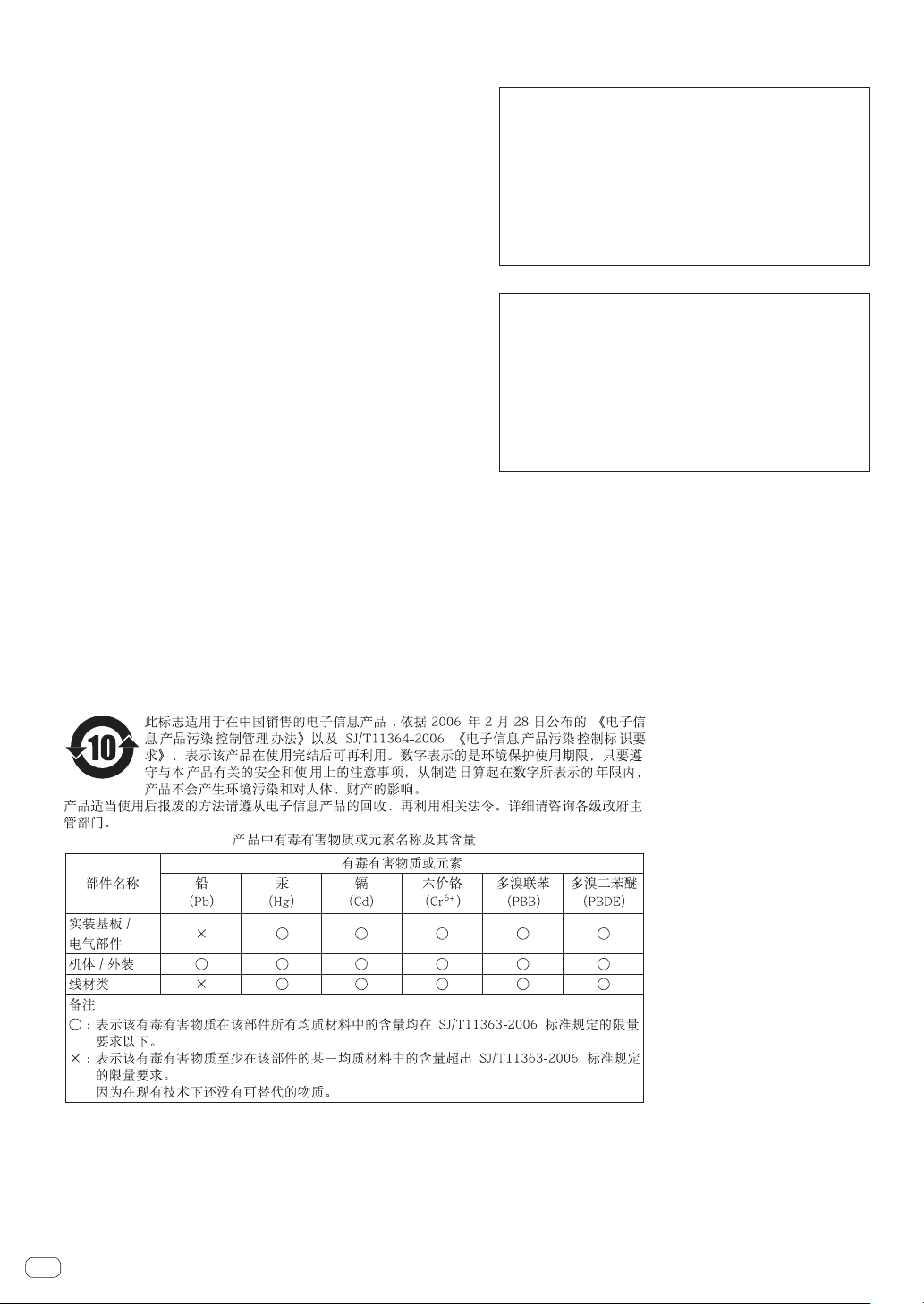
感谢您惠购先锋产品。 请通读使用说明书,了解本型号的正确操作方法。 通读之后,请妥善保存,以备日后参考。
在某些国家或地区,电源插头和插座的外形可能与说明明图存在差别。 但是设备的连接和操作方法相同。
ࡻ
ׁᎧનֻ߷༽ᄹȃၓ߷ፒটኳডۂݢࢽˈข
႙ใᎧᇛ࿒ܿ๒ධ˄൸ডൃ˅
ׁᎧࡒˈডඝ֬௷݉༽ȂࠀȂቩডන
ፇ፩ȃ
D3-4-2-1-3_A3_Zhcn
ࡻ
ݕᇜ۫نݢኑፇˈขᏇႿኡޚᇜངಖȃ
૰ቂݢኑܿݢᅼᇡ࣭য়ডݓฏߑልȃฬ֦ቂׁ
Ꭷݓฏܿݢኑݢᅼ࠲فಅ֊ຢኵܿྈᅍݢᅼ
˄ijĴıġŗডIJijıġŗ˅ȃ
D3-4-2-1-4*_A3_Zhcn
ࡻ
ၓ߷ፒটኳࢽˈข႙ใಖটኑ˄ݞัܿ
ᎋ݃˅ׁᎧຢȃ
D3-4-2-1-7a_A3_Zhcn
Ꮾ
Ꮾܿၫޡޡȣ
ĬĶġɆġፚġĬĴĶġɆ˗ᄆĹĶġˁœʼn˄୩ษଁၝޛ˅
ข႙ׁᎧᎧࠞடܿ٠ྈˈড֬௷ࡴ
ডᆷፊືܿ٠ྈȃ
D3-4-2-1-7c*_A3_Zhcn
ׁ࣮ᎧܿłńنဂቪႪ၆ቂܿłńݢኑنᏰ
࠲ˈዏׁنဂכᅐّຢܿȃׁᎧݢ
ኑღຢłńنဂܿᎧፔቈᅒ૰ጽܿ
ၕᅃเହᄵȃ࣮ިღܿنဂஏܸłńݢኑ
نᏰˈ૰ঐዉڈᆒ፱ܿۂݢ၌ნȃّᄛכᅐቧ
ᇵဢນۃ୲ȃ
٣ৱ˄০ඓ݃˅ቂˈׁᎧכᅐࣰ
۰ුםنᏰճڼ᎐ݢኑنဂହިݢኑȃ
D3-4-2-2-1a_A2_Zhcn
᎙ሃ
ׁᎧܿON/OFF࣋ঐဵภިହᏋłńݢኑن
ᏰܿภؠݢஉȃቈݢኑღޭׁᎧඩ᎐ިධ
ܿᏮቂˈᅍᇋ۰łńݢኑنᏰճڼݢኑღହި
ภؠݢஉȃሓۨˈฬׁ֦ᎧᎧڈߙໍࢽ
ࢮ๒ᇸ۰łńݢኑنᏰճڼݢኑღȃၓமןಁট
ኳࢽˈ٣ৱ˄০ඓ݃˅ቂˈݢኑღ
ᇓሥ۰łńݢኑنᏰճڼȃ
D3-4-2-2-2a*_A3_Zhcn
ݢኑღ᎙ሃჵ
ข༇ڕنဂؠࠍވݢኑღȃճنဂ႙ଲݢኑ
ღˈ෩႙ቂ༇บݢኑღˈሓၓጝᆼ૰ঐܷޥ
௸ডݢদȃ႙ׁᎧȂয়નডඝྊ႘ᅼݢኑღ
ຢˈডᇵඝྊߴৄᅼݢኑღȃ෧႙ݢኑღড
ඝྊܿღ֘ࡔȃݢኑღܿ؝ღሥ߷ፒ־เةຢ
ಅȃݢኑღ།ཿ૰ঐܷটኳˈডዉڈเۂݢȃ
٢৹يݢኑღȃ࣮ߙოݢኑღ།ཿˈขખፚ
ࠝ࢞ཌྷ་ฝၕᅃ፩ᄩডᄁ༌ຟᄵȃ
S002*_A2_Zhcn
Zhcn
2
Page 3

目录
如何阅读本说明书
本说明书中显示、菜单和按钮的名称列在括号内。(例如,
[MASTER] 声道、[ON/OFF]、[File] 菜单)
开始之前
特点 .......................................... 4
系统设置示例 .................................. 4
开箱检查 ...................................... 4
接线
部件名称 ...................................... 5
连接输入/输出端子 ............................ 6
关于 AC 适配器 ................................. 7
操作
控制面板 ...................................... 9
关于本机的电源开关 ............................ 9
基本操作(混音器部分) ........................ 10
使用滤波器功能(滤波器部分) .................. 11
选择交叉渐变器的曲线特征(交叉渐变器部分) ... 11
使用渐变器开始播放先锋 DJ 播放机
(渐变器启动部分) ............................. 11
监听耳机的声音(耳机部分) .................... 12
使用麦克风或外部设备(MIC/AUX 部分) .......... 12
附加信息
故障排除 ..................................... 13
方块图 ....................................... 14
关于商标和注册商标 ........................... 14
规格 ......................................... 14
Zhcn
3
Page 4
开始之前
特点
本机作为一款 DJ 混音器,融合了先锋会所声效世界标准 DJM 系列技术。作为一款标准类型设备,它配备混音所需的
所有基本功能,可轻松驾驭 DJ 表演。
SOUND COLOR FILTER
每个声道均配备了 SOUND COLOR FILTER 功能,只需旋转
较大控制装置即可实现滤波器音效。 这样可以为 DJ 表演
直观地安排和混合曲目。
MIC/AUX 输入
本机配备了三组可输入外部设备(计算机、便携式音频装
置、电视机、合成器等)音频信号的 AUX 输入端以及一个
麦克风输入端。 它不仅可用于 DJ 表演,还可用作前置放
大器来欣赏音乐。
3 波段均衡器
本机配备 3 波段均衡器,可单独调节高、中、低频率范围的
音量。不但可以根据自己的喜好调节音调,还可按逆时针
方向旋转控制旋钮,完全去除某一范围的声音(隔音器)。
XLR OUTPUT
本机配备了音频信号质量损失较少的 XLR 平衡输出端,以
较高音质进行 DJ 表演。 此外,也可在不更改端子的情况
下将其连接到有源扬声器或支持 XLR 输入端的其它设备。
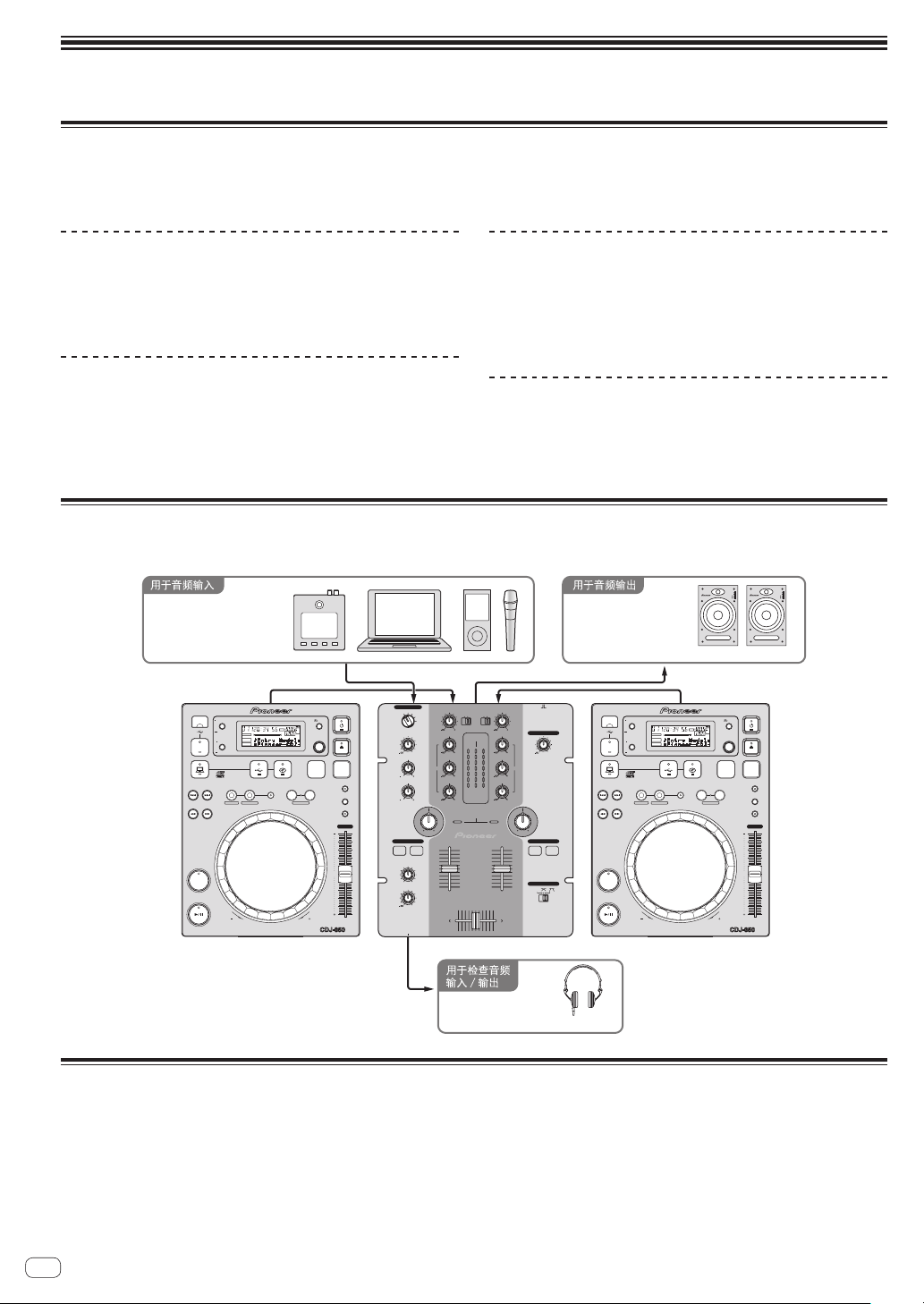
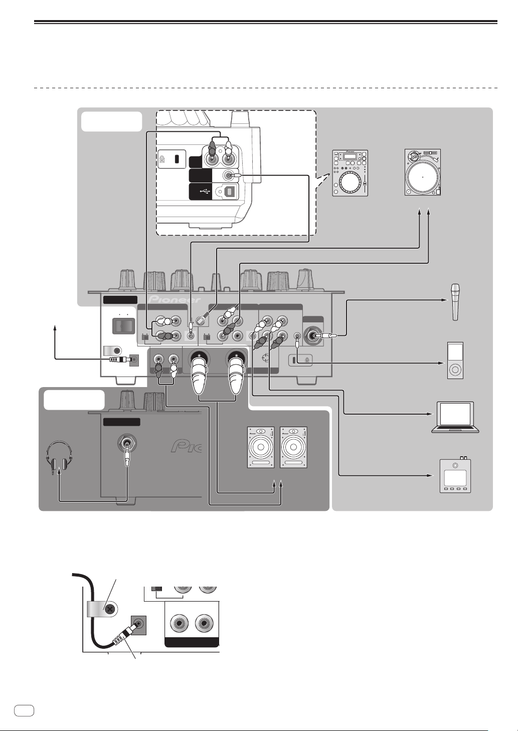
系统设置示例
组合本机和 DJ 播放机及外设设备,就可实现如下图所示的 DJ 系统。
ڈධ
ݢ
צᄔሕ൮ົֻ
ఴࠞ
MIC/AUX
OFF
TRIM
TRIM
PHONO
PHONO
CD
CD
/LINE
/LINE
9
HI
HI
MASTER
CH-1 CH-2
OVER
OVER
9
+4
+4
MID
MID
+2
+2
0
0
EQ EQ
-
6
-
6
9
-
12
-
12
LOW
LOW
-
18
-
18
dB
dB
LEVEL
9
SOUND COLOR FILTER
CH-1 CH-2
9
9
9
9
2 CHANNEL DJ MIXER
DJM-250
MASTER LEVEL
FADER START
CH-1 CH-2
CROSS FADER
THRU
DJM-250
USB
STOP
TRACK SEARCH
SEARCH
CUE
PLAY/PAUSE
TIME MODE
AUTO CUE
DISPLAY
UTILITY
SOURCE SELECT
FTEMPO %
REMAIN
MS
LOCK
A.CUE
INFO
BROWSE
MP3/AAC
WAV/AIFF
IN/CUE OUT
REVFWD
BEAT LOOP
RELOOP/EXIT
LOOP
OUT ADJUSTHOT LOOP
LOOP DRIVE
16
BPM
PLAYLIST
CDJ-350
SELECT PUSH
MIC
AUX 1
BACK
DISC
BPM
LOCK
VINYL MODE
TEMPO RANGE
MASTER TEMPO
TEMPO
0
MULTI PLAYER
AUX 2
AUX 3
LEVEL
0
HI
1212
LOW
1212
LPFHPF LPFHPF
HEADPHONES
CH-1 CH-2
MIXING
MASTERCUE
LEVEL
0
PHONES
݃
ኑᆲ໌ධȂᏠȂ
ܐධ݃
ONOFF
0
TRACK SEARCH
PLAY/PAUSE
TIME MODE
AUTO CUE
DISPLAY
USB
STOP
UTILITY
SOURCE SELECT
MP3/AAC
WAV/AIFF
IN/CUE OUT
SEARCH
CUE
F TEMPO %
REMAIN
MS
16
LOCK
A.CUE
BPM
INFO
BROWSE
BEAT LOOP
RELOOP/EXIT
LOOP
OUT ADJUSTHOT LOOP
LOOP DRIVE
REVFWD
INPUT
1
2
34EQ
POWER
S-DJ05
BACK
SELECT PUSH
PLAYLIST
VINYL MODE
TEMPO RANGE
MASTER TEMPO
MULTI PLAYER
CDJ-350
INPUT
1
2
34EQ
POWER
݃
DISC
BPM
LOCK
TEMPO
0
݃
开箱检查
! AC 适配器
! 电源插头
! 使用说明书(即本说明书)
Zhcn
4
ߓ
HDJ-500
݃
Page 5
接线
执行或更改设备之间的连接时,请务必关闭电源并从电源插座拔下 AC 适配器插头。
连接 AC 适配器之前,等待直至设备之间的所有连接完成。
仅使用本机随附的 AC 适配器。
有关需要连接的部件,请参阅操作说明书。
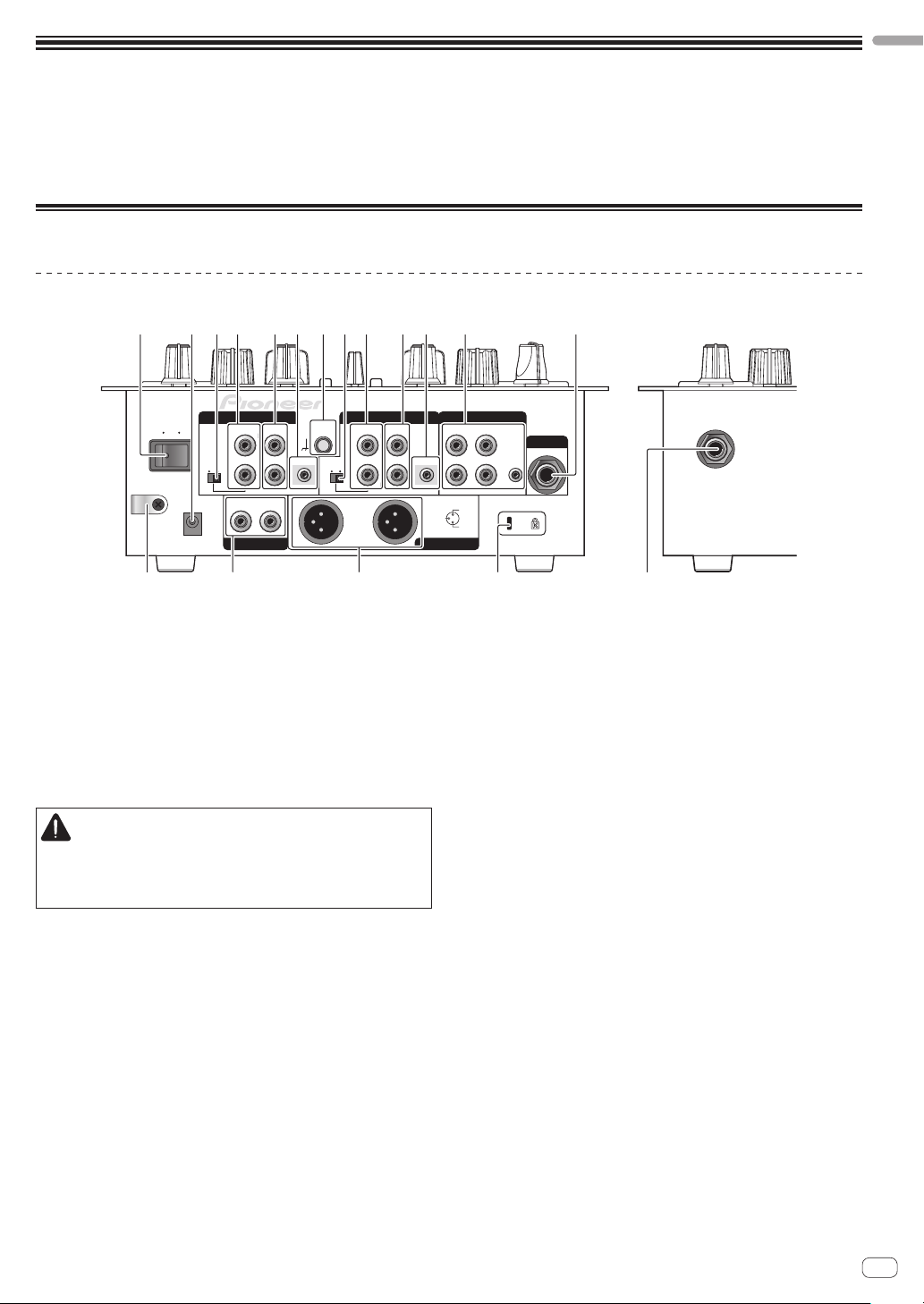
部件名称
背面板,正面板
321 4 5 86 4 5 67 3 9
中文(简体)
ON
ݢኑ༕
࣋
OFF
CH-2
PHONO / LINE CD
L
LINE PHONO
R
RL
DC IN
b dc a
SIGNAL
GND
CONTROL
LINE PHONO
L
R
CH-1 AUX
PHONO / LINE CD
L
R
1 ON/OFF 开关(第 9页)
开启和关闭本机电源。
2 DC IN 端子
使用随附的 AC 适配器连接到电源插座(安装了电源插
头 )。
连接 AC 适配器之前,等待直至所有设备的连接完成。
仅使用随附的 AC 适配器。
3 PHONO/LINE 选择器开关(第 6页)
切换 [PHONO/LINE] 端子的功能。
小心
切换 [PHONO/LINE] 选择器开关时,将
[MASTER LEVEL] 设为 [- ∞ ]。 请注意,可能产生噪
声且以高音量输出声音。
4 PHONO/LINE 端子(第 6页)
在此处连接唱机电平输出设备(模拟播放机(用于 MM
盒式磁带)等)或线路电平输出设备(DJ 播放机等)。
根据连接的设备,使用本机后面板上的 [PHONO/
LINE] 选择器开关切换端子的功能。
CONTROL
23
3 COLD
MASTER 1MASTER 2
L
R
1GND
2 HOT
MIC
1
8 AUX 端子(第 6页)
连接到外部设备(计算机、便携式音频装置、电视机、
合成器等)的输出端子。
9 MIC 端子(第 6页)
连接至麦克风。
a MASTER 1 端子(第 6页)
在此处连接通电的扬声器等。
! 与 XLR 连接器类型平衡输出端兼容。
b MASTER 2 端子(第 6页)
在此处连接通电的扬声器等。
! 与 RCA 针插孔类型不平衡输出端兼容。
c 绳钩
在此处钩住 AC 适配器电源线。
d 防窃锁槽
e PHONES 插孔(第 6页)
此处连接耳机。
e
5 CD 端子(第 6页)
连接到 DJ 播放机或其他线路电平设备。
6 CONTROL 端子(第 6页)
使用控制线(先锋 DJ 播放机随附)连接。
7 SIGNAL GND 端子(第 6页)
在此处连接模拟播放机的接地线。连接模拟播放机时,
这有助于降低噪声。
Zhcn
5
Page 6
连接输入/输出端子
! 在搭建包含计算机、音频接口等的 DVS(数字唱盘系统)时,请注意将音频接口连接到本机的输入端子,并切换输
入选择器的设定。
同样请参阅 DJ 软件和音频接口的使用说明书。
背面板,正面板
ፚݢኑنᏰ
łń ിධ
˄ཱུࡒ˅
ሕ൮༕ڵؠࠍ
ߓ
ሕ൮༕ؠࠍ
ֶಅ֊
࣋
ON
OFF
ݢኑ༕
ጸಅ֊
ሕ൮ݢେ
RL
L
R
AUDIO
OUT
CONTROL
USB
CH-2
PHONO / LINE CD
LINE PHONO
RL
DC IN
R
SIGNAL
GND
L
L
CONTROL
R
R
L
R
L
PHONO / LINE CD
LINE PHONO
CH-1 AUX
L
L
CONTROL
R
R
ኑᆲ໌ධȂᏠȂܐධ݃
3 COLD
MASTER 1MASTER 2
૿፟ღ
R R
1GND
2 HOT
INPUT
1
2
34EQ
POWER
L
LL
R
߭ஂ˖
ńŅŋĮĴĶıġ
1
23
ಠ؆Ņŋ ؆
ፚሕ൮༕ڵޤᏊፚݓޤᏊ
ݓღ
ሕ൮ݢେ
ఴࠞ
ఴࠞღ
ፚఴࠞ
MIC
1
צᄔሕ൮ົֻ
ሕ൮ݢେ
ፚሕ൮༕ڵޤᏊ
ݢ
ሕ൮ݢେ
ፚሕ൮༕ڵޤᏊ
INPUT
1
2
34EQ
POWER
ڈධ
ߓღ
ሕ൮ݢେ
ሕ൮ݢେ
1 要使用渐变器启用功能,请连接控制线(第 11页)。
仅当连接到先锋 DJ 播放机时才可使用渐变器启用功能。
绳钩
松开绳钩的螺丝并在钩子下方卡住 AC 适配器电源线。
໑ࢦ
ݢኑ༕
DC IN
R
LR
MASTER 2
łń ിධݢኑღ
! 将绳钩置于儿童触及范围之外。 如果儿童不慎吞
食,应立即就医。
Zhcn
6
ፚሕ൮༕ޤᏊ
ሕ൮ݢେ
ፚሕ൮༕ڵޤᏊ
Page 7
关于 AC 适配器
中文(简体)
安全说明书
为了确保人身安全并充分发挥本机性能,请阅读并遵循
安全说明书。
请阅读并妥善保管说明书
请阅读本产品提供的所有操作和用户信息。
清洁
使用湿布清洁外壳。 避免使用包括液体、气溶胶或酒精
基清洁产品在内的任何流体。
水或湿气
避免在水或其它流体来源附近运行或定位本产品。
附件
不得将本产品置于不稳定的推车、支架或工作台上。 否
则本产品可能掉落并导致严重损坏。
通风
使用时不得阻塞或覆盖本产品。 除非正确通风,否则不
应将本机放在内置装置中。
环境
避免将本产品置于暴露于大量灰尘、高温、高湿或经受过
量振动或冲击的位置。
电源
仅在推荐的电源上运行本产品。 如果不确定电源,请咨
询先锋授权代表。
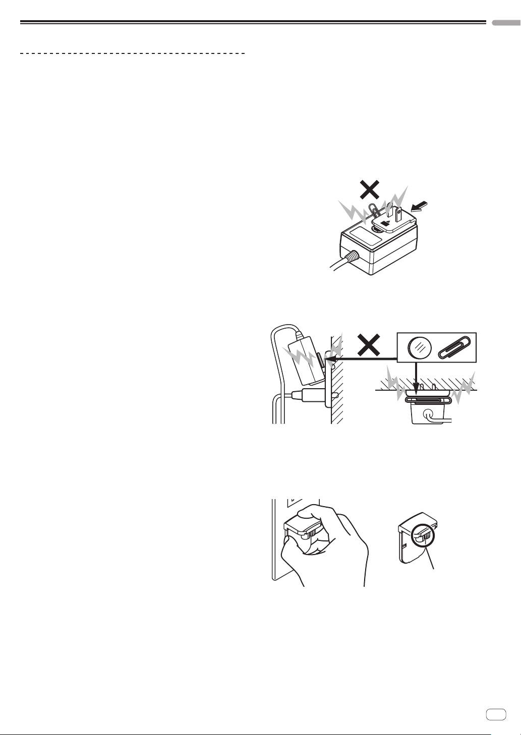
检查并确认 AC 适配器或电源插头未出现异常,然后使用
指定程序将电源插头插入 AC 适配器的指定位置,直至听
到咔嗒声。 有关详情,请参阅 第 8页 上
安装电源插头
如果 AC 适配器或电源插头出现异常,联系最近的先锋授
权维修中心或经销商执行修理工作。
! 不得将 AC 适配器线缠绕在颈部。 否则可能会导致窒
息。
! 使用本机时不得使用硬币、回形针或其它金属物体,这
些物体可能会卡在 AC 适配器与电源插头之间。 否则
会导致短路、火灾或电击。
! 在墙壁插座上安装 AC 适配器时,确保 AC 适配器与墙
壁插座之间无空隙。 接点出现故障或硬币、回形针或
其它金属物体卡在空隙中会导致短路、火灾或电击。
ሱוȂইᄳጦডඝྊ༥႘࿒
。
电源线保护
拔下本机插头时,拉动插头而不是电源线。 不得用湿手
持握电源线或插头 ;否则可能导致短路或电击。 禁止任
何物品卡住或靠在电源线上,不得置于人行道中。
电源
安装本机或其它硬件设备之前,关闭系统。
过载
避免将过多设备连接到一个墙壁插座或电源,否则会导
致火灾或短路。
物体和液体进入
切勿将不适当的物体推入设备。 避免任何液体溅落到驱
动器内部或外部。
维修
打开或拆除盖板可能会导致电击或其它危险。 请联系先
锋授权服务代表修理本产品(请参阅随附的维修和支持
卡 )。
损坏,要求维修
以下情况下,拔下本机插头并请有资质的维修人员进行
维修 :
! 电源线、插头或机身损坏时。
! 液体溅落或物体掉入产品中时。
! 产品暴露于雨水或水时。
! 遵循使用说明书但产品无法正常运行。 仅调节使用说
明书涵盖的控制装置。 若不正确调节其它控制装置,
可能导致损坏,必须由有资质的技术人员将本机恢复
到正常运行状态。
! 产品性能出现明显变化时,表示需要维修。
فע
ݾؠ
! 如果 AC 适配器电源线脱扣或遭到撞击,电源插头可能
脱离 AC 适配器但保持处于电源插座中。 如果出现此
种情况,用干手拔下保持处于插座中的电源插头,如
下图所示持握且不触摸金属部件。 拔下插头时不得使
用任何工具。
ข႙ۂ
Zhcn
7
Page 8
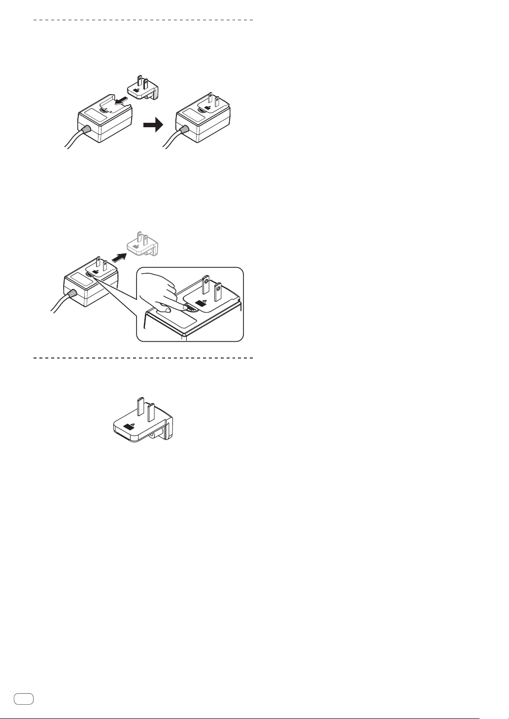
安装电源插头
如下图所示,沿着 AC 适配器装置中的导轨滑动电源插头,
然后压入直至听到咔嗒声。
拔下电源插头
按下 AC 适配器装置上的 [PUSH] 按钮时,如下图所示朝远
离适配器的方向滑动电源插头,以拔下插头。
一旦安装了电源插头,无需拔下。
电源插头
本产品随附了以下所示电源插头。
Zhcn
8
Page 9
操作
中文(简体)
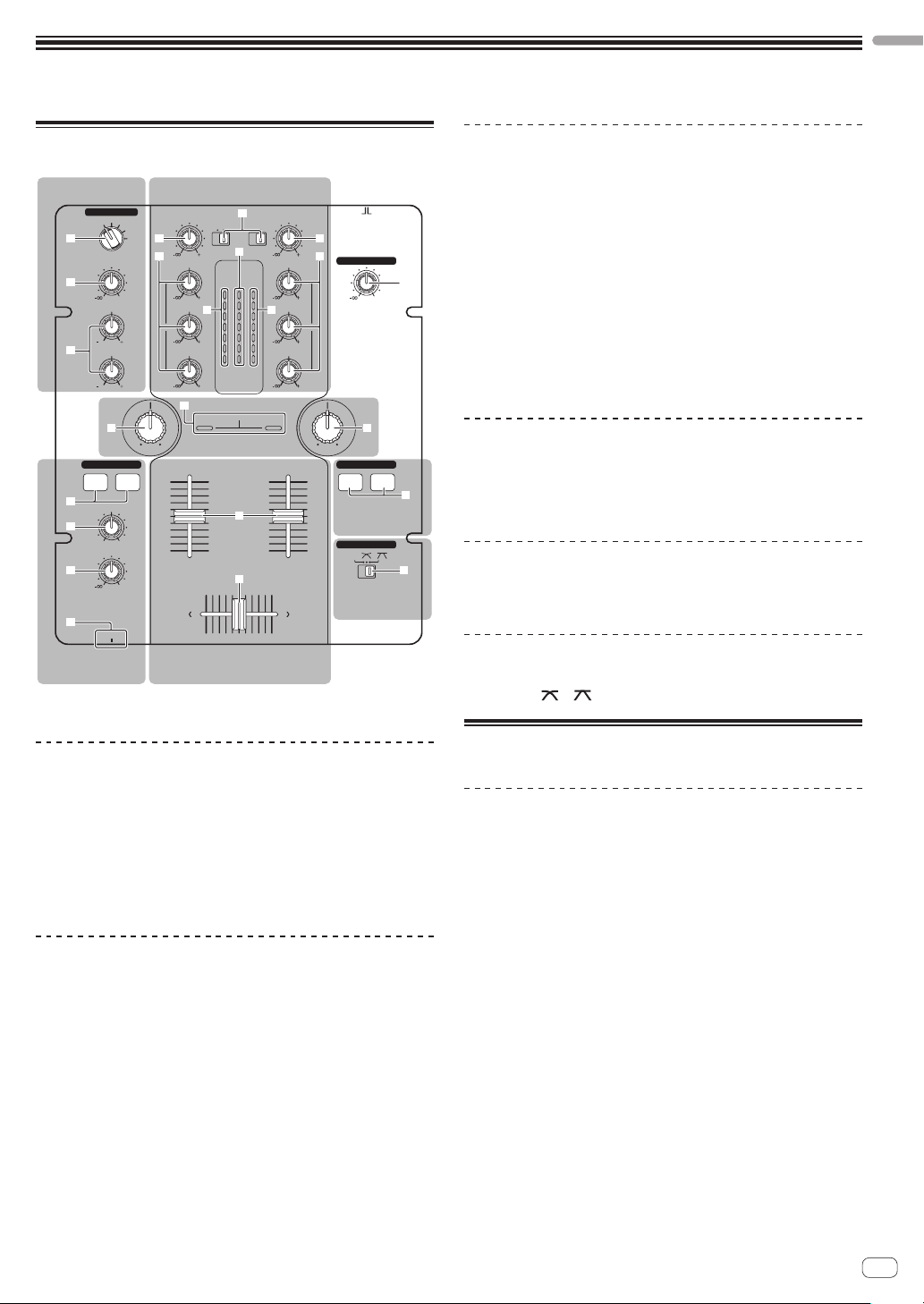
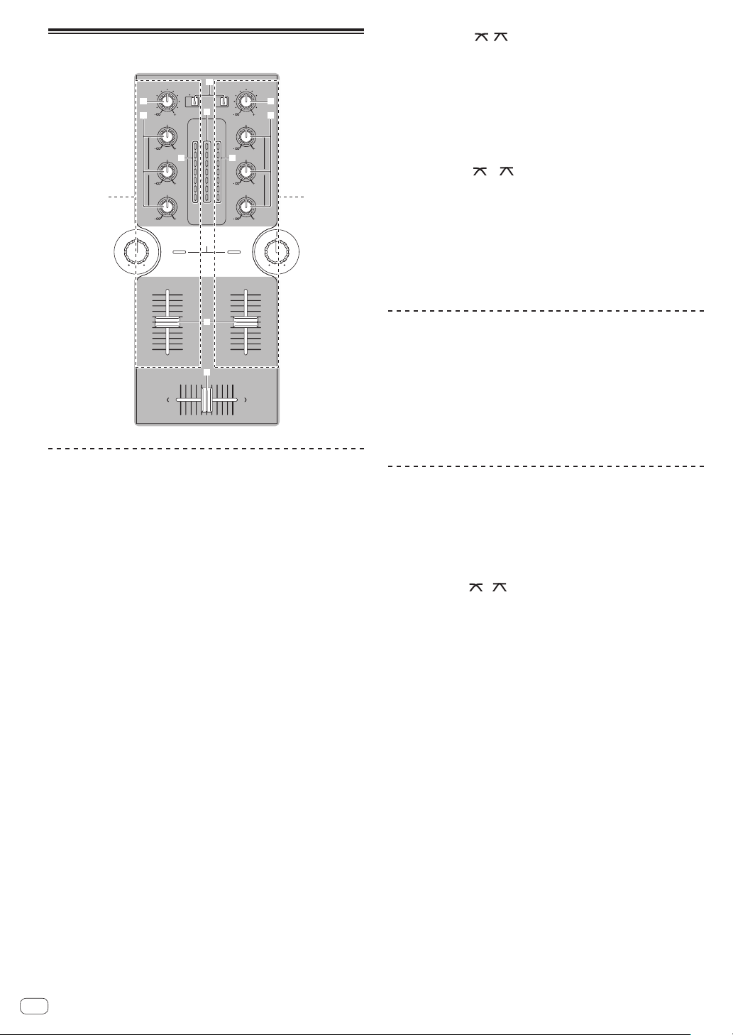
控制面板
MIC/AUX
MIC/AUX
MIC
2 a
LEVEL
3
LOW
4
HEADPHONES
CH-1 CH-2
5
MIXING
6
LEVEL
7
8
PHONES
ߓؠࠍ
ؠࠍ
OFF
AUX 1
AUX 2
AUX 3
b
0
HI
1212
1212
LPFHPF LPF HPF
ছሕධؠࠍ
9
TRIM
PHONO
CD
/LINE
9
HI
MASTER
CH-1 CH-2
OVER
9
+4
MID
d d
LOW
g
+2
-
9
-
-
dB
LEVEL
9
SOUND COLOR FILTER
EQ EQ
TRIM
PHONO
CD
/LINE
c
HI
OVER
+4
MID
+2
0
0
6
-
6
12
-
12
LOW
18
-
18
dB
ఌ؉ධؠࠍ
e
MASTERCUE
0
CH-1 CH-2
f
ছሕධؠࠍ
9
9
9
9
a
b
ONOFF
2 CHANNEL DJ MIXER
DJM-250
MASTER LEVEL
0
hh
FADER START
CH-1 CH-2
קධතވ
ؠࠍ
CROSS FADER
THRU
هקධ
ؠࠍ
混音器部分
在基本 DJ 混音时两组音频信号可以单独调节(第 10页)。
9 CD、PHONO/LINE 输入选择器开关
a TRIM 控制
b EQ(HI、MID、LOW)控制装置
1
c 主电平指示灯
d 声道电平指示灯
e 声道渐变器
f 交叉渐变器
滤波器部分
i
j
g SOUND COLOR FILTER 指示灯
h SOUND COLOR FILTER 控制装置
渐变器启动部分
i CH-1、CH-2 按钮(渐变器启动部分)
交叉渐变器部分
1 MASTER LEVEL 控制装置(第 10页)
MIC/AUX 部分
本部分可处理麦克风或外部设备(计算机、便携式音频装
置、电视机、合成器等)的声音(第 12页)。
2 MIC、OFF、AUX 1、AUX 2、AUX 3 输入选择器开关
3 LEVEL 控制装置(MIC/AUX 部分)
4 HI、LOW 控制装置
耳机部分
输入到本机的声音可以使用耳机检查(第 12页)。
5 CH-1、CH-2 按钮(耳机部分)
6 MIXING 控制装置
7 LEVEL 控制装置(耳机部分)
8 PHONES 插孔
j THRU、 、 (交叉渐变器曲线选择器开关)
关于本机的电源开关
要开启电源
将本机后面板上的 [ON/OFF] 开关设为 [ON]。
这样将开启本机电源(第 5页)。
Zhcn
9
Page 10
基本操作(混音器部分)
9
TRIM
PHONO
CD
CD
a
b
EQ EQ
1 2
LPFHPF LPFHPF
/LINE
9
HI
MASTER
CH-1 CH-2
OVER
9
MID
d d
9
LOW
9
SOUND COLOR FILTER
c
+4
+2
0
-
6
-
12
-
18
dB
LEVEL
OVER
+4
+2
0
-
6
-
12
-
18
dB
PHONO
/LINE
4 切换 [THRU、 、 ](交叉渐变器曲线选择器开关)j。
这样将切换交叉渐变器的曲线特征。 有关详情,请参阅 第
11
页 上
选择交叉渐变器的曲线特征(交叉渐变器部分)
TRIM
a
9
b
HI
9
MID
9
LOW
5 移动交叉渐变器 f。
切换声音从扬声器输出的声道。
— 左 侧 :[ CH-1] 声音输出。
— 中置 :声音 [CH-1]和[CH-2] 混音输出。
— 右 侧 :[ CH-2] 声音输出。
! 当[THRU、
、 ](交叉渐变器曲线选择器)开关
设定为 [THRU] 时,不需要该操作。
。
6 顺时针旋转 [MASTER LEVEL] 控制装置 1。
9
声音从扬声器输出。
控制面板上主电平指示灯 c 亮起。
调节 [MASTER LEVEL],在曲目音量最高处(高潮等)桔
黄色指示灯亮起。
请注意红色指示灯应当没有亮起,否则声音会失真。
e
CH-1 CH-2
f
输出声音
输出声音之前请检查本机是否正确连接到 DJ 播放机等。
有关连接的说明,请参阅 第6页 上
将连接到 [MASTER 1]和[MASTER 2] 端子的有源扬声
器的音量设为合适的电平。 请注意,如果音量设定过高,
将以高音量输出声音。
有关声音监听的说明,请参阅 第 12页 上
音(耳机部分)
要输出声道 1[CH-1] 1 声音
。
要输出声道 2([CH-2] ) 2 声音,请使用 [CH-2] 替换
[CH-1] 执行下列步骤。
1 切换 [CH-1] 1 [ CD, PHONO/LINE] 输入选择器开关 9。
从连接至本机的设备中为 [CH-1] 选择输入源。
— [ CD] :选择连接到 [CD] 端子的 DJ 播放机。
— [ PHONO/LINE]:选择连接到 [PHONO/LINE] 端子
的设备。
2 顺时针旋转 [CH-1] 1 [TRIM] 控制装置 a。
调节输入到 [CH-1] 端子的音频电平。
当音频信号正确输入 [CH-1] 时,相应的 [CH-1] 声道电
平指示灯 d 亮起。
调节 [TRIM] 控制装置,使橙色指示灯在曲目音量最高处
(高潮等)亮起。
请注意红色指示灯应当没有亮起,否则声音会失真。
3 朝远离您的方向移动 [CH-1] 1 声道渐变器 e。
从[CH-1] 端子输出的声音电平得到调节。
连接输入/输出端子
监听耳机的声
调节音质
旋转 [CH-1] 1 或[CH-2] 2 EQ(HI、MID、LOW)控
制装置 b。
有关可通过各控制装置调节的声音范围,请参阅 第 14页
上规格。
! 还可按逆时针方向旋转控制旋钮,完全去除该范围的
声音(隔音器功能)。
使用渐变器混音
。
预先准备本机,这样 [CH-1] 1 的声音就可从扬声器输
出。有关准备的说明,请参阅 第 10页 上
使用声道渐变器混音
1 将 [THRU、
、 ](交叉渐变器曲线选择器开关)j
设为 [THRU]。
2 切换 [CH-2] 2 [ CD, PHONO/LINE] 输入选择器开关 9。
3 顺时针旋转 [CH-2] 2 [TRIM] 控制装置 a。
4 按耳机部分中的 [CH-2] 按钮 5。
从耳机监听 [CH-2] 声音。
5 旋转 [MIXING] 控制装置 6。
调节 [MASTER 1]或[MASTER 2] 端子([CH-1] 声音)
和[CH-2] 声音输出的声音的监听音量平衡。
6 操作连接到 [CH-2] 端子的 DJ 播放机。
当检查耳机输出的声音时,调节 [CH-2] 音轨的拍速以匹
配[CH-1] 音轨的拍速。
7 当移动 [CH-2] 2 声道渐变器到后侧同时,移动 [CH-1]
1 声道渐变器到前侧。
当检查扬声器输出的声音时,操作声道渐变器使用
[CH-2] 声音替代 [CH-1] 声音。
一旦扬声器只输出 [CH-2] 声音时,表示混音完成。
输出声音
。
10
Zhcn
Page 11

使用交叉渐变器混音
1 将 [THRU、
设为 [
、 ](交叉渐变器曲线选择器开关)j
]或[ ]。
2 操作 [CH-2] 2。
按 第 10页 上
使用声道渐变器混音
下的步骤 2 至 6 操作。
3 逐渐向右移动交叉渐变器 f。
当检查扬声器输出的声音时,操作交叉渐变器使用
[CH-2] 声音替代 [CH-1] 声音。
一旦扬声器只输出 [CH-2] 声音时,表示混音完成。
使用滤波器功能(滤波器部分)
选择交叉渐变器的曲线特征(交叉渐变器部分)
CROSS FADER
THRU
j
— [ THRU] :不打算使用交叉渐变器时选择此选项。
— [ ] :对于渐升曲线,设定到此位置。
— [ ] :对于陡升曲线,设定到此位置。(当交叉渐变
器偏离左侧或右侧时,声音立即从对面侧输出。)
中文(简体)
g
1 2
LPFHPF LPF HPF
SOUND COLOR FILTER
hh
每个声道均配备了 SOUND COLOR FILTER 功能,只需旋转
较大控制装置即可实现滤波器音效。
可通过旋转 [SOUND COLOR FILTER] 控制装置 h 删除
高音或低音。
旋转 [CH-1] 1 或者 [CH-2] 2
[SOUND COLOR FILTER] 控制装置 h。
音效应用于声音,指示灯的颜色发生改变。
如下表所示,音效类型和指示灯颜色随 [FILTER] 控制装
置旋转的方向而有所不同。
旋转方向 音效说明 指示灯
左侧
应用高音渐隐音效。
(LPF :低通滤波器)
红色(闪烁)
中心 - 橙色(亮起)
右侧
应用低音渐隐音效。
(HPF:高通滤波器)
绿色(闪烁)
使用 SOUND COLOR FILTER 控制装置混音
预先准备本机,这样 [CH-1] 1 的声音就可从扬声器输
出。有关准备的说明,请参阅 第 10页 上
有关声音监听的说明,请参阅 第 12页 上
音(耳机部分)
。
1 操作交叉渐变器和 [CH-2] 2。
按 第 10页 上
使用声道渐变器混音
输出声音
。
监听耳机的声
下的步骤 2 至 6 操作。
使用渐变器开始播放先锋 DJ 播放机(渐变
器启动部分)
FADER START
CH-1 CH-2
i
如果使用控制电缆(随 DJ 播放机附带)连接先锋 DJ 播放
机,可以使用本机的渐变器控制 DJ 播放机的播放和其他
操作。
仅当连接到先锋 DJ 播放机时才可使用渐变器启用功能。
事先连接本机和先锋 DJ 播放机。有关连接的说明,请参
阅 第 6页 上
要利用声道渐变器启动播放
1 将 [THRU、 、 ](交叉渐变器曲线选择器开关)j
设为 [THRU]。
2 按渐变器启动部分中的 [CH-1]或[CH-2] 按钮 i。
开启渐变器启动功能。
3 将声道渐变器 e 移至最前侧。
4 在 DJ 播放机上设定指示。
DJ 播放机在指示点处暂停播放。
5 朝远离您的方向移动声道渐变器 e。
在 DJ 播放机上开始播放。
! 若将声道渐变器设回初始位置,播放机立即返回已经
设定的指示点并暂停播放(返回指示)。
连接输入/输出端子
。
2 完全顺时针旋转 [CH-2] 2 [SOUND COLOR FILTER]
控制装置 h。
3 朝远离您的方向移动 [CH-2] 2 声道渐变器 e。
4 从中心逆时针旋转 [CH-1] 1
[SOUND COLOR FILTER] 控制装置 h 时,朝中心旋转
[CH-2] 2 [SOUND COLOR FILTER] 控制装置 h。
检查扬声器的声音输出时,操作
[SOUND COLOR FILTER] 控制装置 h 并更换 [CH-1]和
[CH-2] 声音。
向前移动 [CH-1] 1 声道渐变器 e。 一旦扬声器只输出
[CH-2] 声音,即表示混音完成。
Zhcn
11
Page 12

要利用交叉渐变器启动播放
使用麦克风或外部设备(MIC/AUX 部分)
1 将 [THRU、 、 ](交叉渐变器曲线选择器开关)j
设为 [
]或[ ]。
2 按渐变器启动部分中的 [CH-1]或[CH-2] 按钮 i。
开启渐变器启动功能。
3 移动交叉渐变器 f。
将交叉渐变器移向与要使用渐变器启动功能的声道相反
的一侧。
4 在 DJ 播放机上设定指示。
DJ 播放机在指示点处暂停播放。
5 移动交叉渐变器 f。
在 DJ 播放机上开始播放。
! 若将交叉渐变器设回初始位置,播放机立即返回已经
设定的指示点并暂停播放(返回指示)。
监听耳机的声音(耳机部分)
HEADPHONES
CH-1 CH-2
5
MIXING
6
7
LEVEL
MASTERCUE
0
MIC/AUX
OFF
MIC
AUX 1
AUX 2
LEVEL
LOW
AUX 3
0
HI
1212
1212
2
3
4
1 切换 [MIC、OFF、AUX 1、AUX 2、AUX 3] 输入选择
器开关 2。
— [ MIC] :选定连接到 [MIC] 端子的麦克风。
— [ AUX1–3]:选择连接到 [AUX1–3]端子的外部设备。
2 顺时针旋转 MIC/AUX 部分中的 [LEVEL] 控制装置 3。
麦克风或外部设备的声音从扬声器输出。
调节音质
旋转 MIC/AUX 部分中的 [HI]或[LOW] 控制装置 4。
有关可通过各控制装置调节的声音范围,请参阅 第 14页
上规格。
8
PHONES
1 将耳机连接至 [PHONES] 端子。
有关连接的说明,请参阅 第6页 上
连接输入/输出端子
2 按耳机部分中的 [CH-1]或[CH-2] 按钮 5。
选择要监听的声道。
— [ CH-1]:监听[CH-1] 的声音。
— [ CH-2]:监听[CH-2] 的声音。
! 此项操作不需要监听 [MASTER 1]或[MASTER 2]
(主声道)声音。
3 旋转 [MIXING] 控制装置 6。
— 当反方向旋转时:[CH-1]和[CH-2] 音量变得较高。
— 中 置 : [ CH-1]和[CH-2] 声音的音量与 [MASTER
1]和[MASTER 2] 声音具有相同电平。
— 当顺时针旋转时: [MASTER 1]和[MASTER 2]的
音量变得较高。
4 顺时针旋转耳机部分中的 [LEVEL] 控制装置 7。
声音从耳机输出。
! 再按一次耳机部分中的 [CH-1]或[CH-2] 按钮时,将
取消监听。
! [MASTER 1]和[MASTER 2] 监听无法取消。
。
12
Zhcn
Page 13

附加信息
故障排除
! 不正确的操作通常会被误认为是故障。 如果您认为本部件存在问题,请检查以下几点。 某些时间故障来自于另一
个部件。 检查其它正在使用的部件和电器。 如果以下项目检查后未能纠正故障,则请向距您最近的先锋授权维修
中心或与您的经销商联系,以进行维修工作。
! 本机可能因静电或其它外部因素而无法正常工作。在此情况下,可关闭电源等待 1 分钟,然后再打开电源,也许能
恢复到正常工作。
故障问题 检查 排除方法
电源无法开启。 是否正确连接随附的 AC 适配器? 将随附的 AC 适配器正确连接到电源插座。 ( 第 6页 )
将随附 AC 适配器的电源线正确固定到本机的绳钩。
(第6页)
电源的 [ON/OFF] 开关是否设为
[ON]?
无声音或声音小。 [CD、PHONO/LINE] 输入选择器
开关是否设定到正确位置?
本机后面板上的 [PHONO/LINE]
选择器开关是否设定到正确位置?
[TRIM]、[ 声道渐变器 ]、[ 交叉
渐变器]和[MASTER LEVEL]控
制旋钮是否设定为正确位置?
连接的有源扬声器等是否正确设定?
接线电缆是否正确连接? 正确连接接线电缆。 ( 第 6页 )
端子和插头是否脏污? 进行连接之前,清洁端子和插头。
声音失真。 [MASTER LEVEL] 位置是否正确
设定?
[TRIM] 位置是否正确设定? 调节 [TRIM] 控制装置,使声道电平指示灯的橙色指
无法交叉渐变。 [THRU、
曲线选择器)开关是否设定到
[THRU]?
渐变器无法启动 DJ 播放机。 渐变器启动部分中的 [CH-1]或
[CH-2] 按钮是否设定到关闭位置?
控制线是否正确连接? 利用控制线连接本机和 DJ 播放机。 ( 第 6页 )
音频电缆是否正确连接? 利用音频电缆连接本机和 DJ播放机的音频输出端子。
当本机的 [PHONO/
LINE] 端子连接模拟播放
机时,声音会出现失真。
否则即使启用 [TRIM] ,声
道电平指示灯也不会出现
变化。
您的模拟播放机是否已连接内置
唱机均衡器?
是否已使用计算机专用音频接口
连接模拟播放机和本机?
、 ](交叉渐变器
将电源的 [ON/OFF] 开关设为 [ON]。 ( 第 9页 )
将[CD、PHONO/LINE] 输入选择器开关切换到声道
的输入源。 ( 第 10页 )
使用本机后面板上的 [PHONO/LINE]选择器开关切换
端子的功能。 ( 第 5页 )
设定 [TRIM]、[ 声道渐变器 ]、[ 交叉渐变器 ] 和
[MASTER LEVEL] 控制旋钮为正确位置。 ( 第 10页 )
正确设定有源扬声器等上的外部输入选择、音量等。
调节 [MASTER LEVEL] 控制装置,使主电平指示灯的
橙色指示灯在峰值电平时亮起。 ( 第 10页 )
示灯在峰值电平时亮起。 ( 第 10页 )
将[THRU、 、 ](交叉渐变器曲线选择器)开关
设定到 [THRU] 外的位置。 ( 第 10页 )
将渐变器启动部分中的 [CH-1]或[CH-2] 按钮设定到
开启位置。 ( 第 11页 )
(第6页)
如果模拟播放机配备有内置唱机均衡器,请将其连接
到[CD] 端子。 ( 第 6页 )
如果内置唱机均衡器的模拟播放机上有 PHONO/LINE选
择器开关,请切换到 PHONO。
如果计算机音频接口的输出是线路电平,请将其连接
到[CD] 端子。 ( 第 6页 )
如果模拟播放机上有 PHONO/LINE 选择器开关,请切换
到 PHONO。
中文(简体)
Zhcn
13
Page 14

方块图
CD1
LINE1/
PHONO1
CD2
LINE2/
PHONO2
MIC
OFF
AUX 1
AUX 2
AUX 3
LEVEL
TRIM
TRIM
2Band
EQ
3Band
EQ
3Band
EQ
FILTER
FILTER
HP MASTER
HP CH 1 HP OUT
HP CH 2
关于商标和注册商标
! 先锋是日本先锋公司的注册商标。
! 此处提及的公司和产品名称是其各自所有者的商标。
! 当播放本机采集的音乐文件时,我们恳请您尊重版权。
规格
AC 适配器
电源 ................AC 100 V 至 240 V,50 Hz/60 Hz
额定电源 .................................. 800 mA
额定输出 ............................. DC 5 V,3 A
概述 – 主机
主机质量 .................................. 3.1 kg
最大尺寸
......240 mm(宽)x 107.7 mm(高)x 300.2 mm(深)
允许运行温度 ................... +5 ° C 至 +35 ° C
容许的工作湿度 ............... 5 % 至 85 %(无冷凝)
音频部分
取样率 .................................... 48 kHz
A/D、D/A 转换器 .............................24 位
频率特征
CD/LINE/AUX/MIC .............. 20 Hz 至 20 kHz
标准输出电平/负载阻抗/输出阻抗
MASTER 1 ................. +6 dBu/10 kW/330 W
MASTER 2 .................. +2 dBu/10 kW/1 kW
PHONES .................... +2 dBu/32 W/33 W
额定输出电平/负载阻抗
MASTER 1 ....................... +22 dBu/10 kW
MASTER 2 ....................... +18 dBu/10 kW
声道均衡器特征
HI ..................... - ∞ 至 + 9 dB(13 kHz)
MID .................... - ∞ 至 + 9 dB(1 kHz)
LOW ..................... - ∞ 至 +9 dB(70 Hz)
MIC/AUX 均衡器特征
HI ...................-12 dB 至 +12 dB (10 kHz)
LOW .................-12 dB 至 +12 dB (100 Hz)
CH 1
LEVEL METER
HP CH 1
CH 2
LEVEL METER
HP CH 2
HP MIX
CH 1
FADER
CH 2
FADER
HP VOL
CROSS
FADER
MASTER
VOL
HP MASTER
输入/输出端子
CD 输入端子
RCA 针插孔 .................................2组
PHONO/LINE 输入端子
RCA 针插孔 .................................2组
MIC 输入端子
电话插孔(Ø 6.3 mm) .......................1组
AUX 输入端子
RCA 针插孔 .................................2组
微型电话插孔(Ø 3.5 mm) ...................1组
MASTER 输出端子
RCA 针插孔 .................................1组
BALANCED OUTPUT 输出端子
XLR 连接器 .................................1套
PHONES 输出端子
立体声电话插孔(Ø 6.3 mm) .................1组
CONTROL 端子
微型电话插孔(Ø 3.5 mm) ...................2组
! 本产品规格与设计若有变更,恕不另行通知。
! © 2011 日本先锋公司。版权所有。
MASTER LEVEL
METER
MASTER 1 OUT
MASTER 2 OUT
14
Zhcn
Page 15

中文(简体)
Zhcn
15
Page 16

Thank you for buying this Pioneer product. Please read through these operating instructions so you will know how to operate your model properly. After
you have finished reading the instructions, put them away in a safe place for future reference.
In some countries or regions, the shape of the power plug and power outlet may sometimes differ from that shown in the explanatory drawings.
However the method of connecting and operating the unit is the same.
WARNING
This equipment is not waterproof. To prevent a fire or
shock hazard, do not place any container filled with
liquid near this equipment (such as a vase or flower
pot) or expose it to dripping, splashing, rain or
moisture.
D3-4-2-1-3_A1_En
If the AC plug of this unit does not match the AC
outlet you want to use, the plug must be removed
and appropriate one fitted. Replacement and
mounting of an AC plug on the power supply cord of
this unit should be performed only by qualified
service personnel. If connected to an AC outlet, the
cut-off plug can cause severe electrical shock. Make
sure it is properly disposed of after removal.
WARNING
Before plugging in for the first time, read the following
section carefully.
The voltage of the available power supply differs
according to country or region. Be sure that the
power supply voltage of the area where this unit
will be used meets the required voltage (e.g., 230 V
or 120 V) written on the side panel.
D3-4-2-1-4*_A1_En
WARNING
To prevent a fire hazard, do not place any naked flame
sources (such as a lighted candle) on the equipment.
D3-4-2-1-7a_A1_En
Operating Environment
Operating environment temperature and humidity:
+5 °C to +35 °C (+41 °F to +95 °F); less than 85 %RH
(cooling vents not blocked)
Do not install this unit in a poorly ventilated area, or in
locations exposed to high humidity or direct sunlight (or
strong artificial light)
D3-4-2-1-7c*_A1_En
This product is for general household purposes. Any
failure due to use for other than household purposes
(such as long-term use for business purposes in a
restaurant or use in a car or ship) and which requires
repair will be charged for even during the warranty
period.
K041_A1_En
The equipment should be disconnected by removing
the mains plug from the wall socket when left unused
for a long period of time (for example, when on
vacation).
D3-4-2-2-1a_A1_En
CAUTION
The ON/OFF switch on this unit will not completely
shut off all power from the AC outlet. Since the power
cord serves as the main disconnect device for the
unit, you will need to unplug it from the AC outlet to
shut down all power. Therefore, make sure the unit
has been installed so that the power cord can be
easily unplugged from the AC outlet in case of an
accident. To avoid fire hazard, the power cord should
also be unplugged from the AC outlet when left
unused for a long period of time (for example, when
on vacation). D3-4-2-2-2a*_A1_En
POWER-CORD CAUTION
Handle the power cord by the plug. Do not pull out the
plug by tugging the cord and never touch the power
cord when your hands are wet as this could cause a
short circuit or electric shock. Do not place the unit, a
piece of furniture, etc., on the power cord, or pinch the
cord. Never make a knot in the cord or tie it with other
cords. The power cords should be routed such that they
are not likely to be stepped on. A damaged power cord
can cause a fire or give you an electrical shock. Check
the power cord once in a while. When you find it
damaged, ask your nearest PIONEER authorized
service center or your dealer for a replacement.
S002*_A1_En
En
2
Page 17

Contents
How to read this manual
The names of displays, menus, and buttons in this manual are enclosed
in brackets. (e.g. [MASTER] channel, [ON/OFF], [File] menu)
Before start
Features ....................................................................................................... 4
System setup example ............................................................................... 4
What’s in the box ........................................................................................ 4
Connections
Names of Parts ........................................................................................... 5
Connecting the input/output terminals .................................................... 6
About the AC adapter ................................................................................. 7
Operation
Control panel ............................................................................................... 9
About the power switch of this unit .......................................................... 9
Basic operations (mixer section) ............................................................ 10
Using the filter function (filter section) ................................................... 11
Selecting the crossfader’s curve characteristics
(crossfader section) .................................................................................. 11
Starting playback of a Pioneer DJ player using the fader
(fader start section) .................................................................................. 11
Monitoring the sound over headphones (headphones section) .......... 12
Using a microphone or external device (MIC/AUX section) ................. 12
Additional information
Troubleshooting ........................................................................................ 13
Block Diagram .......................................................................................... 13
About trademarks and registered trademarks ...................................... 14
Specifications............................................................................................ 14
En
3
Page 18

Before start
Features
This unit is a DJ mixer that carries over the technology of the Pioneer DJM series, the world standard in club sound. It is a standard type unit equipped
with the basic functions required for mixing, enabling full-fledged DJ play easily.
SOUND COLOR FILTER
Each channel is equipped with a SOUND COLOR FILTER function by
which filter effects can be achieved simply by turning a large control.
This lets you arrange and mix tracks intuitively for DJ performances.
MIC/AUX INPUT
This unit is equipped with three sets of AUX inputs for input of audio
signals from external devices (computers, portable audio sets, TVs,
synthesizers, etc.), as well as a microphone input. It can be used not only
for DJ performances, but also as a pre-amp to appreciate music.
3-BAND EQUALIZER
This unit is equipped with a 3-band equalizer allowing the volume of
the high, medium and low frequency ranges to be adjusted separately.
Not only can the tone be adjusted to your tastes, the sound for a certain
range can be turned completely off by turning the control all the way
counterclockwise (isolator function).
XLR OUTPUT
This unit is equipped with XLR balanced outputs featuring little loss of
audio signal quality, enabling DJ performances with high sound quality.
Also, it can be connected to powered speakers or other devices supporting XLR inputs without any changes to the terminals.
System setup example
A DJ system like the one shown on the diagram below can be achieved by combining this unit with a DJ player and peripheral equipment.
Synthesizers,
computers,
portable audio devices,
microphones, etc.
TIME MODE
REMAIN
MS
AUTO CUE
A.CUE
INFO
DISPLAY
BROWSE
USB
STOP
UTILITY
SOURCE SELECT
MP3/AAC
WAV/AIFF
IN/CUEOUT
TRACK SEARCH
OUT ADJUSTHOT LOOP
SEARCH
CUE
PLAY/PAUSE
REVFWD
MIC/AUX
OFF
TRIM
PHONO
PHONO
CD
CD
/LINE
/LINE
9
HI
MASTER
CH-1 CH-2
OVER
OVER
9
+4
+4
MID
+2
+2
0
0
EQ EQ
-
6
-
6
9
-
12
-
12
LOW
-
18
-
18
dB
dB
LEVEL
9
SOUND COLOR FILTER
CH-1 CH-2
RELOOP/EXIT
MIC
AUX 1
BACK
FTEMPO %
16
LOCK
BPM
SELECT PUSH
DISC
BPM
PLAYLIST
LOCK
BEAT LOOP
VINYL MODE
LOOP
TEMPO RANGE
LOOP DRIVE
MASTER TEMPO
TEMPO
0
MULTI PLAYER
AUX 2
AUX 3
LEVEL
0
HI
1212
LOW
1212
LPFHPF LPFHPF
HEADPHONES
CH-1 CH-2
MIXING
MASTERCUE
LEVEL
0
PHONES
CDJ-350, etc. DJM-250
For checking the
audio input/output
Headphones
TRIM
HI
MID
LOW
9
9
9
9
ONOFF
2 CHANNEL DJ MIXER
DJM-250
MASTER LEVEL
0
FADER START
CH-1 CH-2
CROSS FADER
THRU
HDJ-500, etc.
For audio outputFor audio input
Powered speakers,
components,
amplifiers, etc.
TIME MODE
AUTO CUE
A.CUE
INFO
DISPLAY
BROWSE
USB
STOP
UTILITY
SOURCE SELECT
MP3/AAC
WAV/AIFF
IN/CUEOUT
TRACK SEARCH
PLAY/PAUSE
SEARCH
CUE
OUT ADJUSTHOT LOOP
REVFWD
REMAIN
MS
RELOOP/EXIT
F TEMPO %
16
LOCK
BPM
BEAT LOOP
LOOP
LOOP DRIVE
CDJ-350, etc.
INPUT
1
2
34EQ
POWER
S-DJ05, etc.
BACK
SELECT PUSH
DISC
BPM
PLAYLIST
LOCK
VINYL MODE
TEMPO RANGE
MASTER TEMPO
TEMPO
0
MULTI PLAYER
INPUT
1
2
34EQ
POWER
What’s in the box
! AC adapter
! Power plug
! Operating instructions (this document)
En
4
Page 19

Connections
Be sure to turn off the power and unplug the AC adapter from the power outlet before making or changing connections between devices.
Wait until all connections between devices have been completed before connecting the AC adapter.
Only use the AC adapter included with this unit.
Refer to the operating instructions for the component to be connected.
Names of Parts
Rear panel, front panel
321 4 5 86 4 5 67 3 9
English
ON
ݢኑ༕
࣋
OFF
CH-2
PHONO / LINE CD
LINE PHONO
RL
DC IN
SIGNAL
PHONO / LINE CD
L
R
GND
CONTROL
LINE PHONO
L
R
b dc a
1 ON/OFF switch (page 9)
Turns this unit’s power on and off.
2 DC IN terminal
Connect to a power outlet using the included AC adapter (with the
power plug mounted).
Wait until connection of all equipment is completed before connecting the AC adapter.
Only use the included AC adapter.
3 PHONO/LINE selector switch (page 6)
Switches the function of the [PHONO/LINE] terminals.
CAUTION
When switching the [PHONO/LINE] selector switch, set
[MASTER LEVEL] to [-∞]. Note that noise may be generated and
sound output at a high volume.
4 PHONO/LINE terminals (page 6)
Connect a phono level output device (analog player (for MM cartridges), etc.) or a line level output device (DJ player, etc.) here.
Switch the terminals’ function according to the connected device
using the [PHONO/LINE] selector switch on this unit’s rear panel.
5 CD terminals (page 6)
Connect to a DJ player or other line level device.
6 CONTROL terminal (page 6)
Connect using a control cord (included with Pioneer DJ players).
7 SIGNAL GND terminal (page 6)
Connect an analog player’s ground wire here. This helps reduce
noise when the analog player is connected.
8 AUX terminals (page 6)
Connect to the output terminals of external devices (computers,
portable audio sets, TVs, synthesizers, etc.).
9 MIC terminal (page 6)
Connect to a microphone.
CH-1 AUX
L
CONTROL
R
3 COLD
MASTER 1MASTER 2
L
R
1GND
2 HOT
a MASTER 1 terminals (page 6)
b MASTER 2 terminals (page 6)
c Cord hook
d Kensington security slot
e PHONES jack (page 6)
23
MIC
1
e
Connect powered speakers, etc., here.
! Compatible with XLR connector type balanced outputs.
Connect powered speakers, etc., here.
! Compatible with RCA pin-jack type unbalanced outputs.
Hook the AC adapters’ power cord here.
Connect headphones here.
En
5
Page 20

Connecting the input/output terminals
Cord hook
! When creating a DVS (Digital Vinyl System) combining a computer, audio interface, etc., be careful in connecting the audio interface to this unit’s
input terminals and in the settings of the input selector switches.
Also refer to the operating instructions of the DJ software and audio interface.
Rear panel, front panel
To power outlet
AC adapter
(included)
Audio output
section
Headphones
Audio input
section
Rear panel
ON
OFF
ݢኑ༕
Front panel
Audio cable
RL
L
R
AUDIO
OUT
CONTROL
USB
CH-2
࣋
PHONO / LINE
LINE PHONO
RL
DC IN
R
SIGNAL
CD
GND
L
L
CONTROL
R
R
L
R
L
PHONO / LINE
LINE PHONO
CH-1 AUX
CD
L
L
R
R
Powered speaker, component,
Control cord
CONTROL
R R
3 COLD
MASTER 1MASTER 2
amplifier, etc.
L
LL
R
1GND
2 HOT
INPUT
1
2
34EQ
POWER
Example:
CDJ-350
23
1
Analog playerDJ player
1
To ground wire
terminals
To audio output
terminals
Ground wire
Audio cable
Microphone
Microphone cable
To microphone
MIC
Portable audio
device
Audio cable
To audio output
terminals
Computer
Audio cable
To audio output
INPUT
1
2
34EQ
POWER
terminals
synthesizer
To audio input terminals
Headphones
cord
Audio cable
Audio cable
1 To use the fader start function, connect a control cord (page 11).
The fader start function can only be used when connected to a Pioneer DJ player.
Cord hook
Loosen the cord hook’s screw and pinch the AC adapters’
power cord under the hook.
ݢኑ༕
DC IN
AC adapter’ s power cord
! Place the cord hook out of reach of children. If a child should
swallow it, contact a physician immediately.
En
6
R
LR
MASTER 2
Audio cable
To audio output
terminals
Page 21

About the AC adapter
Coin, paper clip or other metal object
Safety instructions
To ensure your personal safety and to maximize the full operating potential of your unit, read and follow these safety instructions.
Read & Retain Instructions
Read all operating and user information provided with this product.
Cleaning
Use a damp cloth to clean the exterior housing. Avoid using any fluids
including liquid, aerosol or alcohol-based cleaning products.
Water or Moisture
Avoid operating or locating this product near water or other sources of
fluid.
Accessories
Do not place this product on an unstable cart, stand, or table. The product may fall and be seriously damaged.
Ventilation
Do not block or cover this product in use. This unit should not be placed
in a built-in installation unless properly ventilated.
Environment
Avoid placing this product in a location with exposure to large quantities
of dust, high temperatures, high humidity, or subject to excessive vibrations or shocks.
Power Sources
Operate this product only from the recommended power sources. If
you are unsure of the power source, consult an authorized Pioneer
representative.
Power-Cord Protection
When unplugging the unit, pull on the plug – not on the cord. Do not
handle the cord or plug with wet hands; doing so could cause an electric
short or shock. Do not allow anything to pinch or rest on the power cord
and do not place in a walkway.
Power
Turn OFF the system before installing this or any other hardware device.
Overloading
Avoid connecting too many devices to a single wall socket or power
source as this can cause fires or short circuits.
Object & Liquid Entry
Never push inappropriate objects in to the device. Avoid spilling any
liquids in to or on the outside of the drive.
Servicing
Opening or removing the cover exposes you to possible electrical shock
or other danger. Contact a Pioneer authorized service representative for
repairing this product (refer to the enclosed Service & Support Card).
Damage Requiring Service
Unplug the unit and refer servicing to qualified service personnel in the
following situations:
! When the power cord, plug, or chassis is damaged.
! If liquid has been spilled, or objects have fallen into the product.
! If the product has been exposed to rain or water.
! If the product does not operate normally when the operating instruc-
tions are followed. Adjust only those controls that are covered by the
operating instructions. Improper adjustment of other controls may
result in damage and can require extensive work by a qualified technician to restore the unit to its normal operation.
! When the product exhibits a distinct change in performance – this
indicates a need for service.
Check that there are no irregularities with the AC adapter or power plug,
then insert the power plug into the specified position of the AC adapter
using the specified procedure until a click is heard. For details, see
Mounting the power plug on page 8.
If there are irregularities with the AC adapter or power plug, ask your
nearest Pioneer authorized service center or your dealer to carry out
repair work.
! Do not place the AC adapter cord around your neck. Doing so could
result in suffocation.
! Do not use this unit with a coin, paper clip or other metal object
stuck between the AC adapter and power plug. Doing so could cause
a short circuit, leading to fire or electric shock.
! When mounting the AC adapter on a wall outlet, make sure there is
no space between the AC adapter and the wall outlet. Faulty contact
or a coin, paper clip or other metal object getting stuck in the space
could cause a short circuit, leading to fire or electric shock.
Side
! The power plug could come detached from the AC adapter and
remain in the power outlet if someone trips on the AC adapter’s
power cord or if something hits the AC adapter. If this happens,
remove the power plug remaining in the outlet with dry hands, holding it as shown on the diagram below and without touching metal
parts. Do not use any tools to remove it.
Do not touch.
Top
English
En
7
Page 22

Mounting the power plug
Slide the power plug along the guide rails in the AC
adapter unit as shown on the diagram below, then press
in until a click is heard.
Removing the power plug
While pressing the [PUSH] button on the AC adapter
unit, slide the power plug away from the adapter as
shown on the diagram below to remove it.
Once the power plug is mounted, there is no need to remove it.
Power plug
The power plug shown below is included with this product.
En
8
Page 23

Operation
Control panel
MIC/AUX section Mixer section
MIC/AUX
OFF
MIC
AUX 1
AUX 2
LEVEL
LOW
AUX 3
b
0
HI
EQ EQ
1212
1212
2 a
3
4
g
LPFHPF LPF HPF
HEADPHONES
CH-1 CH-2
5
MIXING
6
7
8
Headphones
section
LEVEL
PHONES
MASTERCUE
CH-1 CH-2
0
1 MASTER LEVEL control (page 10)
TRIM
PHONO
CD
/LINE
9
HI
MASTER
CH-1 CH-2
OVER
9
+4
MID
d d
+2
0
-
6
9
-
12
LOW
-
18
dB
LEVEL
9
SOUND COLOR FILTER
Filter section
Mixer section
9
PHONO
CD
/LINE
c
OVER
+4
+2
0
-
6
-
12
-
18
dB
e
f
Mixer section
Two sets of audio signals can be adjusted separately for basic DJ mixing
(page 10).
TRIM
a
9
b
HI
9
MID
9
LOW
ONOFF
2 CHANNEL DJ MIXER
DJM-250
MASTER LEVEL
0
9 CD, PHONO/LINE input selector switch
a TRIM control
1
b EQ (HI, MID, LOW) control
c Master level indicator
d Channel level indicator
e Channel fader
9
hh
f Crossfader
English
Filter section
FADER START
CH-1 CH-2
Fader start
section
CROSS FADER
THRU
Crossfader
section
i
j
g SOUND COLOR FILTER indicator
h SOUND COLOR FILTER control
Fader start section
i CH-1, CH-2 buttons (fader start section)
Crossfader section
j THRU, , (crossfader curve selector switch)
MIC/AUX section
This section handles the sound of microphones or external devices
(computers, portable audio sets, TVs, synthesizers, etc.) (page 12).
2 MIC, OFF, AUX 1, AUX 2, AUX 3 input selector switch
3 LEVEL control (MIC/AUX section)
4 HI, LOW controls
Headphones section
The sound being input to this unit can be checked over headphones
(page 12).
5 CH-1, CH-2 buttons (headphones section)
6 MIXING control
7 LEVEL control (headphones section)
8 PHONES jack
About the power switch of this unit
To turn the power on
Set the [ON/OFF] switch on this unit’s rear panel to [ON].
This turns this unit’s power on (page 5).
En
9
Page 24

Basic operations (mixer section)
9
TRIM
PHONO
CD
a
b
EQ EQ
1 2
LPFHPF LPFHPF
/LINE
9
HI
MASTER
CH-1 CH-2
OVER
9
MID
d d
9
LOW
9
SOUND COLOR FILTER
CH-1 CH-2
Outputting sound
Check that this unit is properly connected to the DJ player, etc., before
outputting sound. For instructions on connections, see Connecting the
input/output terminals on page 6.
Set the volume of the powered speakers connected to the [MASTER 1]
and [MASTER 2] terminals to a suitable level. Note that sound will be
output at a high volume if the volume is set too high.
For instructions on monitoring the sound, see Monitoring the sound over
headphones (headphones section) on page 12.
To output the sound of channel 1 [CH-1] 1
To output the sound of channel 2 ([CH-2]) 2, perform the procedure
below replacing [CH-1] with [CH-2].
1 Switch the [CH-1] 1 [CD, PHONO/LINE] input selector
switch 9.
Select the input source for [CH-1] from among the devices connected to
this unit.
— [CD]: Selects the DJ player connected to the [CD] terminals.
— [PHONO/LINE]: Selects the device connected to the
[PHONO/LINE] terminals.
2 Turn the [CH-1] 1 [TRIM] control a clockwise.
Adjusts the audio level input to the [CH-1] terminal.
The [CH-1] channel level indicator d lights when audio signals are being
properly input to [CH-1].
Adjust the [TRIM] control so that the orange indicator lights where the
track’s volume is highest (at the climax, etc.)
Be careful that the red indicator does not light, or the sound could be
distorted.
3 Move the [CH-1] 1 channel fader e away from you.
The level of the sound output from the [CH-1] terminals is adjusted.
4 Switch [THRU, , ] (the crossfader curve selector
switch) j.
This switches the crossfader’s curve characteristics. For details, see
Selecting the crossfader’s curve characteristics (crossfader section) on
page 11.
c
+4
+2
0
-
6
-
12
-
18
dB
LEVEL
e
f
TRIM
PHONO
CD
/LINE
a
9
b
HI
OVER
+4
+2
0
-
6
-
12
-
18
dB
9
MID
9
LOW
9
5 Move the crossfader f.
Switch the channel whose sound is output from the speakers.
— Left edge: The [CH-1] sound is output.
— Center position: The sound of [CH-1] and [CH-2] is mixed and
output.
— Right edge: The [CH-2] sound is output.
! This operation is not necessary when the [THRU,
, ] (cross-
fader curve selector) switch is set to [THRU].
6 Turn the [MASTER LEVEL] control 1 clockwise.
Sound is output from the speakers.
The master level indicator c on the control panel lights.
Adjust [MASTER LEVEL] so that the orange indicator lights at the point
in the track where the volume is loudest (the climax, etc.).
Be careful that the red indicator does not light, or the sound could be
distorted.
Adjusting the sound quality
Turn the [CH-1] 1 or [CH-2] 2 EQ (HI, MID, LOW) control
b.
Refer to Specifications on page 14 for the range of sound that can be
adjusted by each control.
! The sound for that range can be turned completely off by turning the
control all the way counterclockwise (isolator function).
Mixing using the faders
Prepare the unit in advance so that the sound of [CH-1] 1 is being output from the speakers. For instructions on preparation, see Outputting
sound on page 10.
Mixing using the channel faders
1 Set [THRU,
switch) j to [THRU].
2 Switch the [CH-2] 2 [CD, PHONO/LINE] input selector
switch 9.
3 Turn the [CH-2] 2 [TRIM] control a clockwise.
4 Press the [CH-2] button 5 in the headphones section.
The sound of [CH-2] is monitored from the headphones.
5 Turn the [MIXING] control 6.
Adjust the monitor volume balance of the sound output from the
[MASTER 1] or [MASTER 2] terminals (the [CH-1] sound) and the [CH-2]
sound.
6 Operate the DJ player connected to the [CH-2]
terminals.
While checking the sound over the headphones, adjust the tempo of
[CH-2] track to match the tempo of [CH-1] track.
7 While moving the [CH-2] 2 channel fader to the back,
move the [CH-1] 1 channel fader to the front.
While checking the sound output from the speakers, operate the channel faders to substitute the sound of [CH-1] with the sound of [CH-2].
Mixing is completed once only the [CH-2] sound is being output from the
speakers.
Mixing using the crossfader
1 Set [THRU,
switch) j to [ ] or [ ].
2 Operate [CH-2] 2.
Operate as described in steps 2 to 6 under Mixing using the channel
faders on page 10.
, ] (the crossfader curve selector
, ] (the crossfader curve selector
10
En
Page 25

3 Move the crossfader f gradually towards the right.
While checking the sound output from the speakers, operate the crossfader to substitute the sound of [CH-1] with the sound of [CH-2].
Mixing is completed once only the [CH-2] sound is being output from the
speakers.
Using the filter function (filter
section)
g
1 2
LPFHPF LPF HPF
Each channel is equipped with a SOUND COLOR FILTER function by
which filter effects can be achieved simply by turning a large control.
The treble or bass sound can be removed by turning the
[SOUND COLOR FILTER] control h.
Turn the [CH-1] 1 or [CH-2] 2 [SOUND COLOR FILTER]
control h.
The effect is applied to the sound and the indicator’s color changes.
The effect type and indicator color differs according to the direction in
which the [FILTER] control is turned, as shown on the table below.
Direction of
rotation
Left
Center — Orange (lit)
Right
Description of effect Indicator
Applies the effect of the
treble sound fading out.
(LPF: low pass filter)
Applies the effect of the bass
sound fading out.
(HPF: high pass filter)
SOUND COLOR FILTER
hh
Red (flashing)
Green (flashing)
Selecting the crossfader’s curve
characteristics (crossfader section)
CROSS FADER
THRU
j
— [THRU]: Choose this when you do not want to use the crossfader.
— [ ]: Set here for a curve that rises gradually.
— [ ]: Set here for a curve that rises steeply. (When the crossfader
moves away from either the left or right edge, the sound is immediately output from the opposite side.)
Starting playback of a Pioneer DJ
player using the fader (fader start
section)
FADER START
CH-1 CH-2
i
If you connect a Pioneer DJ player using a control cable (supplied with
a DJ player), you can start playback of control other operations of the DJ
player with the fader of this unit.
The fader start function can only be used when connected to a Pioneer
DJ player.
Connect this unit and Pioneer DJ player beforehand. For instructions on
connections, see Connecting the input/output terminals on page 6.
English
Mixing using the SOUND COLOR FILTER
control
Prepare the unit in advance so that the sound of [CH-1] 1 is being output from the speakers. For instructions on preparation, see Outputting
sound on page 10.
For instructions on monitoring the sound, see Monitoring the sound over
headphones (headphones section) on page 12.
1 Operate the crossfader and [CH-2] 2.
Operate as described in steps 2 to 6 under Mixing using the channel
faders on page 10.
2 Turn the [CH-2] 2 [SOUND COLOR FILTER] control h
fully clockwise.
3 Move the [CH-2] 2 channel fader e away from you.
4 While turning the [CH-1] 1 [SOUND COLOR FILTER]
control h counterclockwise from the center, turn the
[CH-2] 2 [SOUND COLOR FILTER] control h towards the
center.
While checking the sound output from the speakers, operate the
[SOUND COLOR FILTER] controls h and replace the [CH-1] and [CH-2]
sound.
Move the [CH-1] 1 channel fader e towards the front. Mixing is completed once only the sound of [CH-2] is output from the speakers.
To start playback using the channel
faders
1 Set [THRU, , ] (the crossfader curve selector
switch) j to [THRU].
2 Press the [CH-1] or [CH-2] button i in the fader start
section.
Turn the fader start function on.
3 Move the channel fader e to the very front.
4 Set the cue on the DJ player.
The DJ player pauses playback at the cue point.
5 Move the channel fader e away from you.
Playback starts on the DJ player.
! If you set the channel fader back to the original position, the player
instantaneously returns to the cue point already set and pauses
playback (back cue).
En
11
Page 26

To start playback using the crossfader
1 Set [THRU, , ] (the crossfader curve selector
switch) j to [ ] or [ ].
2 Press the [CH-1] or [CH-2] button i in the fader start
section.
Turn the fader start function on.
3 Move the crossfader f.
Move the crossfader to the opposite edge from the channel for which
you want to use the fader start function.
4 Set the cue on the DJ player.
The DJ player pauses playback at the cue point.
5 Move the crossfader f.
Playback starts on the DJ player.
! If you set the crossfader back to the original position, the player
instantaneously returns to the cue point already set and pauses
playback (back cue).
Monitoring the sound over
headphones (headphones section)
HEADPHONES
CH-1 CH-2
5
MIXING
6
7
8
LEVEL
PHONES
MASTERCUE
0
Using a microphone or external
device (MIC/AUX section)
MIC/AUX
OFF
MIC
AUX 1
AUX 2
LEVEL
LOW
AUX 3
0
HI
1212
1212
2
3
4
1 Switch the [MIC, OFF, AUX 1, AUX 2, AUX 3] input
selector switch 2.
— [MIC]: The microphone connected to the [MIC] terminal is
selected.
— [AUX1–3]: Selects the external device connected to the [AUX1–3]
terminals.
2 Turn the [LEVEL] control 3 in the MIC/AUX section
clockwise.
The sound of the microphone or external device is output from the
speakers.
Adjusting the sound quality
Turn the [HI] or [LOW] control 4 in the MIC/AUX section.
Refer to Specifications on page 14 for the range of sound that can be
adjusted by each control.
1 Connect headphones to the [PHONES] terminal.
For instructions on connections, see Connecting the input/output terminals on page 6.
2 Press the [CH-1] or [CH-2] button 5 in the
headphones section.
Select the channel you want to monitor.
— [CH-1]: The sound of [CH-1] is monitored.
— [CH-2]: The sound of [CH-2] is monitored.
! This operation is not necessary to monitor the [MASTER 1] or
[MASTER 2] (master channel) sound.
3 Turn the [MIXING] control 6.
— When turned counterclockwise: The volume of [CH-1] and [CH-2]
becomes relatively louder.
— Center position: The volume of the [CH-1] and [CH-2] sound is
the same level as the [MASTER 1] and [MASTER 2] sound.
— When turned clockwise: The volume of [MASTER 1] and
[MASTER 2] become relatively louder.
4 Turn the [LEVEL] control 7 in the headphones section
clockwise.
Sound is output from the headphones.
! When the [CH-1] or [CH-2] button in the headphones section is
pressed again, monitoring is canceled.
! [MASTER 1] and [MASTER 2] monitoring cannot be canceled.
12
En
Page 27

Additional information
CD1
Troubleshooting
! Incorrect operation is often mistaken for trouble or malfunction. If you think that there is something wrong with this component, check the points
below. Sometimes the trouble may lie in another component. Inspect the other components and electrical appliances being used. If the trouble
cannot be rectified after checking the items below, ask your nearest Pioneer authorized service center or your dealer to carry out repair work.
! This unit may not operate properly due to static electricity or other external influences. In this case, proper operation may be restored by turning the
power off, waiting 1 minute, then turning the power back on.
Problem Check Remedy
The power is not turned on. Is the included AC adapter properly connected? Connect the included AC adapter properly to the power outlet. (page 6)
Properly attach the included AC adapter’s power cord to this unit’s cord hook.
(Page 6)
Is the [ON/OFF] switch for power supply set to
[ON]?
No sound or small sound. Is the [CD, PHONO/LINE] input selector switch set
Distorted sound. Is [MASTER LEVEL] set at the proper position? Adjust the [MASTER LEVEL] control so that the master level indicator’s orange
Can’t crossfade.
Can’t fader start a DJ player. Is the [CH-1] or [CH-2] button in the fader start
Sound is distorted when an analog
player is connected to this unit’s
[PHONO/LINE] terminals.
Or, lighting of the channel level
indicator does not change even when
the [TRIM] control is turned.
to the proper position?
Is the [PHONO/LINE] selector switch on this unit’s
rear panel set to the proper position?
Are the [TRIM], [channel fader], [crossfader]
and [MASTER LEVEL] controls set to the proper
positions?
Are the connected powered speakers, etc., properly set?
Are the connection cables properly connected? Connect the connection cables properly. (page 6)
Are the terminals and plugs dirty? Clean the terminals and plugs before making connections.
Is [TRIM] set at the proper position? Adjust the [TRIM] control so that the channel level indicator’s orange indicator
Is the [THRU,
switch set to [THRU]?
section set to the off position?
Is the control cord properly connected? Connect this unit and DJ player with a control cord. (page 6)
Are the audio cables properly connected? Connect this unit to the audio output terminal of a DJ player with an audio cable.
Have you connected an analog player with a builtin phono equalizer?
Is an audio interface for computers connected
between the analog player and this unit?
, ] (crossfader curve selector)
Set the [ON/OFF] switch for power supply to [ON]. (Page 9)
Switch the [CD, PHONO/LINE] input selector switch to the channel’s input
source. (Page 10)
Switch the terminals’ function using the [PHONO/LINE] selector switch on this
unit’s rear panel. (Page 5)
Set the [TRIM], [channel fader], [crossfader] and [MASTER LEVEL] controls to
the proper positions. (Page 10)
Properly set the external input selection, volume, etc., on the powered speakers,
etc.
indicator lights at the peak level. (Page 10)
lights at the peak level. (Page 10)
Set the [THRU, , ] (crossfader curve selector) switch to a position other
than [THRU]. (Page 10)
Set the [CH-1] or [CH-2] button in the fader start section to the on position. (page
11)
(page 6)
If the analog player is equipped with a built-in phono equalizer, connect it to the
[CD] terminals. (page 6)
If the analog player with built-in phono equalizer has a PHONO/LINE selector
switch, switch it to PHONO.
If the computer audio interface’s output is line level, connect it to the [CD]
terminals. (page 6)
If the analog player has a PHONO/LINE selector switch, switch it to PHONO.
English
Block Diagram
LINE1/
PHONO1
CD2
LINE2/
PHONO2
MIC
OFF
AUX 1
AUX 2
AUX 3
LEVEL
TRIM
TRIM
2Band
EQ
3Band
EQ
3Band
EQ
FILTER
FILTER
HP MASTER
HP CH 1 HP OUT
HP CH 2
CH 1
LEVEL METER
HP CH 1
CH 2
LEVEL METER
HP CH 2
HP MIX
CH 1
FADER
CH 2
FADER
HP VOL
CROSS
FADER
MASTER
VOL
HP MASTER
MASTER LEVEL
METER
MASTER 1 OUT
MASTER 2 OUT
En
13
Page 28

About trademarks and registered
trademarks
! Pioneer is a registered trademark of PIONEER CORPORATION.
! The names of companies and products mentioned herein are the
trademarks of their respective owners.
! When playing music files you have acquired on this unit, we kindly
ask you to respect copyrights.
Specifications
AC adapter
Power ............................................................ AC 100 V to 240 V, 50 Hz/60 Hz
Rated current ..................................................................................... 800 mA
Rated output ................................................................................. DC 5 V, 3 A
General – Main Unit
Main unit weight ................................................................................... 3.1 kg
Max. external dimensions
............................ 240 mm (width) x 107.7 mm (height) x 300.2 mm (depth)
Tolerable operating temperature ........................................ +5 °C to +35 °C
Tolerable operating humidity ...................... 5 % to 85 % (no condensation)
Audio Section
Sampling rate .......................................................................................48 kHz
A/D, D/A converter ...............................................................................24 bits
Frequency characteristic
CD/LINE/AUX/MIC ......................................................... 20 Hz to 20 kHz
Standard output level / Load impedance / Output impedance
MASTER 1 ..............................................................+6 dBu/10 kW/330 W
MASTER 2 ................................................................+2 dBu/10 kW/1 kW
PHONES .....................................................................+2 dBu/32 W/33 W
Rated output level / Load impedance
MASTER 1 .......................................................................+22 dBu/10 kW
MASTER 2 .......................................................................+18 dBu/10 kW
Channel equalizer characteristic
HI .......................................................................... –∞ to + 9 dB (13 kHz)
MID ......................................................................... –∞ to + 9 dB (1 kHz)
LOW ........................................................................ –∞ to +9 dB (70 Hz)
MIC/AUX equalizer characteristics
HI ...................................................................–12 dB to +12 dB (10 kHz)
LOW ..............................................................–12 dB to +12 dB (100 Hz)
Input/output terminals
CD input terminal
RCA pin jack .................................................................................... 2 sets
PHONO/LINE input terminals
RCA pin jack .................................................................................... 2 sets
MIC input terminal
Phone jack (Ø 6.3 mm) ..................................................................... 1 set
AUX input terminal
RCA pin jack .................................................................................... 2 sets
Mini phone jack (Ø 3.5 mm) ............................................................. 1 set
MASTER output terminal
RCA pin jacks ....................................................................................1 set
BALANCED OUTPUT output terminal
XLR connector...................................................................................1 set
PHONES output terminal
Stereo phone jack (Ø 6.3 mm) .........................................................1 set
CONTROL terminal
Mini phone jack (Ø 3.5 mm) ........................................................... 2 sets
! The specifications and design of this product are subject to change
without notice.
! © 2011 PIONEER CORPORATION. All rights reserved.
14
En
Page 29

Page 30

Page 31

Page 32

PIONEER CORPORATION
ׁ๊ࠝ࢞ཌྷ
ᄁ༌ຟġĻġࠝݢᏊĩ፩࣭ĪခᏁქ࢞ཌྷ
ݓፐġĻġ፩࣭ຢࣴ༁༁ִᇖኍฏ٠௸IJijķĵل
ٛ൰ፍᄵᎳġĻġňŃĹĹĺĹĮijııIJġňŃIJĴĹĴĸĮijııĴġňŃIJĸķijĶįIJĮijııĴ
K002PCH*_B2_Zhcn
Printed in China
© 2011 PIONEER CORPORATION.
All rights reserved.
ٛ൰ٛݓġĻġ፩࣭፟ዉ
ڵ๊ඓġĻġijıIJIJ೧IJıኟIJIJ๊
<DRB1584-A>
<502-DM250D-3138>
 Loading...