

Page 1
ORDER NO.
RRV3132
DJC-1000RV
ROTARY VOLUME KIT
DJC-1000RV
ZXJ/WL
•
This kit has been designed for use with the DJ Mixer DJM-1000 and allow the mixer’s standard
slider-typefader controls to be replaced by rotary-type controls.
•
Reference service manual : Model No.DJM-1000, Order No.RRV3121
Package Contents
V
-1000R
Instruction manual
DJC
Rotary Volum kit
(DJC-1000RV)
Confirm Package Contents
‡
Fader Unit x1
‡ This Installation Manual x1
‡ Warranty Card (for USA) x1
‡ Warranty Card (for Japan) x1
PIONEER CORPORATION 4-1, Meguro 1-chome, Meguro-ku, Tokyo 153-8654, Japan
PIONEER ELECTRONICS (USA) INC. P.O. Box 1760, Long Beach, CA 90801-1760, U.S.A.
PIONEER EUROPE NV Haven 1087, Keetberglaan 1, 9120 Melsele, Belgium
PIONEER ELECTRONICS ASIACENTRE PTE. LTD. 253 Alexandra Road, #04-01, Singapore 159936
PIONEER CORPORATION 2005
WARNING: Handling the cord on this product or
cords associated with accessories sold with the
product will expose you to lead, a chemical known to
the State of California and other governmental
entities to cause cancer and birth defects or other
reproductive harm.
Wash hands after handling
Instruction manual (X 1)
(DRC1262)
T-ZZR APR. 2005 Printed in Japan
Page 2
1
N
This service manual is intended for qualified service technicians ; it is not meant for the casual do-it-
A
yourselfer. Qualified technicians have the necessary test equipment and tools, and have been trained
23
4
to properly and safely repair complex products such as those covered by this manual.
Improperly performed repairs can adversely affect the safety and reliability of the product and may
void the warranty. If you are not qualified to perform the repair of this product properly and safely, you
should not risk trying to do so and refer the repair to a qualified service technician.
WARNING
This product contains lead in solder and certain electrical parts contain chemicals which are known to the state of California to
causecancer, birth defects or other reproductive harm.
Health & Safety Code Section 25249.6 – Proposition 65
B
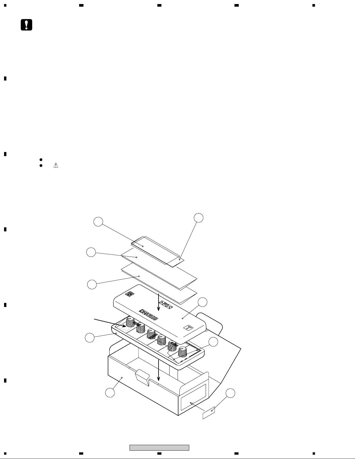
1. EXPLODED VIEWS AND PARTS LIST
OTES:
1.1 PACKING
C
(PACKING CASE)
D
Parts marked by "NSP" are generally unavailable because they are not in our Master Spare Parts List.
The mark found on some component parts indicates the importance of the safety factor of the part.
Therefore, when replacing, be sure to use parts of identical designation.
5
Warranty Card
(For JAPAN)
7
INSTRUCTION MANUAL
11
CORRECTION SHEET(J)
Rotary Volume Kit
6
Warranty Card
(For NORTH AMERICA)
3
E
F
2
1234
4
9
DJC-1000RV
2
10
Page 3

1
12
PACKAGING TAPE
PACKAGING TAPE
ROTALY VOLUME KIT
(PACKING CASE)
* LABEL PUT UP
STAMP UNDER
DESTINATION PLACE SYMBOL
234
A
B
•
Mark No. Description Part No.
NSP 5 Warranty Card (Japan) DRY1235
Packing Parts
1 • • • •
2 Mirror Mat Sheet DHL1147
3 Top Pad DHA1689
4 Bottom Pad DHA1688
C
D
E
NSP 6 Warranty Card (North America) ARY7043
NSP 11 Correction Sheet(J) DRM1266
DJC-1000RV
1
2
7 Instruction Manual DRC1262
8 • • • •
9 Packing Case DHG2551
10 Label VRW1629
12 Master Carton DHG2552
3
F
3
4
Page 4

1
1.2 EXTERIOR SECTION
A
23
4
(Front)
B
(Back)
4
C
4
6
6
6
6
6
6
7
1
8
1
1
7
4
(Back)
5
D
9
E
5
3
2
3
2
Yellow
3
2
White
5
7
Exterior Parts
•
Mark No. Description Part No.
1 Rotary Volume DCS1088
2 Connector Ass’y (W) DKP3738
3 Connector Ass’y (Y) DKP3739
4 Backed Mount DEC2171
5 Binder(SKB-90BK) ZCA-SKB90BK
6 VR Knob DAA1165
7 CHA Panel DAH2391
8 Nut M7 DBN1011
9 CE Mark Label (UP) RRW1221
F
4
1234
DJC-1000RV
Page 5
1
234
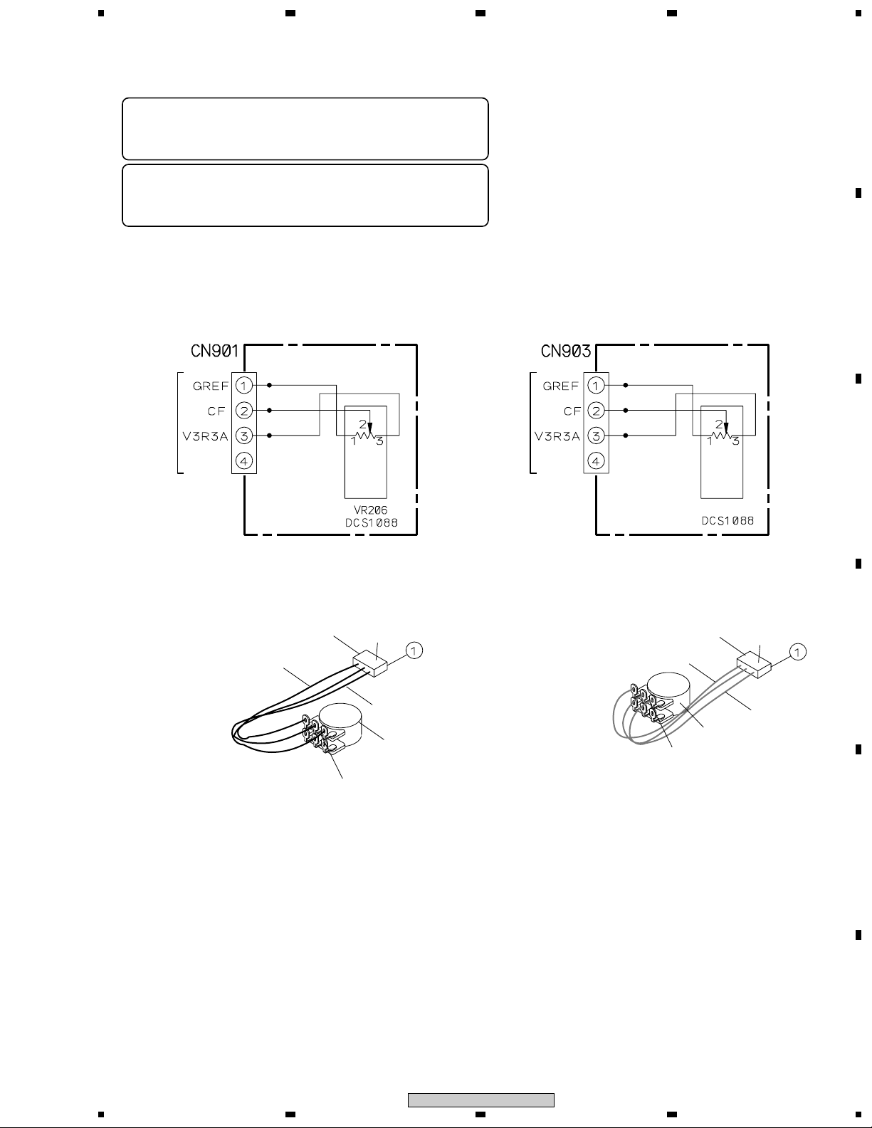
2. SCHEMATIC DIAGRAM
Note: Although the ref. numbers for the CH1/CH3/CH5 FADER Assys
are different, they are identical, and their functions in the circuitry are
the same. You can connect to either of them.
Note: Although the ref. numbers for the CH2/CH4/CH6 FADER Assys
are different, they are identical, and their functions in the circuitry are
the same. You can connect to either of them.
CH1/CH3/CH5 FADER ASSY
CN4504
CH2/CH4/CH6 FADER ASSY
CN4502
A
B
C
VR205
Connector Ass'y (W)
Gray
1
Solder
White
White
Rotary VR
Connector Ass'y (Y)
Gray
Rotary VR
1
Solder
Yellow
D
White
E
F
DJC-1000RV
1
2
3
4
5
Page 6

1
3. DISASSEMBLY
A
23
4
WARNING
Do not attempt to install this kit by your-self!
This kit requires professional expertise and must
be installed by a specially trained technician.
For details, inquire at your nearest authorized Pioneer service center. (Consult your retail dealer for
more information regarding authorized
B
Pioneerservice centers.)
NOTE:
Installation of this kit requires specialized professional
training and expertise. Consult your nearest authorized Pioneer service center for installation (installa-
tion fee must be paid by user).
Attempting to install this kit by yourself can be very
dangerous, and may result not only in damage to the
unit, but fire or electrical shock. Pioneer can accept
no liability for injuries or damages resulting from in-
stallations or modifications performed by
the cus-tomer.
To the Installing Service Personnel
Install this panel unit as depicted in the
accompanying illustrations and instructions.
• Before beginning work, be sure to disconnect
the power cord from its supply outlet.
C
3. Connect the cable connectors of
the faderunit (6).
ì
Insert the connectors securely,taking care
toconnect them in the proper order.
1. Remove the four screws at the corners ofthe
fader panel, and remove the panel.
D
4. Place the fader panel in its proper locationand
fasten using the four corner screws.
ì
Take care not to pinch the wiring between
thepanel and other parts when replacing
the faderpanel.
2. Disconnect the cable connectors (6).
E
ì
Store the removed fader panel in the packingbox
F
for this kit.
6
1234
DJC-1000RV
 Loading...