

Page 1
English
MANUEL D’INSTALLATION
Español
DEH-P88RS
This product conforms to new cord colors.
Los colores de los cables de este producto se conforman con un nuevo código de colores.
Dieses Produkt entspricht den neuen Kabelfarben.
Le code de couleur des câbles utilisé pour ce produit est
nouveau.
Questo prodotto è conforme ai nuovi codici colori.
De kleuren van de snoeren van dit toestel zijn gewijzigd.
чÌÌÓ ÛÒÚÓÈÒÚ‚Ó ÒÓÓÚ‚ÂÚÒÚ‚ÛÂÚ ÌÓ‚˚Ï
Ú·ӂ‡ÌËflÏ Í ˆ‚ÂÚÛ ÔÓ‚Ó‰Ó‚.
Deutsch
Français
Italiano
Nederlands
PyТТНЛИ
INSTALLATION MANUAL
Page 2

Contents
Connecting the Units
Connecting the Units ................................ 1
Power cable connection diagram ...................... 3
Connection diagram for standard mode
with internal amp ........................................5
Connection diagram for standard mode
without internal amp ..................................7
Connection diagram for 3-way network mode
with internal amp ........................................9
Connection diagram for 3-way network mode
without internal amp ................................11
Installation ................................................ 13
DIN Front/Rear-mount .................................... 13
DIN Front-mount ............................................ 13
DIN Rear-mount .............................................. 14
Switching the DSP setting mode ......................14
Note:
• This unit is for vehicles with a 12-volt battery
and negative grounding. Before installing it in a
recreational vehicle, truck, or bus, check the battery voltage.
• To avoid shorts in the electrical system, be sure
to disconnect the ≠ battery cable before beginning installation.
• Refer to the owner’s manual for details on connecting the power amp and other units, then
make connections correctly.
• Secure the wiring with cable clamps or adhesive
tape. To protect the wiring, wrap adhesive tape
around them where they lie against metal parts.
• Route and secure all wiring so it cannot touch
any moving parts, such as the gear shift, handbrake and seat rails. Do not route wiring in
places that get hot, such as near the heater outlet.
If the insulation of the wiring melts or gets torn,
there is a danger of the wiring short-circuiting to
the vehicle body.
• Don’t pass the yellow lead through a hole into
the engine compartment to connect to the battery. This will damage the lead insulation and
cause a very dangerous short.
• Do not shorten any leads. If you do, the protection circuit may fail to work when it should.
• Never feed power to other equipment by cutting
the insulation of the power supply lead of the
unit and tapping into the lead. The current capacity of the lead will be exceeded, causing overheating.
• When replacing fuse, be sure to only use a fuse
of the rating prescribed on the fuse holder.
• Since a unique BPTL circuit is employed, never
wire so the speaker leads are directly grounded
or the left and right ≠ speaker leads are common.
• If the RCA pin jack on the unit will not be used,
do not remove the caps attached to the end of the
connector.
• Speakers connected to this unit must be highpower with minimum rating of 50 W and impedance of 4 to 8 ohms. Connecting speakers with
output and/or impedance values other than those
noted here may result in the speakers
catching fire, emitting smoke or becoming damaged.
• When connecting tweeters, please confirm the
tweeter’s usable frequency range. When you set
the cut-off frequency, set higher than the lowest
usable frequency of the tweeter.
1
Page 3
• Auto TA uses higher range than 10 kHz for measurement. Therefore, using the tweeter that cannot reproduce 10 kHz frequency range may damage the tweeter. When Auto TA&EQ is operated,
be sure to set the appropriate cut-off frequency.
Also, use the tweeter that can reproduce 10 kHz
at the lowest usable frequency.
• When this product’s source is switched ON, a
control signal is output through the blue/white
lead. Connect to an external power amp’s system
remote control or the car’s Auto-antenna relay
control terminal (max. 300 mA 12 V DC). If the
car features a glass antenna, connect to the antenna booster power supply terminal.
• When an external power amp is being used with
this system, be sure not to connect the blue/white
lead to the amp’s power terminal. Likewise, do
not connect the blue/white lead to the power terminal of the auto-antenna. Such connection could
cause excessive current drain and malfunction.
• To avoid a short-circuit, cover the disconnected
lead with insulating tape. Insulate the unused
speaker leads without fail. There is a possibility
of a short-circuit if the leads are not insulated.
• To prevent incorrect connection, the input side of
the IP-BUS connector is blue, and the output side
is black. Connect the connectors of the same colors correctly.
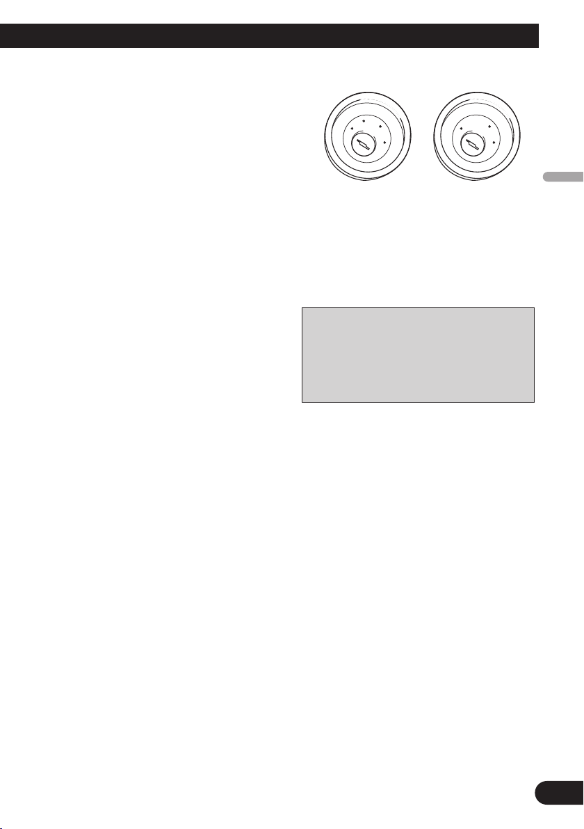
• If this unit is installed in a vehicle that does not
have an ACC (accessory) position on the ignition
switch, the red lead of the unit should be connected to a terminal coupled with ignition switch
ON/OFF operations. If this is not done, the vehicle battery may be drained when you are away
from the vehicle for several hours.
English
• Cords for this product and those for other
products may be different colors even if they
have the same function. When connecting this
product to another product, refer to the supplied manuals of both products and connect
cords that have the same function.
Español
Deutsch
Français
Italiano
C
C
A
O
F
N
F
O
S
T
A
R
T
O
F
N
F
O
S
T
A
R
T
No ACC positionACC position
• The black lead is ground. Please ground this lead
separately from the ground of high-current products such as power amps.
If you ground the products together and the
ground becomes detached, there is a risk of damage to the products or fire.
Nederlands
2
Page 4

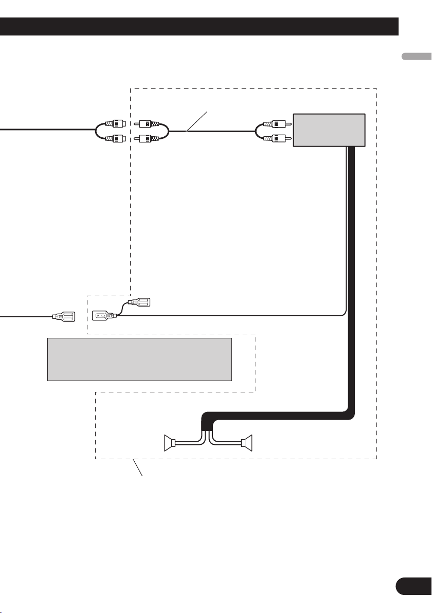
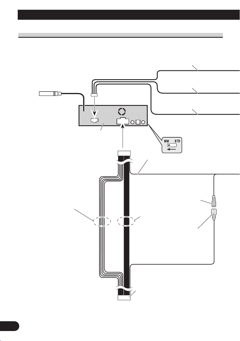
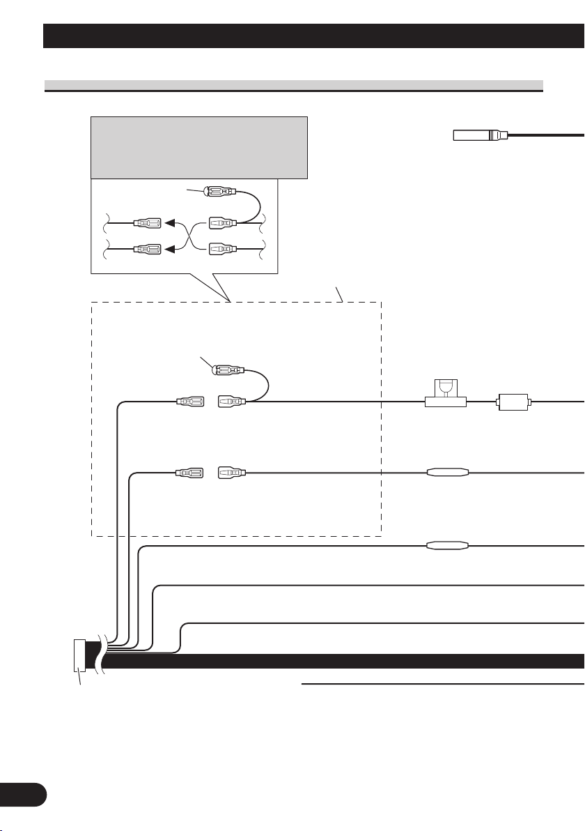
Connecting the Units
Fuse resistor
1*
2*
4*
3*
5*
Fuse holder
(10 A)
ISO connector
Note:
In some vehicles, the ISO connector may be
divided into two. In this case, be sure to connect
to both connectors.
Yellow/black
If you use an equipment with Mute function, wire
this lead to the Audio Mute lead on that equipment.
If not, keep the Audio Mute lead free of any
connections.
Black (ground)
To vehicle (metal) body.
Orange/white
To lighting switch terminal.
Red (4*)
To electric terminal controlled by
ignition switch (12 V DC)
ON/OFF.
Yellow (2*)
To terminal always supplied
with power regardless of
ignition switch position.
Red (5*)
Accessory
(or back-up)
Yellow (3*)
Back-up
(or accessory)
Cap (1*)
When not using this terminal, do
not remove the cap.
Note:
Depending on the kind of vehicle, the function
of 3* and 5* may be different. In this case, be
sure to connect 2* to 5* and 4* to 3*.
Connect leads of the same
color to each other.
Antenna jack
Fuse resistor
15 cm
Power cable connection diagram
3
Page 5

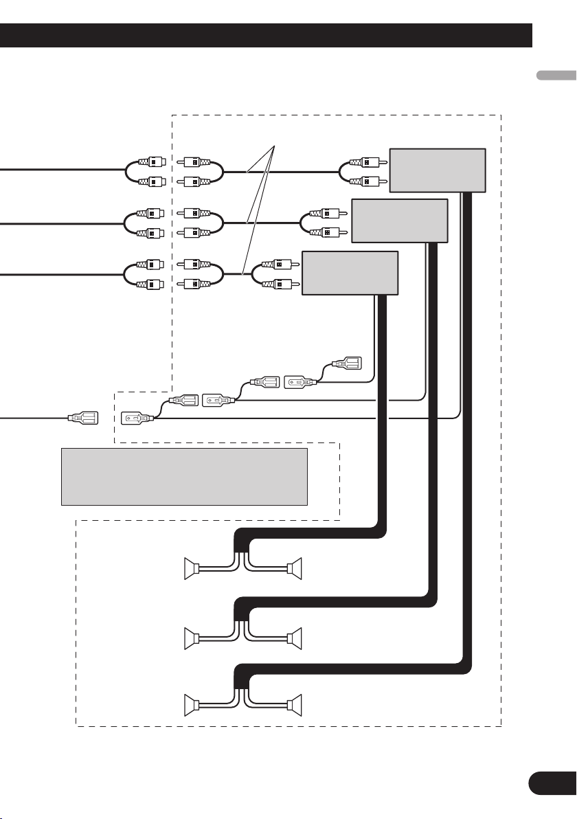
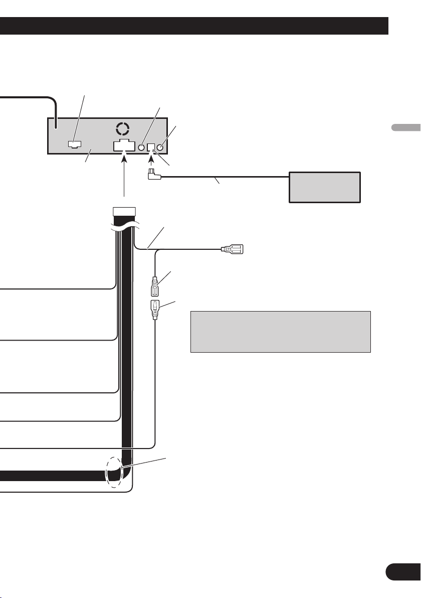
Speaker leads
(For more details, refer to page 5 to 12.)
White : Front left + or Middle range left +
White/black : Front left ≠ or Middle range left ≠
Gray : Front right + or Middle range right +
Gray/black : Front right ≠ or Middle range right ≠
Green : Rear left + or High range left +
Green/black : Rear left ≠ or High range left ≠
Violet : Rear right + or High range right +
Violet/black : Rear right ≠ or High range right ≠
Blue/white (6*)
Blue/white (7*)
ToAuto-antenna relay control terminal
(max. 300 mA 12 V DC).
Blue/white
To system control terminal of the power
amp (max. 300 mA 12 V DC).
This product
Jack for the Wired Remote ControlAdaptors
Please see the Instruction Manual for the
Wired Remote Control Adaptors (sold separately).
The pin position of the ISO connector will differ
depends on the type of vehicle. Connect 6* and 7*
when Pin 5 is an antenna control type. In another type
of vehicle, never connect 6* and 7*.
IP-BUS cable
Multi-CD player
(sold separately)
RCA cable connector
(Refer to page 5 to 12)
AUX input jack
IP-BUS input (Blue)
English
Español
Deutsch
Français
Italiano
Nederlands
4
Page 6

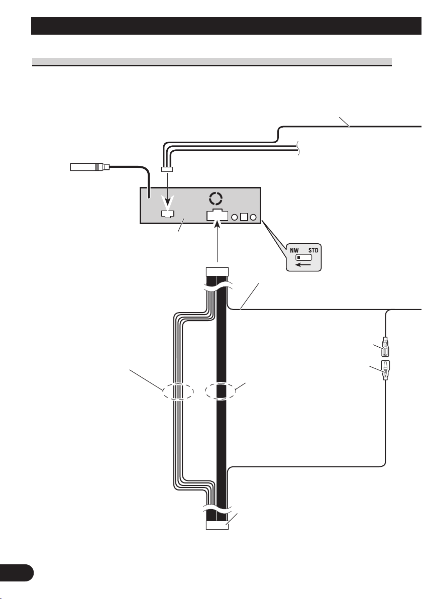
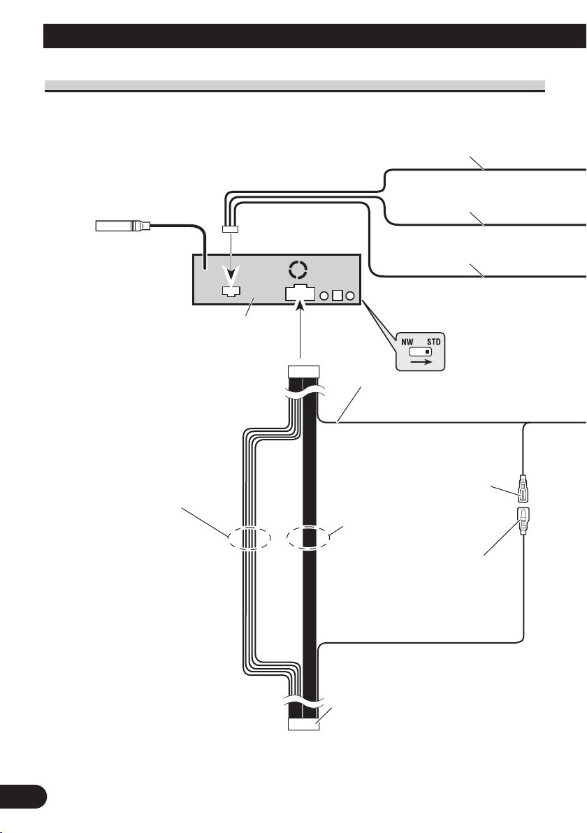
Connecting the Units
Antenna jack
DSP switch
Switch the DSP switch as
illustration below.
ISO connector
Note:
In some vehicles, the ISO connector
may be divided into two. In this case,
be sure to connect to both connectors.
Blue/white (6*)
Blue/white (7*)
To Auto-antenna relay control
terminal (max. 300 mA 12 V DC).
Blue/white
To system control terminal of the power
amp (max. 300 mA 12 V DC).
This product
Power cable
(For details, refer to page 3 to 4.)
Speaker leads
White : Front left +
White/black : Front left ≠
Gray : Front right +
Gray/black : Front right ≠
Green : Rear left +
Green/black : Rear left ≠
Violet : Rear right +
Violet/black : Rear right ≠
30 cm
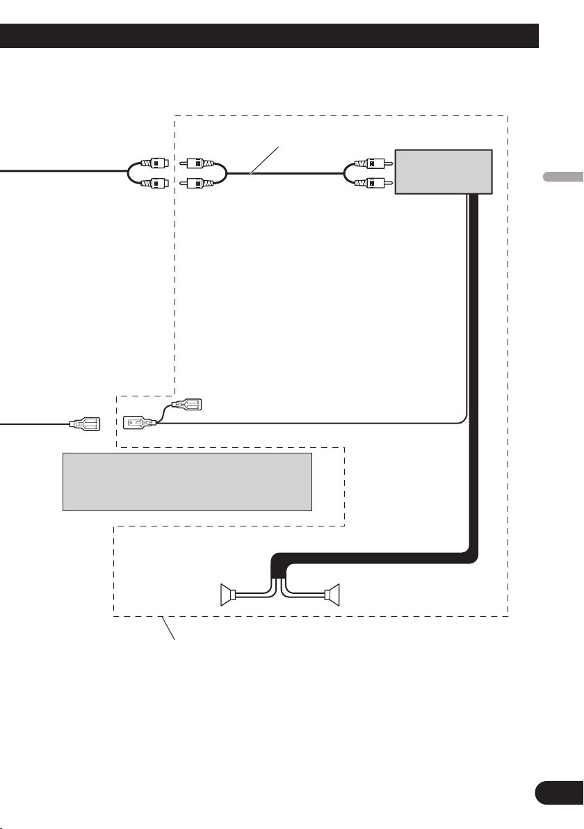
Connection diagram for standard mode with internal amp
5
Page 7
English
Subwoofer output
(LOW/SUBWOOFER
OUTPUT)
+
≠
+
≠
Subwoofer
Subwoofer
System remote control
Connecting cords with RCA pin
plugs (sold separately)
The pin position of the ISO connector will differ
depends on the type of vehicle. Connect 6* and 7*
when Pin 5 is an antenna control type. In another type
of vehicle, never connect 6* and 7*.
Power amp
(sold separately)
Perform this connection when using the optional amplifier.
Español
Deutsch
Français
Italiano
Nederlands
6
Page 8

Connecting the Units
Power cable
(For details, refer to page 3 to 4.)
Blue/white (7*)
To Auto-antenna relay control
terminal (max. 300 mA 12 V DC).
Blue/white
To system control terminal of the power
amp (max. 300 mA 12 V DC).
Antenna jack
DSP switch
Switch the DSP switch as
illustration below.
ISO connector
Note:
In some vehicles, the ISO connector
may be divided into two. In this case,
be sure to connect to both connectors.
This product
Blue/white (6*)
Speaker leads
Not used.
15 cm
30 cm
15 cm
Connection diagram for standard mode without internal amp
Note:
• If using this system, we recommend that this unit’s internal amp is turned off.
For more details, refer to operation manual.
7
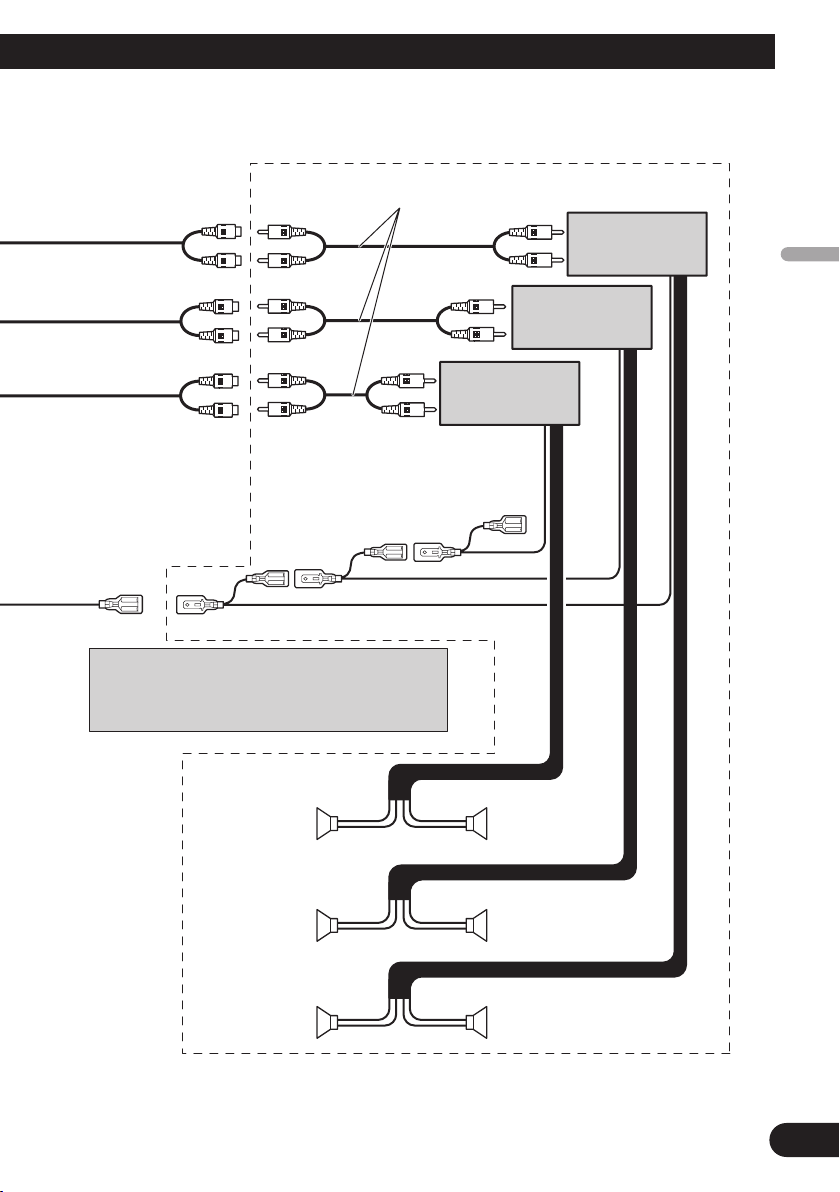
Page 9

English
Left
Right
Front output
(MID/FRONT OUTPUT)
Rear output
(HIGH/REAR OUTPUT)
Subwoofer output
(LOW/SUBWOOFER
OUTPUT)
+
≠
+
≠
+
≠
+
≠
+
≠
+
≠
Subwoofer
Front speaker
Rear speaker
Subwoofer
Front speaker
Rear speaker
System remote control
Power amp
(sold separately)
Connecting cords with RCA pin
plugs (sold separately)
The pin position of the ISO connector will differ
depends on the type of vehicle. Connect 6* and 7*
when Pin 5 is an antenna control type. In another type
of vehicle, never connect 6* and 7*.
Power amp
(sold separately)
Power amp
(sold separately)
Español
Deutsch
Français
Italiano
Nederlands
8
Page 10
Connecting the Units
Antenna jack
DSP switch
Switch the DSP switch as
illustration below.
ISO connector
Note:
In some vehicles, the ISO connector
may be divided into two. In this case,
be sure to connect to both connectors.
Blue/white
To system control terminal of the power
amp (max. 300 mA 12 V DC).
This product
Power cable
(For details, refer to page 3 to 4.)
Speaker leads
White : Middle range left +
White/black : Middle range left ≠
Gray : Middle range right +
Gray/black : Middle range right ≠
Green : High range left +
Green/black : High range left ≠
Violet : High range right +
Violet/black : High range right ≠
Blue/white (6*)
Blue/white (7*)
To Auto-antenna relay control
terminal (max. 300 mA 12 V DC).
30 cm
Connection diagram for 3-way network mode with internal amp
9
Page 11

English
Low range output
(LOW/SUBWOOFER
OUTPUT)
+
≠
+
≠
Low range speaker
System remote control
Connecting cords with RCA pin
plugs (sold separately)
The pin position of the ISO connector will differ
depends on the type of vehicle. Connect 6* and 7*
when Pin 5 is an antenna control type. In another type
of vehicle, never connect 6* and 7*.
Power amp
(sold separately)
Low range speaker
Left
Right
Perform this connection when using the optional amplifier.
Español
Deutsch
Français
Italiano
Nederlands
10
Page 12
Connecting the Units
Power cable
(For details, refer to page 3 to 4.)
Blue/white (7*)
To Auto-antenna relay control
terminal (max. 300 mA 12 V DC).
Blue/white
To system control terminal of the power
amp (max. 300 mA 12 V DC).
Antenna jack
DSP switch
Switch the DSP switch as
illustration below.
ISO connector
Note:
In some vehicles, the ISO connector
may be divided into two. In this case,
be sure to connect to both connectors.
This product
Blue/white (6*)
Speaker leads
Not used.
15 cm
30 cm
15 cm
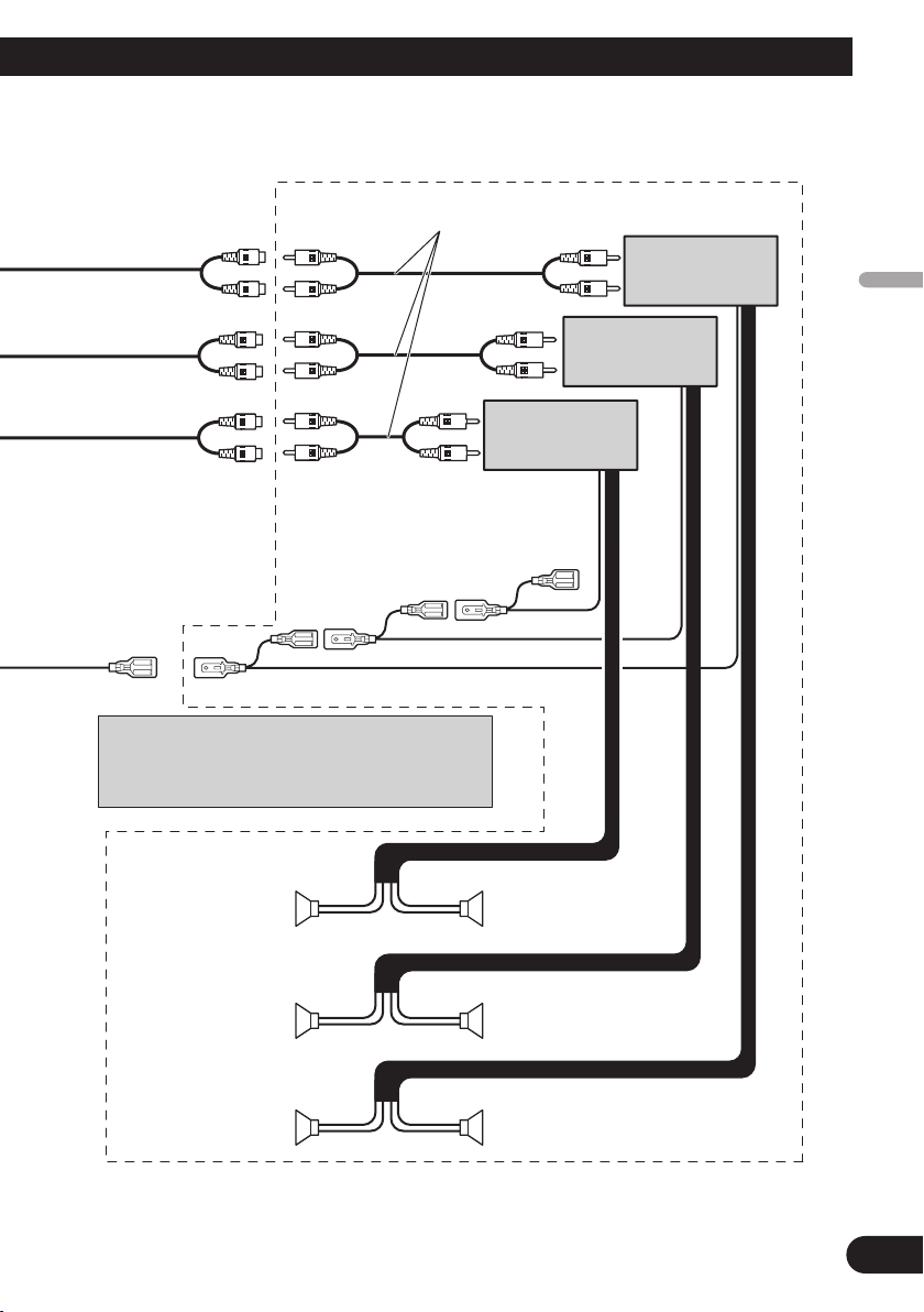
Connection diagram for 3-way network mode without internal amp
Note:
• If using this system, we recommend that this unit’s internal amp is turned off.
For more details, refer to operation manual.
11
Page 13
English
Left
Right
Middle range output
(MID/FRONT OUTPUT)
High range output
(HIGH/REAR OUTPUT)
Low range output
(LOW/SUBWOOFER
OUTPUT)
+
≠
+
≠
+
≠
+
≠
+
≠
+
≠
Low range speaker
High range speaker
Middle range speaker
Low range speaker
High range speaker
Middle range speaker
System remote control
Power amp
(sold separately)
Connecting cords with RCA pin
plugs (sold separately)
The pin position of the ISO connector will differ
depends on the type of vehicle. Connect 6* and 7*
when Pin 5 is an antenna control type. In another type
of vehicle, never connect 6* and 7*.
Power amp
(sold separately)
Power amp
(sold separately)
Español
Deutsch
Français
Italiano
Nederlands
12
Page 14
Installation
Note:
• Before making a final installation of the unit, temporarily connect the wiring to confirm that the
connections are correct and the system works
properly.
• Use only the parts included with the unit to ensure
proper installation. The use of unauthorized parts
can cause malfunctions.
• Consult with your nearest dealer if installation
requires the drilling of holes or other modifications of the vehicle.
• Install the unit where it does not get in the driver’s way and cannot injure the passenger if there
is a sudden stop, like an emergency stop.
• The semiconductor laser will be damaged if it
overheats, so don’t install the unit anywhere hot
— for instance, near a heater outlet.
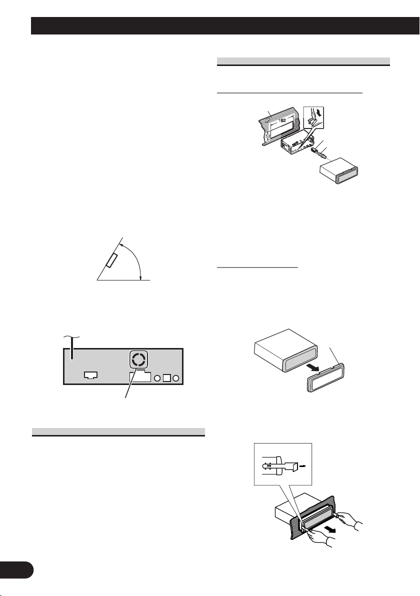
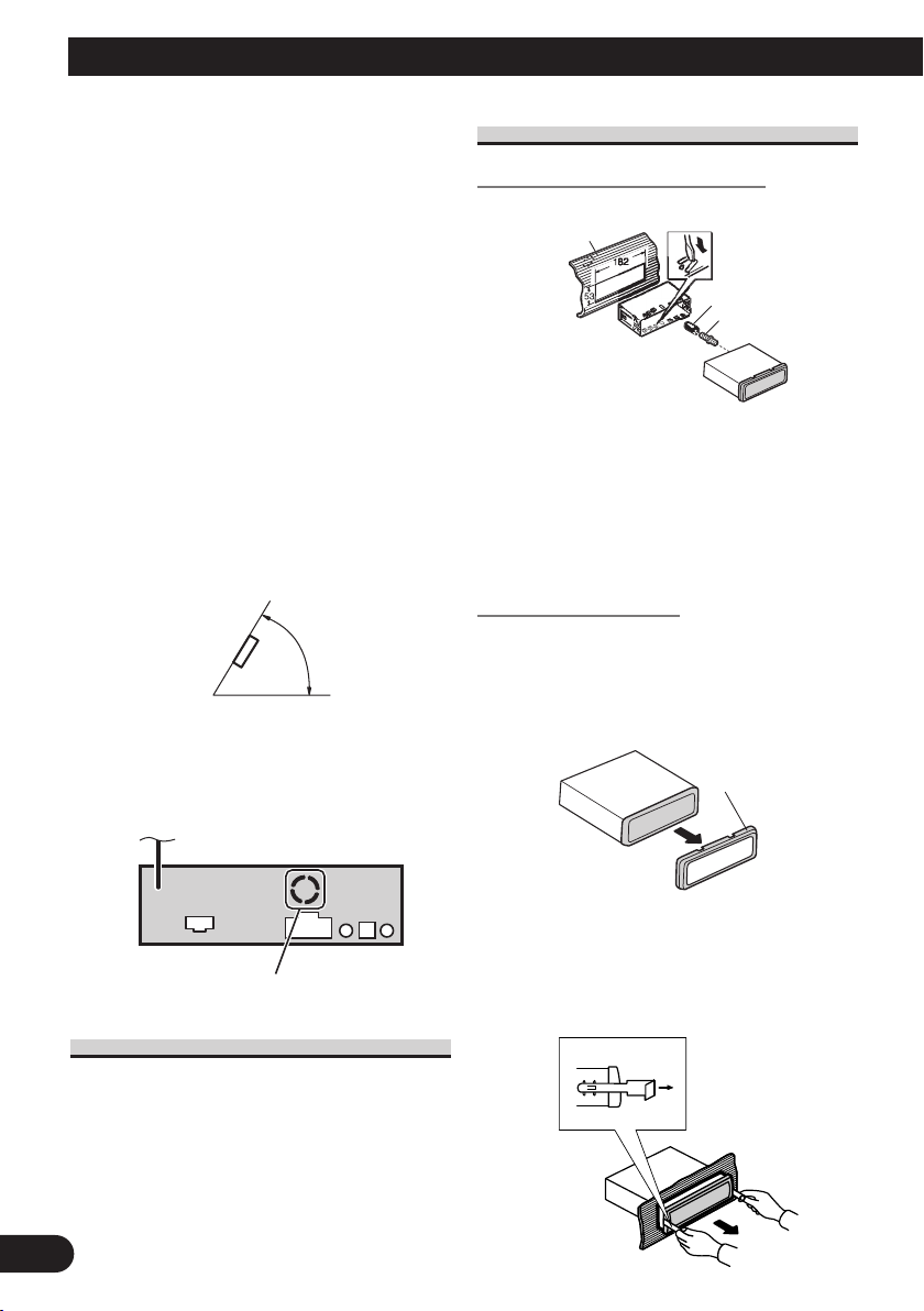
• If installation angle exceeds 60° from horizontal,
the unit might not give its optimum performance.
60°
• The cords must not cover up the area shown in the
figure below. This is necessary to allow the
amplifres to radiate freely.
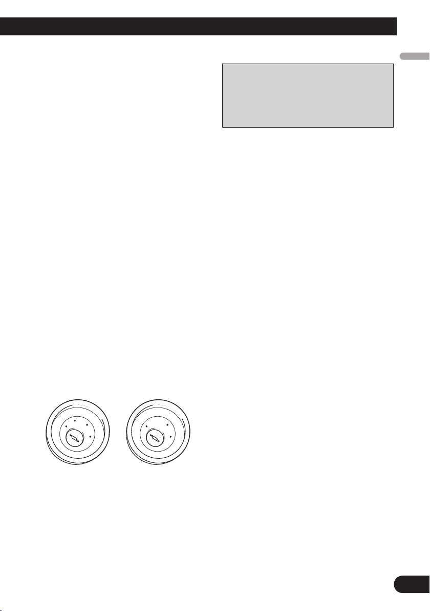
DIN Front-mount
Installation with the rubber bush
Dashboard
After inserting the holder into the dashboard, then
select the appropriate tabs according to the thickness of the dashboard material and bend them.
(Install as firmly as possible using the top and
bottom tabs. To secure, bend the tabs 90 degrees.)
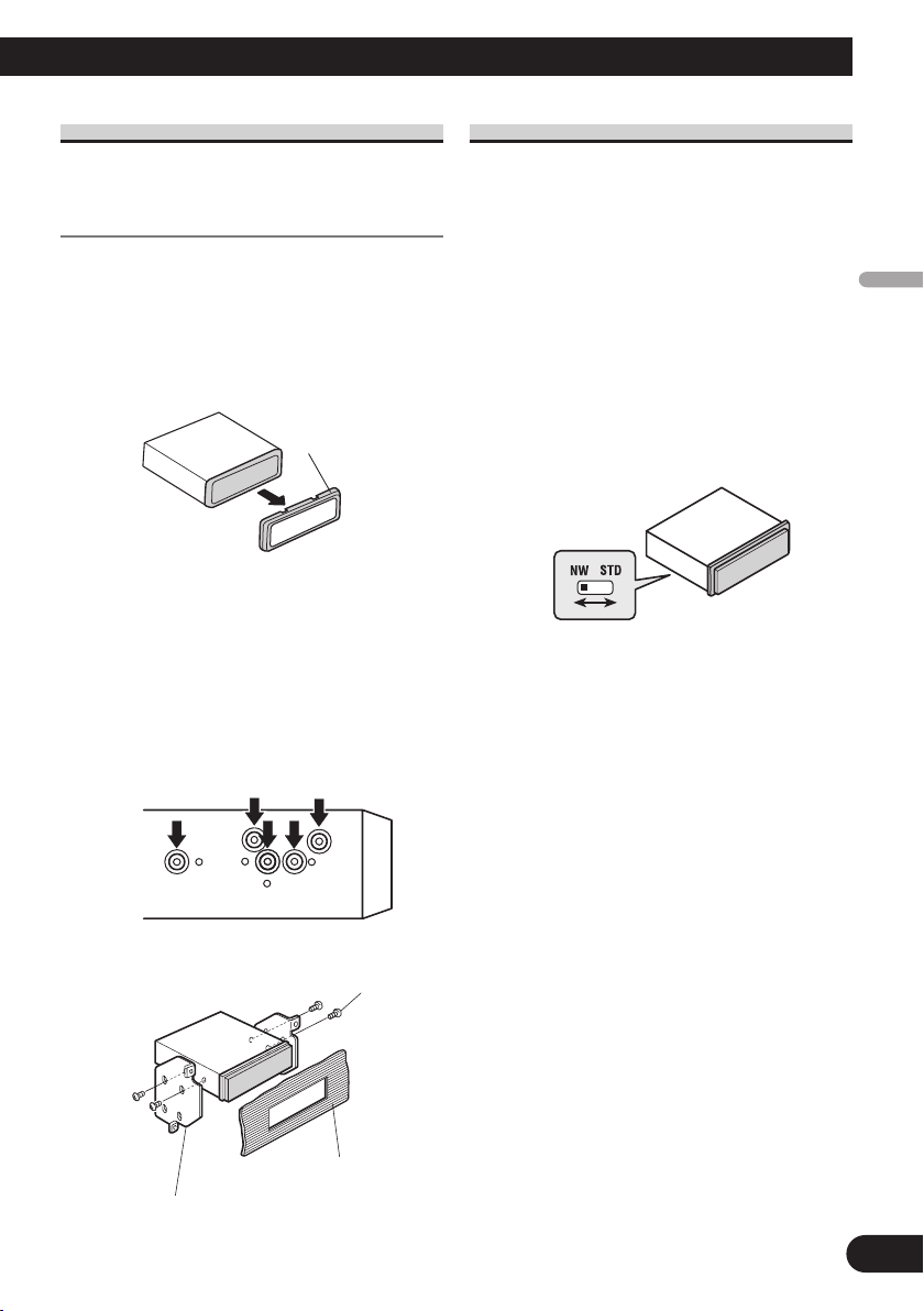
Removing the Unit
To remove the frame, extend top and bottom of
the frame outwards in order to unlock it. (When
reattaching the frame, point the side with a groove
downwards and attach it.)
• It becomes easy to remove the frame if the front
panel is released.
Holder
Rubber bush
Screw
Frame
Do not close this area.
DIN Front/Rear-mount
This unit can be properly installed
either from “Front” (conventional DIN
Front-mount) or “Rear” (DIN Rearmount installation, utilizing threaded
screw holes at the sides of unit chassis).
For details, refer to the following illustrated installation methods.
13
Insert the supplied extraction keys into the unit, as
shown in the figure, until they click into place.
Keeping the keys pressed against the sides of the
unit, pull the unit out.
Page 15
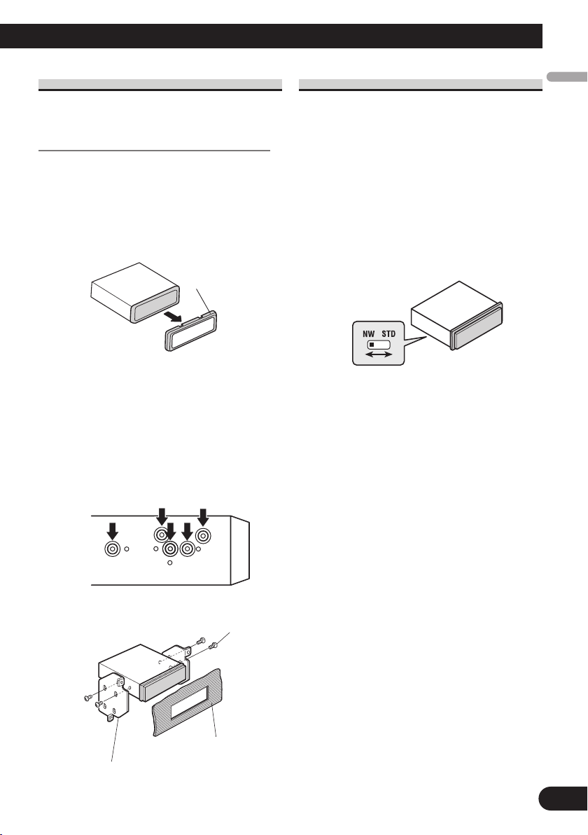
DIN Rear-mount
Installation using the screw holes
on the side of the unit
1. Remove the frame.
To remove the frame, extend top and bottom of
the frame outwards in order to unlock it. (When
reattaching the frame, point the side with a groove
downwards and attach it.)
• It becomes easy to remove the frame if the front
panel is released.
Frame
Switching the DSP setting mode
This product features two operation modes:
the 3-way network mode (NW) and the
standard mode (STD). You can switch
between modes as desired. Initially, the
DSP setting is set to the standard mode
(STD).
• After switching, reset the microprocessor. (Refer
to operation manual.)
• Use a thin standard tip screwdriver to switch the DSP switch on the
side of this product.
English
Español
Deutsch
2. Fastening the unit to the factory
radio mounting bracket.
Select a position where the screw holes of the
bracket and the screw holes of the head unit
become aligned (are fitted), and tighten the screws
at 2 places on each side. Use either truss screws (5
× 8 mm) or flush surface screws (5 × 9 mm),
depending on the shape of the screw holes in the
bracket.
Screw
Dashboard or Console
Factory radio mounting bracket
Français
Italiano
Nederlands
14
Page 16

Contenido
Conexión de las unidades
Conexión de las unidades ........................ 1
Diagrama de conexión del cable de
alimentación ................................................3
Diagrama de conexión para modo estándar
con amplificador interno ..............................5
Diagrama de conexión para modo estándar
sin amplificador interno ..............................7
Diagrama de conexión para modo de red
de 3 vías con amplificador interno ..............9
Diagrama de conexión para modo de red
de 3 vías sin amplificador interno ..............11
Instalación ................................................ 13
Montaje delantero/trasero DIN ........................ 13
Montaje delantero DIN .................................... 13
Montaje trasero DIN ........................................ 14
Conmutación del modo de ajuste de DSP ...... 14
Nota:
• Esta unidad es para vehículos con batería de 12
voltios y con conexión a tierra. Antes de instalar
la unidad en un vehículo recreativo, camioneta, o
autobús, revise el voltaje de la batería.
• Para evitar cortocircuitos en el sistema eléctrico,
asegúrese de desconectar el cable de la batería ≠
antes de comenzar con la instalación.
• Consulte con el manual del usuario para los
detalles sobre la conexión de la alimentación de
amperios y de otras unidades, luego haga las
conexiones correctamente.
• Asegure el cableado con abrazaderas de cables o
con cinta adhesiva. Para proteger el cableado,
envuélvalo con cinta adhesiva donde éstos se
apoyan sobre las piezas de metal.
• Coloque y asegure todo el cableado de tal
manera que no toque las piezas en movimiento,
tal como la palanca de cambio de velocidades, el
freno de mano, y los pasamanos de los asientos.
No coloque el cableado en lugares que se
calientan, tal como cerca de la salida de un
calefactor. Si el material aislante del cableado se
derritiera o se gastara, habrá el peligro de un
cortocircuito del cableado a la carrocería del
vehículo.
• No pase el conductor amarillo a través de un
orificio en el compartimiento del motor para
conectar a la batería. Esto dañará el material
aislante del conductor y causará un cortocircuito
peligroso.
• No acorte ningún conductor. Si lo hiciera, la
protección del circuito podría fallar al funcionar
cuando debería.
• Nunca alimente energía a otros equipos cortando
el aislamiento del conductor de alimentación
provista de la unidad y haciendo un empalme
con el conductor. La capacidad de corriente del
conductor se excederá, causando el
recalentamiento.
• Cuando reemplace el fusible, asegúrese de
utilizar solamente un fusible del ratio
especificado en el portafusible.
• Ya que se emplea un circuito único BPTL, nunca
coloque los cables de manera que los
conductores del altavoz estén directamente en
conexión a tierra o que el altavoz izquierdo y
derecho ≠ sean comunes.
• Si la toma de clavija RCA en la unidad no se
usa, retire las tapas fijadas al extremo del
conector.
1
Page 17
• Los altavoces conectados a esta unidad deben ser
del tipo de alta potencia con un régimen mínimo
de 50 W y una impedancia de 4 a 8 ohmios. La
conexión de altavoces con valores de impedancia
y/o de salida diferentes a los anotados aquí
podrían causar fuego, emisión de humo o daños a
los altavoces.
• Cuando conecte tweeters, compruebe el rango de
frecuencia utilizable del tweeter. Cuando ajuste la
frecuencia de corte, ajústela más alta que la
frecuencia utilizable más baja del tweeter.
• La función Auto TA utiliza un rango más alto
que 10 kHz para la medición. Por lo tanto, el uso
de un tweeter que no puede reproducir el rango
de frecuencia de 10 kHz puede dañar el tweeter.
Cuando opere la función Auto TA&EQ,
asegúrese de ajustar la frecuencia de corte
apropiada. De la misma forma, utilice un tweeter
que pueda reproducir 10 kHz en la frecuencia
utilizable más baja.
• Cuando se conecta la fuente de este producto, una
señal de control se emite a través del conductor
azul/blanco. Conecte al control remoto de sistema
de un amplificador de potencia externo o al
terminal de controle de relé de antena automática
del vehículo (máx. 300 mA 12 V CC). Si el
vehículo tiene una antena en vidrio, conecte al
terminal de suministro de energía de la antena.
• Cuando se está utilizando un amperio de potencia
externa con este sistema, asegúrese de no
conectar el conductor azul/blanco al terminal de
potencia de amperios. Asimismo, no conecte el
conductor azul/blanco al terminal de potencia de
la auto-antena. Tal conexión podría causar la fuga
de corriente excesiva y causar fallos de
funcionamiento.
• Para evitar cortocircuitos, cubra o conductor
desconectado con cinta aislada. Aísle los
conductores de altavoz no usados sin falta. Hay la
posibilidad de cortocircuito si no se aíslan los
conductores.
• Para evitar la conexión incorrecta, el lado de
entrada del conector IP-BUS es azul, y el lado de
salida es negro. Conecte los conectores del
mismo color correctamente.
• Si se instala esta unidad en un vehículo que no
tiene una posición ACC (accesorio) en el
interruptor de encendido, el conductor rojo de la
unidad deberá conectarse al terminal conectado
con las operaciones del interruptor de encendido
ON/OFF. Si no se hace esto, la batería del
vehículo podría drenarse cuando usted esté lejos
del vehículo por varias horas.
C
C
A
O
F
N
F
O
T
Posición ACC
S
T
A
R
No en la posición ACC
O
F
N
F
O
S
T
A
R
T
• El conductor negro es la masa. Conecte a masa
este conductor separadamente desde la masa de
los productos de alta corriente tal como los
amplificadores de potencia.
Si conecta juntos a masa los productos y la masa
se desconecta, se crea el riesgo de daños a los
productos o de incendios.
• Los cables para este producto y aquéllas para
otros productos pueden ser de colores
diferentes aun si tienen la misma función.
Cuando se conecta este producto a otro,
refiérase a los manuales de ambos productos y
conecte los cables que tienen la misma
función.
English
Español
Deutsch
Français
Italiano
Nederlands
2
Page 18
Conexión de las unidades
Resistencia de fusible
1*
2*
4*
3*
5*
Portafusible
(10 A)
Conector ISO
Nota:
En algunos vehículos, el conector ISO puede
estar dividido en dos partes. En este caso,
asegúrese de conectar a ambos conectores.
Amarillo/negro
Si se utiliza un equipo con función de silenciamiento,
conecte este conductor con el conductor de
silenciamiento de audio en tal equipo.
Si no, mantenga el enmudecimiento de audio libre de
cualquier conexión.
Negro (masa)
A la carrocería del vehículo
(parte metálica).
Anaranjado/blanco
Al terminal de interruptor de
iluminación.
Rojo (4*)
Al terminal de energía eléctrica
controlado por el interruptor de
encendido del vehículo (12 V CC)
ON/OFF.
Amarillo (2*)
Al terminal con suministro
constante de electricidad,
independientemente de la posición
del interruptor de encendido.
Rojo (5*)
Accesorio
(o reserva)
Amarillo (3*)
Reserva (o
accesorio)
Tapa (1*)
Cuando este terminal no se usa,
no retire la tapa.
Nota:
Dependiendo del tipo del vehículo, la función
de 3* y 5* puede ser diferente. En este caso,
asegúrese de conectar 2* a 5* y 4* a 3*.
Conecte los conductores del
mismo color uno a otro.
Jack para antena
Resistencia de fusible
15 cm
Diagrama de conexión del cable de alimentación
3
Page 19
Cables de altavoz
(Para los detalles, consulte la página 5 a 12.)
Blanco : Izquierdo delantero + o rango medio izquierdo +
Blanco/negro : Izquierdo delantero ≠ o rango medio izquierd ≠
Gris : Derecho delantero + o rango medio derecho +
Gris/negro : Derecho delantero ≠ rango medio derecho ≠
Verde : Izquierdo trasero + o rango alto izquierdo +
Verde/negro : Izquierdo trasero ≠ o rango alto izquierdo ≠
Violeta : Derecho trasero + o rango alto derecho +
Violeta/negro : Derecho trasero ≠ o rango alto derecho ≠
Azul/blanco (6*)
Azul/blanco (7*)
Al terminal de control de relé de antena
automática (máx. 300 mA 12 V CC).
Azul/blanco
Al terminal de control del sistema del
amplificador de potencia (máx. 300 mA
12 V CC).
Este producto
Toma para los adaptadores de control remoto inalámbrico
Consulte el manual de instrucciones para los adaptadores
de control remoto inalámbrico (vendidos separadamente).
La posición de los pinos del conector ISO difiere de
acuerdo al tipo de vehículo. Conecte 6* y 7* cuando
el pino 5 es un tipo de control de antena. En otros
tipos de vehículo, nunca conecte 6* y 7*.
Cable IP-BUS
Reproductor de
Multi-CD (en venta
por separado)
Conector de cable RCA
(Consulte la página 5 a 12.)
Toma de entrada AUX
Entrada IP-BUS (Azul)
English
Español
Deutsch
Français
Italiano
Nederlands
4
Page 20

Conexión de las unidades
Jack para antena
Conmutator de DSP
Conecte el conmutador de DSP
de acuerdo con la siguiente
ilustración.
Conector ISO
Nota:
En algunos vehículos, el conector ISO
puede estar dividido en dos partes. En
este caso, asegúrese de conectar a ambos
conectores.
Azul/blanco (6*)
Azul/blanco (7*)
Al terminal de control de relé de
antena automática (máx. 300 mA
12 V CC).
Azul/blanco
Al terminal de control del sistema del
amplificador de potencia (máx. 300 mA
12 V CC).
Este producto
Cable de alimentación
(Para los detalles, consulte
la página 3 a 4.)
Cables de altavoz
Blanco : Izquierdo delantero +
Blanco/negro : Izquierdo delantero ≠
Gris : Derecho delantero +
Gris/negro : Derecho delantero ≠
Verde : Izquierdo trasero +
Verde/negro : Izquierdo trasero ≠
Violeta : Derecho trasero +
Violeta/negro : Derecho trasero ≠
30 cm
Diagrama de conexión para modo estándar con amplificador interno
5
Page 21

Salida de altavoz de
graves secundario
(LOW/SUBWOOFER
OUTPUT)
+
≠
+
≠
Altavoz secundario
Altavoz secundario
Control remoto de sistema
Cables de conexión con clavijás
RCA (en venta por separado)
La posición de los pinos del conector ISO difiere de
acuerdo al tipo de vehículo. Conecte 6* y 7* cuando
el pino 5 es un tipo de control de antena. En otros
tipos de vehículo, nunca conecte 6* y 7*.
Amplificador de
potencia (en venta
por separado)
Lleve a cabo esta conexión cuando utilice el amplificador opcional.
English
Español
Deutsch
Français
Italiano
Nederlands
6
Page 22
Conexión de las unidades
Cable de alimentación
(Para los detalles, consulte
la página 3 a 4.)
Conector ISO
Nota:
En algunos vehículos, el conector ISO
puede estar dividido en dos partes. En
este caso, asegúrese de conectar a ambos
conectores.
Cables de altavoz
No se usa.
Jack para antena
Conmutator de DSP
Conecte el conmutador de DSP
de acuerdo con la siguiente
ilustración.
Azul/blanco (6*)
Azul/blanco (7*)
Al terminal de control de relé de
antena automática (máx. 300 mA
12 V CC).
Azul/blanco
Al terminal de control del sistema del
amplificador de potencia (máx. 300 mA
12 V CC).
Este producto
15 cm
30 cm
15 cm
Diagrama de conexión para modo estándar sin amplificador interno
Nota:
• Cuando utilice este sistema, se recomienda apagar el amplificador interno de esta unidad.
Para los detalles, consulte el manual de instrucciones.
7
Page 23
English
Izquierda
Derecha
Salida delantera
(MID/FRONT OUTPUT)
Salida trasera
(HIGH/REAR OUTPUT)
+
≠
+
≠
+
≠
+
≠
+
≠
+
≠
Altavoz delantero
Altavoz trasero
Altavoz delantero
Altavoz trasero
Altavoz secundario
Altavoz secundario
Control remoto de sistema
La posición de los pinos del conector ISO difiere de
acuerdo al tipo de vehículo. Conecte 6* y 7* cuando
el pino 5 es un tipo de control de antena. En otros
tipos de vehículo, nunca conecte 6* y 7*.
Salida de altavoz
de graves secundario
(LOW/SUBWOOFER
OUTPUT)
Cables de conexión con clavijás
RCA (en venta por separado)
Amplificador de
potencia (en venta
por separado)
Amplificador de
potencia (en venta
por separado)
Amplificador de
potencia (en venta
por separado)
Español
Deutsch
Français
Italiano
Nederlands
8
Page 24

Conexión de las unidades
Cable de alimentación
(Para los detalles, consulte
la página 3 a 4.)
Jack para antena
Conmutator de DSP
Conecte el conmutador de DSP
de acuerdo con la siguiente
ilustración.
Azul/blanco (6*)
Azul/blanco (7*)
Al terminal de control de relé de
antena automática (máx. 300 mA
12 V CC).
Azul/blanco
Al terminal de control del sistema del
amplificador de potencia (máx. 300 mA
12 V CC).
Este producto
Cables de altavoz
Blanco : Rango medio izquierdo +
Blanco/negro : Rango medio izquierdo ≠
Gris : Rango medio derecho +
Gris/negro : Rango medio derecho ≠
Verde : Rango alto izquierdo +
Verde/negro : Rango alto izquierdo ≠
Violeta : Rango alto derecho +
Violeta/negro : Rango alto derecho ≠
Conector ISO
Nota:
En algunos vehículos, el conector ISO
puede estar dividido en dos partes. En
este caso, asegúrese de conectar a ambos
conectores.
30 cm
Diagrama de conexión para modo de red de 3 vías con amplificador interno
9
Page 25
English
Salida de rango bajo
(LOW/SUBWOOFER
OUTPUT)
+
≠
+
≠
Altavoz de rango bajo
Altavoz de rango bajo
Cables de conexión con clavijás
RCA (en venta por separado)
Amplificador de
potencia (en venta
por separado)
Control remoto de sistema
La posición de los pinos del conector ISO difiere de
acuerdo al tipo de vehículo. Conecte 6* y 7* cuando
el pino 5 es un tipo de control de antena. En otros
tipos de vehículo, nunca conecte 6* y 7*.
Lleve a cabo esta conexión cuando utilice el amplificador opcional.
Izquierda
Derecha
Español
Deutsch
Français
Italiano
Nederlands
10
Page 26

Conexión de las unidades
Cable de alimentación
(Para los detalles, consulte
la página 3 a 4.)
Cables de altavoz
No se usa.
Jack para antena
Conmutator de DSP
Conecte el conmutador de DSP
de acuerdo con la siguiente
ilustración.
Azul/blanco (6*)
Azul/blanco (7*)
Al terminal de control de relé de
antena automática (máx. 300 mA
12 V CC).
Azul/blanco
Al terminal de control del sistema del
amplificador de potencia (máx. 300 mA
12 V CC).
Este producto
Conector ISO
Nota:
En algunos vehículos, el conector ISO
puede estar dividido en dos partes. En
este caso, asegúrese de conectar a ambos
conectores.
15 cm
30 cm
15 cm
Diagrama de conexión para modo de red de 3 vías sin amplificador interno
Nota:
• Cuando utilice este sistema, se recomienda apagar el amplificador interno de esta unidad.
Para los detalles, consulte el manual de instrucciones.
11
Page 27
English
Salida de rango medio
(MID/FRONT OUTPUT)
Salida de rango alto
(HIGH/REAR OUTPUT)
+
≠
+
≠
+
≠
+
≠
+
≠
+
≠
Altavoz de rango bajo
Altavoz de rango alto
Altavoz de rango medio
Altavoz de rango bajo
Altavoz de rango alto
Altavoz de rango medio
Control remoto de sistema
La posición de los pinos del conector ISO difiere de
acuerdo al tipo de vehículo. Conecte 6* y 7* cuando
el pino 5 es un tipo de control de antena. En otros
tipos de vehículo, nunca conecte 6* y 7*.
Salida de rango bajo
(LOW/SUBWOOFER
OUTPUT)
Cables de conexión con clavijás
RCA (en venta por separado)
Amplificador de
potencia (en venta
por separado)
Amplificador de
potencia (en venta
por separado)
Amplificador de
potencia (en venta
por separado)
Izquierda
Derecha
Español
Deutsch
Français
Italiano
Nederlands
12
Page 28
Instalación
Nota:
• Antes de finalmente instalar la unidad, conecte el
cableado temporalmente y compruebe que las
conexiones están correctas e que el sistema
funciona debidamente.
• Utilice sólo las piezas que se incluyen con esta
unidad para asegurar la instalación adecuada. El
uso de piezas no autorizadas podría causar fallos
de funcionamiento.
• Consulte con su distribuidor si la instalación
requiere del taladro de orificios u otras
modificaciones del vehículo.
• Instale la unidad donde no alcance el espacio del
conductor, y donde no pueda dañar a los pasajeros
si sucediera un paro repentino, como una
detención de emergencia.
• El semiconductor láser se dañará si se sobrecalienta, por eso no instale la unidad en un lugar
caliente – por ejemplo, cerca de la salida de un
calefactor.
• Si el ángulo de la instalación excede los 60° del
lado horizontal, la unidad podría no brindar su
óptimo funcionamiento.
60°
• Los cables no deben cubrir el área que se muestra
en la figura a continuación. Esto es necesario para
permitir la disipación de calor de los
amplificadores.
Montaje delantero DIN
Instalación con tope de goma
Tablero de
instrumentos
Después de insertar el soporte en la tabla de
mandos, luego seleccione las orejetas apropiadas
según el grosor del material de la tabla de mandos
y dóblelos.
(Instale lo más firme posible usando las lengüetas superior e inferior. Para fijar, doble las
lengüetas 90 grados.)
Quitado de la unidad
Para quitar el marco, extienda las partes superior e
inferior del marco hacia fuera para desbloquearlo.
(Cuando recoloque el marco, apunte el lado con
una ranura hacia abajo y fíjelo.)
• Se hace más fácil quitar el marco si se suelta el
panel delantero.
Soporte
Tope de goma
Tornillo
Marco
No cierre esta área.
Montaje delantero/trasero DIN
Esta unidad quede instalarse correstamente
de la “Delantera” (montaje delantero DIN
convenciona) o “Trasera” (montaje trasero
DIN, utilizando los tornillos roscados en los
constados del chasis de la unidad). Para
detalles, refiérase a los métodos de
instalación ilustrados abajo.
13
Inserte las herramientas de extracción suministradas en la unidad, como se indica en la figura,
hasta que se enganchen en su positión.
Tire de la unidad mientras mantiene las
herramientas presionadas contra los lados de la
unidad.
Page 29
Montaje trasero DIN
Conmutación del modo de ajuste de DSP
Instalación usando los agujeros para tornillos
ubicados en ambos costados de la unidad
1. Quite el marco.
Para quitar el marco, extienda las partes superior e
inferior del marco hacia fuera para desbloquearlo.
(Cuando recoloque el marco, apunte el lado con
una ranura hacia abajo y fíjelo.)
• Se hace más fácil quitar el marco si se suelta el
panel delantero.
Marco
• Después de la conexión, reinicialice el
• Utilice un destornillador de punta
Este producto brinda dos modos de
operación: el modo de red de 3 vías (NW) y
el modo estándar (STD). Podrá cambiar
entre los modos según se desee.
Inicialmente, el ajuste de DSP se encuentra
configurado en el modo estándar (STD).
microprocesador. (Refiérase al manual de
operación.)
delgada estándar para conectar el
conmutador de DSP en el lado de
este producto.
English
Español
Deutsch
2. Fijación de la unidad a la ménsula
de montaje existente.
Seleccione una posición en la que los orificios
para los tornillos del soporte y del de la unidad
principal queden alineados, y apriete los tornillos
en 2 lugares de un lado. Utilice ya sea los tornillos
de fijación (5 × 8 mm) o los tornillos a paño (5 × 9
mm), dependiendo de la forma de los orificios de
tornillo en la ménsula.
Tornillo
Tablero de instrumentos
o consola
Ménsula de montaje de radio existente
Français
Italiano
Nederlands
14
Page 30

Inhalt
Anschließen der Geräte
Anschließen der Geräte .......................... 1
Stromkabelanschlussschema ..............................3
Anschlussschema für Standardmodus
mit internem Verstärker ..............................5
Anschlussschema für Standardmodus
ohne internen Verstärker ..............................7
Anschlussschema für 3-Weg-Netzwerkmodus
mit internem Verstärker ..............................9
Anschlussschema für 3-Weg-Netzwerkmodus
ohne internen Verstärker ............................11
Einbau ........................................................ 13
DIN-Befestigung von vorne/hinten.................. 13
DIN-Vordermontage ...................................... 13
DIN-Rückmontage .......................................... 14
Umschalten des DSP-Einstellmodus ................14
Hinweis:
• Dieses Gerät ist für Fahrzeuge mit 12-V-Batterie
und negativer Erdung (Minuspol an Masse)
ausgelegt. Prüfen Sie vor dem Einbau in ein
Wohnmobil, einen Lastwagen oder Bus die
Batteriespannung.
• Um Kurzschlüsse im elektrischen System zu
verhindern, ist unbedingt vor dem Einbau das
Minus-Batteriekabel ≠ abzutrennen.
• Nehmen Sie die Anschlüsse gemäß den
Anweisungen zum Anschluss des
Leistungsverstärkers und anderer Geräte in der
Bedienungsanleitung vor.
• Sichern Sie die Leitungen mit Kabelklemmen
oder Klebeband. Zum Schutz der Leitungen
sollten sie an den Stellen, wo sie Metallteile
berühren, mit Klebeband umwickelt werden.
• Verlegen und sichern Sie alle Leitungen so, dass
sie keine beweglichen Teile wie die
Gangschaltung, die Handbremse und
Sitzschienen berühren. Die Leitungen dürfen
nicht an Stellen entlanggeführt werden, die heiß
werden, z.B. an einer Heizungsauslassöffnung.
Wenn die Isolierung einer Leitung schmilzt oder
aufreißt, besteht die Gefahr eines Kurzschlusses
mit der Karosserie.
• Führen Sie die gelbe Leitung nicht durch ein
Loch in den Motorraum zum Anschluss an die
Batterie. Dadurch wird die Isolierung der
Leitung beschädigt, was zu einem sehr
gefährlichen Kurzschluss führen kann.
• Verkürzen Sie keine Leitungen. In diesem Fall
kann es vorkommen, dass die Schutzschaltung
nicht arbeitet, wenn sie gebraucht wird.
• Führen Sie niemals anderen Geräten Strom zu,
indem Sie die Isolierung der
Stromversorgungsleitung dieses Geräts
durchschneiden und davon Strom abzapfen.
Dadurch wird die Strombelastbarkeit der Leitung
überschritten, was zu Überhitzung führt.
• Als Ersatzsicherung darf nur eine solche mit dem
auf dem Sicherungshalter vorgeschriebenen
Sicherungswert verwendet werden.
• Da ein einzigartiger BPTL-Schaltkreis
verwendet wird, dürfen die
Lautsprecherleitungen niemals direkt geerdet
oder die Minusleitungen ≠ des rechten und
linken Kanals gemeinsam sein.
• Nehmen Sie die Kappe nicht vom
Steckverbinder ab, wenn an der Cinchbuchse am
Hauptgerät kein Anschluß hergestellt werden
soll.
1
Page 31

• Lautsprecher, die an dieses Gerät angeschlossen
werden, müssen eine minimale Nennleistung von
50 W und eine Impedanz zwischen 4 und 8 Ohm
haben. Falls Lautsprecher mit anderen Leistungsund/oder Impedanzwerten angeschlossen werden,
können die Lautsprecher in Brand geraten, Rauch
entwickeln und beschädigt werden.
• Beim Hochtöneranschluss achten Sie bitte auf
den nutzbaren Frequenzbereich des Hochtöners.
Die Grenzfrequenz ist höher als die niedrigste
nutzbare Frequenz des Hochtöners einzustellen.
• Auto TA arbeitet bei der Messung mit über 10
kHz. Ein Hochtöner, der zur Wiedergabe des 10kHz-Frequenzbereichs nicht in der Lage ist, kann
bei Einsatz daher beschädigt werden. Bei
Betätigung von Auto TA&EQ muss die geeignete
Grenzfrequenz eingestellt werden. Außerdem ist
ein Hochtöner zu verwenden, der 10 kHz bei der
niedrigsten nutzbaren Frequenz wiedergeben
kann.
• Wenn die Programmquelle dieses Produkts
eingeschaltet wird, wird ein Steuersignal über das
blau/weiße Kabel ausgegeben. An eine SystemFernbedienung eines externen
Leistungsverstärkers oder an Steckverbinder für
Auto-Antennenrelais-Steuerung des Wagens
anschließen (max. 300 mA,
12 V Gleichspannung). Wenn der Wagen mit
einer Fensterantenne ausgestattet ist, an die
Antennenverstärker-Stromversorgungsklemme
anschließen.
• Bei Verwendung eines externen
Leistungsverstärkers für dieses System muss die
blau/weiße Leitung an die Leistungsklemme des
Verstärkers angeschlossen werden. Die
blau/weiße Leitung darf nicht an die
Leistungsklemme der Auto-Antenne
angeschlossen werden. Ein solcher Anschluss
könnte übermäßige Stromentnahme und dadurch
Funktionsstörungen verursachen.
• Um einen Kurzschluss zu vermeiden, umwickeln
Sie abgetrennte Leitungen mit Isolierband.
Unbenutzte Lautsprecherzuleitungen müssen
unbedingt isoliert werden. Wenn die Leitungen
nicht isoliert werden, besteht Kurzschlussgefahr.
• Um falsche Anschlüsse zu verhindern, ist die
Eingangsseite des IP-BUS-Steckverbinders blau
und die Ausgangsseite schwarz. Die
Steckverbinder derselben Farbe sind korrekt zu
verbinden.
• Wenn dieses Gerät in einem Auto eingebaut wird,
das auf dem Zündschalter keine ACC (Zubehör)Position hat, sollte die rote Leitung des Geräts an
eine Klemme angeschlossen werden, die mit der
ON/OFF-Operation des Zündschalters gekoppelt
ist. Andernfalls kann die Autobatterie entleert
werden, wenn Sie mehrere Stunden von dem
Fahrzeug weg sind.
C
C
A
O
F
N
F
O
S
T
A
R
T
O
F
N
F
O
S
T
A
R
T
Keine ACC-PositionACC-Position
• Das schwarze Kabel ist das Erdungskabel. Dieses
Kabel ist getrennt von der Erde von HochstromGeräten, wie z.B. Leistungsverstärkern, zu erden.
Falls die Geräte zusammen geerdet werden, und
die Erdungsstelle abgetrennt wird, besteht die
Gefahr einer Beschädigung der Geräte oder eines
Brands.
• Kabel dieses Produkts und die anderer
Produkte können unterschiedliche Farben
haben, auch wenn sie die gleichen Funktionen
haben. Beim Anschluss dieses Produkts an ein
anderes Produkt unter Bezugnahme auf die
mit beiden Produkten mitgelieferten
Anleitungen die Kabel mit derselben Funktion
verbinden.
English
Español
Deutsch
Français
Italiano
Nederlands
2
Page 32

Anschließen der Geräte
Sicherungswiderstand
1*
2*
4*
3*
5*
Sicherungshalter
(10 A)
ISO-Anschluss
Hinweis:
Bei einigen Fahrzeugen kann der ISOSteckverbinder in zwei Hälften geteilt sein. In
diesem Fall den Anschluss unbedingt an beiden
Steckverbindern vornehmen.
Gelb/schwarz
Falls Sie ein Gerät mit Stummschaltfunktion (Mute)
verwenden, verdrahten Sie dieses Kabel mit der Audio
Mute-Leitung am entsprechenden Gerät.
Andernfalls die Audio Mute-Leitung frei von
Anschlüssen lassen.
Schwarz (Erdung)
An die Karosserie (Metallteil) anschließen.
Orange/weiß
An Beleuchtungsschalterklemme.
Rot (4*)
An eine Stromversorgung
anschließen, (12 V Gleichspannung),
die mit dem Zündschloss ein-/
ausgeschaltet wird.
Gelb (2*)
An eine Stromversorgung
anschließen, die unabhängig vom
Zündschloss immer Strom führt.
Rot (5*)
Zubehör
(oder Reserve)
Gelb (3*)
Reserve
(oder Zubehör)
Kappe (1*)
Wenn dieser Steckverbinder nicht verwendet
wird, die Kappe aufgesetzt lassen.
Hinweis:
Je nach Art des Fahrzeugs besitzen 3* und 5*
u.U. unterschiedliche Funktionen. In einem
solchen Fall 2* mit 5* und 4* mit 3*
verbinden.
Verbinden Sie Leitungen
derselben Farbe miteinander.
Antennenbuchse
Sicherungswiderstand
15 cm
Stromkabelanschlussschema
3
Page 33

Lautsprecherzuleitungen
(Weitere Einzelheiten hierzu finden Sie auf Seiten 5 bis 12.)
Weiß : Vorne links + oder Mittelbereich links +
Weiß/Schwarz : Vorne links ≠ oder Mittelbereich links ≠
Grau : Vorne rechts + oder Mittelbereich rechts +
Grau/Schwarz : Vorne rechts ≠ oder Mittelbereich rechts ≠
Grün : Hinten links + oder Hochbereich links +
Grün/Schwarz : Hinten links ≠ oder Hochbereich links ≠
Violett : Hinten rechts + oder Hochbereich rechts +
Violett/Schwarz : Hinten rechts ≠ oder Hochbereich rechts ≠
Blau/weiß (6*)
Blau/weiß (7*)
An Steckverbinder für Autoantennenrelais-Steuerung
(max. 300 mA, 12 V Gleichspannung)
Blau/weiß
An Systemsteuerungs-Anschluss des
Leistungsverstärkers (max. 300 mA, 12 V
Gleichspannung).
Dieses Produkt
Buchse für Drahtfernbedienungsadapter
Lesen Sie bitte in der Bedienungsanleitung für
Drahtfernbedienungsadapter (getrennt erhältlich) nach.
Die Pin-Position des ISO-Anschlusses hängt vom
Fahrzeugtyp ab. 6* und 7* anschließen, wenn es sich
bei Pin 5 um einen Antennensteuerungstyp handelt.
Bei einem anderen Fahrzeugtyp 6* und 7* niemals
anschließen.
IP-BUS-Kabel
Multi-CD-Player
(getrennt erhältlich)
RCA-Kabelanschluss
(Siehe Seiten 5 bis 12)
AUX-Eingangsbuchse
IP-BUS-Eingang (Blau)
English
Español
Deutsch
Français
Italiano
Nederlands
4
Page 34

Anschließen der Geräte
Antennenbuchse
DSP-Schalter
Den DSP-Schalter wie in der
folgenden Abbildung gezeigt
umschalten.
ISO-Anschluss
Hinweis:
Bei einigen Fahrzeugen kann der ISOSteckverbinder in zwei Hälften geteilt
sein. In diesem Fall den Anschluss
unbedingt an beiden Steckverbindern
vornehmen.
Blau/weiß (6*)
Blau/weiß (7*)
An Steckverbinder für
Autoantennenrelais-Steuerung
(max. 300 mA, 12 V
Gleichspannung).
Blau/weiß
An Systemsteuerungs-Anschluss des
Leistungsverstärkers (max. 300 mA,
12 V Gleichspannung).
Dieses Produkt
Stromkabel
(Weitere Einzelheiten hierzu
finden Sie auf Seiten 3 bis 4.)
Lautsprecherzuleitungen
Weiß : Vorne links +
Weiß/Schwarz : Vorne links ≠
Grau : Vorne rechts +
Grau/Schwarz : Vorne rechts ≠
Grün : Hinten links +
Grün/Schwarz : Hinten links ≠
Violett : Hinten rechts +
Violett/Schwarz : Hinten rechts ≠
30 cm
Anschlussschema für Standardmodus mit internem Verstärker
5
Page 35

Subwoofer-Ausgang
(LOW/SUBWOOFER
OUTPUT)
+
≠
+
≠
Subwoofer
Subwoofer
System-Fernbedienung
Verbindungskabel mit RCA-Stiftstecker
(getrennt erhältlich)
Die Pin-Position des ISO-Anschlusses hängt vom
Fahrzeugtyp ab. 6* und 7* anschließen, wenn es sich
bei Pin 5 um einen Antennensteuerungstyp handelt.
Bei einem anderen Fahrzeugtyp 6* und 7* niemals
anschließen.
Leistungsverstärker
(getrennt erhältlich)
Bei Gebrauch des optionalen Verstärkers diese Anschlüsse vornehmen.
English
Español
Deutsch
Français
Italiano
Nederlands
6
Page 36

Anschließen der Geräte
Stromkabel
(Weitere Einzelheiten hierzu
finden Sie auf Seiten 3 bis 4.)
Lautsprecherzuleitungen
Nicht verwendet
Antennenbuchse
DSP-Schalter
Den DSP-Schalter wie in der
folgenden Abbildung gezeigt
umschalten.
Blau/weiß (6*)
Blau/weiß (7*)
An Steckverbinder für
Autoantennenrelais-Steuerung
(max. 300 mA, 12 V Gleichspannung).
Blau/weiß
An Systemsteuerungs-Anschluss des
Leistungsverstärkers (max. 300 mA,
12 V Gleichspannung).
Dieses Produkt
ISO-Anschluss
Hinweis:
Bei einigen Fahrzeugen kann der ISOSteckverbinder in zwei Hälften geteilt
sein. In diesem Fall den Anschluss
unbedingt an beiden Steckverbindern
vornehmen.
15 cm
30 cm
15 cm
Anschlussschema für Standardmodus ohne internen Verstärker
Hinweis:
• Bei Verwendung dieses Systems sollte der interne Verstärker dieses Geräts ausgeschaltet werden.
Genaueres hierzu lesen Sie bitte in der Bedienungsanleitung nach.
7
Page 37

Links
Recht
Ausgang für
vorderen Lautsprecher
(MID/FRONT OUTPUT)
Ausgang für hintere
Lautsprecher (HIGH/REAR
OUTPUT)
+
≠
+
≠
+
≠
+
≠
+
≠
+
≠
Subwoofer
Vorderer
Zusatzlautsprecher
Hinterer
Zusatzlautsprecher
Subwoofer
Vorderer
Zusatzlautsprecher
Hinterer
Zusatzlautsprecher
SubwooferAusgang (LOW/
SUBWOOFER
OUTPUT)
Verbindungskabel mit RCA-Stiftstecker
(getrennt erhältlich)
Leistungsverstärker
(getrennt erhältlich)
Leistungsverstärker
(getrennt erhältlich)
Leistungsverstärker
(getrennt erhältlich)
System-Fernbedienung
Die Pin-Position des ISO-Anschlusses hängt vom
Fahrzeugtyp ab. 6* und 7* anschließen, wenn es sich
bei Pin 5 um einen Antennensteuerungstyp handelt.
Bei einem anderen Fahrzeugtyp 6* und 7* niemals
anschließen.
English
Español
Deutsch
Français
Italiano
Nederlands
8
Page 38

Anschließen der Geräte
Stromkabel
(Weitere Einzelheiten hierzu
finden Sie auf Seiten 3 bis 4.)
Lautsprecherzuleitungen
Weiß : Mittelbereich links +
Weiß/Schwarz : Mittelbereich links ≠
Grau : Mittelbereich rechts +
Grau/Schwarz : Mittelbereich rechts ≠
Grün : Hochbereich links +
Grün/Schwarz : Hochbereich links ≠
Violett : Hochbereich rechts +
Violett/Schwarz : Hochbereich rechts ≠
Antennenbuchse
DSP-Schalter
Den DSP-Schalter wie in der
folgenden Abbildung gezeigt
umschalten.
Blau/weiß (6*)
Blau/weiß (7*)
An Steckverbinder für
Autoantennenrelais-Steuerung
(max. 300 mA, 12 V
Gleichspannung).
Blau/weiß
An Systemsteuerungs-Anschluss des
Leistungsverstärkers (max. 300 mA,
12 V Gleichspannung).
Dieses Produkt
ISO-Anschluss
Hinweis:
Bei einigen Fahrzeugen kann der ISOSteckverbinder in zwei Hälften geteilt
sein. In diesem Fall den Anschluss
unbedingt an beiden Steckverbindern
vornehmen.
30 cm
Anschlussschema für 3-Weg-Netzwerkmodus mit internem Verstärker
9
Page 39

Ausgang für den
Niederbereich
(LOW/SUBWOOFER
OUTPUT)
+
≠
+
≠
NiederbereichLautsprecher
NiederbereichLautsprecher
Links
Recht
Bei Gebrauch des optionalen Verstärkers diese Anschlüsse vornehmen.
Verbindungskabel mit RCA-Stiftstecker
(getrennt erhältlich)
Leistungsverstärker
(getrennt erhältlich)
System-Fernbedienung
Die Pin-Position des ISO-Anschlusses hängt vom
Fahrzeugtyp ab. 6* und 7* anschließen, wenn es sich
bei Pin 5 um einen Antennensteuerungstyp handelt.
Bei einem anderen Fahrzeugtyp 6* und 7* niemals
anschließen.
English
Español
Deutsch
Français
Italiano
Nederlands
10
Page 40

Anschließen der Geräte
Stromkabel
(Weitere Einzelheiten hierzu
finden Sie auf Seiten 3 bis 4.)
Lautsprecherzuleitungen
Nicht verwendet
Antennenbuchse
DSP-Schalter
Den DSP-Schalter wie in der
folgenden Abbildung gezeigt
umschalten.
Blau/weiß (6*)
Blau/weiß (7*)
An Steckverbinder für
Autoantennenrelais-Steuerung
(max. 300 mA, 12 V
Gleichspannung).
Blau/weiß
An Systemsteuerungs-Anschluss des
Leistungsverstärkers (max. 300 mA,
12 V Gleichspannung).
Dieses Produkt
ISO-Anschluss
Hinweis:
Bei einigen Fahrzeugen kann der ISOSteckverbinder in zwei Hälften geteilt
sein. In diesem Fall den Anschluss
unbedingt an beiden Steckverbindern
vornehmen.
15 cm
30 cm
15 cm
Anschlussschema für 3-Weg-Netzwerkmodus ohne internen Verstärker
Hinweis:
• Bei Verwendung dieses Systems sollte der interne Verstärker dieses Geräts ausgeschaltet werden.
Genaueres hierzu lesen Sie bitte in der Bedienungsanleitung nach.
11
Page 41

Ausgang für den
Mittelbereich
(MID/FRONT OUTPUT)
Ausgang für den
Hochbereicht
(HIGH/REAR OUTPUT)
Ausgang für den
Niederbereich (LOW/
SUBWOOFER
OUTPUT)
+
≠
+
≠
+
≠
+
≠
+
≠
+
≠
NiederbereichLautsprecher
HochbereichLautsprecher
MittelbereichLautsprecher
NiederbereichLautsprecher
HochbereichLautsprecher
MittelbereichLautsprecher
Verbindungskabel mit RCA-Stiftstecker
(getrennt erhältlich)
Leistungsverstärker
(getrennt erhältlich)
Leistungsverstärker
(getrennt erhältlich)
Leistungsverstärker
(getrennt erhältlich)
System-Fernbedienung
Die Pin-Position des ISO-Anschlusses hängt vom
Fahrzeugtyp ab. 6* und 7* anschließen, wenn es sich
bei Pin 5 um einen Antennensteuerungstyp handelt.
Bei einem anderen Fahrzeugtyp 6* und 7* niemals
anschließen.
Links
Recht
English
Español
Deutsch
Français
Italiano
Nederlands
12
Page 42

Einbau
Hinweis:
• Bevor Sie das Gerät endgültig einbauen, schließen
Sie die Kabel provisorisch an und vergewissern
Sie sich, dass alle Anschlüsse stimmen und das
System richtig funktioniert.
• Um einwandfreien Einbau zu gewährleisten,
sollten nur die mit dem Gerät mitgelieferten Teile
verwendet werden. Bei Verwendung von NichtOriginalteilen kann es zu Funktionsstörungen
kommen.
• Wenden Sie sich an Ihren Fachhändler, wenn zum
Einbau des Geräts Löcher gebohrt oder andere
Veränderungen an Ihrem Auto vorgenommen
werden müssen.
• Bauen Sie das Gerät an einer Stelle ein, wo es den
Fahrer nicht behindert und den Beifahrer bei
plötzlichem Bremsen nicht verletzen kann.
• Der Halbleiterlaser wird bei Überhitzung
beschädigt, bauen Sie das Gerät daher nicht an
einer Stelle ein, wo es heiß wird, z.B. nahe einer
Heizungsauslassöffnung.
• Wenn der Einbauwinkel mehr als 60º von der
Horizontalen abweicht, kann es sein, dass das
Gerät nicht optimal arbeitet.
60°
• Die Kabel dürfen den in der Abbildung unten
gezeigten Bereich nicht bedecken. Dies ist für
unbehinderte Wärmeabführung erforderlich.
DIN-Vordermontage
Einbau mit der Gummibuchse
Armaturenbrett
Den Halter in das Armaturenbrett einsetzen, dann
die der Dicke des Armaturenbretts entsprechenden Zungen auswählen und diese biegen.
(Mithilfe der Ansätze, oben und unten, so fest wie
möglich einsetzen. Zur Sicherung werden die
Ansätze 90 Grad gebogen.)
Entnahme des Gerätes
Ziehen Sie den Rahmen oben und unten aus, um
ihn zu entriegeln und abzunehmen. (Zum
Wiederanbringen des Rahmens lassen Sie die
genutete Seite nach unten weisen.)
• Wenn die Frontplatte gelöst ist, kann der Rahmen
leicht abgenommen werden.
Halter
Gummibuchse
Schraube
Rahmen
Diesen Bereich nicht blockieren.
DIN-Befestigung von vorne/hinten
Diese Einheit kann entweder von “vorne”
(konventionelle DIN-Vordermontage) oder
von “hinten” (DIN-Rückmontage unter
Gebrauch der Gewindebohrungen an den
Seiten des Chassis) richtig installiert werden.
Einzelheiten entnehmen Sie bitte den im
Folgenden dargestellten
Installationsverfahren.
13
Die mitgelieferten Ausziehschlüssel wie in der
Abbildung gezeigt bis zur Einrastposition in das
Gerät einsetzen. Die Schlüssel gegen die Seiten
des Geräts drücken und das Gerät herausziehen.
Page 43

DIN-Rückmontage
Installation unter Gebrauch der
Gewindebohrungen an der Seite der
Einheit
Schraube
English
1. Nehmen Sie den Rahmen ab.
Ziehen Sie den Rahmen oben und unten aus, um
ihn zu entriegeln und abzunehmen. (Zum
Wiederanbringen des Rahmens lassen Sie die
genutete Seite nach unten weisen.)
• Wenn die Frontplatte gelöst ist, kann der Rahmen
leicht abgenommen werden.
Rahmen
2. Anbringen dieser Einheit an die
Werks-Radiomontagehalterung.
Wählen Sie eine Position, an der die
Gewindebohrungen der Halterung und die der
Haupteinheit zur Deckung gelangen, und ziehen
Sie die Schrauben an 2 Stellen auf jeder Seite fest.
Je nach Form der Gewindebohrungen in der
Halterung sollten Sie entweder
Flachrundschrauben (5 × 8 mm) oder bündig
abschließende Schrauben (5 × 9 mm) verwenden.
Armaturenbrett oder Konsole
Werks-Radiomontagehalterung
Umschalten des DSP-Einstellmodus
Dieses Gerät hat zwei Betriebsarten: 3Weg-Netzwerkmodus (NW) und
Standardmodus (STD). Sie können wie
gewünscht zwischen den Betriebsarten
umschalten. Anfänglich ist die DSPEinstellung auf den Standardmodus (STD)
eingestellt.
• Stellen Sie nach dem Umschalten den
Mikroprozessor zurück. (Beziehen Sie sich auf die
Bedienungsanleitung.)
• Verwenden Sie einen dünnen
Schraubenzieher mit Standardspitze
zum Umschalten des DSP-Schalters
an der Seite dieses Geräts.
Español
Deutsch
Français
Italiano
Nederlands
14
Page 44

Table des matières
Connexion des appareils
Connexion des appareils .......................... 1
Schéma de connexion du câble
d’alimentation ..............................................3
Schéma de connexion pour le mode
standard avec amplificateur interne ............5
Schéma de connexion pour le mode
standard sans amplificateur interne..............7
Schéma de connexion pour le mode réseau à 3
voies avec amplificateur interne ..................9
Schéma de connexion pour le mode réseau à 3
voies sans amplificateur interne ................11
Installation ................................................ 13
Montage DIN avant/arrière .............................. 13
Montage DIN avant ........................................ 13
Montage DIN arrière ...................................... 14
Commutation du mode de réglag du DSP........ 14
Remarque:
• Cet appareil est destiné aux véhicules avec une
batterie de 12 V, avec pôle négatif à la masse. Avant
de l’installer dans un véhicule de loisir, un camion ou
un car, vérifier la tension de la batterie.
• Afin d’éviter tout risque de court-circuit, débrancher
le câble de la borne négative ≠ de la batterie avant
de commencer la pose.
• Pour le raccordement des câbles de l’amplificateur de
puissance et des autres appareils, se reporter au
manuel de l’utilisateur et procéder comme il est
indiqué.
• Fixer les câbles au moyen de colliers ou de morceaux
de ruban adhésif. Pour protéger le câblage, enrouler
la bande adhésive autour des câbles à l’endroit où
ceux-ci sont placés contre les parties métalliques.
• Acheminer et fixer tout le câblage de telle sorte qu’il
ne touche pas les pièces mobiles, comme le levier de
changement de vitesse, le frein à main et les rails des
sièges. Ne pas acheminer les câbles dans des endroits
qui peuvent devenir chauds, comme près de la sortie
de radiateur. Si l’isolation des câbles fond ou est se
déchire, il existe un danger de court-circuit des câbles
avec la carrosserie du véhicule.
• Ne pas faire passer le conducteur jaune dans le
compartiment moteur par un trou pour le connecter
avec la batterie. Cela pourrait endommager sa gaine
d’isolation et provoquer un grave court-circuit.
• Ne pas court-circuiter les conducteurs. Dans le cas
contraire, le circuit de protection risque de ne pas
fonctionner.
• Ne jamais alimenter un autre appareil par un
branchement sur le câble d’alimentation de celui-ci.
Le courant qui circulerait dans ce conducteur pourrait
dépasser la capacité du conducteur et entraîner une
élévation anormale de température.
• Remplacez le fusible par un fusible ayant le
calibre prescrit pour le porte-fusible.
• Un circuit BPTL unique étant employé, n’effectuez
jamais le câblage de sorte que les fils de haut-parleurs
soient directement mis à la masse ou que les fils de
haut-parleurs ≠gauche et droit soient communs.
• Si la prise RCA de l’appareil n’est pas utilisée, ne
retirez pas les capuchons que porte le connecteur.
• Les haut-parleurs connectés à cet appareil
doivent être en mesure de supporter une
puissance de 50 W, et doivent présenter une
impédance comprise entre 4 et 8 Ohms.
L’utilisation de haut-parleurs dont la puissance
admissible ou l’impédance seraient différentes
des valeurs indiquées ici, pourrait provoquer leur
inflammation, avec émission de fumée, ou à tout
le moins leur endommagement.
1
Page 45

• Lors de la connexion des haut-parleurs d’aigus,
vérifiez la plage de fréquences utilisable des hautparleurs d’aigus. Quand vous réglez la fréquence
de coupure, réglez-la plus haut que la plus basse
fréquence utilisable par les haut-parleurs d’aigus.
• La fonction de TA automatique utilise une plage
plus grande que 10 kHz pour les mesures. Par
conséquent, utiliser des haut-parleurs d’aigus qui
ne peuvent pas reproduire une plage de fréquence
de 10 kHz, peut endommager les haut-parleurs
d’aigus. Quand la fonction de TA&EQ
automatique est en service, assurez-vous de régler
la fréquence de coupure appropriée. De plus,
utilisez des haut-parleurs d’aigus qui peuvent
reproduire une fréquence de 10 kHz comme
fréquence utilisable la plus basse.
• Quand la source de ce produit est positionnée sur ON,
un signal de commande est sorti par le fil bleu/blanc.
Connectez-le à la télécommande d’ensemble de
l’amplificateur de puissance extérieur ou à la borne de
commande du relais d’antenne motorisée (max. 300 mA,
12 V CC).
Si la voiture utilise une antenne de vitre,
connectez-le à la prise d’alimentation de
l’amplificateur d’antenne.
• Lorsqu’un amplificateur de puissance externe est
utilisé avec ce système, veiller à ne pas connecter le fil
bleu/blanc à la borne d’alimentation de
l’amplificateur. De la même manière, ne pas
connecter le fil bleu/blanc à la borne d’alimentation de
l’antenne automatique. Un tel branchement pourrait
causer une perte de courant excessive et un mauvais
fonctionnement de l’appareil.
• Pour éviter tout court-circuit, recouvrez les
conducteurs débranchés d’un ruban isolant. En
particulier, n’oubliez pas d’isoler les fils de hautparleur. Un court-circuit peut se produire si les
fils ne sont pas isolés.
• Pour éviter une connexion incorrecte, le côté entrée du
connecteur IP-BUS est bleu et le côté sortie, noir.
Brancher les connecteurs de même couleur
correctement.
• Si cette unité est installée dans un véhicule dont le
contacteur d’allumage n’a pas de position
ACC (accessoire), le fil rouge de l’unité doit être
connecté à une borne couplée aux opérations de
marche/arrêt du contacteur d’allumage. Sinon, la
batterie du véhicule peut se décharger lorsque le
véhicule n’est pas utilisé pendant plusieurs heures.
C
C
A
O
F
N
F
O
S
T
A
R
T
O
F
N
F
O
S
T
A
R
T
Aucune position ACCPosition ACC
• Le conducteur noir est le câble de masse. Veillez
à relier ce conducteur à une masse qui ne soit pas
la masse d’un appareil gros consommateur
d’énergie tel qu’un amplificateur de puissance.
En effet, si vous utilisez la même masse pour
plusieurs appareils et si ces masses sont
supprimées par un défaut de contact,
l’endommagement de l’appareil, voire un
incendie sont possibles.
• Les câbles de ce produit et ceux d’autres
produits peuvent fort bien ne pas être de la
même couleur bien que remplissant la même
fonction. Pour relier ce produit à un autre
produit, utilisez le manuel de chacun et
effectuez les raccordements en ne tenant
compte que de la fonction de chaque câble.
English
Español
Deutsch
Français
Italiano
Nederlands
2
Page 46

Connexion des appareils
Résistance fusible
1*
2*
4*
3*
5*
Porte-fusible
(10 A)
Connecteur ISO
Remarque:
Sur certains véhicules, le connecteur ISO peut
comporter deux parties. En ce cas, veillez à
relier ces deux parties.
Jaune/noir
Si vous utilisez un appareil muni d’une fonction de
mise en sourdine, connectez ce conducteur au
conducteur de sourdine audio de cet appareil.
Sinon, laisser le fil de mise en sourdine audio sans
aucune connexion.
Noir (masse)
Fil de masse vers un élément en
métal apparent de la voiture.
Orange/blanc
Vers la borne du contacteur d’éclairage.
Rouge (4*)
Vers une borne dont l’alimentation
est commandée par la clé de
contact (12 V CC).
Jaune (2*)
Vers une borne alimentée en
permanence indépendamment
de la clé de contact.
Rouge (5*)
Accessoire (ou
secours)
Jaune (3*)
Secours (ou
accessoire)
Capuchon (1*)
Si vous n’utilisez pas ce connecteur,
ne retirez pas le capuchon.
Remarque:
Selon le véhicule, le rôle de 3* et 5* peut être
différent. En ce cas, veillez à relier 2* à 5* et
4* à 3*.
Reliez ensemble les
conducteurs de même couleur.
Jack d’antenne
Résistance fusible
15 cm
Schéma de connexion du câble d’alimentation
3
Page 47

Câbles de liaison aux haut-parleurs
(Pour plus de détails, reportez-vous aux pages 5 à 12.)
Blanc : Avant gauche + ou Médiums gauche +
Blanc/noir : Avant gauche ≠ ou Médiums gauche ≠
Gris : Avant droite + ou Médiums droite +
Gris/noir : Avant droite ≠ ou Médiums droite ≠
Vert : Arrière gauche + ou Aigus gauche +
Vert/noir : Arrière gauche ≠ ou Aigus gauche ≠
Violet : Arrière droite + ou Aigus droite +
Violet/noir : Arrière droite ≠ ou Aigus droite ≠
Bleu/blanc (6*)
Bleu/blanc (7*)
Vers la borne de commande du relais d’antenne
motorisée (max. 300 mA, 12 V CC).
Bleu/blanc
Vers la borne de commande du système de
l’amplificateur de puissance (max. 300 mA,
12 V CC).
Ce produit
Prise pour les adaptateurs de télécommande câblée
Veuillez vous reporter au mode d’emploi des adaptateurs
de télécommande câblée (vendus séparément).
La disposition des broches du connecteur ISO diffère
en fonction du type de véhicule. Connectez 6* et 7*
quand la broche 5 est la commande d’antenne. Sinon,
ne connectez jamais les broches 6* et 7*.
Câble IP-BUS
Lecteur de CD
à chargeur
(vendu séparément)
Connecteur de câble RCA
(reportez-vous aux pages 5 à 12)
Prise d’entrée AUX
Entrée IP-BUS (Bleu)
English
Español
Deutsch
Français
Italiano
Nederlands
4
Page 48

Connexion des appareils
Jack d’antenne
Commutateur DSP
Commutez le commutateur
DSP comme montré ci-dessous.
Connecteur ISO
Remarque:
Sur certains véhicules, le connecteur ISO
peut comporter deux parties. En ce cas,
veillez à relier ces deux parties.
Bleu/blanc (6*)
Bleu/blanc (7*)
Vers la borne de commande du
relais d’antenne motorisée (max.
300 mA, 12 V CC).
Bleu/blanc
Vers la borne de commande du système de
l’amplificateur de puissance (max. 300 mA,
12 V CC).
Ce produit
Câble d’alimentation
(Pour les détails, reportez-vous
aux pages 3 à 4.)
Câbles de liaison aux haut-parleurs
Blanc : Avant gauche +
Blanc/noir : Avant gauche ≠
Gris : Avant droite +
Gris/noir : Avant droite ≠
Vert : Arrière gauche +
Vert/noir : Arrière gauche ≠
Violet : Arrière droite +
Violet/noir : Arrière droite ≠
30 cm
Schéma de connexion pour le mode standard avec amplificateur interne
5
Page 49

English
Haut-parleur
d’extrêmes graves
Sortie pour haut-parleur
d’extrêmes graves
(LOW/SUBWOOFER
OUTPUT)
+
≠
+
≠
Haut-parleur
d’extrêmes graves
Télécommande d’ensemble
Câbles de liaison munis de prises
RCA (vendu séparément)
La disposition des broches du connecteur ISO diffère
en fonction du type de véhicule. Connectez 6* et 7*
quand la broche 5 est la commande d’antenne. Sinon,
ne connectez jamais les broches 6* et 7*.
Amplificateur de
puissance (vendu
séparément)
Réalisez cette connexion si vous utilisez l’amplificateur optionnel.
Español
Deutsch
Français
Italiano
Nederlands
6
Page 50

Connexion des appareils
Câble d’alimentation
(Pour les détails, reportez-vous
aux pages 3 à 4.)
Câbles de liaison aux haut-parleurs
Non utilisé
Jack d’antenne
Commutateur DSP
Commutez le commutateur
DSP comme montré ci-dessous.
Bleu/blanc (6*)
Bleu/blanc (7*)
Vers la borne de commande du
relais d’antenne motorisée
(max. 300 mA, 12 V CC).
Bleu/blanc
Vers la borne de commande du système de
l’amplificateur de puissance (max. 300 mA,
12 V CC).
Ce produit
Connecteur ISO
Remarque:
Sur certains véhicules, le connecteur ISO
peut comporter deux parties. En ce cas,
veillez à relier ces deux parties.
15 cm
30 cm
15 cm
Schéma de connexion pour le mode standard sans amplificateur interne
Remarque:
• Si vous utilisez ce type de connexion, nous recommandons de mettre hors service l’amplificateur interne.
Pour plus de détails, reportez-vous au mode d’emploi.
7
Page 51

English
Gauche
Droite
Sortie avant
(MID/FRONT OUTPUT)
Sortie arrière
(HIGH/REAR OUTPUT)
+
≠
+
≠
+
≠
+
≠
+
≠
+
≠
Haut-parleur
d’extrêmes graves
Haut-parleur avant
Haut-parleur arrière
Haut-parleur
d’extrêmes graves
Haut-parleur avant
Haut-parleur arrière
Télécommande d’ensemble
La disposition des broches du connecteur ISO diffère
en fonction du type de véhicule. Connectez 6* et 7*
quand la broche 5 est la commande d’antenne. Sinon,
ne connectez jamais les broches 6* et 7*.
Sortie pour
haut-parleur d’extrêmes graves
(LOW/SUBWOOFER
OUTPUT)
Câbles de liaison munis de prises
RCA (vendu séparément)
Amplificateur de
puissance (vendu
séparément)
Amplificateur de
puissance (vendu
séparément)
Amplificateur de
puissance (vendu
séparément)
Español
Deutsch
Français
Italiano
Nederlands
8
Page 52

Connexion des appareils
Câbles de liaison aux haut-parleurs
Blanc : Médiums gauche +
Blanc/noir : Médiums gauche ≠
Gris : Médiums droite +
Gris/noir : Médiums droite ≠
Vert : Aigus gauche +
Vert/noir : Aigus gauche ≠
Violet : Aigus droite +
Violet/noir : Aigus droite ≠
Câble d’alimentation
(Pour les détails, reportez-vous
aux pages 3 à 4.)
Jack d’antenne
Commutateur DSP
Commutez le commutateur
DSP comme montré ci-dessous.
Bleu/blanc (6*)
Bleu/blanc (7*)
Vers la borne de commande du
relais d’antenne motorisée
(max. 300 mA, 12 V CC).
Bleu/blanc
Vers la borne de commande du système de
l’amplificateur de puissance (max. 300 mA,
12 V CC).
Ce produit
Connecteur ISO
Remarque:
Sur certains véhicules, le connecteur ISO
peut comporter deux parties. En ce cas,
veillez à relier ces deux parties.
30 cm
Schéma de connexion pour le mode réseau à 3 voies avec amplificateur interne
9
Page 53

English
Sortie des graves
(LOW/SUBWOOFER
OUTPUT)
+
≠
+
≠
Haut-parleur de graves Haut-parleur de graves
Gauche
Droite
Réalisez cette connexion si vous utilisez l’amplificateur optionnel.
Câbles de liaison munis de prises
RCA (vendu séparément)
Amplificateur de
puissance (vendu
séparément)
Télécommande d’ensemble
La disposition des broches du connecteur ISO diffère
en fonction du type de véhicule. Connectez 6* et 7*
quand la broche 5 est la commande d’antenne. Sinon,
ne connectez jamais les broches 6* et 7*.
Español
Deutsch
Français
Italiano
Nederlands
10
Page 54

Connexion des appareils
Câble d’alimentation
(Pour les détails, reportez-vous
aux pages 3 à 4.)
Câbles de liaison aux haut-parleurs
Non utilisé
Jack d’antenne
Commutateur DSP
Commutez le commutateur
DSP comme montré ci-dessous.
Bleu/blanc (6*)
Bleu/blanc (7*)
Vers la borne de commande du
relais d’antenne motorisée
(max. 300 mA, 12 V CC).
Bleu/blanc
Vers la borne de commande du système de
l’amplificateur de puissance (max. 300 mA,
12 V CC).
Ce produit
Connecteur ISO
Remarque:
Sur certains véhicules, le connecteur ISO
peut comporter deux parties. En ce cas,
veillez à relier ces deux parties.
15 cm
30 cm
15 cm
Schéma de connexion pour le mode réseau à 3 voies sans amplificateur interne
Remarque:
• Si vous utilisez ce type de connexion, nous recommandons de mettre hors service l’amplificateur interne.
Pour plus de détails, reportez-vous au mode d’emploi.
11
Page 55

English
Sortie des médiums
(MID/FRONT OUTPUT)
Sortie des aigus
(HIGH/REAR OUTPUT)
+
≠
+
≠
+
≠
+
≠
+
≠
+
≠
Haut-parleur de graves
Haut-parleur d’aigus
Haut-parleur des médiums
Haut-parleur de graves
Haut-parleur d’aigus
Haut-parleur des médiums
Sortie des graves
(LOW/SUBWOOFER
OUTPUT)
Câbles de liaison munis de prises
RCA (vendu séparément)
Amplificateur de
puissance (vendu
séparément)
Amplificateur de
puissance (vendu
séparément)
Amplificateur de
puissance (vendu
séparément)
Télécommande d’ensemble
La disposition des broches du connecteur ISO diffère
en fonction du type de véhicule. Connectez 6* et 7*
quand la broche 5 est la commande d’antenne. Sinon,
ne connectez jamais les broches 6* et 7*.
Gauche
Droite
Español
Deutsch
Français
Italiano
Nederlands
12
Page 56

Installation
Remarque:
• Avant d’effectuer l’installation définitive, reliez
provisoirement les appareils entre eux pour vous
assurer qu’ils fonctionnent correctement,
individuellement et ensemble.
• Pour obtenir une bonne installation, n’utiliser que
les pièces de l’appareil. L’utilisation de pièces
non prévues risque de causer un mauvais
fonctionnement.
• Consulter le concessionnaire le plus proche si
l’installation nécessite le percement de trous ou
toute autre modification du véhicule.
• Installer l’appareil à un endroit où il ne gêne pas
le conducteur et où il ne peut pas blesser les
passagers en cas d’arrêt brusque, comme pendant
un arrêt d’urgence.
• Le laser semiconducteur sera endommagé en cas
de réchauffement excessif. Dans ce cas ne pas
installer l’appareil dans un endroit présentant une
température élevée, tel que sortie de chauffage.
• L’angle de l’installation, ne doit pas dépasser 60°
par rapport à l’horizontale, faute de quoi l’unité
ne fournira pas ses performances optimales.
60°
• Les câbles ne doivent pas recouvrir la zone
indiquée sur l’illustration ci-dessous. Il est
nécessaire de laisser l’amplificateur rayonner
librement.
Montage DIN avant
Installation avec une bague en caoutchouc
Tableau de bord
Après avoir introduit le support dans le tableau de
bord, sélectíonnez les languettes appropriées en
fonction de l’épaisseur du matériau du tableau de
bord et courbez-les.
(Assurez le maintien aussi solidement que possible en utilisant les languettes inférieures et
supérieures. Cela fait, courbez les languettes de
90 degrés.)
Dépose de l’unite
Pour enlever le cadre, tirez le haut et le bas du
cadre vers l’extérieur pour le débloquer. (Pour
remettre le cadre en place, diriger le côté avec la
rainure vers le bas et fixez le cadre.)
• Il devient facile d’enlever le cadre si la face avant
est enlevée.
Support
Bague en caoutchouc
Vis
Cadre
Ne recouvrez pas cette zone.
Montage DIN avant/arrière
Cet appareil peut être monté aisement, ou
par le procédé de montage avant DIN (normal), ou bien par le procédé de montage
arrière DIN, en utilisant les orifices de vis
sur les côtés du châssis de l’appareil. Pour
les détails veuillez vous référer aux méthodes de montage illustrées qui suivent.
13
Insérer les clés d’extraction fournis dans l’unité,
comme indiqué dans la figure, jusqu’à ce qu’elles
s’enclenchent en position. En maintenant ces clés
pressées contre les côtés de l’unité, retirer l’unité.
Page 57

Montage DIN arrière
Installation en utilisant les trous de vis
sur les côtés de l’appareil
1. Enlever le cadre.
Pour enlever le cadre, tirez le haut et le bas du
cadre vers l’extérieur pour le débloquer. (Pour
remettre le cadre en place, diriger le côté avec la
rainure vers le bas et fixez le cadre.)
• Il devient facile d’enlever le cadre si la face avant
est enlevée.
Cadre
2. Fixation de l’appareil au support
pour le montage de la radio installée par le constructeur.
Choisir la position selon laquelle les orifices de
vis du support et ceux des vis de l’appareil
principal sont alignés (correspondent) et serrer les
vis sur 2 endroits de chaque côté. Utiliser l’une
des vis de serrage (5 × 8 mm) ou les ves à tête
plate (5 × 9 mm), selon le forme des trous de vis
sur le support.
Commutation du mode de réglag du
DSP
L’appareil offre deux modes de fonctionnement: le mode réseau à 3 voies (NW), et
le mode standard (STD). Vous pouvez commuter entre les modes à votre convenance.
Initialement, le DSP est réglé en mode standard (STD).
• Après la commutation, réinitialisez le
microprocesseur. (Reportez-vous au mode
d’emploi.)
• Utilisez un tournevis à pointe standard pour déplacer le commutateur DSP sur le cotê de ce produit.
English
Español
Deutsch
Français
Italiano
Tableau de bord ou console
Support pour le montage de la radio
Nederlands
Vis
14
Page 58

Sommario
Collegamento degli apparecchio
Collegamento degli apparecchio .......... 1
Schema di collegamento dei cavi di
alimentazione ..............................................3
Schema di collegamento per il modo standard
con amplificatore interno ............................5
Schema di collegamento per il modo standard
senza amplificatore interno ..........................7
Schema di collegamento per il modo di rete a
3 vie con amplificatore interno ....................9
Schema di collegamento per il modo di rete a
3 vie con amplificatore interno ..................11
Installazione ............................................ 13
Montaggio DIN forntale/posteriore ................ 13
Montaggio DIN frontale .................................. 13
Montaggio DIN posteriore .............................. 14
Commutazione del modo di
impostazione DSP .................................... 14
Nota:
• Questo apparecchio è per veicoli con una batteria
da 12 volt e una messa a massa negativa. Prima
di installarlo in un veicolo sportivo, in un
autocarro o in un autobus, controllare la tensione
della batteria.
• Per evitare cortocircuiti nell’impianto elettrico,
accertarsi di scollegare il cavo della batteria ≠
prima di iniziare l’installazione.
• Fare riferimento al manuale di istruzioni per i
dettagli sul collegamento dell’amplificatore di
potenza e di altri apparecchi, quindi eseguire i
collegamenti correttamente.
• Fissare i fili con dei fermacavi o del nastro
adesivo. Per proteggere i fili, avvolgervi attorno
del nastro adesivo nei punti in cui essi sono a
contatto con parti metalliche.
• Disporre e fissare tutti i fili in modo tale che essi
non tocchino alcuna parte in movimento, come
l’asta del cambio, il freno a mano e le guide dei
sedili. Non disporre i fili in luoghi esposti al
calore, come nei pressi della bocca di efflusso
dell’impianto di riscaldamento. Se la guaina
isolante dei fili si fonde o si lacera, c’è il
pericolo che i fili possano provocare cortocircuiti
alla carrozzeria del veicolo.
• Non far passare il cavo giallo attraverso un foro
per inserirlo nel vano motore per collegare la
batteria. Questo danneggia la guaina isolante del
cavo e può causare un cortocircuito molto
pericoloso.
• Non accorciare i cavi. Se si accorciano i cavi, il
circuito di protezione potrebbe non funzionare
quando invece dovrebe.
• Non fornire mai alimentazione ad un altro
apparecchio tagliando la guaina isolante del cavo
di alimentazione dell’apparecchio e collegando il
cavo. La capacità di corrente del cavo sarà
superata causando surriscaldamento.
• Quando si sostituisce il fusibile è necessario
accertarsi che quello nuovo sia della capacità
prescritta per il portafusibili.
• Poiché è impiegato un unico circuito BPTL, non
eseguire mai i collegamenti in modo tale che i
fili degli altoparlanti siano messi a massa
direttamente o in modo tale che i fili degli
altoparlanti sinistro e destro ≠ siano in comune.
• Se gli spinotti a spillo RCA dell’unità non
vengono usati, non rimuovere i cappucci
dall’estremità del connettore.
1
Page 59

• I diffusori collegati a questo apparecchio devono
essere del tipo ad alta potenza, con potenza
minima di 50 W ed impedenza da 4 ad 8 Ohm.
Se si usano diffusori con uscita e/o ingresso
inferiori, questi possono prendere fuoco,
emettere fumo o venir danneggiati in altro modo.
• Prima di collegare i diffusori degli alti si
raccomanda di verificarne la gamma di
frequenza utilizzabile. La frequenza di taglio
deve essere impostata ad un valore superiore alla
più bassa frequenza utilizzabile dal diffusore
degli alti.
• La funzione Auto TA impiega per le misure una
gamma di frequenze superiore a 10 kHz. I
diffusori degli alti potrebbero pertanto
danneggiarsi qualora non siano in grado di
riprodurre la gamma di frequenza di 10 kHz.
Prima d’impiegare la funzione Auto TA&EQ si
raccomanda di impostare la frequenza di taglio
più appropriata. Si raccomanda altresì di
impiegare diffusori degli alti in grado di
riprodurre 10 kHz alla più bassa frequenza
utilizzabile.
• Attivando la sorgente di questo apparecchio,
attraverso il cavo blu/bianco viene emesso un
segnale di comando. Collegare questo cavo al
dispositivo di comando a distanza di un sistema
di amplificatore di potenza esterno, o al
terminale di comando del relais dell’antenna ad
alzo automatico (massimo 300 mA, con corrente
continua a 12 V). Se l’automobile dispone di una
antenna a vetro, collegare il cavo al terminale di
alimentazione del booster dell’antenna.
• Quando si usa un amplificatore di potenza
esterno con questo sistema, accertarsi di non
collegare il cavo blu/bianco al terminale di
alimentazione dell’amplificatore. Allo stesso
modo, non collegare il cavo blu/bianco al
terminale di alimentazione dell’antenna
automatica. Tale collegamento potrebbe causare
un consumo di corrente eccessivo e provocare
problemi di funzionamento.
• Per evitare cortocircuiti avvolgere con del nastro
isolante il cavo non collegato. Nel modo più
assoluto isolare altresì i cavi dell’altoparlante non
impiegato. Omettendo di isolare questi cavi
possono infatti verificarsi cortocircuiti.
• Per evitare un collegamento sbagliato, il lato di
ingresso del connettore IP-BUS è blu, mentre il
lato di uscita è nero. Collegare i connettori dello
stesso colore correttamente.
• Se questo apparecchio viene installato in un
veicolo che non possiede una posizione ACC
(accessoria) sull’interruttore di accensione, il
cavo rosso dell’apparecchio deve essere collegato
ad un terminale accoppiato con le operazioni di
accensione/spegnimento dell’interruttore di
accensione. Se ciò non viene fatto, la batteria del
veicolo può scaricarsi quando si lascia il veicolo
per alcune ore.
C
C
A
O
F
N
F
O
S
T
A
R
T
O
F
N
F
O
S
T
A
R
T
Posizione ACC assentePosizione ACC presente
• Il cavo nero è quello di messa a terra. Mettere a
terra questo cavo separatamente da quello di
messa a terra di apparecchi funzionanti con
corrente a tensioni elevate, quali gli amplificatori
di potenza.
Se gli apparecchi si trovano messi a terra
insieme, in caso di distacco della messa a terra,
possono verificarsi incendi, o prodursi danni agli
apparecchi.
• I cavi per questo apparecchio e quelli per altri
apparecchi possono avere colori diversi, pur
svolgendo la stessa funzione. Per il
collegamento di questo apparecchio ad
un’altro, vedere i manuali di entrambi gli
apparecchi, e provvedere al collegamento dei
cavi aventi la stessa funzione.
English
Español
Deutsch
Français
Italiano
Nederlands
2
Page 60

Collegamento degli apparecchio
Resistenza fusibile
1*
2*
4*
3*
5*
Portafusibili
(10 A)
Connettore ISO
Nota:
In alcuni veicoli, il connettore ISO potrebbe
essere diviso in due. In tal caso, non mancare di
connettere ambedue i connettori.
Giallo/nero
Questo cavo deve essere collegato al cavo di silenziamento
audio dell’apparecchio provvisto della funzione di
silenziamento, qualora sia effettivamente utilizzato.
In caso contrario, non collegare affatto il cavo di
selinziamento audio.
Nero (massa)
Al telaio (parte metallica) dell’automobile.
Arancione/bianco
Al terminale dell’interruttore
di illuminazione.
Rosso (4*)
Collegare alla chiave
d’avviamento ON/OFF
(con corrente continua a 12 V).
Giallo (2*)
Al terminale constantemente
alimentato, qualunque sia la
posizione della chiave
d’accensione.
Rosso (5*)
Accessoria
(o riserva)
Giallo (3*)
Riserva (o
accessoria)
Cappuccio (1*)
Se questo terminale non è in uso,
non togliere il cappuccio.
Nota:
A seconda del tipo di veicolo, la funzione di
3* e 5* potrebbe essere differente. In tal caso
collegare sempre 2* a 5* e 4* a 3*.
Collegare fra loro cavi di
uguale colore.
Resistenza fusibile
15 cm
Terminal per antenna
Schema di collegamento dei cavi di alimentazione
3
Page 61

Cavi diffusore
(Per ulteriori dettagli in merito si prega di vedere alle pagine
da 5 a 12.)
Bianco : Anteriore sinistro + o gamma medi sinistra +
Bianco/nero : Anteriore sinistro ≠ o gamma medi sinistra ≠
Grigio : Anteriore destro + o gamma medi destra +
Grigio/nero : Anteriore destro ≠ o gamma medi destra ≠
Verde : Posteriore sinistro + o gamma alti sinistra +
Verde/nero : Posteriore sinistro ≠ o gamma alti sinistra ≠
Violetto : Posteriore destro + o gamma alti destra +
Violetto/nero : Posteriore destro ≠ o gamma alti destra ≠
Blu/bianco (6*)
Blu/bianco (7*)
Al terminale di controllo del relè
dell’antenna ad alzo automatico (massimo
300 mA, con corrente continua a 12 V).
Blu/bianco
Al terminale di comando del sistema
dell’amplificatore di potenza (massimo
300 mA, con corrente continua a 12 V).
Questo apparecchio
Presa per gli adattatori del telecomando a filo
Per maggiori informazioni sugli adattatori per telecomando
a filo (da acquistare separatamente) si rimanda al relativo
manuale d’istruzioni.
La posizione dei poli del connettore ISO differisce in
relazione al tipo di veicolo. Se il polo 5 è del tipo per
il comando dell’antenna, collegare 6* e 7*. Nei
veicoli di altri tipi non collegare mai 6* e 7*.
Cavo IP-BUS
Multilettore CD
(venduto
separatamente)
Connettore del cavo RCA
(vedere alle pagine da 5 a 12)
Presa dell’ingresso AUX
Ingresso IP-BUS (Blu)
English
Español
Deutsch
Français
Italiano
Nederlands
4
Page 62

Collegamento degli apparecchio
Terminal per antenna
Interruttore DSP
Commutare l’interruttore
DSP come indica
l’illustrazione qui sotto.
Connettore ISO
Nota:
In alcuni veicoli, il connettore ISO
potrebbe essere diviso in due. In tal
caso, non mancare di connettere
ambedue i connettori.
Blu/bianco (6*)
Blu/bianco (7*)
Al terminale di controllo del relè
dell’antenna ad alzo automatico
(massimo 300 mA, con corrente
continua a 12 V).
Blu/bianco
Al terminale di comando del sistema
dell’amplificatore di potenza (massimo
300 mA, con corrente continua a 12 V).
Questo apparecchio
Cavo di alimentazione
(Per maggiori informazioni in
merito si prega di vedere alle
pagine 3 e 4.)
Cavi diffusore
Bianco : Anteriore sinistro +
Bianco/nero : Anteriore sinistro ≠
Grigio : Anteriore destro +
Grigio/nero : Anteriore destro ≠
Verde : Posteriore sinistro +
Verde/nero : Posteriore sinistro ≠
Violetto : Posteriore destro +
Violetto/nero : Posteriore destro ≠
30 cm
Schema di collegamento per il modo standard con amplificatore interno
5
Page 63

Uscita del subwoofer
(LOW/SUBWOOFER
OUTPUT)
+
≠
+
≠
Subwoofer
Subwoofer
Comando a distanza del sistema
Cavi di collegamento con spine a terminale
RCA (venduto separatamente)
La posizione dei poli del connettore ISO differisce in
relazione al tipo di veicolo. Se il polo 5 è del tipo per
il comando dell’antenna, collegare 6* e 7*. Nei
veicoli di altri tipi non collegare mai 6* e 7*.
Amplificatore
(venduto
separatamente)
Eseguire questo collegamento nel caso in cui si faccia uso di un amplificatore opzionale.
English
Español
Deutsch
Français
Italiano
Nederlands
6
Page 64

Collegamento degli apparecchio
Cavo di alimentazione
(Per maggiori informazioni in
merito si prega di vedere alle
pagine 3 e 4.)
Cavi diffusore
Non utilizzati
Terminal per antenna
Interruttore DSP
Commutare l’interruttore
DSP come indica
l’illustrazione qui sotto.
Blu/bianco (6*)
Blu/bianco (7*)
Al terminale di controllo del relè
dell’antenna ad alzo automatico
(massimo 300 mA, con corrente
continua a 12 V).
Blu/bianco
Al terminale di comando del sistema
dell’amplificatore di potenza (massimo
300 mA, con corrente continua a 12 V).
Questo apparecchio
Connettore ISO
Nota:
In alcuni veicoli, il connettore ISO
potrebbe essere diviso in due. In tal
caso, non mancare di connettere
ambedue i connettori.
15 cm
30 cm
15 cm
Schema di collegamento per il modo standard senza amplificatore interno
Nota:
• In caso di utilizzo del sistema qui illustrato si raccomanda di spegnere l’amplificatore interno di questa
unità.
Per ulteriori dettagli in merito si rimanda al manuale di istruzioni.
7
Page 65

English
Sinistra
Destra
Uscita anteriore
(MID/FRONT OUTPUT)
Uscita posteriore
(HIGH/REAR OUTPUT)
+
≠
+
≠
+
≠
+
≠
+
≠
+
≠
Subwoofer
Diffusore anteriore
Diffusore posteriore
Subwoofer
Diffusore anteriore
Diffusore posteriore
Cavi di collegamento con spine a terminale
RCA (venduto separatamente)
Uscita del
subwoofer
(LOW/SUBWOOFER
OUTPUT)
Amplificatore
(venduto
separatamente)
Amplificatore
(venduto
separatamente)
Amplificatore
(venduto
separatamente)
Comando a distanza del sistema
La posizione dei poli del connettore ISO differisce in
relazione al tipo di veicolo. Se il polo 5 è del tipo per
il comando dell’antenna, collegare 6* e 7*. Nei
veicoli di altri tipi non collegare mai 6* e 7*.
Español
Deutsch
Français
Italiano
Nederlands
8
Page 66

Collegamento degli apparecchio
Cavo di alimentazione
(Per maggiori informazioni in
merito si prega di vedere alle
pagine 3 e 4.)
Terminal per antenna
Interruttore DSP
Commutare l’interruttore
DSP come indica
l’illustrazione qui sotto.
Blu/bianco (6*)
Blu/bianco (7*)
Al terminale di controllo del relè
dell’antenna ad alzo automatico
(massimo 300 mA, con corrente
continua a 12 V).
Blu/bianco
Al terminale di comando del sistema
dell’amplificatore di potenza (massimo
300 mA, con corrente continua a 12 V).
Questo apparecchio
Cavi diffusore
Bianco : Gamma medi sinistra +
Bianco/nero : Gamma medi sinistra ≠
Grigio : Gamma medi destra +
Grigio/nero : Gamma medi destra ≠
Verde : Gamma alti sinistra +
Verde/nero : Gamma alti sinistra ≠
Violetto : Gamma alti destra +
Violetto/nero : Gamma alti destra ≠
Connettore ISO
Nota:
In alcuni veicoli, il connettore ISO
potrebbe essere diviso in due. In tal
caso, non mancare di connettere
ambedue i connettori.
30 cm
Schema di collegamento per il modo di rete a 3 vie con amplificatore interno
9
Page 67

English
Uscita gamma bassi
(LOW/SUBWOOFER
OUTPUT)
+
≠
+
≠
Diffusore gamma bassi Diffusore gamma bassi
Sinistra
Destra
Cavi di collegamento con spine a terminale
RCA (venduto separatamente)
Amplificatore
(venduto
separatamente)
Comando a distanza del sistema
La posizione dei poli del connettore ISO differisce in
relazione al tipo di veicolo. Se il polo 5 è del tipo per
il comando dell’antenna, collegare 6* e 7*. Nei
veicoli di altri tipi non collegare mai 6* e 7*.
Eseguire questo collegamenoi nel caso in cui si faccia uso di un amplificatore opzionale.
Español
Deutsch
Français
Italiano
Nederlands
10
Page 68

Collegamento degli apparecchio
Cavo di alimentazione
(Per maggiori informazioni in
merito si prega di vedere alle
pagine 3 e 4.)
Cavi diffusore
Non utilizzati
Terminal per antenna
Interruttore DSP
Commutare l’interruttore
DSP come indica
l’illustrazione qui sotto.
Blu/bianco (6*)
Blu/bianco (7*)
Al terminale di controllo del relè
dell’antenna ad alzo automatico
(massimo 300 mA, con corrente
continua a 12 V).
Blu/bianco
Al terminale di comando del sistema
dell’amplificatore di potenza (massimo
300 mA, con corrente continua a 12 V).
Questo apparecchio
Connettore ISO
Nota:
In alcuni veicoli, il connettore ISO
potrebbe essere diviso in due. In tal
caso, non mancare di connettere
ambedue i connettori.
15 cm
30 cm
15 cm
Schema di collegamento per il modo di rete a 3 vie con amplificatore interno
Nota:
• In caso di utilizzo del sistema qui illustrato si raccomanda di spegnere l’amplificatore interno di questa
unità.
Per ulteriori dettagli in merito si rimanda al manuale di istruzioni.
11
Page 69

English
Uscita gamma medi
(MID/FRONT OUTPUT)
Uscita gamma alti
(HIGH/REAR OUTPUT)
Uscita gamma bassi
(LOW/SUBWOOFER
OUTPUT)
+
≠
+
≠
+
≠
+
≠
+
≠
+
≠
Diffusore gamma bassi
Diffusore gamma alti
Diffusore gamma medi
Diffusore gamma bassi
Diffusore gamma alti
Diffusore gamma medi
Cavi di collegamento con spine a terminale
RCA (venduto separatamente)
Amplificatore
(venduto
separatamente)
Amplificatore
(venduto
separatamente)
Amplificatore
(venduto
separatamente)
Sinistra
Destra
Comando a distanza del sistema
La posizione dei poli del connettore ISO differisce in
relazione al tipo di veicolo. Se il polo 5 è del tipo per
il comando dell’antenna, collegare 6* e 7*. Nei
veicoli di altri tipi non collegare mai 6* e 7*.
Español
Deutsch
Français
Italiano
Nederlands
12
Page 70

Installazione
Nota:
• Prima di installare definitivamente l’apparecchio,
collegare temporaneamente i cavi in modo da
verificare che i collegamenti eseguiti siano
corretti ed il sistema operi correttamente.
• Per un’installazione appropriata, usare soltanto i
pezzi in dotazione all’apparecchio. L’uso di pezzi
non autorizzati può causare problemi di
funzionamento.
• Rivolgersi al più vicino rivenditore se
l’installazione richiede la trapanatura di fori o altre
modifiche del veicolo.
• Installare l’apparecchio in un punto in cui esso non
intralci le manovre del conducente e in cui non
possa provocare lesioni ai passeggeri nel caso
dell’arresto improvviso del veicolo, come nel caso
di una frenata d’emergenza.
• Il laser a semiconduttore subisce danni se si
surriscalda; pertanto, non installare l’apparecchio in
luoghi esposti al calore, come per esempio nei
pressi della bocca di efflusso dell’impianto di
riscaldamento.
• Se l’angolo di installazione supera i 60° rispetto alla
posizione orizzontale, l’apparecchio potrebbe non
fornire prestazioni ottimali.
60°
• I cavi non devono ostruire l’area evidenziata nella
figura che segue. Questa precauzione è necessaria
per consentire all’amplificatore di dissipare
liberamente il calore.
Montaggio DIN frontale
Installazione con la boccola di gomma
Cruscotto
Dopo aver inserito il supporto nel cruscotto,
selezionare le linguette appropriate a seconda
dello spessore del materiale del cruscotto e
piegarle.
(Installare quanto più saldamente possibile
servendosi delle linguette superiore e inferiore.
Per fissare, piegare le linguette a 90 gradi.)
Estrazione dell’unità
Per rimuovere il telaio è innanzi tutto necessario
estenderne il lato superiore ed inferiore in modo
da sbloccarlo. (Per rimontarlo, dirigere innanzi
tutto verso il basso il lato provvisto di scanalatura
e quindi procedere.)
• La rimozione del telaio risulta più facile se si
rimuove il pannello anteriore.
Supporto
Boccola di gomma
Vite
Telaio
Non ostruire questa area.
Montaggio DIN forntale/posteriore
Questa unità può essere adeguatamente
installata sia “frontalmente” (montaggio DIN
frontale convenzionale) sia “posteriormente”
(installazione a montaggio DIN posteriore
facendo utilizzo dei fori filettati situati sui lati
del telaio dell’unità).
Per informazioni in merito, fare riferimento
alle figure che seguono relative ai metodi di
installazione.
13
Inserire le chiavette di estrazione in dotazione
nell’apparecchio, come mostrato nella figura,
finché non scattano in posizione. Tenendo le
chiavette premute contro i lati dell’apparecchio,
estrarre l’apparecchio.
Page 71

Montaggio DIN posteriore
Installazione per mezzo dei fori per
vite situati sui lati dell’unità
1. Rimuovere il telaio.
Per rimuovere il telaio è innanzi tutto necessario
estenderne il lato superiore ed inferiore in modo
da sbloccarlo. (Per rimontarlo, dirigere innanzi
tutto verso il basso il lato provvisto di scanalatura
e quindi procedere.)
• La rimozione del telaio risulta più facile se si
rimuove il pannello anteriore.
Telaio
Commutazione del modo di
impostazione DSP
Questo prodotto ha due modi di
funzionamento: il modo di rete a 3 vie
(NW) e il modo standard (STD). E’
possibile passare da un modo all’altro a
proprio piacimento. Inizialmente
l’impostazione DSP è sul modo standard
(STD).
• Dopo la commutazione, reimpostare il
microprocessore. (Consultare il manuale di
istruzioni.)
• Usare un cacciavite sottile a punta
standard per commutare
l’interruttore DSP sul lato del
prodotto.
English
Español
Deutsch
2. Assicurare l’unità alla staffa di
montaggio radio.
Selezionare una posizione in cui i fori per vite
della staffa ed i fori per vite dell’unità principale
risultano allineati (si accoppiano) e quindi serrare
le viti nei 2 punti su ciascun lato.
Dipendentemente dalla forma dei fori per vite
presenti sulla staffa, utilizzare viti a trave
(5 × 8 mm) oppure viti a testa piatta (5 × 9 mm).
Vite
Plancia o console
Staffa di montahhio radio
Français
Italiano
Nederlands
14
Page 72

Inhoud
Aansluiten van de apparatuur
Aansluiten van de apparatuur ................ 1
Aansluitdiagram stroomkabel ............................3
Aansluitdiagram voor de standaard stand
met interne versterker ..................................5
Aansluitdiagram voor de standaard stand
zonder interne versterker..............................7
Aansluitdiagram voor de 3-weg netwerkstand
met interne versterker ..................................9
Aansluitdiagram voor de 3-weg netwerkstand
zonder interne versterker............................11
Installeren ................................................ 13
DIN voor-/achterbevestiging............................ 13
DIN voorbevestiging ...................................... 13
DIN achterbevestiging .................................... 14
Omschakelen van de DSP instelmodus ............14
Opmerking:
• Dit apparaat is bestemd voor inbouw in
voertuigen met een negatief geaarde 12-volts
accu. Alvorens u het installeert in een auto, bus,
vrachtwagen of ander voer- of vaartuig, dient u
eerst te kontroleren of de accuspanning de juiste
is.
• Om kortsluiting te vermijden, dient u vooral
voor het installeren de negatieve ≠ accukabel
los te maken.
• Zie voor het aansluiten van de eindversterker en
andere apparatuur de gebruiksaanwijzing en volg
de aanwijzingen nauwgezet op.
• Houd de bedrading op zijn plaats met
kabelklemmen of met isolatieband. Wikkel ter
bescherming ook isolatieband om de bedrading
waar deze de metalen oppervlakken van de auto
raakt.
• Leid de bedrading altijd zo dat deze niet in
aanraking kan komen met bewegende
onderdelen zoals de versnellingspook, de
handrem en de geleiderails van de stoelen. Zet de
bedrading stevig vast en vermijd ook plaatsen
die warm worden, zoals bij een uitblaasopening
van de autoverwarming. Als de isolatie smelt of
door beweging doorslijt, zou er kortsluiting
kunnen onstaan.
• Leid de gele draad niet door het brandschot naar
de motorruimte voor aansluiting op de accu.
Hierbij is de kans groot op beschadiging van de
isolatie en zeer gevaarlijke kortsluiting.
• Maak de bedrading niet korter. Bij inkorten van
de bedrading kan het beveiligingscircuit niet in
werking treden wanneer dat nodig is.
• Tap geen stroom af van de bedrading door een
stukje isolatie te verwijderen en een andere draad
aan de kerndraad te verbinden. Hierdoor kan de
maximale stroomcapaciteit van de draad
overschreden worden, met als gevolg
oververhitting.
• Wanneer u de zekering vervangt moet u
uitsluitend een zekering gebruiken van het
vermogen zoals aangegeven staat op de
zekeringhouder.
• Aangezien er gebruik is gemaakt van een uniek
BPTL circuit, mag u de luidsprekersnoeren nooit
rechtstreeks met de aarde verbinden en mag u
ook niet de negatieve ≠ luidsprekerdraden
gemeenschappelijk aansluiten.
• Verwijder de dopjes of kapjes niet van het
uiteinde van de stekkeraansluitingen indien u de
RCA penaansluiting van het toestel niet gebruikt.
1
Page 73

• De op dit toestel aangesloten luidsprekers
moeten in staat zijn hoge vermogens te
verwerken, met een minimum opgegeven
vermogen van 50 W en een impedantie van 4 tot
8 Ohm. Sluit u luidsprekers aan die niet aan deze
eisen voldoen, dan bestaat er de kans dat de
luidsprekers in brand vliegen, beginnen te roken
of anderszins beschadigd raken.
• Wanneer u een tweeter aansluit, moet u van
tevoren het bruikbare frequentiebereik van de
tweeter controleren. Wanneer u de
afsnijfrequentie instelt, dient u deze hoger in te
stellen dan de laagste bruikbare frequentie van
de tweeter.
• Auto TA maakt gebruik van een hoger bereik
dan 10 kHz voor het meten. Als er daarom een
tweeter wordt gebruikt die het frequentiebereik
rond de 10 kHz niet kan weergeven, kan de
tweeter beschadigd raken. Wanneer u Auto
TA&EQ gebruikt, moet u niet vergeten de juiste
afsnijfrequentie in te stellen. En let er dus op dat
u een tweeter gebruikt die als laagste bruikbare
frequentie tenminste signalen van 10 kHz kan
weergeven.
• Wanneer de signaalbron van dit product aan
(ON) staat, wordt er een controlesignaal
geproduceerd via de blauw/witte draad. Sluit
deze aan op een systeem-afstandsbediening van
een externe power versterker, of op de autoantenne relais bedieningsaansluiting van de auto
zelf (max. 300 mA 12 Volt gelijkstroom). Als de
auto voorzien is van een glas-antenne, dient u de
aansluiting te maken op de aansluiting van de
stroomvoorziening van de antennebooster.
• Als u met dit apparaat een externe eindversterker
gebruikt, let dan op dat u niet de blauw/witte
draad aansluit op de
stroomvoorzieningsaansluiting van de
eindversterker. Sluit de blauw/witte draad ook
niet aan op de stroomaansluiting van de autoantenne. Een dergelijke aansluiting kan een te
grote stroomafname en daarmee storing
veroorzaken.
• Om kortsluiting te voorkomen dient u de losse
draad te isoleren met isolatieband. U moet ook
eventueel ongebruikte luidsprekerdraden netjes
isoleren. Doet u dit niet, dan blijft er gevaar van
kortsluiting dreigen.
• Om vergissingen te voorkomen is de
ingangskant van de IP-BUS aansluiting blauw
uitgevoerd en de uitgangskant zwart. Let op dat
u bij het aansluiten deze kleurcode volgt.
• Bij inbouw van dit apparaat in een auto waarvan
het kontaktslot geen “ACC” stand heeft, dient u
de rode stroomdraad van dit apparaat aan te
sluiten op een aansluitpunt waarvan de stroom
wordt in- en uitgeschakeld door ON/OFF zetten
van het kontaktsleuteltje. Als u deze stroomdraad
aansluit op een punt dat altijd stroom krijgt, kan
de accu leegraken als u de auto enkele uren
ongebruikt laat.
C
C
A
O
F
N
F
O
S
T
A
R
T
O
F
N
F
O
S
T
A
R
T
Geen ACC standACC stand
• De zwarte draad is de aardedraad. Aard deze
draad gescheiden van de aarde van toestellen met
een hoog vermogen, bijvoorbeeld eindversterkers.
De toestellen zouden namelijk mogelijk worden
beschadigd of er worde brand veroorzaakt indien
u dit toestel tezamen met andere toestellen aardt
en de aarde wordt ontkoppeld.
• Snoeren voor dit product en overeenkomende
snoeren voor andere producten hebbern
mogelijk verschillende kleuren ookal is de
functie van de snoeren hetzelfde. Zie voor het
verbinden van dit product met een ander
product daarom de handleiding van beide
producten en verbind de snoeren met dezelfde
functie met elkaar.
English
Español
Deutsch
Français
Italiano
Nederlands
2
Page 74

Aansluiten van de apparatuur
Zekering
1*
2*
4*
3*
5*
Zekeringhouder
(10 A)
ISO aansluiting
Opmerking:
In bepaalde auto’s is de ISO aansluiting
mogelijk in tweeën verdeeld. U moet in dat
geval een verbinding met beide aansluitingen
maken.
Geel/zwart
Als u apparatuur met een zg. Mute functie
(geluid uit/dempen) gebruikt, dient u deze draad te
verbinden met de audio-dempingsdraad van de
betreffende apparatuur.
Maakt u daarvan geen gebruik, laat de Audio Mute
dempingsaansluniting dan vrij, zonder hierop iets aan
te sluiten.
Zwart (aarde)
Naar de (metalen) carrosserie van het voertuig.
Oranje/wit
Naar lichtschakelaar-aansluiting.
Rood (4*)
Naar de door het kontact (12 Volt
gelijkstroom) (ON/OFF)
geregelde elektrische aansluiting.
Geel (2*)
Naar de aansluiting die altijd
van stroom voorzien wordt
onafhankelijk van de stand van
het kontact.
Rood (5*)
Accessoire (of
ondersteuning)
Geel (3*)
Ondersteuning
(of accessoire)
Dopje (1*)
Niet verwijderen indien u deze
aansluiting niet gebruikt.
Opmerking:
De functie van 3* en 5* is mogelijk versc
hillend afhankelijk van het type auto. Indien
dit het geval is moet u 2* met 5* en 4* met 3*
verbinden.
Verbind de draden van
dezelfde kleur met elkaar.
Antenne-aansluiting
Zekering
15 cm
Aansluitdiagram stroomkabel
3
Page 75

Luidsprekerdraden
(Raadpleeg voor meer details bladzijde 5 t/m 12.)
Wit : Linksvoor + of Middentonen links +
Wit/zwart : Linksvoor ≠ of Middentonen links ≠
Grijs : Rechtsvoor + of Middentonen rechts +
Grijs/zwart : Rechtsvoor ≠ of Middentonen rechts ≠
Groen : Linksachter + of Hoge tonen links +
Groen/zwart : Linksachter ≠ of Hoge tonen links ≠
Paars : Rechtsachter + of Hoge tonen rechts +
Paars/zwart : Rechtsachter ≠ of Hoge tonen rechts ≠
Blauw/wit (6*)
Blauw/wit (7*)
Naar auto-antenne relaisbedieningsaansluiting
(max. 300 mA 12 Volt gelijkstroom).
Blauw/wit
Naar de systeembedieningsaansluiting van
de eindversterker (max. 300 mA 12 Volt
gelijkstroom).
Dit product
Aansluiting voor afstandsbedieningsadapters met draad
Raadpleeg de handleiding voor de betreffende
afstandsbedieningsadapter met draad (los verkrijgbaar).
De penposities van de ISO stekker kunnen verschillen
afhankelijk van het soort voortuig. Sluit 6* en 7* aan
wanneer Pen 5 van het antenne-bedieningstype is. In
andersoortige voortuigen mag u 6* en 7* nooit
aansluiten.
IP-BUS-kabel
Multi CD-wisselaar
(los verkrijgbaar)
RCA (tulp) kabelaansluiting
(Raadpleeg bladzijde 5 t/m 12)
AUX ingangsaansluiting
IP-BUS ingangsaansluiting (Blauw)
English
Español
Deutsch
Français
Italiano
Nederlands
4
Page 76

Aansluiten van de apparatuur
Antenne-aansluiting
DSP schakelaar
Zet de DSP schakelaar in de
hieronder afgebeelde stand.
ISO aansluiting
Opmerking:
In bepaalde auto’s is de ISO aansluiting
mogelijk in tweeën verdeeld. U moet in
dat geval een verbinding met beide
aansluitingen maken.
Blauw/wit (6*)
Blauw/wit (7*)
Naar auto-antenne
relaisbedieningsaansluiting
(max. 300 mA 12 Volt gelijkstroom).
Blauw/wit
Naar de systeembedieningsaansluiting
van de eindversterker (max. 300 mA
12 Volt gelijkstroom).
Dit product
Stroomkabel
(Raadpleeg bladzijde 3 en 4 voor
details.)
Luidsprekerdraden
Wit : Linksvoor +
Wit/zwart : Linksvoor ≠
Grijs : Rechtsvoor +
Grijs/zwart : Rechtsvoor ≠
Groen : Linksachter +
Groen/zwart : Linksachter ≠
Paars : Rechtsachter +
Paars/zwart : Rechtsachter ≠
30 cm
Aansluitdiagram voor de standaard stand met interne versterker
5
Page 77

English
Subwoofer uitgang
(LOW/SUBWOOFER
OUTPUT)
+
≠
+
≠
Subwoofer
Subwoofer
Systeem-afstandsbediening
Aansluitsnoeren met RCA stekkers
(los verkrijgbaar)
De penposities van de ISO stekker kunnen
verschillen afhankelijk van het soort voortuig. Sluit 6*
en 7* aan wanneer Pen 5 van het antennebedieningstype is. In andersoortige voortuigen mag u
6* en 7* nooit aansluiten.
Eindversterker
(los verkrijgbaar)
Maak deze verbindingen wanneer u de los verkrijgbare versterker gebruikt.
Español
Deutsch
Français
Italiano
Nederlands
6
Page 78

Aansluiten van de apparatuur
Stroomkabel
(Raadpleeg bladzijde 3 en 4 voor
details.)
Luidsprekerdraden
Niet gebruikt.
Antenne-aansluiting
DSP schakelaar
Zet de DSP schakelaar in de
hieronder afgebeelde stand.
Blauw/wit (6*)
Blauw/wit (7*)
Naar auto-antenne
relaisbedieningsaansluiting
(max. 300 mA 12 Volt gelijkstroom).
Blauw/wit
Naar de systeembedieningsaansluiting
van de eindversterker (max. 300 mA
12 Volt gelijkstroom).
Dit product
ISO aansluiting
Opmerking:
In bepaalde auto’s is de ISO aansluiting
mogelijk in tweeën verdeeld. U moet in
dat geval een verbinding met beide
aansluitingen maken.
15 cm
30 cm
15 cm
Aansluitdiagram voor de standaard stand zonder interne versterker
Opmerking:
• Bij gebruik van dit systeem raden we u aan de interne versterker van dit toestel uit te schakelen.
Raadpleeg de handleiding voor meer details.
7
Page 79

English
Links
Rechts
Vooruitgang
(MID/FRONT OUTPUT)
Uitgang achter
(HIGH/REAR OUTPUT)
Subwoofer uitgang
(LOW/SUBWOOFER
OUTPUT)
+
≠
+
≠
+
≠
+
≠
+
≠
+
≠
Subwoofer
Voor-luidspreker
Achterluidspreker
Subwoofer
Voor-luidspreker
Achterluidspreker
Aansluitsnoeren met RCA stekkers
(los verkrijgbaar)
Eindversterker
(los verkrijgbaar)
Eindversterker
(los verkrijgbaar)
Eindversterker
(los verkrijgbaar)
Systeem-afstandsbediening
De penposities van de ISO stekker kunnen
verschillen afhankelijk van het soort voortuig. Sluit 6*
en 7* aan wanneer Pen 5 van het antennebedieningstype is. In andersoortige voortuigen mag u
6* en 7* nooit aansluiten.
Español
Deutsch
Français
Italiano
Nederlands
8
Page 80

Aansluiten van de apparatuur
Stroomkabel
(Raadpleeg bladzijde 3 en 4 voor
details.)
Luidsprekerdraden
Wit : Middentonen links +
Wit/zwart : Middentonen links ≠
Grijs : Middentonen rechts +
Grijs/zwart : Middentonen rechts ≠
Groen : Hoge tonen links +
Groen/zwart : Hoge tonen links ≠
Paars : Hoge tonen rechts +
Paars/zwart : Hoge tonen rechts ≠
Antenne-aansluiting
DSP schakelaar
Zet de DSP schakelaar in de
hieronder afgebeelde stand.
Blauw/wit (6*)
Blauw/wit (7*)
Naar auto-antenne
relaisbedieningsaansluiting
(max. 300 mA 12 Volt gelijkstroom).
Blauw/wit
Naar de systeembedieningsaansluiting
van de eindversterker (max. 300 mA
12 Volt gelijkstroom).
Dit product
ISO aansluiting
Opmerking:
In bepaalde auto’s is de ISO aansluiting
mogelijk in tweeën verdeeld. U moet in
dat geval een verbinding met beide
aansluitingen maken.
30 cm
Aansluitdiagram voor de 3-weg netwerkstand met interne versterker
9
Page 81

English
Uitgang lage tonen
(LOW/SUBWOOFER
OUTPUT)
+
≠
+
≠
Lage tonen luidspreker
Lage tonen luidspreker
Links
Rechts
Maak deze verbindingen wanneer u de los verkrijgbare versterker gebruikt.
Aansluitsnoeren met RCA stekkers
(los verkrijgbaar)
Eindversterker
(los verkrijgbaar)
De penposities van de ISO stekker kunnen
verschillen afhankelijk van het soort voortuig. Sluit 6*
en 7* aan wanneer Pen 5 van het antennebedieningstype is. In andersoortige voortuigen mag u
6* en 7* nooit aansluiten.
Systeem-afstandsbediening
Español
Deutsch
Français
Italiano
Nederlands
10
Page 82

Aansluiten van de apparatuur
Stroomkabel
(Raadpleeg bladzijde 3 en 4 voor
details.)
Luidsprekerdraden
Niet gebruikt.
Antenne-aansluiting
DSP schakelaar
Zet de DSP schakelaar in de
hieronder afgebeelde stand.
Blauw/wit (6*)
Blauw/wit (7*)
Naar auto-antenne
relaisbedieningsaansluiting
(max. 300 mA 12 Volt gelijkstroom).
Blauw/wit
Naar de systeembedieningsaansluiting
van de eindversterker (max. 300 mA
12 Volt gelijkstroom).
Dit product
ISO aansluiting
Opmerking:
In bepaalde auto’s is de ISO aansluiting
mogelijk in tweeën verdeeld. U moet in
dat geval een verbinding met beide
aansluitingen maken.
15 cm
30 cm
15 cm
Aansluitdiagram voor de 3-weg netwerkstand zonder interne versterker
Opmerking:
• Bij gebruik van dit systeem raden we u aan de interne versterker van dit toestel uit te schakelen.
Raadpleeg de handleiding voor meer details.
11
Page 83

English
Uitgang middentonen
(MID/FRONT OUTPUT)
Uitgang hoge tonen
(HIGH/REAR OUTPUT)
Uitgang lage tonen
(LOW/SUBWOOFER
OUTPUT)
+
≠
+
≠
+
≠
+
≠
+
≠
+
≠
Lage tonen luidspreker
Hoge tonen luidspreker
Middentonen luidspreker
Lage tonen luidspreker
Hoge tonen luidspreker
Middentonen luidspreker
Aansluitsnoeren met RCA stekkers
(los verkrijgbaar)
Eindversterker
(los verkrijgbaar)
Eindversterker
(los verkrijgbaar)
Eindversterker
(los verkrijgbaar)
De penposities van de ISO stekker kunnen
verschillen afhankelijk van het soort voortuig. Sluit 6*
en 7* aan wanneer Pen 5 van het antennebedieningstype is. In andersoortige voortuigen mag u
6* en 7* nooit aansluiten.
Systeem-afstandsbediening
Links
Rechts
Español
Deutsch
Français
Italiano
Nederlands
12
Page 84

Installeren
Opmerking:
• Voor u het toestel definitief installeert, dient u de
bedrading tijdelijk aan te sluiten om te controleren
of alle verbindingen correct zijn en of het systeem
naar behoren functioneert.
• Gebruik voor het installeren uitsluitend de bij het
apparaat geleverde onderdelen. Toepassing van
andere dan de goedgekeurde onderdelen kan
leiden tot storing in de werking van het apparaat.
• Raadpleeg uw dichtstbijzijnde dealer als het voor
het installeren van het apparaat nodig blijkt gaten
te boren, of andere wijzigingen aan te brengen aan
de auto.
• Installeer het apparaat op een plaats waar het de
bestuurder niet in de weg kan zitten en waar het
ook bij een noodstop e.d. geen gevaar voor de
inzittenden kan opleveren.
• De halfgeleider-laser in het apparaat is gevoelig voor
beschadiging door oververhitting, dus installeer het
apparaat niet te dicht in de buurt van de
autoverwarming of de warme luchtsroom daarvan.
• Als u het apparaat onder een al te steile hoek
installeert, d.w.z. meer dan 60° uit het horizontale
vlak, zal het niet naar behoren kunnen werken.
60°
• De bedrading mag de op de afbeelding hieronder
aangegeven onderdelen niet afdekken. Dit is moet
omdat de versterker anders niet goed gekoeld kan
worden.
DIN voorbevestiging
Installatie met de rubber mof
Dashboard
Nadat u de houder in het dashboard hebt
geplaatst, kiest u de juiste lipjes voor de dikte van
het dashboard-materiaal en buigt u deze om.
(Plaats zo stevig als mogelijk met gebruik van de
boven- en onderlipjes. Buig de lipjes 90 graden
om te vergrendelen.)
Verwijderen van het apparaat
Om de lijst te verwijderen kunt u de bovenkant en
de onderkant van de lijst naar buiten buigen zodat
deze los komt. (Wanneer u de lijst weer wilt
aanbrengen, dient u de kant met de groef naar
beneden te houden om de lijst te bevestigen.)
• De lijst is gemakkelijk los te maken als het
voorpaneel verwijderd is.
Houder
Rubber mof
Schroef
Frame
Dek dit gedeelte niet af.
DIN voor-/achterbevestiging
Dit apparaat kan op de juiste manier
worden bevestigd aan de “voorkant”
(conventionele DIN voorbevestiging) of
aan de “achterkant” (DIN
achterbevestiging, via de drie schroefgaten
in de zijkant van het chassis van het
apparaat). Voor details dient u de
afbeeldingen bij de bevestigingsmethoden
te raadplegen.
13
Steek de bijgeleverde verwijdersleutels in het
apparaat, zoals in de afbeelding aangegeven, tot
ze op hun plaats vastklikken. Houd de sleutels
tegen de zijkanten van het apparaat aangedrukt en
trek het apparaat naar buiten.
Page 85

DIN achterbevestiging
Installatie via de schroefgaten in de
zijkant van het apparaat
1. Verwijder het frame.
Om de lijst te verwijderen kunt u de bovenkant en
de onderkant van de lijst naar buiten buigen zodat
deze los komt. (Wanneer u de lijst weer wilt
aanbrengen, dient u de kant met de groef naar
beneden te houden om de lijst te bevestigen.)
• De lijst is gemakkelijk los te maken als het
voorpaneel verwijderd is.
Frame
Omschakelen van de DSP instelmodus
Dit toestel heeft twee gebruiksinstellingen:
de 3-weg netwerkmodus (NW) en de
standaardmodus (STD). U kunt naar wens
tussen beide omschakelen. De
standaardmodus (STD) is de
oorspronkelijke instelling voor de DSP.
• Na het omschakelen moet de microcomputer
gereset worden. (Raadpleeg de
gebruiksaanwijzing.)
• Gebruik een schroevendraaier met
een dun plat uiteinde om de DSP
schakelaar aan de zijkant van dit
toestel te verzetten.
English
Español
Deutsch
2. Bevestigen van het apparaat aan
de radio-bevestigingsbeugel van de
fabrikant.
Kies een positie waarin de schroefgaten in de
beugel en die in het apparaat met elkaar
overeenkomen (passen) en draai aan beide kanten
2 schroeven in. U kunt schroeven met bolle kop (5
× 8 mm) of schroeven met platte kop (5 × 9 mm)
gebruiken, afhankelijk van de vorm van de
schroefgaten in de beugel.
Schroef
Dashboard of console
Radio-bevestigingsbeugel van de fabrikant
Français
Italiano
Nederlands
14
Page 86

ëÓ‰ÂʇÌËÂ
èÓ‰Íβ˜ÂÌË ÛÒÚÓÈÒÚ‚
èÓ‰Íβ˜ÂÌË ÛÒÚÓÈÒÚ‚ ......................1
лıВП‡ ТУВ‰ЛМВМЛИ ТЛОУ‚˚ı Н‡·ВОВИ ............3
лıВП‡ ТУВ‰ЛМВМЛИ ‰Оfl ТЪ‡М‰‡ЪМУ„У
ВКЛП‡ Т ‚МЫЪВММЛП ЫТЛОЛЪВОВП ........5
лıВП‡ ТУВ‰ЛМВМЛИ ‰Оfl ТЪ‡М‰‡ЪМУ„У
ВКЛП‡ ·ВБ ‚МЫЪВММВ„У ЫТЛОЛЪВОfl........7
лıВП‡ ТУВ‰ЛМВМЛИ ‰Оfl ВКЛП‡
3 М‡Ф‡‚ОВМЛИ ТВЪЛ Т ‚МЫЪВММЛП
ЫТЛОЛЪВОВП ............................................9
лıВП‡ ТУВ‰ЛМВМЛИ ‰Оfl ВКЛП‡
3 М‡Ф‡‚ОВМЛИ ТВЪЛ ·ВБ ‚МЫЪВММВ„У
ЫТЛОЛЪВОfl ............................................11
ìÒÚ‡Ìӂ͇............................................13
иВВ‰МВВ/Б‡‰МВВ НВФОВМЛВ ФУ
Òڇ̉‡ÚÛ DIN ......................................13
иВВ‰МВВ НВФОВМЛВ ФУ ТЪ‡М‰‡ЪЫ DIN........13
ᇉМВВ НВФОВМЛВ ФУ ТЪ‡М‰‡ЪЫ DIN............14
èÂÂÍβ˜ÂÌË ÂÊËχ DSP ÛÒÚ‡ÌÓ‚ÓÍ ......14
1
èËϘ‡ÌËfl:
• С‡ММУВ ЫТЪУИТЪ‚У ФВ‰М‡БМ‡˜ВМУ ‰Оfl
‡‚ЪУПУ·ЛОВИ Т ·‡Ъ‡ВИ 12 ‚УО¸Ъ Л
УЪЛˆ‡ЪВО¸М˚П Б‡БВПОВМЛВП. иВВ‰
ЫТЪ‡МУ‚НУИ ЫТЪУИТЪ‚‡ ‚ Ъ‡МТФУЪМУП
ТВ‰ТЪ‚В ‰Оfl УЪ‰˚ı‡, „ЫБУ‚УП ‡‚ЪУПУ·ЛОВ
ЛОЛ ‡‚ЪУ·ЫТВ МВУ·ıУ‰ЛПУ ФУ‚ВЛЪ¸
М‡ФflКВМЛВ ·‡Ъ‡ВЛ.
• СОfl ЪУ„У, ˜ЪУ·˚ ЛБ·ВК‡Ъ¸ НУУЪНУ„У
Б‡П˚Н‡МЛfl ‚ ˝ОВНЪЛ˜ВТНУИ ТЛТЪВПВ, ФВВ‰
ЫТЪ‡МУ‚НУИ У·flБ‡ЪВО¸МУ УЪТУВ‰ЛМЛЪВ Н‡·ВО¸
·‡Ú‡ÂË ≠.
• йБМ‡НУП¸ЪВТ¸ Т ЛМЩУП‡ˆЛВИ ФУ
ФУ‰НО˛˜ВМЛ˛ ЫТЛОЛЪВОfl ПУ˘МУТЪЛ Л ‰Ы„Лı
ЫТЪУИТЪ‚, ФЛ‚В‰ВММУИ ‚ ЛМТЪЫНˆЛЛ ФУ
˝НТФОЫ‡Ъ‡ˆЛЛ, Б‡ЪВП ‚˚ФУОМЛЪВ
ФУ‰НО˛˜ВМЛВ ‰УОКМ˚П У·‡БУП.
• б‡НВФЛЪВ ФУ‚У‰‡ Н‡·ВО¸М˚ПЛ Б‡КЛП‡ПЛ
ЛОЛ ОЛФНУИ ОВМЪУИ. СОfl Б‡˘ЛЪ˚ ФУ‚У‰У‚
ТОВ‰ЫВЪ У·ПУЪ‡Ъ¸ Лı ОЛФНУИ ОВМЪУИ ‚ ЪВı
ПВТЪ‡ı, „‰В УМЛ ТУФЛН‡Т‡˛ЪТfl Т
ПВЪ‡ООЛ˜ВТНЛПЛ ˜‡ТЪflПЛ.
• иУ‚В‰ЛЪВ Л Б‡НВФЛЪВ ‚ТВ ФУ‚У‰‡ Ъ‡НЛП
У·‡БУП, ˜ЪУ·˚ УМЛ МВ ФЛН‡Т‡ОЛТ¸ Н Н‡НЛПОЛ·У ‰‚Л„‡˛˘ЛПТfl ˜‡ТЪflП, М‡ФЛПВ ˚˜‡„Ы
ФВВНО˛˜ВМЛfl НУУ·НЛ ФВВ‰‡˜, Ы˜МУПЫ
ЪУПУБЫ Л М‡Ф‡‚Оfl˛˘ЛП ТЛ‰ВМЛИ. зВ
ФУ‚У‰ЛЪВ ФУ‚У‰‡ ‚ ПВТЪ‡ı, ФУ‰‚ВКВММ˚ı
‚УБ‰ВИТЪ‚Л˛ ‚˚ТУНУИ ЪВПФВ‡ЪЫ˚,
М‡ФЛПВ, fl‰УП Т ‚˚ФЫТНУП У·У„В‚‡ЪВОfl.
З ТОЫ˜‡В ‡ТФО‡‚ОВМЛfl ЛОЛ У·˚‚‡ ЛБУОflˆЛЛ
ТЫ˘ВТЪ‚ЫВЪ УФ‡ТМУТЪ¸ НУУЪНУ„У Б‡П˚Н‡МЛfl
ФУ‚У‰У‚ М‡ НУФЫТ ‡‚ЪУПУ·ЛОfl.
• зВ ФУ‚У‰ЛЪВ КВОЪ˚И ФУ‚У‰ ˜ВВБ
УЪ‚ВТЪЛВ ‚ ПУЪУМУП УЪТВНВ ‰Оfl ЪУ„У,
˜ЪУ·˚ ФУ‰НО˛˜ЛЪ¸ В„У Н ·‡Ъ‡ВВ. щЪУ
ФЛ‚В‰ВЪ Н ФУ‚ВК‰ВМЛ˛ ЛБУОflˆЛЛ ФУ‚У‰‡ Л
У˜ВМ¸ УФ‡ТМУПЫ НУУЪНУПЫ Б‡П˚Н‡МЛ˛.
• зВ ЫНУ‡˜Л‚‡ИЪВ Н‡НЛВ-ОЛ·У ФУ‚У‰‡. иЛ
ЫНУ‡˜Л‚‡МЛЛ ФУ‚У‰‡ ˆВФ¸ Б‡˘ЛЪ˚ ПУКВЪ МВ
Т‡·УЪ‡Ъ¸ ‚ МЫКМ˚И ПУПВМЪ.
• зЛНУ„‰‡ МВ ФУ‰‡‚‡ИЪВ ˝ОВНЪУФЛЪ‡МЛВ М‡
‰Ы„УВ У·УЫ‰У‚‡МЛВ ФУТВ‰ТЪ‚УП ТМflЪЛfl
ЛБУОflˆЛЛ ТЛОУ‚У„У Н‡·ВОfl ЫТЪУИТЪ‚‡ Л
ФУ‰НО˛˜ВМЛfl В„У Н ФУ‚У‰Ы. иУФЫТНМ‡fl
ТФУТУ·МУТЪ¸ ФУ‚У‰‡ ФУ ЪУНЫ ·Ы‰ВЪ
ФВ‚˚¯ВМ‡, ˜ЪУ ФЛ‚В‰ВЪ Н ФВ„‚Ы.
• иЛ Б‡ПВМВ ФО‡‚НУ„У ФВ‰Уı‡МЛЪВОfl
У·flБ‡ЪВО¸МУ ЛТФУО¸БЫИЪВ ФВ‰Уı‡МЛЪВО¸ Т
МУПЛМ‡ОУП, ЫН‡Б‡ММУП М‡ ˝ЪУП ПУ‰ЫОВ.
• З Т‚flБЛ Т ЪВП, ˜ЪУ ЛТФУО¸БЫВЪТfl ЫМЛН‡О¸М‡fl
ˆВФ¸ BPTL, Б‡ФВ˘‡ВЪТfl ‚˚ФУОМflЪ¸ ФУ‚У‰НЫ
Ъ‡НЛП У·‡БУП, ˜ЪУ·˚ ФУ‚У‰‡ ‰ЛМ‡ПЛНУ‚
МВФУТВ‰ТЪ‚ВММУ Б‡БВПОflОЛТ¸ ЛОЛ ОВ‚˚И Л
Ф‡‚˚И ≠ ÔÓ‚Ó‰‡ ‰Ë̇ÏËÍÓ‚ ·˚ÎË Ó·˘ËÏË.
Page 87

• ЦТОЛ ¯ЪВНВ RCA ЫТЪУИТЪ‚‡ МВ
ЛТФУО¸БЫВЪТfl, МВ ТМЛП‡ИЪВ ФЛНВФОВММ˚И Н
НУМˆЫ ‡Б˙ВП‡ НУОФ‡˜УН.
• СЛМ‡ПЛНЛ, ФУ‰НО˛˜ВММ˚В Н ‰‡ММУПЫ
ЫТЪУИТЪ‚Ы, ‰УОКМ˚ ЛПВЪ¸ ‚˚ТУНЫ˛
ПУ˘МУТЪ¸ Т ПЛМЛП‡О¸М˚П МУПЛМ‡О¸М˚П
БМ‡˜ВМЛВП 50 ЗЪ Л ФУОМ˚П ТУФУЪЛ‚ОВМЛВП
УЪ 4 ‰У 8 йП. иУ‰НО˛˜ВМЛВ ‰ЛМ‡ПЛНУ‚ Т
ПУ˘МУТЪ¸˛ Л/ЛОЛ ФУОМ˚П ТУФУЪЛ‚ОВМЛВП,
УЪОЛ˜М˚ПЛ УЪ ‚˚¯ВЫН‡Б‡ММ˚ı, ПУКВЪ
ФЛ‚ВТЪЛ Н ‚УБ„У‡МЛ˛ ‰ЛМ‡ПЛНУ‚,
ФУfl‚ОВМЛ˛ ‰˚П‡ ЛОЛ ФУ‚ВК‰ВМЛ˛
‰ЛМ‡ПЛНУ‚.
• иЛ ТУВ‰ЛМВМЛЛ ВФУ‰ЫНЪУУ‚ ‚˚ТУНЛı
˜‡ТЪУЪ, ФУК‡ОЫИТЪ‡, ФУ‰Ъ‚В‰ЛЪВ ‰Л‡Ф‡БУМ
˜‡ТЪУЪ˚ ФУ‰ıУ‰fl˘ЛИ ‰Оfl ВФУ‰ЫНЪУУ‚.
дУ„‰‡ З˚ ЫТЪ‡М‡‚ОЛ‚‡ВЪВ ФВ‰ВО¸МЫ˛
˜‡ТЪУЪЫ, ЫТЪ‡МУ‚ЛЪВ Вfi ‚˚¯В, ˜ВП МЛКМflfl
ЛТФУО¸БЫВП‡fl ˜‡ТЪУЪ‡ ВФУ‰ЫНЪУ‡.
• Д‚ЪУ Д‰‡ФЪЛУ‚‡ММ˚И н˛МВ ЛТФУО¸БЫВЪ
·УОВВ ‚˚ТУНЛИ ‰Л‡Ф‡БУМ, ˜ВП 10 НЙˆ ‰Оfl
ЛБПВВМЛИ. лОВ‰У‚‡ЪВО¸МУ, ЛТФУО¸БЫfl
ВФУ‰ЫНЪУ, НУЪУ˚И МВ ПУКВЪ
‚УТФУЛБ‚ВТЪЛ ‰Л‡Ф‡БУМ ˜‡ТЪУЪ˚ 10 НЙˆ,
ПУКМУ ФУ‚В‰ЛЪ¸ ВФУ‰ЫНЪУ. дУ„‰‡ Д‚ЪУ
Д‰‡ФЪЛУ‚‡ММ˚И н˛МВ & щН‚‡О‡ИБВ
ЩЫМНˆЛУМЛЫВЪ, Ы·В‰ЛЪВТ¸, ˜ЪУ ЫТЪ‡МУ‚ЛОЛ
ТУУЪ‚ВЪТЪ‚Ы˛˘Ы˛ ФВ‰ВО¸МЫ˛ ˜‡ТЪУЪЫ. н‡Н
КВ, ЛТФУО¸БЫИЪВ ВФУ‰ЫНЪУ, НУЪУ˚И
ПУКВЪ ‚УТФУЛБ‚У‰ЛЪ¸ 10 НЙˆ М‡ Т‡ПУИ
МЛБНУИ ФУ‰ıУ‰fl˘ВИ ˜‡ТЪУЪВ.
• иЛ ФУ‰‡˜В ˝ОВНЪУФЛЪ‡МЛfl М‡ ‰‡ММУВ
ЫТЪУИТЪ‚У, ЫФ‡‚Оfl˛˘ЛИ ТЛ„М‡О ФВВ‰‡ВЪТfl
ФУ „УОЫ·УПЫ/·ВОУПЫ ФУ‚У‰Ы. З˚ФУОМЛЪВ
ТУВ‰ЛМВМЛВ Т ‰ЛТЪ‡МˆЛУММ˚П ЫФ‡‚ОВМЛВП
ТЛТЪВП˚ ЫТЛОЛЪВОfl ПУ˘МУТЪЛ ЛОЛ Т НОВППУИ
ЫФ‡‚ОВМЛfl ВОВ ‡МЪВММ˚ ‡‚ЪУПУ·ЛОfl (П‡НТ.
300 ПД 12 З ФУТЪУflММУ„У ЪУН‡). ЦТОЛ ‚
‡‚ЪУПУ·ЛОВ ЛПВВЪТfl ЫТЪ‡М‡‚ОЛ‚‡ВП‡fl М‡
ТЪВНОУ ‡МЪВММ‡, ‚˚ФУОМЛЪВ ФУ‰НО˛˜ВМЛВ Н
НОВППВ ЛТЪУ˜МЛН‡ ФЛЪ‡МЛfl ‡МЪВММУ„У
ЫТЛОЛЪВОfl.
• ЦТОЛ Т ТЛТЪВПУИ ЛТФУО¸БЫВЪТfl ‚МВ¯МЛИ
ЫТЛОЛЪВО¸ ПУ˘МУТЪЛ, МЛ ‚ НУВП ТОЫ˜‡В МВ
ФУ‰НО˛˜‡ИЪВ „УОЫ·УИ/·ВО˚И ФУ‚У‰ Н
НОВППВ ЛТЪУ˜МЛН‡ ФЛЪ‡МЛfl ЫТЛОЛЪВОfl. зВ
ФУ‰НО˛˜‡ИЪВ „УОЫ·УИ/·ВО˚И ФУ‚У‰ Н
НОВППВ ЛТЪУ˜МЛН‡ ФЛЪ‡МЛfl ‡‚ЪУПУ·ЛО¸МУИ
‡МЪВММ˚. иУ‰У·МУВ ФУ‰НО˛˜ВМЛВ ПУКВЪ
ФЛ‚ВТЪЛ Н ˜ВБПВМУИ ЫЪВ˜НВ ЪУН‡ Л Т·УflП ‚
‡·УЪВ.
• ЗУ ЛБ·ВК‡МЛВ НУУЪНУ„У Б‡П˚Н‡МЛfl,
У·ПУЪ‡ИЪВ УЪНО˛˜ВММ˚И ФУ‚У‰
ЛБУОflˆЛУММУИ ОВМЪУИ. н‡НКВ У·flБ‡ЪВО¸МУ
ЛБУОЛЫИЪВ ‚ТВ МВЛТФУО¸БЫВП˚В ФУ‚У‰‡
‰ЛМ‡ПЛНУ‚. йЪТЫЪТЪ‚ЛВ ЛБУОflˆЛЛ М‡ ФУ‚У‰‡ı
ПУКВЪ ФЛ‚ВТЪЛ Н НУУЪНУПЫ Б‡П˚Н‡МЛ˛.
• зВ ‰УФЫТН‡ИЪВ МВФ‡‚ЛО¸МУ„У ТУВ‰ЛМВМЛfl;
‚ıУ‰М‡fl ТЪУУМ‡ ‡Б˙ВП‡ IP-BUS – „УОЫ·‡fl, ‡
‚˚ıУ‰М‡fl ТЪУУМ‡ – ˜ВМ‡fl. 臂ЛО¸МУ
ТУВ‰ЛМflИЪВ ‡Б˙ВП˚ У‰ЛМ‡НУ‚˚ı ˆ‚ВЪУ‚.
• ЦТОЛ ‰‡ММУВ ЫТЪУИТЪ‚У ЫТЪ‡МУ‚ОВМУ ‚
‡‚ЪУПУ·ЛОВ, М‡ Б‡ПНВ Б‡КЛ„‡МЛfl НУЪУУ„У МВ
ФВ‰ЫТПУЪВМУ ФУОУКВМЛВ Длл
(‚ТФУПУ„‡ЪВО¸М˚В ФЛ·У˚), Н‡ТМ˚И ФУ‚У‰
ЫТЪУИТЪ‚‡ ‰УОКВМ ·˚Ъ¸ ФУ‰ТУВ‰ЛМВМ Н
НОВППВ, Т‚flБ‡ММУИ Т ФВВНО˛˜ВМЛВП
Здг/Зхдг М‡ Б‡ПНВ Б‡КЛ„‡МЛfl. З
ФУЪЛ‚МУП ТОЫ˜‡В ·‡Ъ‡Вfl ‡‚ЪУПУ·ЛОfl
ПУКВЪ ‡Бfl‰ЛЪ¸Тfl, ВТОЛ ‚˚ МВ ·Ы‰ВЪВ
Б‡‚У‰ЛЪ¸ ‡‚ЪУПУ·ЛО¸ ‚ ЪВ˜ВМЛВ МВТНУО¸НЛı
˜‡ТУ‚.
C
C
A
O
F
N
F
O
S
T
A
R
T
á‡ÏÓÍ Á‡ÊË„‡ÌËfl, ̇
ÍÓÚÓÓÏ
ФВ‰ЫТПУЪВМУ
ФУОУКВМЛВ Длл
á‡ÏÓÍ Á‡ÊË„‡ÌËfl, ̇
ФВ‰ЫТПУЪВМУ
ФУОУКВМЛВ Длл
O
F
F
O
ÍÓÚÓÓÏ ÌÂ
N
S
T
A
R
T
• уВМ˚И ФУ‚У‰ – ˝ЪУ ФУ‚У‰ Б‡БВПОВМЛfl.
С‡ММ˚И ФУ‚У‰ ‰УОКВМ ·˚Ъ¸ Б‡БВПОВМ
УЪ‰ВО¸МУ УЪ Б‡БВПОВМЛfl Ъ‡НЛı ТЛО¸МУЪУ˜М˚ı
ЫТЪУИТЪ‚, Н‡Н ЫТЛОЛЪВОЛ ПУ˘МУТЪЛ.
ЦТОЛ ‚˚ ‚˚ФУОМЛЪВ Б‡БВПОВМЛВ ‚ТВı
ЫТЪУИТЪ‚ ‚ПВТЪВ Л Б‡БВПОВМЛВ УЪТУВ‰ЛМЛЪТfl,
˝ЪУ ПУКВЪ ФЛ‚ВТЪЛ Н ФУ‚ВК‰ВМЛ˛
ЫТЪУИТЪ‚ ЛОЛ ‚УБМЛНМУ‚ВМЛ˛ ФУК‡‡.
• д‡·ВОЛ ‰‡ММУ„У ЫТЪУИТЪ‚‡ Л ‰Ы„Лı
ЫТЪУИТЪ‚ ПУ„ЫЪ ·˚Ъ¸ ‡БМУ„У ˆ‚ВЪ‡,
МВТПУЪfl М‡ ЪУ ˜ЪУ, УМЛ ‚˚ФУОМfl˛Ъ
У‰ЛМ‡НУ‚˚В ЩЫМНˆЛЛ. иЛ ТУВ‰ЛМВМЛЛ
‰‡ММУ„У ЫТЪУИТЪ‚‡ Т ‰Ы„ЛП ЫТЪУИТЪ‚УП,
УБМ‡НУП¸ЪВТ¸ Т ЛМТЪЫНˆЛflПЛ Н‡К‰У„У
ЫТЪУИТЪ‚‡ Л ТУВ‰ЛМЛЪВ Н‡·ВОЛ,
‚˚ФУОМfl˛˘ЛВ У‰ЛМ‡НУ‚˚В ЩЫМНˆЛЛ.
English
Español
Deutsch
Français
Italiano
Nederlands
PyТТНЛИ
2
Page 88

èÓ‰Íβ˜ÂÌË ÛÒÚÓÈÒÚ‚
иВ‰Уı‡МЛЪВО¸ТУФУЪЛ‚ОВМЛВ
1*
2*
4*
3*
5*
и‡ЪУМ ФВ‰Уı‡МЛЪВОfl
(10Д)
ê‡Á˙ÂÏ ISO
èËϘ‡ÌËÂ:
З МВНУЪУ˚ı ‡‚ЪУПУ·ЛОflı, ‡Б˙ВП ISO
ПУКВЪ ·˚Ъ¸ ‚˚ФУОМВМ ‚ ‚Л‰В ‰‚Ыı ‡Б˙ВПУ‚.
З ˝ЪУП ТОЫ˜‡В, ·Ы‰¸ЪВ Ы‚ВВМ˚ ФУ‰НО˛˜‡fl
Н‡·ВОЛ Н У·УЛП ‡Б˙ВП‡П.
ЬВОЪ˚И/˜ВМ˚И
ЦТОЛ ‚˚ ФУО¸БЫВЪВТ¸ ЫТЪУИТЪ‚УП, М‡ НУЪУУП
ФВ‰ЫТПУЪВМ‡ ЩЫМНˆЛfl УЪНО˛˜ВМЛfl Б‚ЫН‡,
ФУ‰НО˛˜ЛЪВ ‰‡ММ˚И ФУ‚У‰ Н ФУ‚У‰Ы УЪНО˛˜ВМЛfl
Б‚ЫН‡ М‡ ЫТЪУИТЪ‚В. З ФУЪЛ‚МУП ТОЫ˜‡В, МВ
ФУ‰НО˛˜‡ИЪВ ФУ‚У‰ УЪНО˛˜ВМЛfl Б‚ЫН‡ Н ‰Ы„ЛП
ТУВ‰ЛМВМЛflП.
уВМ˚И (Б‡БВПОВМЛВ)
д (ПВЪ‡ООЛ˜ВТНУПЫ ) НУФЫТЫ ‡‚ЪУПУ·ЛОfl.
й‡МКВ‚˚И/·ВО˚И
д НОВПП‡П ФВВНО˛˜‡ЪВОfl
УТ‚В˘ВМЛfl.
д‡ТМ˚И (4*)
д ˝ОВНЪЛ˜ВТНУИ НОВППВ,
НУМЪУОЛЫВПУИ Б‡ПНУП Б‡КЛ„‡МЛfl
(12З ФУТЪУflММУ„У ЪУН‡) Здг/Зхдг.
ЬВОЪ˚И (2*)
д НОВППВ, ‚ТВ„‰‡ М‡ıУ‰fl˘ВИТfl
ФУ‰ М‡ФflКВМЛВП, МВБ‡‚ЛТЛПУ УЪ
ФУОУКВМЛfl Б‡ПН‡ Б‡КЛ„‡МЛfl.
д‡ТМ˚И (5*)
ЗТФУПУ„‡ЪВО¸М˚И
(ЛОЛ ВБВ‚М˚И)
ЬВОЪ˚И (3*)
кВБВ‚М˚И (ЛОЛ
‚ТФУПУ„‡ЪВО¸М˚И)
дУОФ‡˜УН (1*)
зВ ТМЛП‡ИЪВ НУОФ‡˜УН, ВТОЛ ‰‡ММ‡fl
НОВПП‡ МВ ЛТФУО¸БЫВЪТfl.
èËϘ‡ÌËÂ:
З Б‡‚ЛТЛПУТЪЛ УЪ ЪЛФ‡ ‡‚ЪУПУ·ЛОfl, ЩЫМНˆЛЛ
¯ЪВНВУ‚ 3* Л 5* ПУ„ЫЪ ·˚Ъ¸ ‡БОЛ˜М˚ПЛ. З ˝ЪУП
ТОЫ˜‡В, ·Ы‰¸ЪВ Ы‚ВВМ˚ ТУВ‰ЛМЛ‚ ¯ЪВНВ 2* ТУ
¯ЪВНВУП 5* Л ¯ЪВНВ 4* ТУ ¯ЪВНВУП 3*.
ëÓ‰ËÌflÈÚ ÔÓ‚Ó‰‡ Ó‰Ë̇ÍÓ‚Ó„Ó
ˆ‚ÂÚ‡ ‰Û„ Ò ‰Û„ÓÏ.
ЙМВБ‰У ‡МЪВММ˚
иВ‰Уı‡МЛЪВО¸ТУФУЪЛ‚ОВМЛВ
15 ÒÏ
лıВП‡ ТУВ‰ЛМВМЛИ ТЛОУ‚˚ı Н‡·ВОВИ
3
Page 89

ÉÓÎÛ·ÓÈ/·ÂÎ˚È (6*)
ЙУОЫ·УИ/·ВО˚И (7*)
д НОВППВ ЫФ‡‚ОВМЛfl ВОВ ‡‚ЪУПУ·ЛО¸МУИ ‡МЪВММ˚
(П‡НТ. 300 ПД; 12З ФУТЪУflММУ„У ЪУН‡).
ЙУОЫ·УИ/·ВО˚И
д НОВППВ ТЛТЪВП˚ НУМЪУОfl
ЫТЛОЛЪВОfl ПУ˘МУТЪЛ
(П‡НТ. 300 ПД; 12З ФУТЪУflММУ„У ЪУН‡)
чÌÌÓ ÛÒÚÓÈÒÚ‚Ó
ЙМВБ‰У ‰Оfl ФУ‰НО˛˜ВМЛfl ‡‰‡ФЪВУ‚ ФУ‚У‰МУ„У ФЫО¸Ъ‡
‰ЛТЪ‡МˆЛУММУ„У ЫФ‡‚ОВМЛfl. йФЛТ‡МЛВ ‡‰‡ФЪВУ‚
ФУ‚У‰МУ„У ФЫО¸Ъ‡ ‰ЛТЪ‡МˆЛУММУ„У ЫФ‡‚ОВМЛfl
(ФУ‰‡ВЪТfl УЪ‰ВО¸МУ) ФУК‡ОЫИТЪ‡, ТПУЪЛЪВ ‚
аМТЪЫНˆЛЛ ФУ ˝НТФОЫ‡Ъ‡ˆЛЛ.
к‡ТФУОУКВМЛВ ¯ЪВНВУ‚ ‡Б˙ВП‡ ISO ПУКВЪ ·˚Ъ¸
‡БОЛ˜М˚П ‚ Б‡‚ЛТЛПУТЪЛ УЪ ЪЛФ‡ ‡‚ЪУПУ·ЛОfl.
лУВ‰ЛМЛЪВ ¯ЪВНВ˚ 6* Л 7* , ВТОЛ ¯Ъ˚¸ 5 ˝ЪУ ЪЛФ
ЫФ‡‚ОВМЛfl ‡МЪВММ˚. З ‡‚ЪУПУ·ЛОflı ‰Ы„У„У
ЪЛФ‡ МЛНУ„‰‡ МВ ТУВ‰ЛМflИЪВ 6* Л 7*.
IP-BUS ͇·Âθ
åÛθÚË-ëD ÔÎÂÂ
(ÔÓ‰‡ÂÚÒfl ÓÚ‰ÂθÌÓ)
к‡Б˙ВП Н‡·ВОfl RCA
(У·‡ЪЛЪВТ¸ Н ТЪ. 5-12)
ÇıÓ‰ÌÓ „ÌÂÁ‰Ó AUX
ÇıÓ‰ÌÓ „ÌÂÁ‰Ó IP-BUS (ÉÓÎÛ·ÓÈ)
èÓ‚Ó‰‡ ‰Ë̇ÏËÍÓ‚:
(‰ÂڇθÌÓ ÒÏÓÚËÚ ÒÚ.5-12)
ÅÂÎ˚È : è‰ÌËÈ Î‚˚È + ËÎË
ë‰ÌËÈ Î‚˚È ‰Ë‡Ô‡ÁÓÌ +
ÅÂÎ˚È/˜ÂÌ˚È : è‰ÌËÈ Î‚˚È ≠ ËÎË
ë‰ÌËÈ Î‚˚È ‰Ë‡Ô‡ÁÓÌ ≠
ëÂ˚È : è‰ÌËÈ Ô‡‚˚È + ËÎË
ë‰ÌËÈ Ô‡‚˚È ‰Ë‡Ô‡ÁÓÌ +
ëÂ˚È/˜ÂÌ˚È : è‰ÌËÈ Ô‡‚˚È ≠ ËÎË
ë‰ÌËÈ Ô‡‚˚È ‰Ë‡Ô‡ÁÓÌ ≠
бВОВМ˚И : ᇉÌËÈ Î‚˚È + ËÎË
З˚ТУНЛИ ОВ‚˚И ‰Л‡Ф‡БУМ +
бВОВМ˚И/˜ВМ˚И : ᇉÌËÈ Î‚˚È ≠ ËÎË
З˚ТУНЛИ ОВ‚˚И ‰Л‡Ф‡БУМ ≠
оЛУОВЪУ‚˚И : ᇉÌËÈ Ô‡‚˚È + ËÎË
З˚ТУНЛИ Ф‡‚˚И ‰Л‡Ф‡БУМ +
оЛУОВЪУ‚˚И/˜ВМ˚И : ᇉМЛИ Ф‡‚˚И ≠ ËÎË
З˚ТУНЛИ Ф‡‚˚И ‰Л‡Ф‡БУМ ≠
English
Español
Deutsch
Français
Italiano
Nederlands
PyТТНЛИ
4
Page 90

èÓ‰Íβ˜ÂÌË ÛÒÚÓÈÒÚ‚
ЙМВБ‰У ‡МЪВММ˚
Ç˚ı
ÌËÁ
(LO
èÂÂÍβ˜‡ÚÂθ DSP
èÂÂÍβ˜‡ÈÚ DSP ÔÂÂÍβ˜‡ÚÂθ
Í‡Í ÔÓ͇Á‡ÌÓ ÌËÊÂ.
ê‡Á˙ÂÏ ISO
èËϘ‡ÌËÂ:
З МВНУЪУ˚ı ‡‚ЪУПУ·ЛОflı, ‡Б˙ВП ISO
ПУКВЪ ·˚Ъ¸ ‚˚ФУОМВМ ‚ ‚Л‰В ‰‚Ыı
‡Б˙ВПУ‚. З ˝ЪУП ТОЫ˜‡В, ·Ы‰¸ЪВ Ы‚ВВМ˚
ФУ‰НО˛˜‡fl Н‡·ВОЛ Н У·УЛП ‡Б˙ВП‡П.
ÉÓÎÛ·ÓÈ/·ÂÎ˚È (6*)
ЙУОЫ·УИ/·ВО˚И (7*)
д НОВППВ ЫФ‡‚ОВМЛfl ВОВ
‡‚ЪУПУ·ЛО¸МУИ ‡МЪВММ˚
(П‡НТ. 300 ПД; 12З ФУТЪУflММУ„У
ЪУН‡).
ЙУОЫ·УИ/·ВО˚И
д НОВППВ ТЛТЪВП˚ НУМЪУОfl
ЫТЛОЛЪВОfl ПУ˘МУТЪЛ (П‡НТ. 300 ПД;
12З ФУТЪУflММУ„У ЪУН‡).
чÌÌÓ ÛÒÚÓÈÒÚ‚Ó
ëËÎÓ‚ÓÈ Í‡·Âθ
(‰ÂڇθÌÓ ÒÏÓÚËÚ ÒÚ.3-4)
30 ÒÏ
èÓ‚Ó‰‡ ‰Ë̇ÏËÍÓ‚:
ÅÂÎ˚È : è‰ÌËÈ Î‚˚È
+
ÅÂÎ˚È/˜ÂÌ˚È : è‰ÌËÈ Î‚˚È
≠
ëÂ˚È : è‰ÌËÈ Ô‡‚˚È
+
ëÂ˚È/˜ÂÌ˚È : è‰ÌËÈ Ô‡‚˚È
≠
бВОВМ˚И : ᇉÌËÈ Î‚˚È
+
бВОВМ˚И/˜ВМ˚И : ᇉÌËÈ Î‚˚È
≠
оЛУОВЪУ‚˚И : ᇉÌËÈ Ô‡‚˚È
+
оЛУОВЪУ‚˚И/˜ВМ˚И : ᇉМЛИ Ф‡‚˚И
≠
лıВП‡ ТУВ‰ЛМВМЛИ ‰Оfl ТЪ‡М‰‡ЪМУ„У ВКЛП‡ Т ‚МЫЪВММЛП ЫТЛОЛЪВОВП
5
Page 91

English
З˚ıУ‰МУВ „МВБ‰У
МЛБНУ˜‡ТЪУЪМУ„У ‰ЛМ‡ПЛН‡
(LOW/SUBWOOFER OUTPUT)
+
≠
+
≠
зЛБНУ˜‡ТЪУЪМ˚И
‰ЛМ‡ПЛН
зЛБНУ˜‡ТЪУЪМ˚И
‰ЛМ‡ПЛН
СЛТЪ‡МˆЛУММУВ ЫФ‡‚ОВМЛВ ТЛТЪВП˚
лУВ‰ЛМЛЪВО¸М˚В Н‡·ВОЛ ТУ ¯ЪВНВ‡ПЛ RCA
(ФУ‰‡˛ЪТfl УЪ‰ВО¸МУ)
к‡ТФУОУКВМЛВ ¯ЪВНВУ‚ ‡Б˙ВП‡ ISO ПУКВЪ ·˚Ъ¸
‡БОЛ˜М˚П ‚ Б‡‚ЛТЛПУТЪЛ УЪ ЪЛФ‡ ‡‚ЪУПУ·ЛОfl.
лУВ‰ЛМЛЪВ ¯ЪВНВ˚ 6* Л 7* , ВТОЛ ¯Ъ˚¸ 5 ˝ЪУ ЪЛФ
ЫФ‡‚ОВМЛfl ‡МЪВММ˚. З ‡‚ЪУПУ·ЛОflı ‰Ы„У„У ЪЛФ‡
МЛНУ„‰‡ МВ ТУВ‰ЛМflИЪВ 6* Л 7*.
мТЛОЛЪВО¸ ПУ˘МУТЪЛ
(ФУ‰‡ВЪТfl УЪ‰ВО¸МУ)
З˚ФУОМЛЪВ ‰‡ММ˚В ФУ‰НО˛˜ВМЛfl, ВТОЛ
ЛТФУО¸БЫВЪТfl ЫТЛОЛЪВО¸, НУЪУ˚И МВ ‚ıУ‰ЛЪ ‚
ТУТЪ‡‚ У·flБ‡ЪВО¸МУ„У У·УЫ‰У‚‡МЛfl.
Español
Deutsch
Français
Italiano
Nederlands
PyТТНЛИ
6
Page 92

èÓ‰Íβ˜ÂÌË ÛÒÚÓÈÒÚ‚
ëËÎÓ‚ÓÈ Í‡·Âθ
(‰ÂڇθÌÓ ÒÏÓÚËÚ ÒÚ.3-4)
ЙУОЫ·УИ/·ВО˚И (7*)
д НОВППВ ЫФ‡‚ОВМЛfl ВОВ
‡‚ЪУПУ·ЛО¸МУИ ‡МЪВММ˚
(П‡НТ. 300 ПД; 12З
ФУТЪУflММУ„У ЪУН‡).
ЙУОЫ·УИ/·ВО˚И
д НОВППВ ТЛТЪВП˚ НУМЪУОfl
ЫТЛОЛЪВОfl ПУ˘МУТЪЛ (П‡НТ. 300 ПД;
12З ФУТЪУflММУ„У ЪУН‡).
ЙМВБ‰У ‡МЪВММ˚
è‰
(MID
ᇉÌÂ
(HIG
Ç˚ıÓ‰
ÌËÁÍÓ
(LOW
èÂÂÍβ˜‡ÚÂθ DSP
èÂÂÍβ˜‡ÈÚ DSP ÔÂÂÍβ˜‡ÚÂθ
Í‡Í ÔÓ͇Á‡ÌÓ ÌËÊÂ.
ê‡Á˙ÂÏ ISO
èËϘ‡ÌËÂ:
З МВНУЪУ˚ı ‡‚ЪУПУ·ЛОflı, ‡Б˙ВП ISO
ПУКВЪ ·˚Ъ¸ ‚˚ФУОМВМ ‚ ‚Л‰В ‰‚Ыı ‡Б˙ВПУ‚.
З ˝ЪУП ТОЫ˜‡В, ·Ы‰¸ЪВ Ы‚ВВМ˚ ФУ‰НО˛˜‡fl
Н‡·ВОЛ Н У·УЛП ‡Б˙ВП‡П.
чÌÌÓ ÛÒÚÓÈÒÚ‚Ó
ÉÓÎÛ·ÓÈ/·ÂÎ˚È (6*)
иУ‚У‰‡ ‰ЛМ‡ПЛНУ‚
зВ ЛТФУО¸БЫ˛ЪТfl.
15 ÒÏ
30 ÒÏ
15 ÒÏ
лıВП‡ ТУВ‰ЛМВМЛИ ‰Оfl ТЪ‡М‰‡ЪМУ„У ВКЛП‡ ·ВБ ‚МЫЪВММВ„У ЫТЛОЛЪВОfl
èËϘ‡ÌËÂ:
• ЦТОЛ ЛТФУО¸БЫВЪТfl ‰‡ММ‡fl ТЛТЪВП‡, П˚ ВНУПВМ‰ЫВП, ˜ЪУ·˚ ‚МЫЪВММЛИ ЫТЛОЛЪВО¸ ЫТЪУИТЪ‚‡ ·˚О
УЪНО˛˜ВМ. СВЪ‡О¸МУ У·‡ЪЛЪВТ¸ Н ЫНУ‚У‰ТЪ‚Ы ФУ ˝НТФОЫ‡Ъ‡ˆЛЛ.
7
Page 93

English
ã‚˚È
臂˚È
è‰Ì ‚˚ıÓ‰ÌÓ „ÌÂÁ‰Ó
(MID/FRONT OUTPUT)
ᇉÌ ‚˚ıÓ‰ÌÓ „ÌÂÁ‰Ó
(HIGH/ REAR OUTPUT)
З˚ıУ‰МУВ „МВБ‰У
МЛБНУ˜‡ТЪУЪМУ„У ‰ЛМ‡ПЛН‡
(LOW/SUBWOOFER OUTPUT)
+
≠
+
≠
+
≠
+
≠
+
≠
+
≠
зЛБНУ˜‡ТЪУЪМ˚И
‰ЛМ‡ПЛН
è‰ÌËÈ
‰Ë̇ÏËÍ
ᇉÌËÈ ‰Ë̇ÏËÍ
зЛБНУ˜‡ТЪУЪМ˚И
‰ЛМ‡ПЛН
è‰ÌËÈ
‰Ë̇ÏËÍ
ᇉÌËÈ ‰Ë̇ÏËÍ
СЛТЪ‡МˆЛУММУВ ЫФ‡‚ОВМЛВ ТЛТЪВП˚
лУВ‰ЛМЛЪВО¸М˚В Н‡·ВОЛ ТУ ¯ЪВНВ‡ПЛ RCA
(ФУ‰‡˛ЪТfl УЪ‰ВО¸МУ)
к‡ТФУОУКВМЛВ ¯ЪВНВУ‚ ‡Б˙ВП‡ ISO ПУКВЪ ·˚Ъ¸
‡БОЛ˜М˚П ‚ Б‡‚ЛТЛПУТЪЛ УЪ ЪЛФ‡ ‡‚ЪУПУ·ЛОfl.
лУВ‰ЛМЛЪВ ¯ЪВНВ˚ 6* Л 7* , ВТОЛ ¯Ъ˚¸ 5 ˝ЪУ ЪЛФ
ЫФ‡‚ОВМЛfl ‡МЪВММ˚. З ‡‚ЪУПУ·ЛОflı ‰Ы„У„У
ЪЛФ‡ МЛНУ„‰‡ МВ ТУВ‰ЛМflИЪВ 6* Л 7*.
мТЛОЛЪВО¸ ПУ˘МУТЪЛ
(ФУ‰‡ВЪТfl УЪ‰ВО¸МУ)
мТЛОЛЪВО¸ ПУ˘МУТЪЛ
(ФУ‰‡ВЪТfl УЪ‰ВО¸МУ)
мТЛОЛЪВО¸ ПУ˘МУТЪЛ
(ФУ‰‡ВЪТfl УЪ‰ВО¸МУ)
Español
Deutsch
Français
Italiano
Nederlands
PyТТНЛИ
8
Page 94

èÓ‰Íβ˜ÂÌË ÛÒÚÓÈÒÚ‚
ЙМВБ‰У ‡МЪВММ˚
Ç˚ı
ÌËÁÍ
(LO
èÂÂÍβ˜‡ÚÂθ DSP
èÂÂÍβ˜‡ÈÚ DSP ÔÂÂÍβ˜‡ÚÂθ
Í‡Í ÔÓ͇Á‡ÌÓ ÌËÊÂ.
ê‡Á˙ÂÏ ISO
èËϘ‡ÌËÂ:
З МВНУЪУ˚ı ‡‚ЪУПУ·ЛОflı, ‡Б˙ВП ISO ПУКВЪ
·˚Ъ¸ ‚˚ФУОМВМ ‚ ‚Л‰В ‰‚Ыı ‡Б˙ВПУ‚. З ˝ЪУП
ТОЫ˜‡В, ·Ы‰¸ЪВ Ы‚ВВМ˚ ФУ‰НО˛˜‡fl Н‡·ВОЛ Н
У·УЛП ‡Б˙ВП‡П.
ЙУОЫ·УИ/·ВО˚И
д НОВППВ ТЛТЪВП˚ НУМЪУОfl
ЫТЛОЛЪВОfl ПУ˘МУТЪЛ (П‡НТ. 300 ПД;
12З ФУТЪУflММУ„У ЪУН‡).
чÌÌÓ ÛÒÚÓÈÒÚ‚Ó
ëËÎÓ‚ÓÈ Í‡·Âθ
(‰ÂڇθÌÓ ÒÏÓÚËÚ ÒÚ.3-4)
ÉÓÎÛ·ÓÈ/·ÂÎ˚È (6*)
ЙУОЫ·УИ/·ВО˚И (7*)
д НОВППВ ЫФ‡‚ОВМЛfl ВОВ
‡‚ЪУПУ·ЛО¸МУИ ‡МЪВММ˚ (П‡НТ. 300
ПД; 12З ФУТЪУflММУ„У ЪУН‡).
30 ÒÏ
èÓ‚Ó‰‡ ‰Ë̇ÏËÍÓ‚:
ÅÂÎ˚È : ë‰ÌËÈ Î‚˚È ‰Ë‡Ô‡ÁÓÌ
+
ÅÂÎ˚È/˜ÂÌ˚È : ë‰ÌËÈ Î‚˚È ‰Ë‡Ô‡ÁÓÌ
≠
ëÂ˚È : ë‰ÌËÈ Ô‡‚˚È ‰Ë‡Ô‡ÁÓÌ
+
ëÂ˚È/˜ÂÌ˚È : ë‰ÌËÈ Ô‡‚˚È ‰Ë‡Ô‡ÁÓÌ
≠
бВОВМ˚И : З˚ТУНЛИ ОВ‚˚И ‰Л‡Ф‡БУМ
+
бВОВМ˚И/˜ВМ˚И : З˚ТУНЛИ ОВ‚˚И ‰Л‡Ф‡БУМ
≠
оЛУОВЪУ‚˚И : З˚ТУНЛИ Ф‡‚˚И ‰Л‡Ф‡БУМ
+
оЛУОВЪУ‚˚И/˜ВМ˚И : З˚ТУНЛИ Ф‡‚˚И ‰Л‡Ф‡БУМ
≠
лıВП‡ ТУВ‰ЛМВМЛИ ‰Оfl ВКЛП‡ 3 М‡Ф‡‚ОВМЛИ ТВЪЛ Т ‚МЫЪВММЛП ЫТЛОЛЪВОВП
9
Page 95

English
З˚ıУ‰МУВ „МВБ‰У
МЛБНУ˜‡ТЪУЪМУ„У ‰ЛМ‡ПЛН‡
(LOW/SUBWOOFER OUTPUT)
+
≠
+
≠
СЛМ‡ПЛН МЛБНУ„У
‰Л‡Ф‡БУМ‡
СЛТЪ‡МˆЛУММУВ ЫФ‡‚ОВМЛВ ТЛТЪВП˚
лУВ‰ЛМЛЪВО¸М˚В Н‡·ВОЛ ТУ ¯ЪВНВ‡ПЛ RCA
(ФУ‰‡˛ЪТfl УЪ‰ВО¸МУ)
к‡ТФУОУКВМЛВ ¯ЪВНВУ‚ ‡Б˙ВП‡ ISO ПУКВЪ ·˚Ъ¸
‡БОЛ˜М˚П ‚ Б‡‚ЛТЛПУТЪЛ УЪ ЪЛФ‡ ‡‚ЪУПУ·ЛОfl.
лУВ‰ЛМЛЪВ ¯ЪВНВ˚ 6* Л 7* , ВТОЛ ¯Ъ˚¸ 5 ˝ЪУ ЪЛФ
ЫФ‡‚ОВМЛfl ‡МЪВММ˚. З ‡‚ЪУПУ·ЛОflı ‰Ы„У„У
ЪЛФ‡ МЛНУ„‰‡ МВ ТУВ‰ЛМflИЪВ 6* Л 7*.
мТЛОЛЪВО¸ ПУ˘МУТЪЛ
(ФУ‰‡ВЪТfl УЪ‰ВО¸МУ)
СЛМ‡ПЛН МЛБНУ„У
‰Л‡Ф‡БУМ‡
ã‚˚È
臂˚È
З˚ФУОМЛЪВ ‰‡ММ˚В ФУ‰НО˛˜ВМЛfl, ВТОЛ ЛТФУО¸БЫВЪТfl
ЫТЛОЛЪВО¸, НУЪУ˚И МВ ‚ıУ‰ЛЪ ‚ ТУТЪ‡‚ У·flБ‡ЪВО¸МУ„У
У·УЫ‰У‚‡МЛfl.
Español
Deutsch
Français
Italiano
Nederlands
PyТТНЛИ
10
Page 96

èÓ‰Íβ˜ÂÌË ÛÒÚÓÈÒÚ‚
ëËÎÓ‚ÓÈ Í‡·Âθ
(‰ÂڇθÌÓ ÒÏÓÚËÚ ÒÚ.3-4)
ЙУОЫ·УИ/·ВО˚И (7*)
д НОВППВ ЫФ‡‚ОВМЛfl ВОВ
‡‚ЪУПУ·ЛО¸МУИ ‡МЪВММ˚ (П‡НТ.
300 ПД; 12З ФУТЪУflММУ„У ЪУН‡).
ЙУОЫ·УИ/·ВО˚И
д НОВППВ ТЛТЪВП˚ НУМЪУОfl ЫТЛОЛЪВОfl
ПУ˘МУТЪЛ (П‡НТ. 300 ПД; 12З
ФУТЪУflММУ„У ЪУН‡).
ЙМВБ‰У ‡МЪВММ˚
Ç˚ıÓ
‰Ë‡Ô‡
Ç˚ıÓ
‰Ë‡Ô‡
Ç˚ıÓ
‰Ë‡Ô‡
(LOW
èÂÂÍβ˜‡ÚÂθ DSP
èÂÂÍβ˜‡ÈÚ DSP ÔÂÂÍβ˜‡ÚÂθ
Í‡Í ÔÓ͇Á‡ÌÓ ÌËÊÂ.
ê‡Á˙ÂÏ ISO
èËϘ‡ÌËÂ:
З МВНУЪУ˚ı ‡‚ЪУПУ·ЛОflı, ‡Б˙ВП ISO
ПУКВЪ ·˚Ъ¸ ‚˚ФУОМВМ ‚ ‚Л‰В ‰‚Ыı ‡Б˙ВПУ‚.
З ˝ЪУП ТОЫ˜‡В, ·Ы‰¸ЪВ Ы‚ВВМ˚ ФУ‰НО˛˜‡fl
Н‡·ВОЛ Н У·УЛП ‡Б˙ВП‡П.
чÌÌÓ ÛÒÚÓÈÒÚ‚Ó
ê
¯
Ç
ÉÓÎÛ·ÓÈ/·ÂÎ˚È (6*)
иУ‚У‰‡ ‰ЛМ‡ПЛНУ‚
зВ ЛТФУО¸БЫ˛ЪТfl.
15 ÒÏ
30 ÒÏ
15 ÒÏ
лıВП‡ ТУВ‰ЛМВМЛИ ‰Оfl ВКЛП‡ 3 М‡Ф‡‚ОВМЛИ ТВЪЛ ·ВБ ‚МЫЪВММВ„У ЫТЛОЛЪВОfl
èËϘ‡ÌËÂ:
• ЦТОЛ ЛТФУО¸БЫВЪТfl ‰‡ММ‡fl ТЛТЪВП‡, П˚ ВНУПВМ‰ЫВП, ˜ЪУ·˚ ‚МЫЪВММЛИ ЫТЛОЛЪВО¸ ЫТЪУИТЪ‚‡ ·˚О
УЪНО˛˜ВМ. СВЪ‡О¸МУ У·‡ЪЛЪВТ¸ Н ЫНУ‚У‰ТЪ‚Ы ФУ ˝НТФОЫ‡Ъ‡ˆЛЛ.
11
Page 97

English
ã‚˚È
臂˚È
Ç˚ıÓ‰ÌÓ „ÌÂÁ‰Ó ҉̄Ó
‰Ë‡Ô‡ÁÓ̇ (MID/FRONT OUTPUT)
Ç˚ıÓ‰ÌÓ „ÌÂÁ‰Ó ‚˚ÒÓÍÓ„Ó
‰Ë‡Ô‡ÁÓ̇ (HIGH/REAR OUTPUT)
З˚ıУ‰МУВ „МВБ‰У МЛБНУ„У
‰Л‡Ф‡БУМ‡
(LOW/SUBWOOFER OUTPUT)
+
≠
+
≠
+
≠
+
≠
+
≠
+
≠
СЛМ‡ПЛН МЛБНУ„У
‰Л‡Ф‡БУМ‡
ÑË̇ÏËÍ ‚˚ÒÓÍÓ„Ó
‰Ë‡Ô‡ÁÓ̇
ÑË̇ÏËÍ Ò‰Ì„Ó
‰Ë‡Ô‡ÁÓ̇
СЛМ‡ПЛН МЛБНУ„У
‰Л‡Ф‡БУМ‡
ÑË̇ÏËÍ ‚˚ÒÓÍÓ„Ó
‰Ë‡Ô‡ÁÓ̇
ÑË̇ÏËÍ Ò‰Ì„Ó
‰Ë‡Ô‡ÁÓ̇
СЛТЪ‡МˆЛУММУВ ЫФ‡‚ОВМЛВ ТЛТЪВП˚
лУВ‰ЛМЛЪВО¸М˚В Н‡·ВОЛ ТУ ¯ЪВНВ‡ПЛ RCA
(ФУ‰‡˛ЪТfl УЪ‰ВО¸МУ)
к‡ТФУОУКВМЛВ ¯ЪВНВУ‚ ‡Б˙ВП‡ ISO ПУКВЪ ·˚Ъ¸
‡БОЛ˜М˚П ‚ Б‡‚ЛТЛПУТЪЛ УЪ ЪЛФ‡ ‡‚ЪУПУ·ЛОfl. лУВ‰ЛМЛЪВ
¯ЪВНВ˚ 6* Л 7* , ВТОЛ ¯Ъ˚¸ 5 ˝ЪУ ЪЛФ ЫФ‡‚ОВМЛfl ‡МЪВММ˚.
З ‡‚ЪУПУ·ЛОflı ‰Ы„У„У ЪЛФ‡ МЛНУ„‰‡ МВ ТУВ‰ЛМflИЪВ 6* Л 7*.
мТЛОЛЪВО¸ ПУ˘МУТЪЛ
(ФУ‰‡ВЪТfl УЪ‰ВО¸МУ)
мТЛОЛЪВО¸ ПУ˘МУТЪЛ
(ФУ‰‡ВЪТfl УЪ‰ВО¸МУ)
мТЛОЛЪВО¸ ПУ˘МУТЪЛ
(ФУ‰‡ВЪТfl УЪ‰ВО¸МУ)
Español
Deutsch
Français
Italiano
Nederlands
PyТТНЛИ
12
Page 98

ìÒÚ‡Ìӂ͇
èËϘ‡ÌËfl:
• иВВ‰ УНУМ˜‡ЪВО¸МУИ ЫТЪ‡МУ‚НУИ ЫТЪУИТЪ‚‡
‚ВПВММУ ФУ‰ТУВ‰ЛМЛЪВ ФУ‚У‰‡, ˜ЪУ·˚
Ы·В‰ЛЪ¸Тfl ‚ ЪУП, ˜ЪУ ТУВ‰ЛМВМЛfl ‚˚ФУОМВМ˚
Ф‡‚ЛО¸МУ Л ТЛТЪВП‡ ‡·УЪ‡ВЪ ‰УОКМ˚П
У·‡БУП.
• СОfl Ф‡‚ЛО¸МУИ ЫТЪ‡МУ‚НЛ ТОВ‰ЫВЪ
ФУО¸БУ‚‡Ъ¸Тfl ЪУО¸НУ НУПФУМВМЪ‡ПЛ,
ФУТЪ‡‚ОflВП˚ПЛ Т ЫТЪУИТЪ‚УП.
аТФУО¸БУ‚‡МЛВ МВЫЪ‚ВК‰ВММ˚ı Н
ЛТФУО¸БУ‚‡МЛ˛ НУПФУМВМЪУ‚ ПУКВЪ ФЛ‚ВТЪЛ
Н Т·УflП ‚ ‡·УЪВ ЫТЪУИТЪ‚‡.
• ЦТОЛ ‰Оfl ЫТЪ‡МУ‚НЛ ЪВ·ЫВЪТfl ФУТ‚ВОЛЪ¸
УЪ‚ВТЪЛfl ЛОЛ ПУ‰ЛЩЛˆЛУ‚‡Ъ¸ ‡‚ЪУПУ·ЛО¸
ЛМ˚П У·‡БУП, Т‚flКЛЪВТ¸ Т ·ОЛК‡И¯ЛП
‰ЛОВУП.
• мТЪ‡МУ‚ЛЪВ ЫТЪУИТЪ‚У Ъ‡НЛП У·‡БУП, ˜ЪУ·˚
УМУ МВ ПВ¯‡ОУ ‚У‰ЛЪВО˛ Л МВ ПУ„ОУ
Ъ‡‚ПЛУ‚‡Ъ¸ Ф‡ТТ‡КЛУ‚ ‚ ТОЫ˜‡В ВБНУ„У
ЪУПУКВМЛfl, Н‡Н М‡ФЛПВ ‚ ‡‚‡ЛИМУИ
ТЛЪЫ‡ˆЛЛ.
• иВ„‚ ФУОЫФУ‚У‰МЛНУ‚У„У О‡БВ‡
ФЛ‚У‰ЛЪ Н В„У ФУ‚ВК‰ВМЛ˛, ФУ˝ЪУПЫ МВ
ЫТЪ‡М‡‚ОЛ‚‡ИЪВ ЫТЪУИТЪ‚У ‚ ПВТЪ‡ı,
ФУ‰‚ВКВММ˚ı ‚УБ‰ВИТЪ‚Л˛ ‚˚ТУНУИ
ЪВПФВ‡ЪЫ˚, М‡ФЛПВ, fl‰УП Т ‚˚ФЫТНУП
М‡„В‚‡ЪВОfl.
• ÖÒÎË ÛÒÚ‡ÌÓ‚ËÚ¸ ÛÒÚÓÈÒÚ‚Ó ÔÓ‰ Û„ÎÓÏ ·ÓÎÂÂ
60°, Н‡˜ВТЪ‚У ‡·УЪ˚ ЫТЪУИТЪ‚‡, ‚УБПУКМУ,
МВ ·Ы‰ВЪ УФЪЛП‡О¸М˚П.
60°
• иУ‚У‰‡ МВ ‰УОКМ‡ ФВВН˚‚‡Ъ¸ У·О‡ТЪ¸,
ФУН‡Б‡ММЫ˛ М‡ ЛТЫМНВ МЛКВ. щЪУ
МВУ·ıУ‰ЛПУ, ˜ЪУ·˚ ФУБ‚УОЛЪ¸ ЫТЛОЛЪВОflП
‡ТФУТЪ‡МflЪ¸Тfl Т‚У·У‰МУ.
иВВ‰МВВ/Б‡‰МВВ НВФОВМЛВ ФУ
ТЪ‡М‰‡ЪЫ DIN
дВФВК ‰‡ММУ„У ЫТЪУИТЪ‚‡ ПУКМУ
‚˚ФУОМflЪ¸ Н‡Н “ТФВВ‰Л”
(ТЪ‡М‰‡ЪМУВ ФВВ‰МВВ НВФОВМЛВ ФУ
ТЪ‡М‰‡ЪЫ DIN), Ъ‡Н Л “ТБ‡‰Л” (Б‡‰МВВ
НВФОВМЛВ ФУ ТЪ‡М‰‡ЪЫ DIN, Т
ЛТФУО¸БУ‚‡МЛВП ВБ¸·У‚˚ı УЪ‚ВТЪЛИ
‰Оfl ‚ЛМЪУ‚, ‡ТФУОУКВММ˚ı ФУ ·УН‡П
‡П˚ ЫТЪУИТЪ‚‡). ЕУОВВ ФУ‰У·М‡fl
ЛМЩУП‡ˆЛfl ФЛ‚В‰ВМ‡ МЛКВ ‚
ЛОО˛ТЪЛУ‚‡ММУП УФЛТ‡МЛЛ ПВЪУ‰У‚
ЫТЪ‡МУ‚НЛ.
иВВ‰МВВ НВФОВМЛВ ФУ ТЪ‡М‰‡ЪЫ DIN
мТЪ‡МУ‚Н‡ Т ВБЛМУ‚УИ ‚ЪЫОНУИ
è‰Ìflfl
Ô‡ÌÂθ
ЗТЪ‡‚Л‚ ‰ВК‡ЪВО¸ ‚ ФВВ‰М˛˛ Ф‡МВО¸
‡‚ЪУПУ·ЛОfl, ‚˚·ВЛЪВ ФУ‰ıУ‰fl˘ЛВ ‚˚ТЪЫФ˚ ‚
ТУУЪ‚ВЪТЪ‚ЛЛ Т ЪУО˘ЛМУИ П‡ЪВЛ‡О‡ ФВВ‰МВИ
Ф‡МВОЛ Л ТУ„МЛЪВ Лı. (мТЪ‡МУ‚ЛЪВ ЫТЪУИТЪ‚У
Н‡Н ПУКМУ ФОУЪМВВ ФЛ ФУПУ˘Л ‚ВıМЛı Л
МЛКМЛı ‚˚ТЪЫФУ‚. лУ„МЛЪВ ‚˚ТЪЫФ˚ ФУ‰
Ы„ОУП 90 „‡‰ЫТУ‚, ˜ЪУ·˚ М‡‰ВКМУ Б‡НВФЛЪ¸
ЫТЪУИТЪ‚У).
ÑÂʇÚÂθ
кВБЛМУ‚‡fl ‚ЪЫОН‡
ÇËÌÚ
13
쉇ОВМЛВ ЫТЪУИТЪ‚‡
уЪУ·˚ ТМflЪ¸ ‡ПЫ, ‡Б· ОУНЛЫИЪВ ВВ,
‚˚ЪflМЫ‚ М‡ЫКЫ ‚Вı Л МЛБ ‡П˚. (иЛ
ЫТЪ‡МУ‚НВ ‡П˚ М‡ ПВТЪУ ТЪУУМ‡ Т Н‡М‡‚НУИ
‰УОКМ‡ ·˚Ъ¸ М‡Ф‡‚ОВМ‡ ‚МЛБ).
• ëÌflÚ¸ ‡ÏÛ Î„˜Â, ÂÒÎË Ô‰Ìflfl Ô‡ÌÂθ
ÓÚÔÛ˘Â̇.
ç ÔÂÂÍ˚‚‡ÈÚ ˝ÚÛ Ó·Î‡ÒÚ¸
ê‡Ï‡
Page 99

ЗТЪ‡‚¸ЪВ НО˛˜Л ‰Оfl ЛБ‚ОВ˜ВМЛfl, ‚ıУ‰fl˘ЛВ ‚
ФУТЪ‡‚ОflВП˚И НУПФОВНЪ, Н‡Н ФУН‡Б‡МУ М‡
ЛТЫМНВ, Л М‡‰‡‚ЛЪВ М‡ МЛı ‰У ЪВı ФУ, ФУН‡ МВ
ЫТО˚¯ЛЪВ ˘ВО˜УН. З˚ЪflМЛЪВ ЫТЪУИТЪ‚У,
Ы‰ВКЛ‚‡fl В„У НО˛˜‡ПЛ Б‡ ·УНУ‚˚В ТЪУУМ˚.
English
ᇉМВВ НВФОВМЛВ ФУ ТЪ‡М‰‡ЪЫ DIN
мТЪ‡МУ‚Н‡ ФЛ ФУПУ˘Л УЪ‚ВТЪЛИ
‰Оfl ‚ЛМЪУ‚, ‡ТФУОУКВММ˚ı М‡
·ÓÍÓ‚ÓÈ ÒÚÓÓÌ ÛÒÚÓÈÒÚ‚‡.
1. лМЛПЛЪВ ‡ПЫ.
уЪУ·˚ ТМflЪ¸ ‡ПЫ, ‡Б· ОУНЛЫИЪВ ВВ,
‚˚ЪflМЫ‚ М‡ЫКЫ ‚Вı Л МЛБ ‡П˚. (иЛ
ЫТЪ‡МУ‚НВ ‡П˚ М‡ ПВТЪУ ТЪУУМ‡ Т Н‡М‡‚НУИ
‰УОКМ‡ ·˚Ъ¸ М‡Ф‡‚ОВМ‡ ‚МЛБ).
• ëÌflÚ¸ ‡ÏÛ Î„˜Â, ÂÒÎË Ô‰Ìflfl Ô‡ÌÂθ
ÓÚÔÛ˘Â̇.
ê‡Ï‡
2. ìÒÚ‡Ìӂ͇ ÛÒÚÓÈÒÚ‚‡ ̇
Б‡‚У‰ТНУИ ТНУ·В ‰Оfl НВФОВМЛfl
‡‰ЛУФЛВПМЛН‡
З˚·ВЛЪВ Ъ‡НУВ ФУОУКВМЛВ, ФЛ НУЪУУП
УЪ‚ВТЪЛfl ‰Оfl ‚ЛМЪУ‚ М‡ ТНУ·В Л УЪ‚ВТЪЛfl
‰Оfl ‚ЛМЪУ‚ М‡ ЫТЪУИТЪ‚В ·Ы‰ЫЪ
‡ТФУОУКВМ˚ М‡ФУЪЛ‚ ‰Ы„ ‰Ы„‡, Л
Б‡ЪflМЛЪВ ‚ЛМЪ˚ ‚ ‰‚Ыı ПВТЪ‡ı Т Н‡К‰УИ
ТЪУУМ˚. аТФУО¸БЫИЪВ ‚ЛМЪ˚ ТУ ТЩВЛ˜ВТНУИ
„УОУ‚НУИ (5 × 8 ÏÏ) ËÎË ‚ËÌÚ˚ Ò ÔÓÚ‡ÈÌÓÈ
„ÓÎÓ‚ÍÓÈ (5 × 9 ПП), ‚ Б‡‚ЛТЛПУТЪЛ УЪ
ЩУП˚ УЪ‚ВТЪЛИ ‚ ТНУ·В.
ÇËÌÚ
è‰Ìflfl Ô‡ÌÂθ
ЛОЛ НУМТУО¸
ᇂӉТН‡fl ТНУ·‡ ‰Оfl НВФОВМЛfl
‡‰ЛУФЛВПМЛН‡
èÂÂÍβ˜ÂÌË ÂÊËχ DSP ÛÒÚ‡ÌÓ‚ÓÍ
йТУ·ВММУТЪ¸ ‰‡ММУ„У ЫТЪУИТЪ‚‡
ТУТЪУЛЪ ‚ ‰‚Ыı УФВ‡ˆЛУММ˚ı
ВКЛП‡ı: ВКЛП 3 М‡Ф‡‚ОВМЛИ ТВЪЛ
(NW) Л ТЪ‡М‰‡ЪМ˚И ВКЛП (STD).
З˚ ПУКВЪВ ФВВНО˛˜‡Ъ¸ ПВК‰Ы
ВКЛП‡ПЛ Н‡Н КВО‡ВЪВ.
иВ‚УМ‡˜‡О¸М‡fl ЫТЪ‡МУ‚Н‡ DSP ˝ЪУ
ЫТЪ‡МУ‚Н‡ ТЪ‡М‰‡ЪМУ„У ВКЛП‡ (STD).
• иУТОВ ФВВНО˛˜ВМЛfl, ФВВЫТЪ‡МУ‚ЛЪВ
ПЛНУФУˆВТТУ (й·‡ЪЛЪВТ¸ Н ЫНУ‚У‰ТЪ‚Ы
ФУ ˝НТФОЫ‡Ъ‡ˆЛЛ)
• аТФУО¸БЫИЪВ НУМВˆ ЪУМНУИ
ТЪ‡М‰‡ЪМУИ УЪ‚ВЪНЛ, ˜ЪУ·˚
ФВВНО˛˜ЛЪ¸ DSP ФВВНО˛˜‡ЪВО¸
М‡ ТЪВМНВ ‰‡ММУ„У ЫТЪУИТЪ‚‡.
Español
Deutsch
Français
Italiano
Nederlands
PyТТНЛИ
14
Page 100

PIONEER CORPORATION
4-1, MEGURO 1-CHOME, MEGURO-KU, TOKYO 153-8654, JAPAN
PIONEER ELECTRONICS (USA) INC.
P.O. Box 1540, Long Beach, California 90801-1540, U.S.A.
TEL: (800) 421-1404
PIONEER EUROPE NV
Haven 1087, Keetberglaan 1, B-9120 Melsele, Belgium
TEL: (0) 3/570.05.11
PIONEER ELECTRONICS ASIACENTRE PTE. LTD.
253 Alexandra Road, #04-01, Singapore 159936
TEL: 65-6472-7555
PIONEER ELECTRONICS AUSTRALIA PTY. LTD.
178-184 Boundary Road, Braeside, Victoria 3195, Australia
TEL: (03) 9586-6300
PIONEER ELECTRONICS OF CANADA, INC.
300 Allstate Parkway, Markham, Ontario L3R OP2, Canada
TEL: 1-877-283-5901
PIONEER ELECTRONICS DE MEXICO, S.A. de C.V.
Blvd. Manuel Avila Camacho 138 10 piso
Col.Lomas de Chapultepec, Mexico, D.F. 11000
TEL: 55-9178-4270
Published by Pioneer Corporation.
Copyright © 2005 by Pioneer Corporation.
All rights reserved.
Publication de Pioneer Corporation.
Copyright © 2005 Pioneer Corporation.
Tous droits de reproduction et de traduction
réservés.
Printed in Thailand
Imprimé en Thaïlande
<CRD4079-A/N> EW<KSNNX> <05L00001>
 Loading...