

Pioneer DEH-15UB, DEH-1500UB, DEH-1550UB, DEH-1590UB Service Manual
PIONEER CORPORATION 1-1, Shin-ogura, Saiwai-ku, Kawasaki-shi, Kanagawa 212-0031, Japan
PIONEER ELECTRONICS (USA) INC. P.O. Box 1760, Long Beach, CA 90801-1760, U.S.A.
PIONEER EUROPE NV Haven 1087, Keetberglaan 1, 9120 Melsele, Belgium
PIONEER ELECTRONICS ASIACENTRE PTE. LTD. 253 Alexandra Road, #04-01, Singapore 159936
PIONEER CORPORATION 2012
CD RDS RECEIVER
ORDER NO.
CRT5053
DEH-15UB/XNUC
DEH-15UB
/XNUC
DEH-1500UB/XNEW5
DEH-1500UBA/XNEW5
DEH-1500UBB/XNEW5
DEH-1500UBG/XNEW5
DEH-1550UB/XNES
DEH-1590UB/XNID
This service manual should be used together with the following manual(s):
Model No. Order No. Mech. Module Remarks
CX-3287
CRT4759 S11.6STD CD Mech. Module : Circuit Descriptions, Mech. Descriptions, Disassembly
K-ZZZ JULY 2012 Printed in Japan
1234
1234
C
D
F
A
B
E
SAFETY INFORMATION
CAUTION
Where in a manufacturer’s service documentation, for example in circuit diagrams or lists
of components, a symbol is used to indicate that a specific component shall be replaced only
by the component specified in that documentation for safety reasons, the following symbol shall
be used:
This service manual is intended for qualified service technicians; it is not meant for the casual do-it-yourselfer.
Qualified technicians have the necessary test equipment and tools, and have been trained to properly and safely repair
complex products such as those covered by this manual.
Improperly performed repairs can adversely affect the safety and reliability of the product and may void the warranty.
If you are not qualified to perform the repair of this product properly and safely, you should not risk trying to do so
and refer the repair to a qualified service technician.
CAUTION:
USE OF CONTROLS OR ADJUSTMENTS OR PERFORMANCE OF PROCEDURES OTHER THAN THOSE
SPECIFIED HEREIN MAY RESULT IN HAZARDOUS RADIATION EXPOSURE.
- Safety Precautions for those who Service this Unit.
When checking or adjusting the emitting power of the laser diode exercise caution in order to get safe, reliable
results.
Caution:
1. During repair or tests, minimum distance of 13 cm from the focus lens must be kept.
2. During repair or tests, do not view laser beam for 10 seconds or longer.
WARNING
This product may contain a chemical known to the State of California to cause cancer, or birth defects or
other reproductive harm.
Health & Safety Code Section 25249.6 - Proposition 65
WARNING!
The AEL (accessible emission level )of the laser power output is less than CLASS 1
but the laser component is capable of emitting radiation exceeding the limit for
CLASS 1.
A specially instructed person should do servicing operation of the apparatus.
CAUTION
This product is a class 1 laser product classified under the Safety of laser products, IEC
60825-1:2007, and contains a class 1M laser
module. To ensure continued safety, do not remove any covers or attempt to gain access to
the inside of the product. Refer all servicing to
qualified personnel.
CAUTION—CLASS 1M INVISIBLE LASER
RADIATION WHEN OPEN, DO NOT VIEW
DIRECTLY WITH OPTICAL INSTRUMENTS.
2
DEH-15UB/XNUC
5 678
56
7
8
C
D
F
A
B
E
Laser diode characteristics
Wave length : 785 nm to 814 nm
Maximum output : 1 190 µW(Emitting period : unlimited)
Additional Laser Caution
Transistors Q101 in PCB drive the laser diodes.
When Q101 is shorted between their terminals, the laser diodes will radiate beam.
If the top cover is removed with no disc loaded while such short-circuit is continued,
the naked eyes may be exposed to the laser beam.
CAUTION
Danger of explosion if battery is incorrectly replaced.
Replaced only with the same or equivalent type recommended by the manufacturer.
Discord used batteries according to the manufacturer's instructions.
DEH-15UB/XNUC
3

1234
1234
C
D
F
A
B
E
CONTENTS
SAFETY INFORMATION..................................................................................................................................... 2
1. SERVICE PRECAUTIONS............................................................................................................................... 5
1.1 SERVICE PRECAUTIONS ........................................................................................................................ 5
1.2 NOTES ON SOLDERING .......................................................................................................................... 6
2. SPECIFICATIONS............................................................................................................................................ 7
2.1 SPECIFICATIONS ..................................................................................................................................... 7
2.2 DISC/CONTENT FORMAT ........................................................................................................................ 9
3. BASIC ITEMS FOR SERVICE........................................................................................................................ 10
3.1 CHECK POINTS AFTER SERVICING..................................................................................................... 10
3.2 PCB LOCATIONS .................................................................................................................................... 10
3.3 JIGS LIST .................................................................................................................................................11
3.4 CLEANING................................................................................................................................................11
4. BLOCK DIAGRAM.......................................................................................................................................... 12
5. DIAGNOSIS.................................................................................................................................................... 14
5.1 OPERATIONAL FLOWCHART................................................................................................................ 14
5.2 ERROR CODE LIST ................................................................................................................................ 15
5.3 CONNECTOR FUNCTION DESCRIPTION............................................................................................. 17
6. SERVICE MODE ............................................................................................................................................ 18
6.1 DISPLAY TEST MODE 1 ......................................................................................................................... 18
6.2 DISPLAY TEST MODE 2 ......................................................................................................................... 19
6.3 SOFTWARE VERSION UP METHOD..................................................................................................... 20
6.4 CD TEST MODE...................................................................................................................................... 21
7. DISASSEMBLY .............................................................................................................................................. 22
8. EACH SETTING AND ADJUSTMENT ........................................................................................................... 28
8.1 CD ADJUSTMENT................................................................................................................................... 28
8.2 CHECKING THE GRATING AFTER CHANGING THE PICKUP UNIT.................................................... 29
8.3 PCL OUTPUT CONFIRMATION.............................................................................................................. 31
9. EXPLODED VIEWS AND PARTS LIST.......................................................................................................... 31
9.1 PACKING ................................................................................................................................................. 32
9.2 EXTERIOR............................................................................................................................................... 36
9.3 CD MECHANISM MODULE..................................................................................................................... 40
10. SCHEMATIC DIAGRAM............................................................................................................................... 42
10.1 TUNER AMP UNIT (GUIDE PAGE) ....................................................................................................... 42
10.2 KEYBOARD UNIT.................................................................................................................................. 48
10.3 CD CORE UNIT (S11.6STD) ................................................................................................................. 50
10.4 WAVEFORMS ........................................................................................................................................ 52
11. PCB CONNECTION DIAGRAM.................................................................................................................... 54
11.1 TUNER AMP UNIT................................................................................................................................. 54
11.2 KEYBOARD UNIT .................................................................................................................................. 58
11.3 CD CORE UNIT (S11.6STD).................................................................................................................. 60
12. ELECTRICAL PARTS LIST .......................................................................................................................... 62
4
DEH-15UB/XNUC

5 678
56
7
8
C
D
F
A
B
E
1. You should conform to the regulations governing the product (safety, radio and noise, and other
regulations), and should keep the safety during servicing by following the safety instructions
described in this manual.
2. Before disassembling the unit, be sure to turn off the power. Unplugging and plugging the connectors
during power-on mode may damage the ICs inside the unit.
3. To protect the pickup unit from electrostatic discharge during servicing, take an appropriate treatment
(shorting-solder) by referring to "the DISASSEMBLY".
4. After replacing the pickup unit, be sure to check the grating.
5. Be careful in handling ICs. Some ICs such as MOS type are so fragile that they can be damaged by
electrostatic induction.
1. SERVICE PRECAUTIONS
1.1 SERVICE PRECAUTIONS
DEH-15UB/XNUC
5

1234
1234
C
D
F
A
B
E
1.2 NOTES ON SOLDERING
For environmental protection, lead-free solder is used on the printed circuit boards mounted in this unit.
Be sure to use lead-free solder and a soldering iron that can meet specifications for use with lead-free solders for repairs
accompanied by reworking of soldering.
Compared with conventional eutectic solders, lead-free solders have higher melting points, by approximately 40 C.
Therefore, for lead-free soldering, the tip temperature of a soldering iron must be set to around 373 C in general, although
the temperature depends on the heat capacity of the PC board on which reworking is required and the weight of the tip of
the soldering iron.
Compared with eutectic solders, lead-free solders have higher bond strengths but slower wetting times and higher melting
temperatures (hard to melt/easy to harden).
The following lead-free solders are available as service parts:
Parts numbers of lead-free solder:
GYP1006 1.0 in dia.
GYP1007 0.6 in dia.
GYP1008 0.3 in dia.
6
DEH-15UB/XNUC

5 678
56
7
8
C
D
F
A
B
E
DEH-15UB/XNUC
General
Power source .................. 14.4 V DC (10.8 V to 15.1 V al-
lowable)
Grounding system ........... Negative type
Maximum current consumption
................................ 10.0A
Dimensions (W × H × D):
DIN
Chassis .............. 178mm × 50 mm ×
165 mm
(7 in. × 2 in. × 6-1/2in.)
Nose .................. 188mm × 58 mm ×
16 mm
(7-3/8 in.× 2-1/4 in.× 5/8in.)
D
Chassis .............. 178mm × 50 mm ×
165 mm
(7 in.× 2 in.× 6-1/2 in.)
Nose .................. 170mm × 46 mm ×
16 mm
(6-3/4 in.× 1-3/4 in.× 5/8in.)
Weight ............................. 1 kg (2.2 lbs)
Audio
Maximum power output ... 50 W × 4
70 W × 1/2 Ω (for subwoofer)
Continuous power output
................................... 22W × 4 (50Hz to 15000 Hz,
5 % THD, 4 Ω load, both chan-
nels driven)
Load impedance .............. 4 Ω (4 Ω to 8 Ω allowable)
Preout maximum output level
................................... 2.0 V
Loudness contour ............ +10dB (100Hz), +6.5 dB
(10 kHz) (volume:–30 dB)
Equalizer (5-Band Graphic Equalizer):
Frequency................. 80 Hz/250 Hz/800 Hz/
2.5 kHz/8 kHz
Equalization range .... ±12 dB (2 dB step)
Subwoofer (mono):
Frequency................. 50 Hz/63 Hz/80 Hz/100 Hz/
125 Hz/160 Hz/200 Hz
Slope ........................ –6 dB/oct,–12 dB/oct
Gain ......................... +6 dB to –24dB
Phase ..................... Normal/Reverse
CD player
System .......................... Compact disc audio system
Usable discs .................. Compact disc
Signal-to-noise ratio......... 94 dB (1 kHz) (IHF-A network)
Number of channels ........ 2 (stereo)
MP3 decoding format ...... MPEG-1 & 2 Audio Layer 3
WMA decoding format ..... Ver. 7, 7.1, 8, 9, 10, 11, 12 (2 ch
audio)
(Windows Media Player)
WAV signal format .......... Linear PCM & MS ADPCM
(Non-compressed)
USB
USB standard specification
................................... USB 2.0 full speed
Maximum current supply
................................... 1A
USB Class ....................... MSC (Mass Storage Class)
File system....................... FAT12, FAT16, FAT32
MP3 decoding format ...... MPEG-1 & 2 Audio Layer 3
WMA decoding format ..... Ver. 7, 7.1, 8, 9, 10, 11, 12 (2 ch
audio)
(Windows Media Player)
WAV signal format .......... Linear PCM & MS ADPCM
(Non-compressed)
FM tuner
Frequency range ............. 87.9 MHz to 107.9 MHz
Usable sensitivity ............. 9dBf (0.8µV/75 Ω, mono, S/N:
30 dB)
Signal-to-noise ratio......... 72 dB (IHF-A network)
AM tuner
Frequency range .............. 530 kHz to 1 710 kHz
Usable sensitivity ............. 25µV (S/N: 20 dB)
Signal-to-noise ratio ......... 62 dB (IHF-A network)
CEA2006 Specifications
Power output ................... 14 W RMS × 4 Channels (4 Ω
and 1 % THD+N)
S/N ratio .......................... 91dBA (reference: 1 W into
4 Ω)
Note
Specifications and the design are subject to
modifications without notice.
<
=
Backup current.................. 4.0 mA or less
Screw
(BPZ20P060FTC) (UC)
(XXX7020) (EW5, ID, ES)
Securing the front panel
The front panel can be secured with the supplied
screw.
2. SPECIFICATIONS
2.1 SPECIFICATIONS
DEH-15UB/XNUC
7

1234
1234
C
D
F
A
B
E
DEH-1500UB/XNEW5, DEH-1500UBA/XNEW5, DEH-1500UBB/XNEW5, DEH-1500UBG/XNEW5
Backup current.................. 4.0 mA or less
General
Power source .................. 14.4 V DC (10.8 V to 15.1 V al-
lowable)
Grounding system ........... Negative type
Maximum current consumption
................................ 10.0 A
Dimensions (W × H × D):
DIN
Chassis .............. 178mm × 50 mm ×
165 mm
Nose .................. 188mm × 58 mm ×
16 mm
D
Chassis .............. 178mm × 50 mm ×
165 mm
Nose .................. 170mm × 46 mm ×
16 mm
Weight ............................. 1 kg
Audio
Maximum power output ... 50 W × 4
70 W × 1/2 Ω (for subwoofer)
Continuous power output
................................... 22W × 4 (50Hz to 15000 Hz,
5 % THD, 4 Ωload, both chan-
nels driven)
Load impedance .............. 4 Ω (4 Ω to 8 Ω allowable)
Preout maximum output level
................................... 2.0 V
Loudness contour ............ +10dB (100 Hz), +6.5 dB
(10 kHz) (volume:–30 dB)
Equalizer (5-Band Graphic Equalizer):
Frequency................. 80 Hz/250 Hz/800 Hz/
2.5 kHz/8 kHz
Equalization range .... ±12 dB (2 dB step)
Subwoofer (mono):
Frequency................. 50 Hz/63 Hz/80 Hz/100 Hz/
125 Hz/160 Hz/200 Hz
Slope ........................ –6 dB/oct,–12 dB/oct
Gain ......................... +6 dB to –24dB
Phase ..................... Normal/Reverse
CD player
System .......................... Compact disc audio system
Usable discs ...................Compact disc
Signal-to-noise ratio ......... 94 dB (1 kHz) (IEC -A network)
Number of channels ........ 2 (stereo)
MP3 decoding format ...... MPEG-1 & 2 Audio Layer 3
WMA decoding format ..... Ver. 7, 7.1, 8, 9, 10, 11, 12 (2 ch
audio)
(Windows Media Player)
WAV signal format .......... Linear PCM & MS ADPCM
(Non-compressed)
USB
USB standard specification
................................... USB 2.0 full speed
Maximum current supply
................................... 1A
USB Class ....................... MSC (Mass Storage Class)
File system....................... FAT12, FAT16, FAT32
MP3 decoding format ...... MPEG-1 & 2 Audio Layer 3
WMA decoding format ..... Ver. 7, 7.1, 8, 9, 10, 11, 12 (2 ch
audio)
(Windows Media Player)
WAV signal format .......... Linear PCM & MS ADPCM
(Non-compressed)
FM tuner
Frequency range ............. 87.5MHz to 108.0 MHz
Usable sensitivity ............. 9dBf (0.8µV/75 Ω, mono, S/N:
30 dB)
Signal-to-noise ratio......... 72 dB (IEC-A network)
MW tuner
Frequency range .............. 531kHz to 1 602 kHz
Usable sensitivity ............. 25µV (S/N: 20 dB)
Signal-to-noise ratio ......... 62 dB (IEC-A network)
LW tuner
Frequency range .............. 153kHz to 281kHz
Usable sensitivity ............. 28µV (S/N: 20 dB)
Signal-to-noise ratio ......... 62 dB (IEC-A network)
Note
Specifications and the design are subject to
modifications without notice.
8
DEH-15UB/XNUC

5 678
56
7
8
C
D
F
A
B
E
DEH-1590UB/XNID, DEH-1550UB/XNES
Backup current.................. 4.0 mA or less
General
Rated power source .........14.4 V DC
(allowable voltage range:
12.0 V to 14.4 V DC)
Grounding system ........... Negative type
Maximum current consumption
................................ 10.0 A
Dimensions (W × H × D):
DIN
Chassis .............. 178mm × 50 mm ×
165 mm
Nose .................. 188mm × 58 mm ×
16 mm
D
Chassis .............. 178mm × 50 mm ×
165 mm
Nose .................. 170mm × 46 mm ×
16 mm
Weight ............................. 1 kg
Audio
Maximum power output ... 50 W × 4
70 W × 1/2 Ω (for subwoofer)
Continuous power output
................................... 22W × 4 (50Hz to 15000 Hz,
5 % THD, 4 Ωload, both chan-
nels driven)
Load impedance .............. 4 Ω (4 Ω to 8 Ω allowable)
Preout maximum output level
................................... 2.0 V
Loudness contour ............ +10dB (100 Hz), +6.5 dB
(10 kHz) (volume:–30 dB)
Equalizer (5-Band Graphic Equalizer):
Frequency................. 80 Hz/250 Hz/800 Hz/
2.5 kHz/8 kHz
Equalization range .... ±12 dB (2 dB step)
Subwoofer (mono):
Frequency................. 50 Hz/63 Hz/80 Hz/100 Hz/
125 Hz/160 Hz/200 Hz
Slope ........................ –6 dB/oct,–12 dB/oct
Gain ......................... +6 dB to –24dB
Phase ..................... Normal/Reverse
CD player
System .......................... Compact disc audio system
Usable discs .................. Compact disc
Signal-to-noise ratio ......... 94 dB (1 kHz) (IEC -A network)
Number of channels ........ 2 (stereo)
MP3 decoding format ...... MPEG-1 & 2 Audio Layer 3
WMA decoding format ..... Ver. 7, 7.1, 8, 9, 10, 11, 12 (2 ch
audio)
(Windows Media Player)
WAV signal format ...........Linear PCM & MS ADPCM
(Non-compressed)
USB
USB standard specification
................................... USB 2.0 full speed
Maximum current supply
................................... 1A
USB Class ....................... MSC (Mass Storage Class)
File system....................... FAT12, FAT16, FAT32
MP3 decoding format ...... MPEG-1 & 2 Audio Layer 3
WMA decoding format ..... Ver. 7, 7.1, 8, 9, 10, 11, 12 (2 ch
audio)
(Windows Media Player)
WAV signal format .......... Linear PCM & MS ADPCM
(Non-compressed)
FM tuner
Frequency range ............. 87.5MHz to 108.0 MHz
Usable sensitivity ............. 9dBf (0.8µV/75 Ω, mono, S/N:
30 dB)
Signal-to-noise ratio......... 72 dB (IEC-A network)
MW tuner
Frequency range .............. 531kHz to 1 602 kHz (9 kHz)
530 kHz to 1 640kHz (10 kHz)
Usable sensitivity ............. 25 µV (S/N: 20dB)
Signal-to-noise ratio......... 62 dB (IEC-A network)
SW tuner
Frequency range .............. 2 300kHz to 7735 kHz
(2 300 kHz to 2495 kHz,
2 940 kHz to 4215 kHz,
4 540 kHz to 5175 kHz,
5 820 kHz to 6455 kHz,
7 100 kHz to 7735 kHz)
9 500 kHz to 21975 kHz
(9 500 kHz to 10135 kHz,
11 580 kHz to 12215 kHz,
13 570 kHz to 13870 kHz,
15 100 kHz to 15735 kHz,
17 500 kHz to 17985 kHz,
18 015 kHz to 18135 kHz,
21 340 kHz to 21975 kHz)
Usable sensitivity ............. 28µV (S/N: 20 dB)
Signal-to-noise ratio ......... 62 dB (IEC-A network)
Note
Specifications and the design are subject to
modifications without notice.
2.2 DISC/CONTENT FORMAT
DEH-15UB/XNUC
9
1234
1234
C
D
F
A
B
E
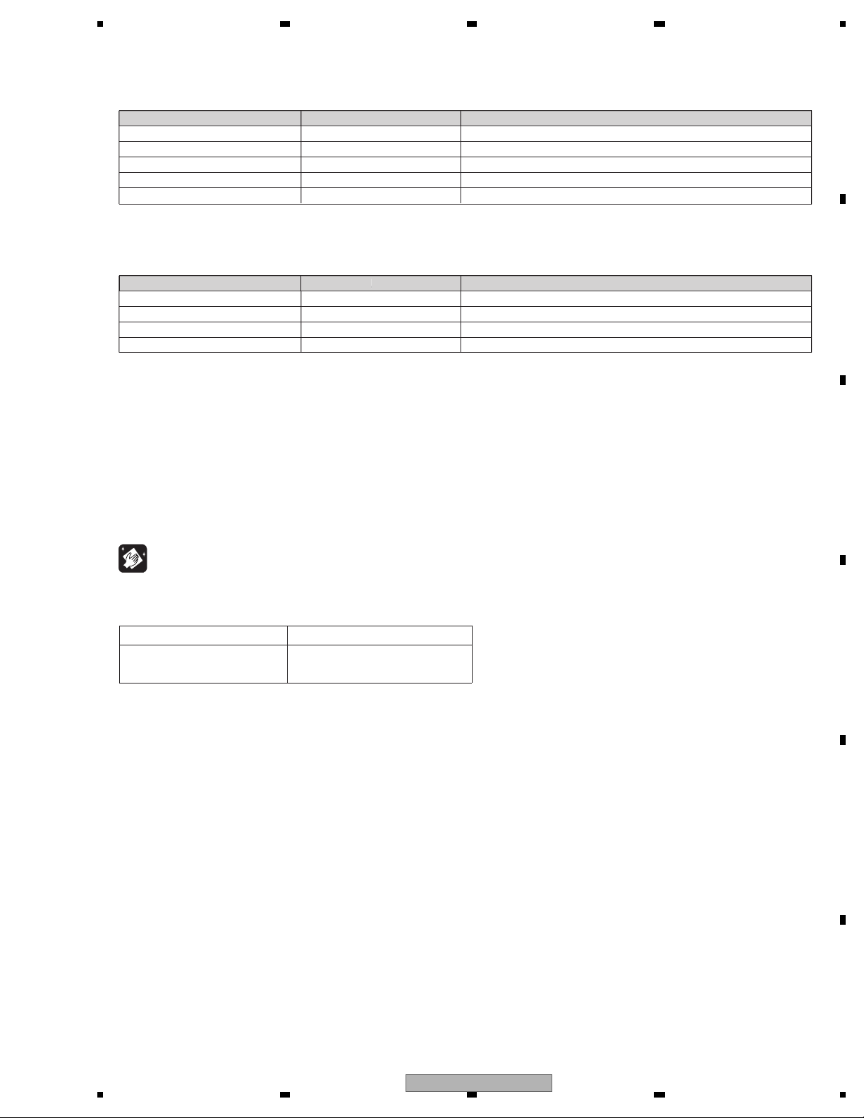
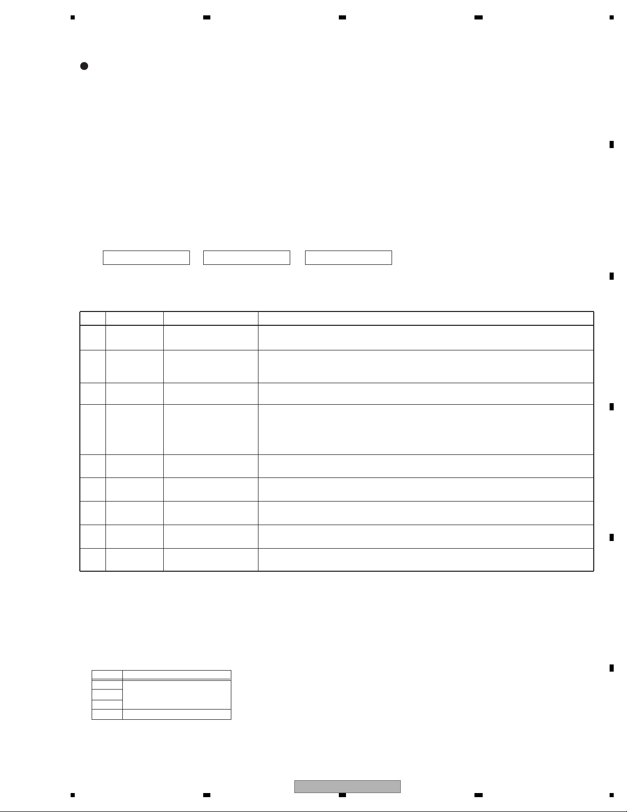
3. BASIC ITEMS FOR SERVICE
demrifnocebotmetIserudecorP.oN
1 Confirm whether the customer complain has
been solved.
If the customer complain occurs with the
specific media, use it for the operation check.
The customer complain must not be
reappeared.
Display, audio and operations must be
normal.
2 CD Play back a CD.
(Track search)
No malfunction on display, audio and
operation.
3 FM/AM tuner Check FM/AM tuner action.
(Seek, Preset)
Switch band to check both FM and AM.
Display, audio and operations must be
normal.
4 Check whether no disc is inside the product. The media used for the operating check must
be ejected.
retfaecnaraeppastinotridrosehctarcsoNkcehcecnaraeppA5
receiving it for service.
Item to be checked regarding audio
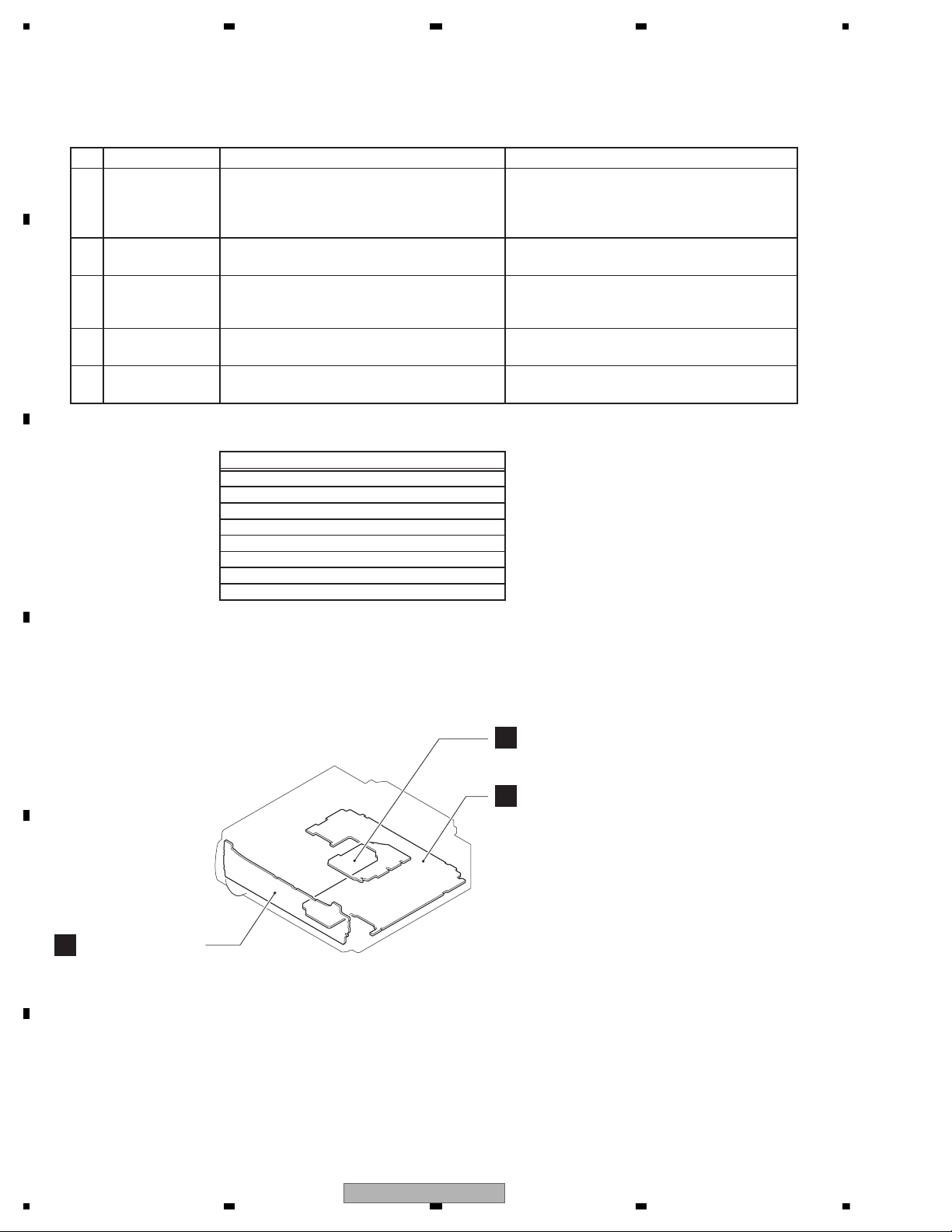
A
B
Keyboard Unit
Tuner Amp Unit
C
CD Core Unit (S11.6STD)
A:DEH-15UB/XNUC
B:DEH-1500UB/XNEW5
C:DEH-1500UBA/XNEW5
D:DEH-1500UBB/XNEW5
E:DEH-1500UBG/XNEW5
F:DEH-1550UB/XNES
H:DEH-1590UB/XNID
Unit Number : QWM3468(A)
Unit Number : QWM3465(B,D)
Unit Number : QWM3467(C)
Unit Number : QWM3466(E)
Unit Number : QWM3469(F)
Unit Number : QWM3471(H)
Unit Name : Tuner Amp Unit
Unit Number : (A,F,H)
Unit Number : (B)
Unit Number : (C)
Unit Number : (D)
Unit Number : (E)
Unit Name : Keyboard Unit
Unit Number : CWX4023
Unit Name : CD Core Unit (S11.6STD)
3.1 CHECK POINTS AFTER SERVICING
To keep the product quality after servicing, please confirm following check points.
See the table below for the items to be checked regarding audio:
Distortion
Noise
Volume too low
Volume too high
Volume fluctuating
Sound interrupted
3.2 PCB LOCATIONS
10
DEH-15UB/XNUC
5 678
56
7
8
C
D
F
A
B
E
- Jigs List
- Grease List
Name
Grease
Grease
Grease
Grease
Grease No.
GEM1024
GEM1038
GEM1043
GEM1045
Remarks
CD Mechanism Module
CD Mechanism Module
CD Mechanism Module
CD Mechanism Module
Name
G
Name
16P FFC
Test Disc
L.P.F.
Acetate Tape
Silicon Glue
Jig No.
GGD1310
TCD-782
GYH1026
GEM1017
Remarks
Tuner Amp Unit - CD Core Unit
Checking the grating
Checking the grating (Two pieces)
Capacitor Bond Lock
Capacitor Bond Lock
Before shipping out the product, be sure to clean the
following portions by using the prescribed cleaning
tools:
Portions to be cleaned Cleaning tools
CD pickup lenses Cleaning liquid : GEM1004
Cleaning paper : GED-008
3.3 JIGS LIST
rease No.
3.4 CLEANING
emarks
DEH-15UB/XNUC
11
1234
1234
C
D
F
A
B
E
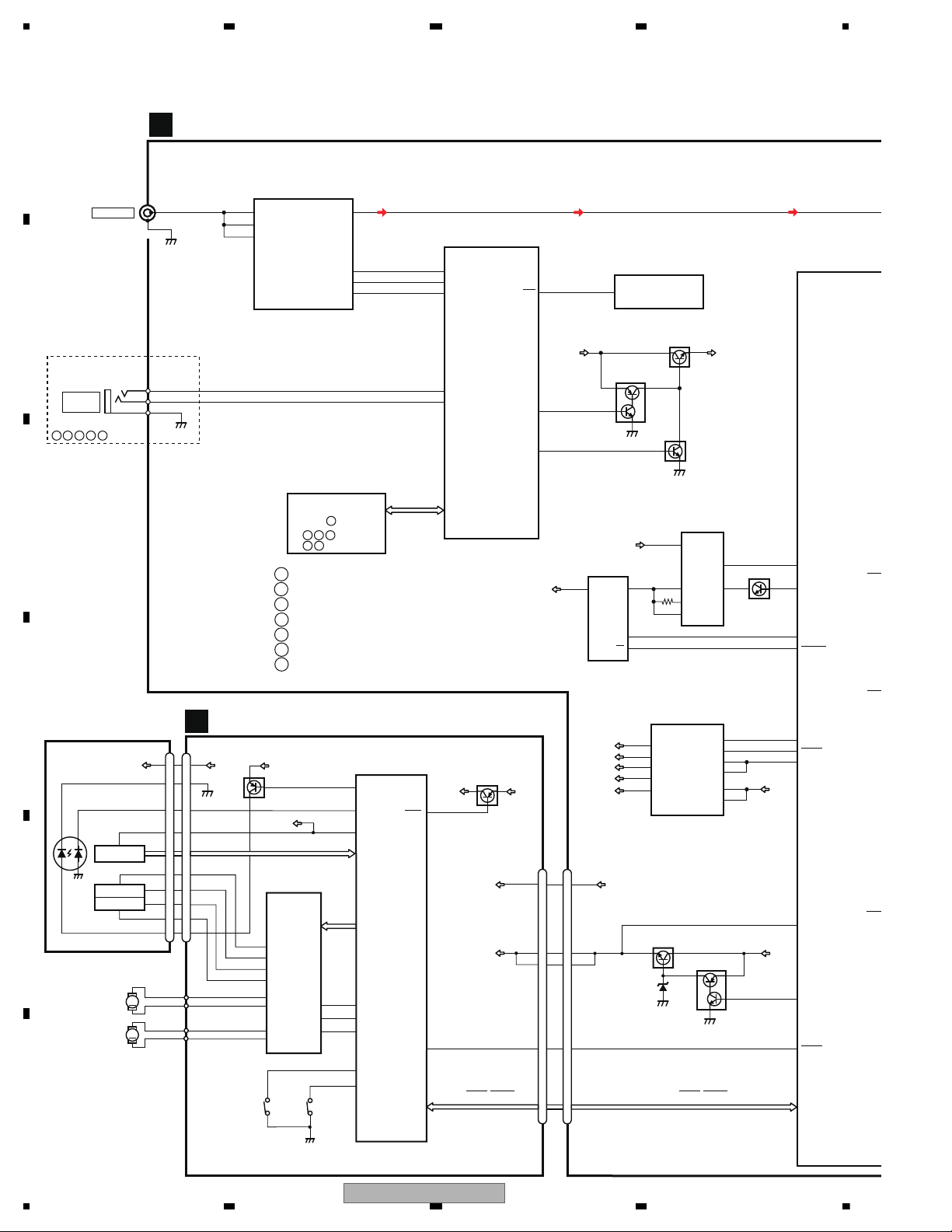
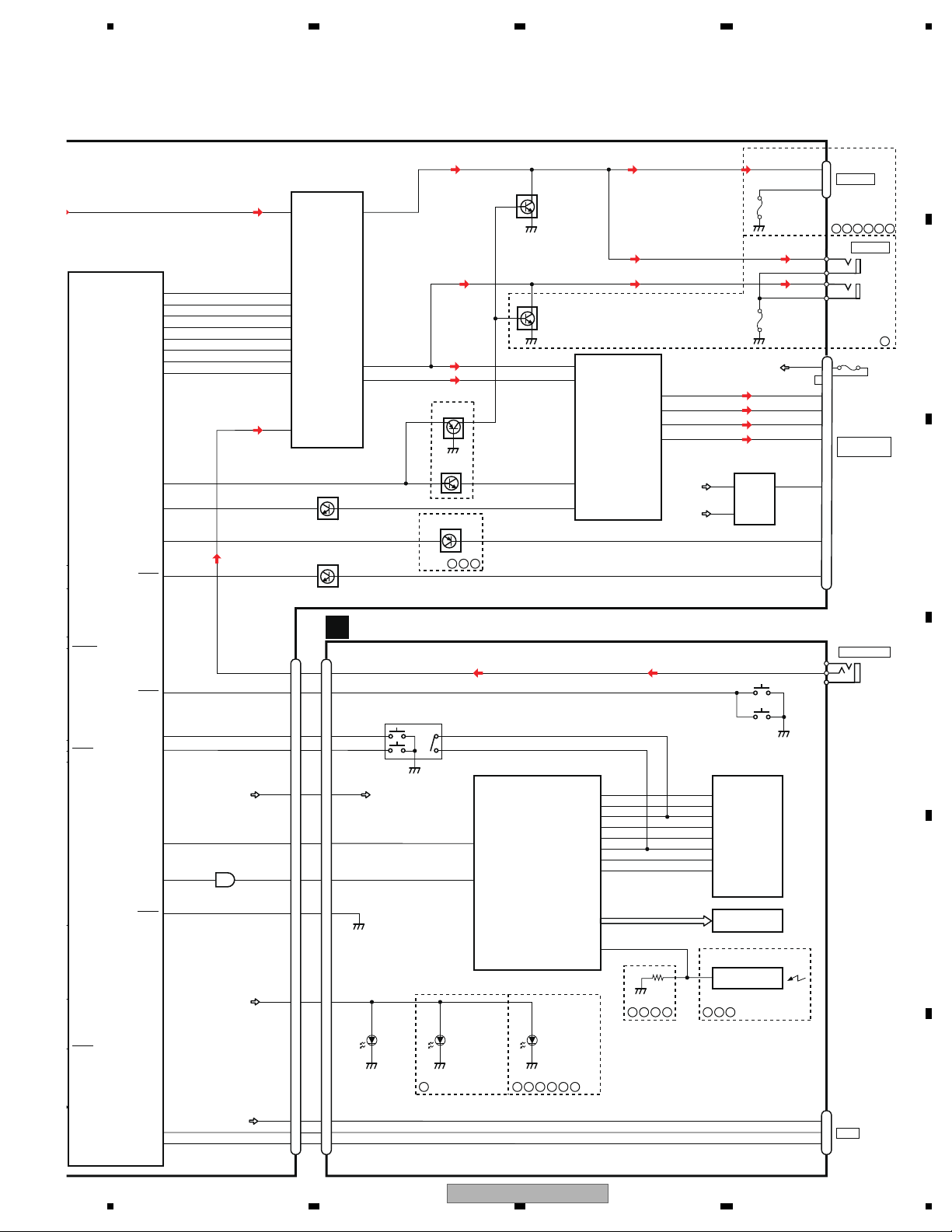
4. BLOCK DIAGRAM
MUT
ANTP
TEL
ASEN
JA401
1
2,3
CN701
ANTENNA
SSEN
ROT
ROT
ILMPW
19
RGBDT/DIMMER
21
DPD
KYD
DSEN
D
D
VDD3.3V
9
SWVDD
SW5V
9
6
BSENS
SYSPW
SWVDD
1
11
90
113
8
3
CDRST
8
RESET 33
2
B.UP
4
10
SYS+B
SWVDD
VDD12
SW5V
SYS+B
BSENS
SW5VCNT
+B
VCC
EN
DDON
VIN
EN
OC
+BUP
VDDCONT
SYSPW
5
USB5V
VOUT
5
SYNCSYNC
USBCTL
USBFLG
1185
986
1
8
119
1
3
1204
B.UP
Q751
2
1
Q752
VDCONT
85
VDSENS
55
MECHA VD
VD
B.UP
VDD
BD9876EFJ
IC551
BD2232G-G
IC552
SYSTEM MICRO
COMPUTER
(2/2)
IC601
R5S726A0D216FP
REGULATOR IC
IC911
BA49183-V12
RF FRONT END IC
IC401
TDA7706
5
FMMIXIN1
16
PINDIN
18
LNAIN
JA891
SYSTEM MICRO
COMPUTER
(1/2)
IC601
R5S726A0D216FP
VDD1.2V
VDD3.3V
VDD
8
7
TUN_SDA
TUN_SCL
33
34
57
94
93
TUNRES
31
88
KEYAD
56
KEYD
105
I2CSDA
RSTN
I2CSCL
DACOUTL
RES
139
RESET
IC671
S-80827CNMC-B8M
EVOL_RS
EVOL_C
EVOL_D
EVOL_DAT
EVOL_BC
EVOL_LRC
EVOL_MC
EVOL_C
FLASH ROM
IC681
:PEB046A8
:PEB047A8
CD DATA (CDSRQ,CDSTBY,SKIP,
SCL,SDA,DATA,BCLK,LRCK,WAIT)
TUNER AMP UNIT
A
2
3
1
USB5V REGULATOR
WIRED
REMOTE
KEYAD
KEYD
GND
FB
LX
4
BST
7
B.UP
ILM+B
Q875
Q873
Q874
Q601
CD CORE UNIT(S11.6 STD)
M
LD
MD
SPINDLE
M
LOADING/CARRIAGE
LD-
MD
15
5
HOLOGRAM
RF AMP, CD DECODER
2
VD
VD
9
3
SPO+
2
SPO-
5
SLLDO+
4
SLLDO-
22
LDIN
21
MUTE
TD,FD
AC,BD,E,F
SD,MD
LD+
14
1
LD
2
PD
CONT
LOEJ
HOME
35
41
39
VDD
1
VDD
VDD
15
5
FOCUS ACT.
TRACKING ACT.
FOP
TOP
2
1
TOP
FOP
7
TKO-
10
FCO+
2
1
14
DSCSNS
38
29
RESET
8
RESET
88
VREF
REFO
93
REFOUT
3
3
FOM
FOM
8
TKO+
4
4
TOM
TOM
9
FCO-
23
CNT
CLCONT
40
54
PUEN
V+3A
VDD
UNIT
MOTOR
MOTOR
ACTUATOR/
MOTOR DRIVER
BD8223EFV
HOMEDSCSNS
PE5791A
DIGITAL SERVO/DATA • PROCESSOR
CPU
CN701
Q101
CN101
Q102
IC301
S901
S903
IC201
C
V+3A
12
12
VCC
PD
REFO
LD+
SOP
SOM
LCOP
LCOM
PICKUP UNIT
(P10.6)(SERVICE)
GND
CD DATA (CDSRQ,CDSTBY,SKIP,
SCL,SDA,DATA,BCLK,LRCK,WAIT)
ILMPW
:DEH-15UB/XNUC
:DEH-1500UB/XNEW5
A
B
:DEH-1500UBA/XNEW5
C
:DEH-1500UBB/XNEW5
:DEH-1500UBG/XNEW5
D
E
:DEH-1590UB/XNID
H
:DEH-1550UB/XNES
F
EHFBD
A
EF
CBD
12
DEH-15UB/XNUC
5 678
56
7
8
C
D
F
A
B
E
FL
B.UP
117
17
MUTE
ANTPW
26
TELIN
89
ASENS
9
7
3
5
FL-
FL+
RL-
RL+
VDD OUT
IN
FL-
FL+
RL-
RL+
BREM81
3
ACC
22
25
Q941
Q302
MUTE
B.REM
CN801
ASENS
13
7
5
1
3
18
JA901
18
10
8
SOURCE
DPDT
KYDT
SSENS
35
ROT0
53
ROT1
54
DPDT
23
KYDT
22
FLIn
11
20
DSENS
DSENS
34
DM
49
DP
50
RLIn
12
MUTE
14
TEL
9
BSENS
SYSPW
SWVDD
CDRST
3
1
DDON
AUXL
19
SYNC
USBCTL
USBFLG
VDCONT
VDSENS
SYSTEM MICRO
COMPUTER
(2/2)
IC601
R5S726A0D216FP
AMP
IC301
PAL011A
Q301
(1/2)
Q301
(2/2)
JA251
Q252
INAN1L
40
33
OUTFL
34
OUTRL
35
OUTPL
ELECTRONIC VOLUME/
SOURCE SELECTOR
IC201
PM9013A
37
INBP4L
MCLK
LRCLK
BCLK
DIN
DATA
RESETB
CLK
STB
EVOL_RST
EVOL_CK
EVOL_DT
EVOL_DATA
EVOL_BCK
EVOL_LRCK
EVOL_MCK
EVOL_CS
19
20
21
22
23
26
24
25
81
104
103
106
110
87
108
111
Q951
11
USB5V
4
6
ROT0
ROT1
DM
DP
13
15
42
IC801
TC7SET08FUS1
3
SWVDD
TUNL
AUXL
TELIN
POWER
CONNECTOR
PL
B.UP
SYS+B
P251
KEYBOARD UNIT
USB
KYDT
DPDT
10
8
KEY MATRIX
4
6
2
1
5
4
3
AUXL
SOURCE
ROT0
ROT1
KDT2
KST1
18
19
LCD DRIVER/
KEY CONTROLLER
MULTI-CONTROL
PD6583A8
LCD
USB5V
DM
DP
4
2
DPDT
KYDT
15
KST3
7
KST2
5
KST1
3
KST0
24
KDT3
23
KDT2
22
KDT1
21
KDT0
11
13
15
3
2
3
4
USB5V
DM
DP
DSENS
ILM+B
20
55
CN1931
S1830
IC1801
V1801
CN1911
S1841
B
S1842
SWVDD
JA1921
FRONT AUX
AUXL
AUXGND 1
2
AUXR 3
RCA OUT
6
REM
GP1UXC14RK
SENSOR
REMOTE CONTROL
IC1941
1
B.REM&A.ANT
IC961
TPD1052F
D1952,D1953,
D1951
D1954,D1955,
D1956,D1957,
D1958,D1959,
D1960,D1961,
D1962,D1963,
D1964,D1965
D1967,D1968,
D1969,D1970,
D1971,D1972,
D1973,D1974,
D1975,D1976,
D1977,D1978,
D1979,D1980
ILM+B
D1966
DEHFBAC
ECBHFAD
DBE
FD
Q251
RCA OUT
JA251
P251
FL
PL
RCAG
6
3
14RCAG
H
EBA
C
D1981
(10A)
FUSE 10A
15
B.UP
17
DEH-15UB/XNUC
13
1234
1234
C
D
F
A
B
E
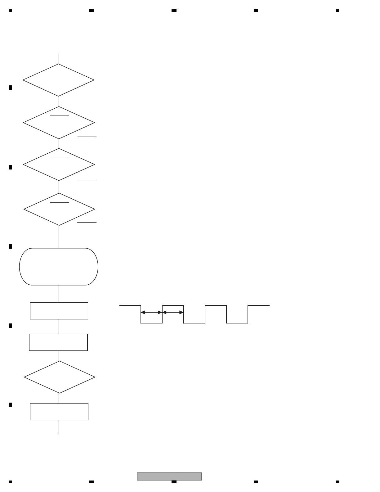
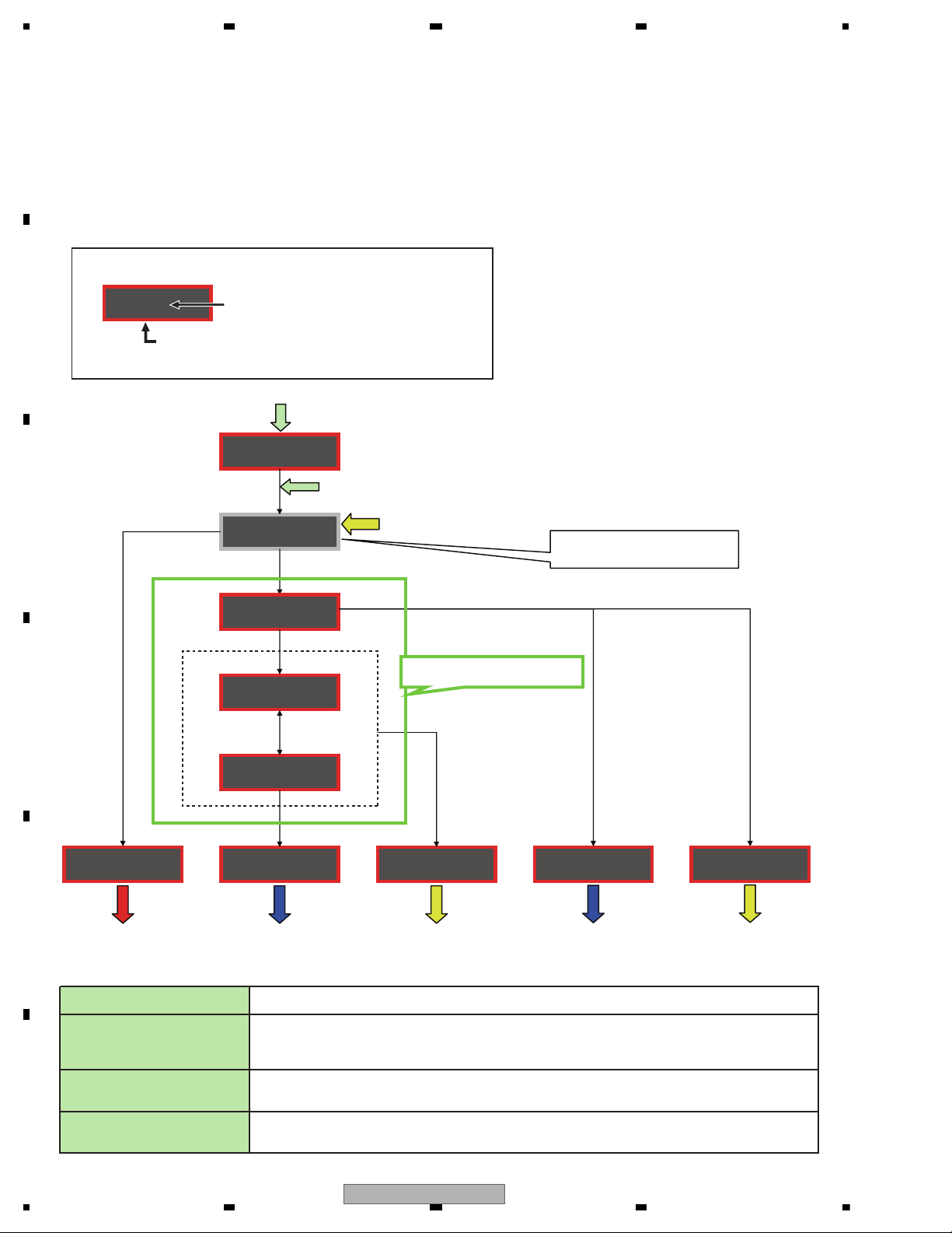
5. DIAGNOSIS
Vcc = 1.2 V
PVcc = 3.3 V
BSENS
Pin 90
ASENS
Pin 89
DSENS
Pin 34
BSENS = L
DSENS = L
Starts
communication
with Grille
microcomputer.
SWVDD <- H
Pin 113
Source keys
operative
Source ON
SYSPW <- H
Pin 8
300 ms
300 ms
In case of the above signal, the communication
with Grille microcomputer may fail.
If the time interval is not 300 msec, the oscillator
may be defective.
Completes power-on operation.
(After that, proceed to each source operation)
Power ON
ASENS = L
Vcc : Pin 12, 20, 43, 78, 86, 109
PVcc : Pin 3, 16, 28, 36, 48, 69, 82,101, 112
5.1 OPERATIONAL FLOWCHART
14
DEH-15UB/XNUC
5 678
56
7
8
C
D
F
A
B
E
8-digit display 6-digit display 4-digit display
ERROR-xx ERR-xx E-xx
(2) LIST OF CD ERROR CODES (Error Mode: 0xFD)
Code Classification
Error code to be displayed
Details and possible causes
10 Servo Carriage Home NG The pickup cannot move toward the inner track.
The CRG cannot move from the inner track.
--> Defective HOME SW; Failure in CRG movement.
07 Servo TOC reading NG TOC information cannot be read.
--> The partial disk or TOC content is illegal.
11 Servo Focus NG Focusing not available
--> Disc placed upside-down; Stains on the disc; excessive vibration.
17 Servo Setup NG The laser output cannot be adjusted. Focus can be easily lost.
--> Scratches or stains on the disc; excessive vibration.
15 Servo RF NG The digital signal from the disc cannot be detected.
--> A CD-R/RW disc that does not contain data loaded.
12 Servo Spindle Lock NG
Subcode NG
RF-amp NG
Spindle not locked. Subcode not readable.
Proper RF AMP gain not obtained.
--> Defective spindle; Scratches or stains on the disc; excessive vibration.
-->
A CD-R/RW disc that does not contain data loaded, or in a rare case, disc placed upside-down.
--> RF signal error.
30 Servo Search Time Out Failed to reach a target address. And, the search became a timeout.
--> Carriage/Tracking error; Scratches on the disc; Stains on the disc
50 Mechanism Load NG
Eject NG
Disc loading/ejection not completed
--> A foreign object inserted in the mechanism; Disc jammed.
51 Mechanism Failure in retried
turning for ejection
Disc could not be ejected even after disc turning had been retried.
--> A foreign object inserted in the mechanism; Disc jammed.
ERROR CODES
(1) DISPLAY METHOD
If “0xFD” error mode is displayed in CD MODE (CD MODE area for display), an error code will be displayed in the MIN (minute
display) and SEC (second display) areas.
The same code is displayed in the MIN and SEC areas.
The TNO area is blank (#0FFH), as it conventionally was.
• Display example of the head unit
Depending on the display capability of LCDs, the display format varies, as shown below. XX denotes an error number.
Note: In a case of an OEM product, the error display format is subject to the specifications used by the equipment
manufacturer.
If a CD memory device is inoperable, or operation of such media is stopped by an error, the error mode is established and a
cause of the error is displayed by an error code. Indication of error codes is intended to reduce the number of calls from
customers and facilitate failure analysis and repair work in servicing.
• The 2 high-order digits of an error code denote the main classification, shown below.
code classification
0x
1x Servo-related errors
3x
5x Mechanism-related errors
• How to restore from each error is shown below.
Servo-related errors(0X, 1X, 3X) : Servo-related errors CD Off, Eject, ACC Off, Back-up Off, Communication reset, Reset
Load NG/Eject NG(50) : Reload, Eject, ACC Off, Back-up Off, Communication reset, Reset
Failure in retried turning for ejection : CD On, Eject, ACC Off, Back-up Off, Communication reset, Reset
NOTES
• Indications of error codes are available only during disc operations, because CD operations are unavailable if a mechanical error is
generated.
• If the TOC cannot be read, It stops because of error 07.
• If you design a new head unit, be sure to use one of the display formats indicated in “Display example of the head unit.”
5.2 ERROR CODE LIST
DEH-15UB/XNUC
15

1234
1234
C
D
F
A
B
E
USB storage device
Message Cause Action
FORMAT
READ
Sometimes
there is a delay
between the
start of playback
and when you
start to hear any
sound.
Wait until the
message disappears and you
hear sound.
NO AUDIO There are no
songs.
Transfer the audio
files to the USB
storage device
and connect.
The connected
USB storage device has security enabled.
Follow the USB
storage device instructions to disable the security.
SKIPPED The connected
USB storage device contains
files embedded
with Windows
Media
™DRM 9/
10.
Play an audio file
not embedded
with Windows
Media DRM 9/10.
PROTECT All the files in
the USB storage
device are embedded with
Windows Media
DRM 9/10.
Transfer audio
files not embedded with
Windows Media
DRM 9/10 to the
USB storage device and connect.
N/A USB The USB device
connected to is
not supported
by this unit.
Connect a USB
Mass Storage
Class compliant
device.
Disconnect
your device and
replace it with a
compatible USB
storage device.
CHECK USB The USB con-
nector or USB
cable has shortcircuited.
Check that the
USB connector or
USB cable is not
caught in something or damaged.
The connected
USB storage device consumes
more than maximum allowable
current.
Disconnect the
USB storage device and do not
use it. Turn the
ignition switch to
OFF, then to ACC
or ON and then
connect only
compliant USB
storage devices.
Message Cause Action
ERROR-19 Communication
failed.
Perform one of
the following operations.
–Turn the ignition
switch OFF and
back ON.
–Disconnect the
USB storage device.
–Change to a different source.
Then, return to
the USB source.
ERROR-23 USB storage de-
vice was not formatted with
FAT12, FAT16 or
FAT32.
USB storage device should be formatted with
FAT12, FAT16 or
FAT32.
STOP There are no
songs in the
current list.
Select a list that
contains songs.
16
DEH-15UB/XNUC
5 678
56
7
8
C
D
F
A
B
E
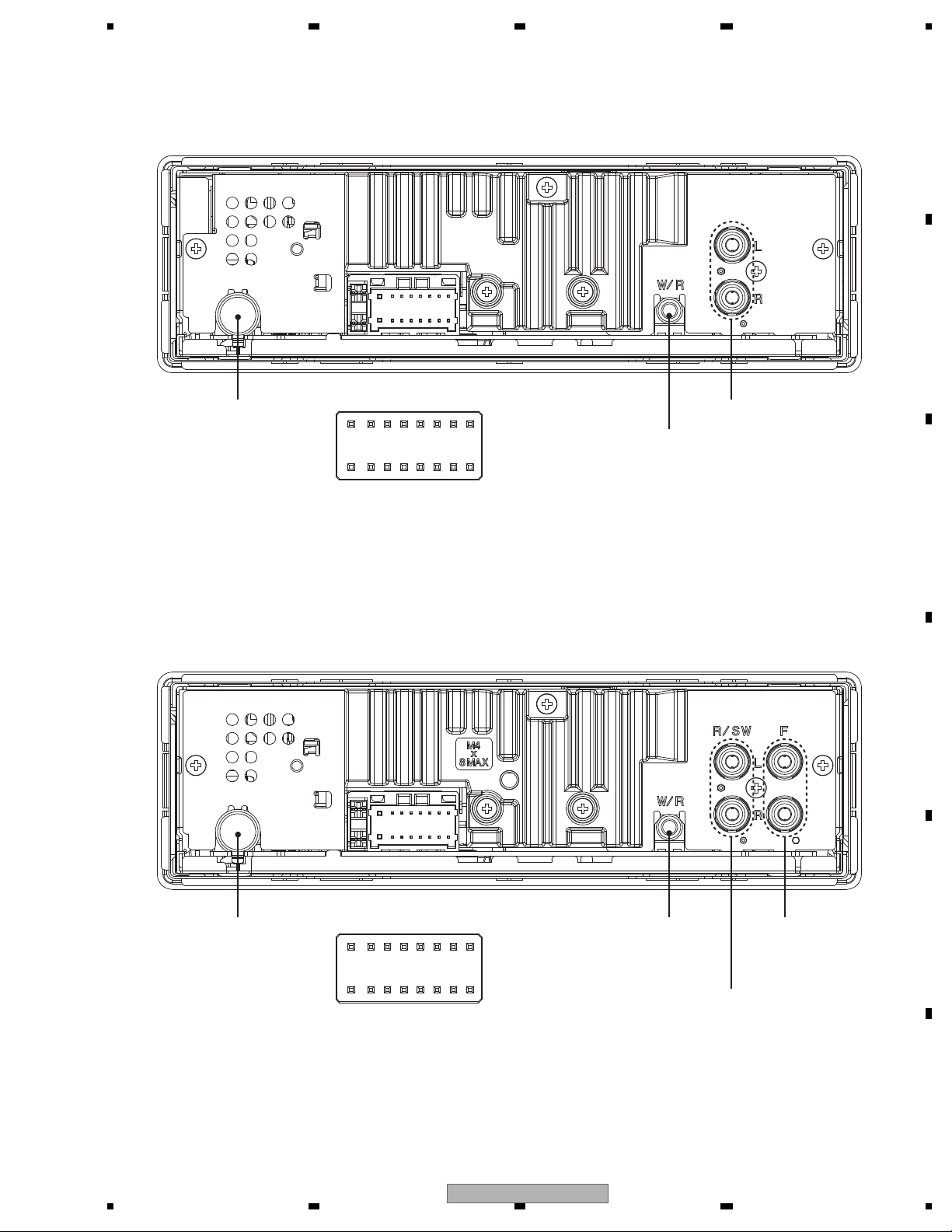
ANTENNA
1 FL+
2 FR+
3 FL4 FR5 RL+
6 RR+
7 RL8 RR-
9 NC
10 NC
11 NC
12 NC
13 ACC
14 B.REM
15 B.UP
16 GND
WIRED
REMOTE
CONTROL
REAR OUTPUT or
SUBWOOFER OUTPUT
FRONT
OUTPUT
ANTENNA
WIRED REMOTE CONTROL
(Except DEH-15UB/XNUC,
DEH-1500UBA/XNEW5)
REAR OUTPUT
16
14
12
10 8
6
42
15
13
11
97
5
31
1 FL+
2 FR+
3 FL4 FR5 RL+
6 RR+
7 RL8 RR-
9 NC
(DEH-15UB/XNUC,
DEH-1500UBA/XNEW5,
DEH-1550UB/XNES,
CELLULAR MUTE
(DEH-1500UB/XNEW5,
DEH-1500UBB/XNEW5,
DEH-1500UBG/XNEW5)
10 NC
11 NC
12 NC
13 ACC
14 B.REM
15 B.UP
16 GND
16
14
12
10 8
6
42
15
13
11
97
5
31
DEH-1590UB/XNID
DEH-15UB/XNUC, DEH-1500UBA/XNEW5,
DEH-1500UB/XNEW5, DEH-1500UBB/XNEW5, DEH-1500UBG/XNEW5, DEH-1550UB/XNES
5.3 CONNECTOR FUNCTION DESCRIPTION
DEH-15UB/XNUC
17
1234
1234
C
D
F
A
B
E
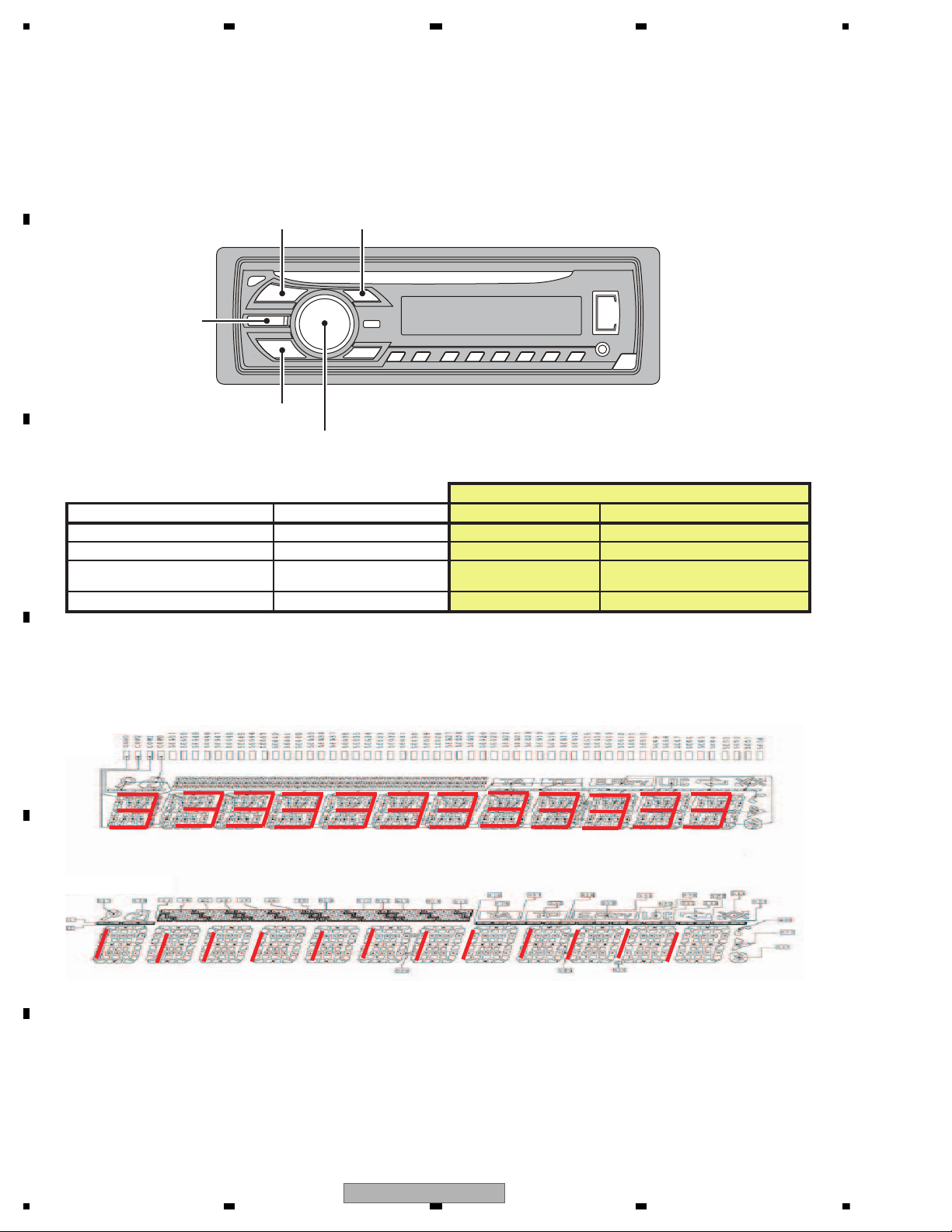
6. SERVICE MODE
Grille condition
Conf. item Operate Show LCD ILM
All light up
EQ + LIST
Draw 1 ILM(1)
All light off SOURCE No light Draw2 No light
Conf. LCD pattern 1
(* And change ILM color)
BAND Draw 3
ILM(2)
(If not have, ILM(1) light on)
Conf. LCD pattern 2
ROTARY center
Draw 4 ILM(1)
Drawings Style
Draw1 ALL light up
Draw2 ALL light off
Draw3
Draw4
BAND
SOURCE
EQ
LIST
ROTARY
Press and hold "EQ" and "LIST" buttons together, and turn BUP and ACC on.
[How to enter Test mode]
6.1 DISPLAY TEST MODE 1
18
DEH-15UB/XNUC
5 678
56
7
8
C
D
F
A
B
E
* Initial
condition
$ PD number
For Ver.7.01, "701" is displayed
For PEA010A, "010A" is displayed
# System
microcomputer
version
S
$$$$
###
1 + 3
On (state when
entering test mode)
Press and hold "1" and "3" buttons together, and turn BUP and ACC on.
[Operation key]
[How to enter Test mode]
[Test items]
Start display test mode.
Press and hold "1" and "3" buttons together, and turn
BUP and ACC on.
Display is normally updated
Display update is stopped
Product operation is performed as usual, in appearance.
The screen gets still when entering this item.
On (an initial value)
On (lighting condition
of normal times)
On (an initial value or
setting value of default
menu)
On (an initial value or
setting value of default
menu)
On (an initial value or
setting value of default
menu)
Off
All off
All off
All off
Remarks
Key Illumination
Operation key Processing
Icon
Enter display test mode
Switch to next test mode
The information such as the system microcomputer version is checked.
Switching to next display
by pressing “ 1 ” + “ 3 ” buttons together.
Switching to next display
by pressing “ 1 ” + “ 3 ” buttons together.
Switching to next display
by pressing “ 1 ” + “ 3 ” buttons together.
System Version information is displayed.
6.2 DISPLAY TEST MODE 2
DEH-15UB/XNUC
19
1234
1234
C
D
F
A
B
E
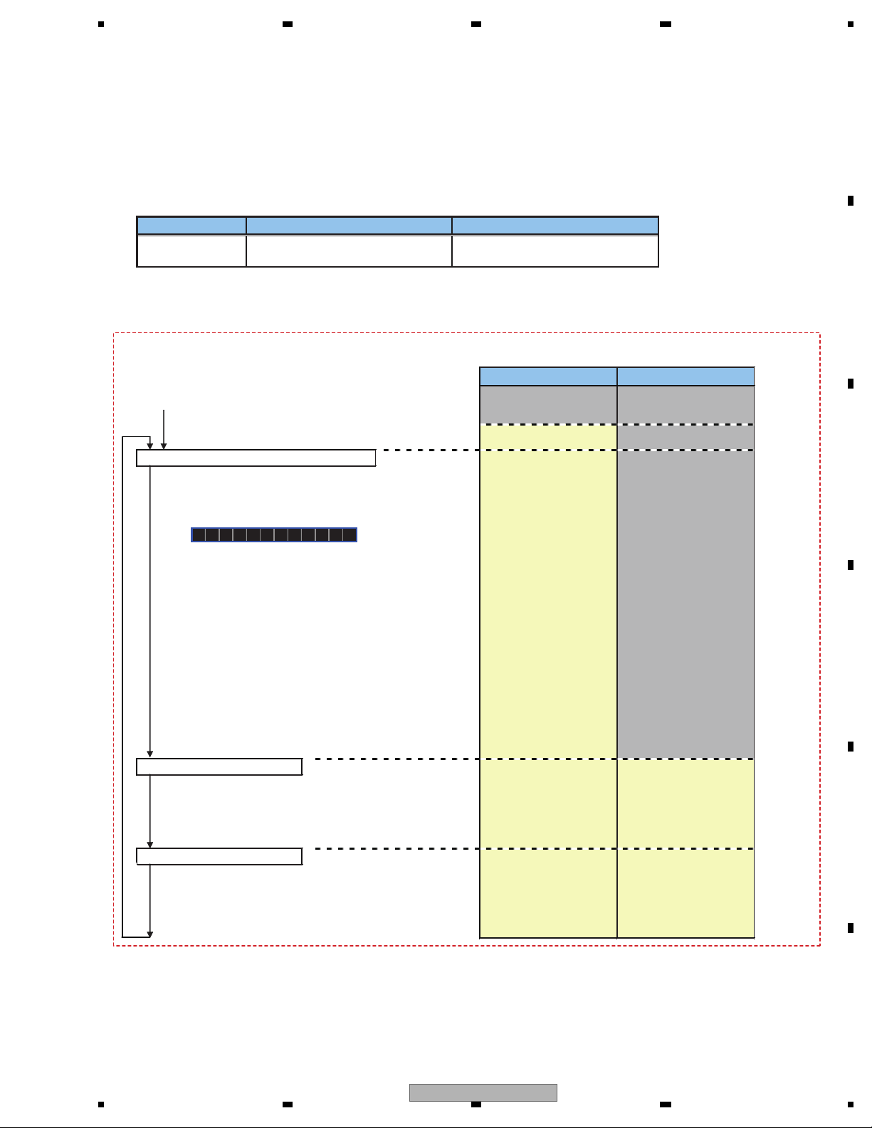
6.3 SOFTWARE VERSION UP METHOD
Overview
This mode is used for upgrading the MCU software of system using USB memory.
How to enter in USB rewriting mode
Press and hold "1" and "2" buttons together, and turn BUP and ACC on.
USB rewriting operation flow
Explanatory note
Screen display and ON/OFF of illumination
Characters displayed on the screen
Red frame: illumination lights up
Gray frame: illumination lights off
Blue characters: operation to be carried out by a user of USB rewriting function
Press and hold "1" and "2" buttons together, and turn BUP and ACC on.
Press LIST button
* After connecting USB memory in which upgrading file is stored, press LIST button.
(4) Retry count over
Retry rewriting
Check of upgrading file is started
(2) Upgrading file is not detected
Upgrading file error
After retryFirst time
Rewriting is started
Switched every
5 seconds
(3) Rewriting failed
(1) Rewriting succeeded
Result of rewriting
(1) Rewriting succeeded
(2) Upgrading file error
Upgrading file is not detected
(3) Rewriting failed
(4) Retry count over
FILE ERROR
DON'T STOP
PRG **/100
ERR->RETRYCAN'T UPDT
USB
START UPDT
CHECK FILE
In 5 seconds, usual operation
(OFF SOURCE)
As the reset is internally carried out,
display and illumination go out
In 5 seconds, usual operation
(OFF SOURCE)
In 5 seconds, rewriting
is retried
In 5 seconds, rewriting
is retried
Display is continued until
the power supply is turned
OFF
If the power supply is turned OFF
during rewriting, retry the rewriting.
Displayed when there is no upgrading file in USB memory or the data of upgrading file is different.
In 5 seconds, usual operation (OFF SOURCE) is started.
If the upgrading file error is detected or the upgrading file is not detected after the rewriting is retried, the rewriting is failed.
In 5 seconds, rewriting is retried.
Displayed when the retry becomes unavailable because the retry count is exceeded.
The display is continued until the power supply is turned OFF. If the power supply is turned ON again, the display is not changed.
The upgrading using USB is disabled, so it is necessary to write programs in serial Flash using E10A.
Displayed when the writing of upgrading file in serial Flash is not normally terminated.
Or, displayed if the upgrading file error is detected or the upgrading file is not detected after the rewriting is retried.
In 5 seconds, rewriting is retried.
Displayed when USB rewriting is normally terminated.
In 5 seconds, usual operation (OFF SOURCE) is started.
ERR->RETRY
COMPLETE
20
DEH-15UB/XNUC
5 678
56
7
8
C
D
F
A
B
E
[Key]
Contents
Display
[BAND]
Power On
(T.Offset is adjusted)
TRK MIN SEC
00 00 00
[2]
RF AMP
Gain switching
GG GG GG
*1
[3]
Focus Close
S curve check
TRK MIN SEC
91 91 91
[6]
Focus Mode switching
0X 0X 0X
*2
[1]
Tracking Servo
Close
00 00 00
or 99 99 99
[>]
CRG +
[2]
Self-adjusting
switching
TRK MIN SEC
?? ?? ??
*3*6
[<]
CRG -
*6
[BAND]
Power Off
TRK MIN SEC
[BAND]
Power Off
TRK MIN SEC
[BAND]
Power Off
TRK MIN SEC
[BAND]
Power Off
TRK MIN SEC
[1]
T.Close & AGC
Applicable servomechanism
TRK MIN SEC
?tr ?min ?sec
[3]
RF AGC /
RF AGC coefficient display
[>]
CRG +
8X 8X 8X
or 9X 9X 9X
[2]
T.Balance adjustment /
T.BAL coefficient display
TRK MIN SEC
?? ?? ??
[<]
CRG -
?? ?? ??
[1]
F,T,RF AGC
F.Bias display switching
TRK MIN SEC
TRK MIN SEC
TRK MIN SEC
[3] [>]
CRG/TR Jump +
[2]
Tracking Open
[<]
CRG/TR Jump -
?tr ?min ?sec
TRK MIN SEC
TRK MIN SEC
00 00 00
or 99 99 99
TRK MIN SEC
?tr ?min ?sec
8X 8X 8X
or 9X 9X 9X
8X 8X 8X
or 9X 9X 9X
00 00 00
or 99 99 99
TRK MIN SEC
?tr ?min ?sec?? ?? ??
*5
F,T AGC / F.Bias
RF AGC
8X 8X 8X
or 9X 9X 9X
[2]
Tracking Open
*6
*4 *4
Operation
[Key]
Test Mode
[BAND] Power On/Off
[>]
CRG + / TR Jump +
(Direction of the external surface)
[<]
CRG - / TR Jump (Direction of the internal surface)
[1] T. CLS & AGC & Applicable servomechanism /
AGC,AGC display setting
[2] RF Gain switching / Offset adjustment display /
T.Balance adjustment / T. Open
[3] F. Close,S. Curve / Rough Servo and RF AGC /
F,T,RF AGC
[6] F. Mode switching / Tracking Close
After the [EJECT] key is pressed keys other than the [EJECT] key should not be pressed, until disc ejection is complete.
When the key [2] or [3] is pressed during the Focus Search, the power supply should be immediately turned off (otherwise the lens sticks
to Wall, causing the actuator to be damaged).
In the case of 100TR Jump, the mechanism shall be set to the Tracking Close mode when the key is released.
When the power is turned on/off the gain of the RFAMP is reset to 0 dB. At the same time all the self-adjusting values shall return to the
default setting.
Do not do Tracking Servo Close before doing Focus Servo Close. (Because the overcurrent flows)
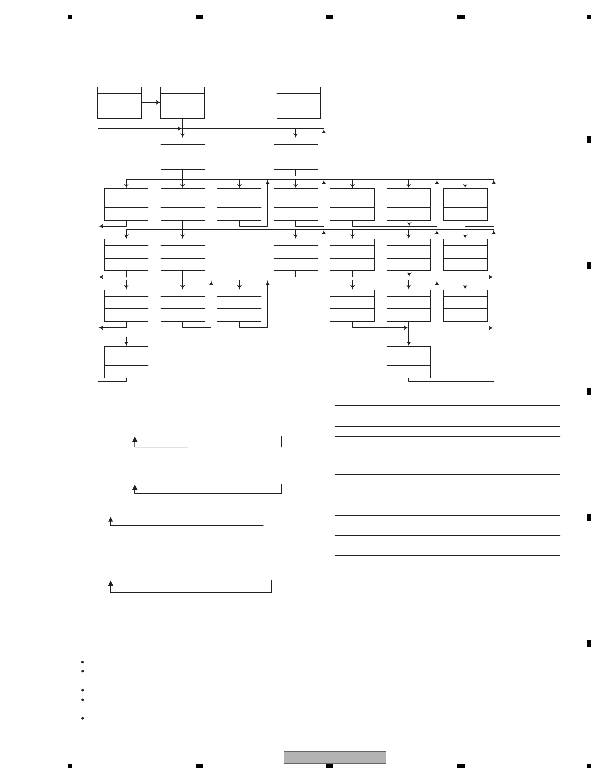
- Flow Chart
[CD] or [SOURCE]
Source ON
TRK MIN
[4]+[6]->BUP+ACC ON
Test Mode IN
*1) TYP t + 6 dB t + 12 dB
TRK
MIN
SEC
TRK06MIN06SEC
06
TRK12MIN12SEC
12
*2) Focus Close
t S. Curve t F EQ measurement setting
TRK00MIN00SEC
00
TRK
01
MIN01SEC
01
TRK02MIN02SEC
02
(
TRK99MIN99SEC
99)
*3) F.Offset Display t
*4) 100TR Jump
*5) TRK/MIN/SEC
t F.AGC t T.AGC Gain t F.Bias t RF AGC
*6) CRG motor voltage = 2 [V]
RF.Offset
Switch to the order
of the original
display
t
T.Offset Display t
6.4 CD TEST MODE
DEH-15UB/XNUC
21
 Loading...