

Page 1

Model No. Order No. CD Mechanism Module
FX-MG9127ZT/UC CRT2903 CXK7110
FX-MG9327ZT/ES CRT2904 CXK7110
FX-MG9427ZT/ES CRT2904 CXK7110
FX-MG9527ZT/Q1 CRT2904 CXK7110
FX-MG9327ZT/EW CRT2905 CXK7110
FX-MG9427ZT/EW CRT2905 CXK7110
FX-MG9727ZT/UC CRT2905 CXK7110
PIONEER CORPORATION 4-1, Meguro 1-Chome, Meguro-ku, Tokyo 153-8654, Japan
PIONEER ELECTRONICS (USA) INC. P.O.Box 1760, Long Beach, CA 90801-1760 U.S.A.
PIONEER EUROPE NV Haven 1087 Keetberglaan 1, 9120 Melsele, Belgium
PIONEER ELECTRONICS ASIACENTRE PTE.LTD. 253 Alexandra Road, #04-01, Singapore 159936
C PIONEER CORPORATION 2002
K-ZZS. JULY 2002 Printed in Japan
ORDER NO.
CRT2872
CD MECHANISM MODULE
CX-951
- This service manual describes the operation of the CD mechanism incorporated in models listed in the
table below.
- When performing repairs use this manual together with the specific manual for model under repair.
CONTENTS
1. CIRCUIT DESCRIPTIONS ...........................................2
2. MECHANISM DESCRIPTIONS.................................25
3. DISASSEMBLY .........................................................32
Page 2
2
1
234
12
34
F
E
D
C
B
A
CX-951
1. CIRCUIT DESCRIPTIONS
The LSI (UPD63711GC) used on this unit comprises six main blocks ; the pre-amp section, servo, signal processor,
DAC, CD text decoder and LPF. It also equips with nine automatic adjustment functions.
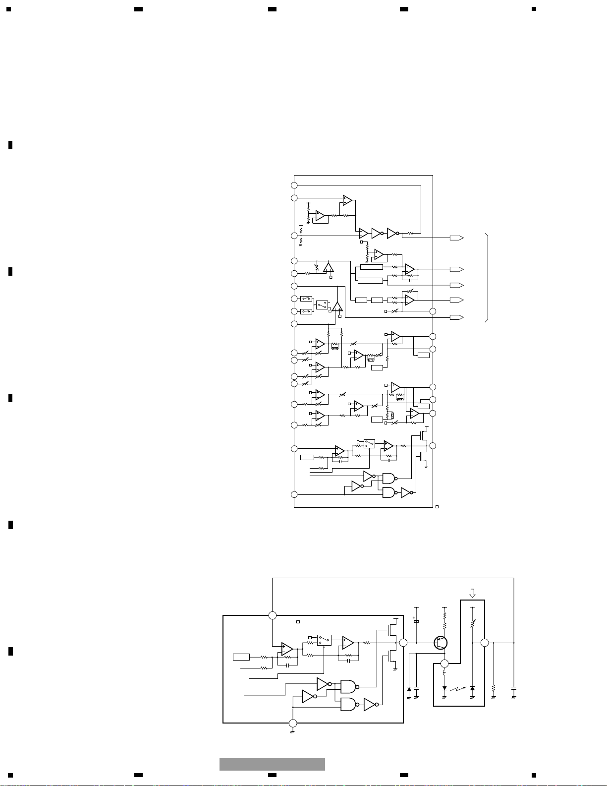
1.1 PRE-AMP SECTION
This section processes the pickup output signals to
create the signals for the servo, demodulator and
control.
The pickup output signals are I-V converted by the pre-
amp with the built-in photo-detector in the pickup, then
added by the RF amp to obtain RF, FE, TE, TE zero cross
and other signals.
This pre-amp section is built in the servo LSI
UPD63711GC (IC201). The following describes function
of each section.
Since this system has a single power supply (+5V), the
reference voltage for this LSI and pickup are set to
REFO (2.5V). The REFO is obtained by passing the
REFOUT from the LSI through the buffer amplifier. The
REFO is output from Pin 89 of this LSI. All
measurements are done using this REFO as reference.
Note : During the measurement, do not try to short the
REFO and GND.
1) APC Circuit (Automatic Power Control)
When the laser diode is driven with constant current,
the optical output has large negative temperature
characteristics. Thus, the current must be controlled
from the monitor diode so that the output may be
constant. APC circuit is for it. The LD current is obtained
by measuring the voltage between LD1 and V+5. The
value of this current is about 35mA.
71
72
74
76
AGCI
77
RFO
75
78
79
80
73
91
90
93
92
C-3T
FEO
FE-
TEO
TE-
85
86
87
E
97
PD
99
PN
F
D
82
83
84
B
C
A
RF-
EQ1
EQ2
AGCO
RFI
ASY
EFM
PEAK DET.
LPF
BOTTOM DET.
S/H
D/A
A/D
D/A
A/D
94
98
TE2
LD
VREG
GND
APN
LDON
EFM
DEFECT
FOK
A3T
MIRR
To the
following stage
of the LSI
Vref
Vref
Vref
Vref
Vref
Vref
Vref
Vref
Vref
Vref
Vref
Vref
Vref
Vref
Vref
·····Vref(+2.5V)
97
PD
99
PN
98
LD
VREG
GND
AMP_PN
(H:Nch L:Pch)
LDON
(H:LD MOVE L:STOP)
Vref
·····Vref(+2.5V)
32
23
R102
10
R101
12
Q101
2SB1132
C102
0.1µF
C103
100µF/6.3V
MECHANISM UNIT
R103
2.2k
C105
0.33µF
+5V
1k
110k
3p
3p
150k
100k
100k
16k
1k
D101
Fig.1 : BLOCK DIAGRAM OF BUILT-IN RF AMPLIFIER
Fig.2 : APC CIRCUIT
Page 3
5
6
7
8
5
6
7
8
F
E
D
C
B
A
CX-951
3
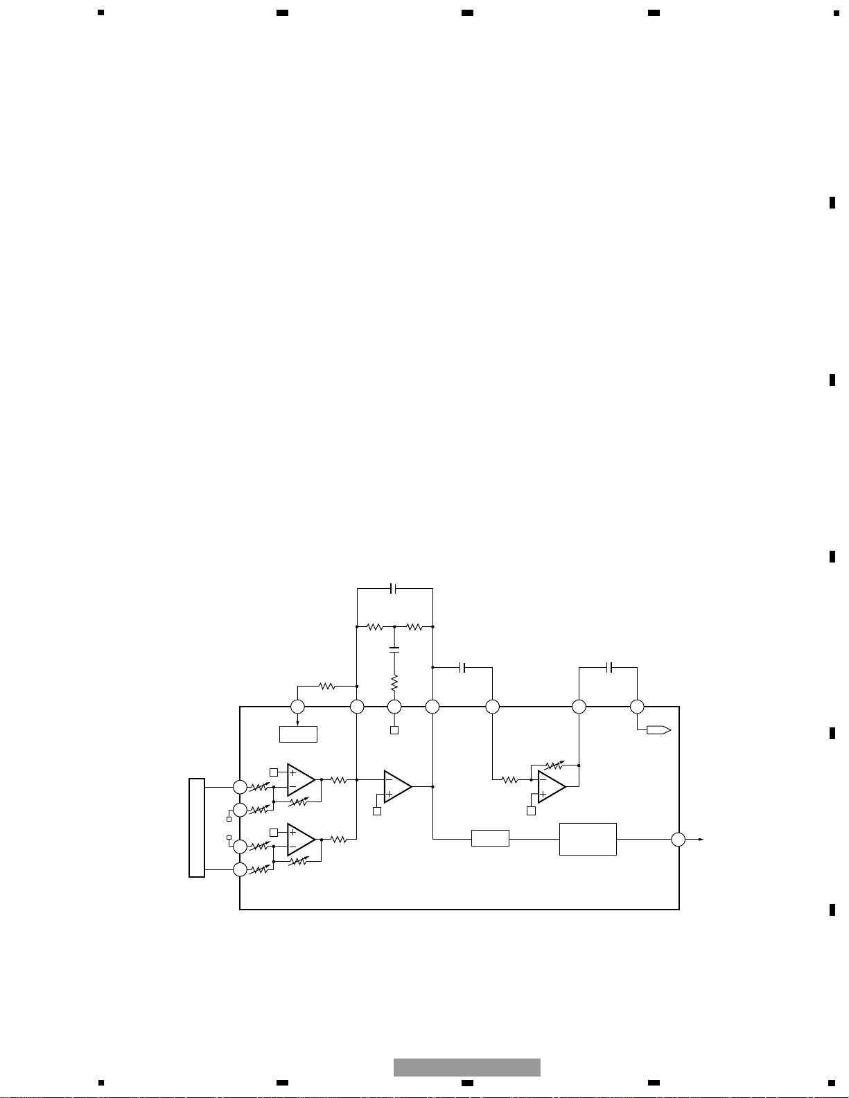
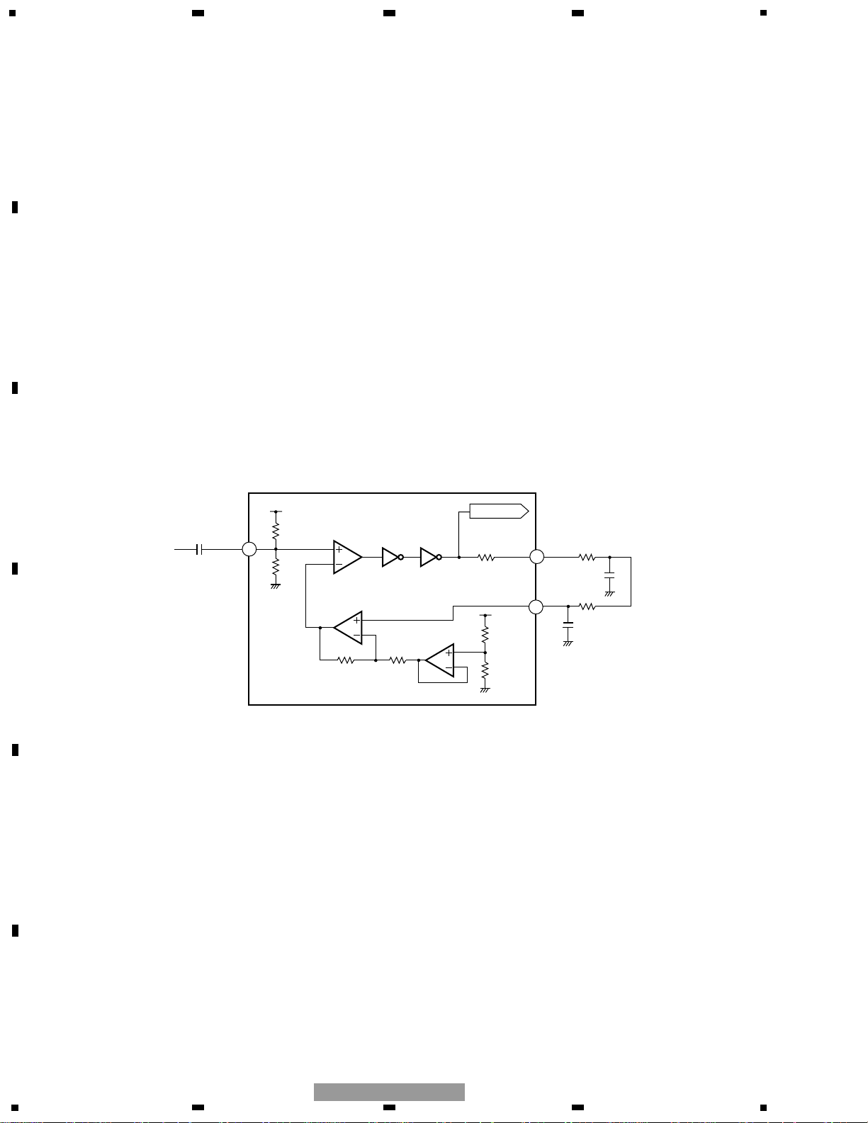
2) RF Amplifier and RFAGC Amplifier
The photo-detector outputs (A +C) and (B +D) are
added, amplified and equalized on this LSI and then
output to the RFI terminal as the RF signal. (The eye
pattern can be checked by this signal.)
The RFI voltage low frequency component is :
RFI = (A +B +C +D) ×3.2
RFI is used on the FOK generator circuit and RF offset
adjusting circuit.
R207 is an offset resistor for maintaining the bottom
reference voltage of the RFI signal at 1.5 VDC. The D/A
output used for the RF offset adjustment (to be
described later) is entered via this resistor.
After the RFI signal from Pin 77 is externally AC
coupled, entered to Pin 76 again, then amplified on the
RFAGC amplifier to obtain the RFO signal.
The RFAGC adjustment function (to be described later)
built-in the LSI is used for switching feedback gain of
the RFAGC amplifier so that the RFO output may go to
1.5 ±0.3Vpp.
The RFO signal is used for the EFM, DFCT, MIRR and
RFAGC adjustment circuits.
3) RFOK Circuit
This circuit generates the signal that is used for
indicating the timing of closing the focus or state of the
focus close currently being played. This signal is output
from Pin 4 as the FOK signal. It goes high when the
focus close and in-play.
The RFOK signal is generated by holding DC level of the
RFI at its peak with the succeeding digital section, then
comparing it at a specific threshold level. Thus, the
RFOK signal goes high even if the pit is absent. It
indicates that the focus close can take place on the disc
mirror surface, too.
This signal is also supplied to the micro computer via
the low pass filter as the FOK signal and used for the
protection and the RF amplifier gain switching.
CN101
84
24
31
83
82
10k
10k
85
FOK
CIRCUIT
A/D
4
A+C
16k
B+D
10k
16k
10k
R214
12k
C209 2pF
R212
5.6k
R207
0
C208
18pF
R213
15k
80 79 74757677
D/A
12k
66
10k
RFOAGCIRFI
C215
0.22µF
C213
1500pF
FOK
TO EFM
CIRCUIT
Fig.3 : RFAMP, RFAGC AND FOK CIRCUIT
Page 4
4
1
234
12
34
F
E
D
C
B
A
CX-951
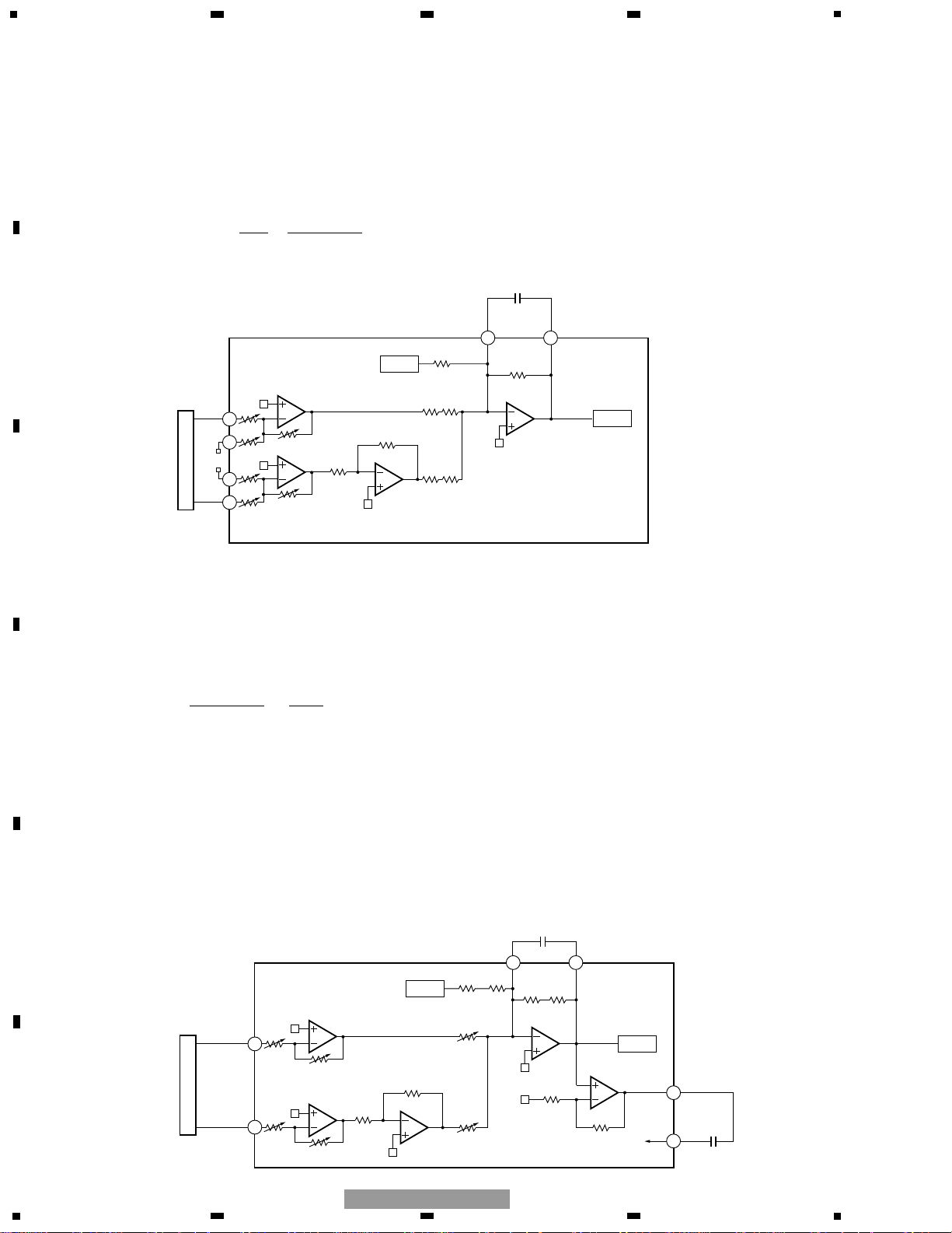
Fig.5 TRACKING ERROR AMPLIFIER AND TRACKING ZERO CROSSING AMPLIFIER
4) Focus Error Amplifier
The photo-detector outputs (A+C) and (B+D) are passed
through a differential amplifier and an error amplifier, and
then (A+C−B−D) is output from Pin 91 as the FE signal.
The FE voltage low frequency component is :
FE = (A + C − B − D) ××
= (A + C − B − D) × 5
Using REFO as the reference, an S-curve of approximately 1.5
Vpp is obtained for the FE output. The final-stage amplifier
cutoff frequency is 11.4 kHz.
5) Tracking Error Amplifier
The photo-detector outputs E and F are passed through
a differential amplifier and an error amplifier, and then
(E −F) is output from Pin 93 as the TE signal. The TE
voltage low frequency component is :
TE =(E −F)
××
=
(E −F) ×6.6 (Effective LSI output is 5.0).
Using REFO as the reference, the TE waveform of
approximately 1.3 Vpp is obtained for the TE output.
The final-stage amplifier cutoff frequency is 20 kHz.
6) Tracking Zero Crossing Amplifier
TEC signal (the tracking zero crossing signal) is
obtained by multiplying the TE signal four times. It is
used for locating the zero crossing points of the
tracking error. The zero cross point detection is done for
the following two reasons :
1
To count tracks for carriage moves and track jumps.
2
To detect the direction in which the lens is moving
when the tracking is closed (it is used on the
tracking brake circuit to be described later).
The TEC signal frequency range is 300 Hz to 20 kHz.
TEC voltage =TE level ×4
Theoretical TEC level is 5.2V. The signal exceeds D-
range of the operational amplifier and thus is clipped.
It, however, can be ignored since this signal is used by
the servo LSI only at the zero crossing point.
20k5k
CN101
84
24
31
83
82
10k
20k
5k
85
A+C
16k
B+D
48k
16k
10k
9190
D/A
80k
110k
FE
C219 180pF
A/D
FE OFFSET
TO DIG. EQ
48k
48.7k
CN101
27
28
86
112k
48.7k
87
F
E
F
224k
E
48k
224k
112k
9392
D/A
80k
110k
TE
C220 51pF
80k
110k
A/D
TE OFFSET
TO DIG. EQ
48k
60k
20k
95
94
TE2
TEC
C221
6800pF
16k
10k
80k
(20k + 5k)
Fig.4 : FOCUS ERROR AMPLIFIER
224k
112k
160k
48.7k
Page 5
5
5
6
7
8
5
6
7
8
F
E
D
C
B
A
CX-951
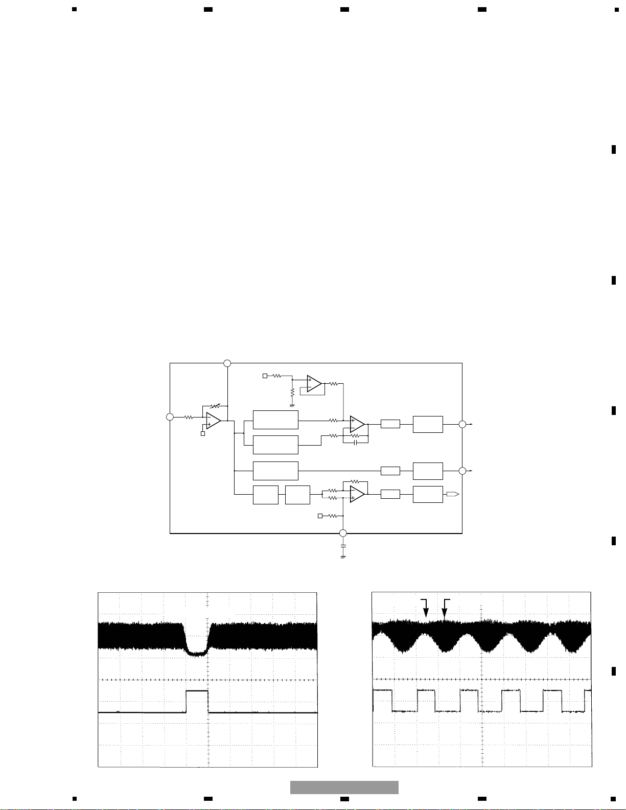
7) DFCT (Defect) Circuit
The DFCT signal is used for detecting defects on the
mirrored disc surface. It allows monitoring from the
HOLD pin (Pin 2). It goes high when defects are found
on the mirrored surface.
The DFCT signal is generated by comparing the RF
amplified signal (which is obtained by bottom holding
the RFO signal) at a specific threshold level by the
succeeding digital section.
Stains or scratches on the disc can constitute the
defects on the mirrored disc surface. Thus, as long as
the DFCT signal remains high in the LSI, the focus and
tracking servo drives are held in the current state so
that a better defect prevention may be ensured.
8) 3TOUT Circuit
The 3TOUT signal is generated by entering disturbance
to the focus servo loop, comparing phase of
fluctuations of the RF signal 3T component against that
of the FE signal at that time, then converting the signal
to DC level. This signal is used for adjusting bias of the
FE signal (to be described later). This signal is not
output from the LSI, thus its monitoring is not available.
9) MIRR (Mirror) Circuit
The MIRR signal shows the on track and off track data,
and is output from Pin 3.
When the laser beam is
On track : MIRR ="L"
Off track : MIRR ="H"
This signal is used on the brake circuit (to be described
later) and also as the trigger to turn on track counting
when jumping take place.
The MIRR signal is supplied to the micro computer, too,
for the protection purpose.
A/D
MIRR
CIRCUIT
3T
CIRCUIT
DFCT
CIRCUIT
BOTTOM DETECT
BOTTOM DETECT
PEAK DETECT
LPFS/H
A/D
A/D
76
75
73
3
2
40k
20k
20k
40k
40k
40k
200k
200k
C212
0.1µF
C3T
AGCI
RFO
12k
10k
20k
30k
MIRR
HOLD
Fig.6 : DFCT, MIRR AND 3T DETECTION CIRCUIT
Fig.7 : HOLD OUTPUT WAVEFORM
(When surface defects are present)
Fig.8 : MIRR OUTPUT WAVEFORM
(When an access is made)
Surface defects
RFI
HOLD
RFI
MIRR
OFF Track ON Track
Page 6
6
1
234
12
34
F
E
D
C
B
A
CX-951
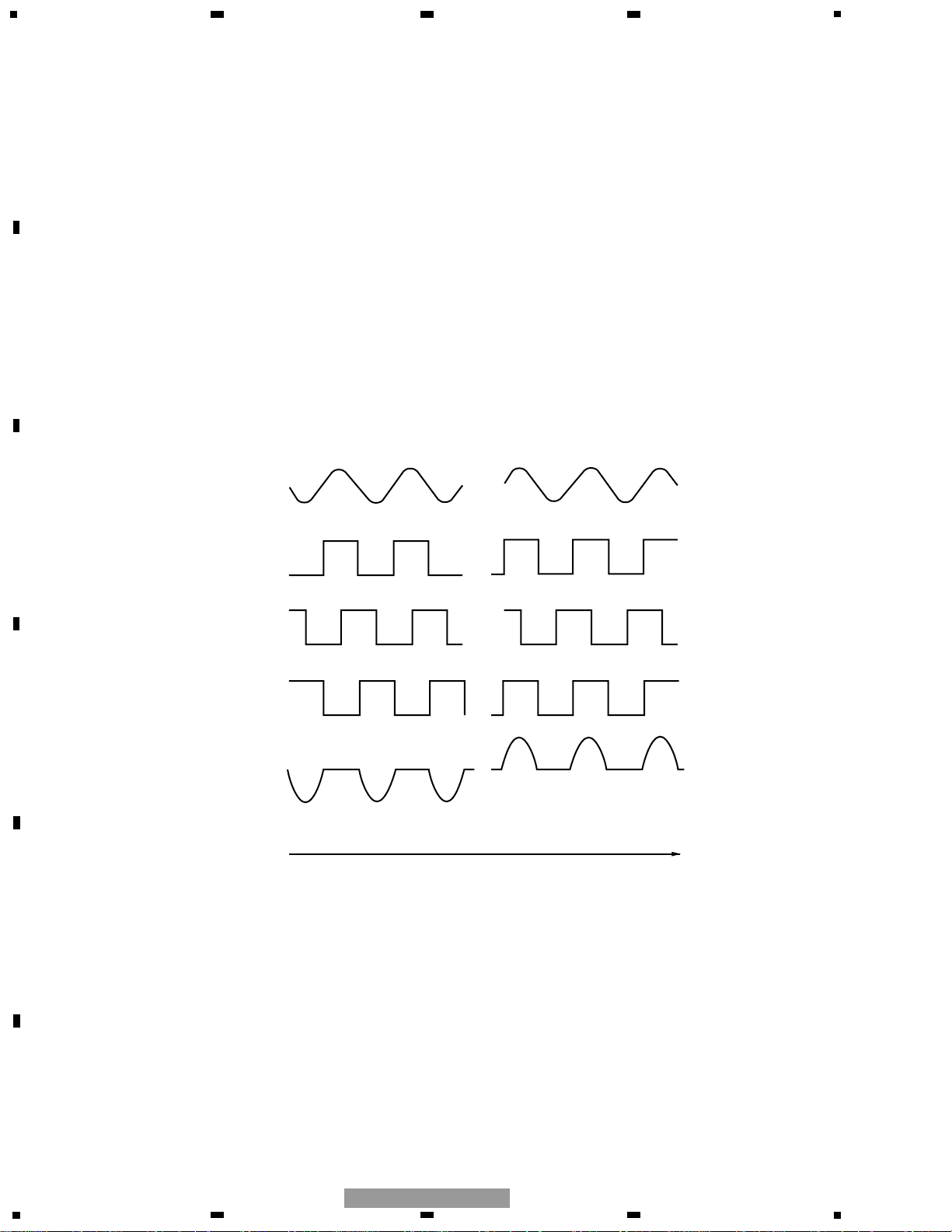
10) EFM Circuit
This circuit is used for converting the RF signal to
digital signal consisting of “0” and “1”. The RFO signal
from Pin 75 is externally AC coupled, entered to Pin 74,
then applied to the EFM circuit.
Loss of the RF signal due to scratches or stains on the
disc, or vertical asymmetry of the RF due to variations
in the discs manufactured can’t be eliminated by AC
coupling alone. This circuit, therefore, controls the
reference voltage ASY on the EFM comparator by use
of the fact that “0” and “1” appear fifty fifty in the EFM
signal. By this arrangement, the comparate level is
constantly maintained at almost center of the RFO
signal level. The reference voltage ASY is generated
when the EFM comparator output is passed through
the low pass filter. The EFM signal is output from Pin
71. It is a 2.5 Vp-p amplitude signal centering on REFO.
74
RFI
40k
40k
C206
1500pF
72
71
ASY
EFM
40k
40k
15k75k
2k
R205
10k
R206
39k
C203
0.047µF
C204
1800pF
EFM. SIG
Fig.9 : EFM CIRCUIT
Page 7
7
5
6
7
8
5
6
7
8
F
E
D
C
B
A
CX-951
The servo section controls the operations such as error
signal equalizing, in focus, track jump and carriage
move. The DSP is the signal processing section used
for data decoding, error correction and interpolation
processing, among others.
This circuit implements analog to digital conversion of
the FE and TE signals generated on the pre-amplifier,
then outputs them through the servo block as the drive
signal used on the focus, tracking and carriage system.
The EFM signal is decoded on the signal processing
section and finally output via the D/A converter as the
audio signal. The decoding process also generates the
spindle servo error signals which is fed to the spindle
servo block to generate the spindle drive signal.
The focus, tracking, carriage and spindle drive signals
are then amplified on the driver IC BD7962FM (IC301)
and fed to respective actuators and motors.
1) Focus Servo System
The focus servo main equalizer is consisted of the
digital equalizer. Fig.10 shows the focus servo block
diagram.
When implementing the focus close on the focus servo
system, the lens must be brought within the in-focus
range. Therefore, the lens is moved up and down
according to the triangular focus search voltage to find
the focus point. During this time, the spindle motor is
kicked and kept rotating as a set speed.
The servo LSI monitors the FE and RFOK signals and
automatically carries out the focus close at an
appropriate point.
The focus closing is carried out when the following
three conditions are met :
1
The lens approaches the disc from its current
position.
2
RFOK ="H"
3
The FZC signal is latched at high after it has once
crossed the threshold set on the FZD register (Edge
of the FZD).
As the result, the FE ( =REFO) is forced to low.
FE
AMP
DIG.
EQ
82
A+C
B+D
FD
FOP
FOM
IC301
BD7962FM
LENS
IC201 UPD63711GC
85
62
11
18
17
FOCUS SEARCH
TRIANGULAR
WAVE GENERATOR
DAC
CONTROL
A/D
R301
10K
R302
15K
10
Fig.10 : FOCUS SERVO BLOCK DIAGRAM
1.2 SERVO SECTION (UPD63711GC : IC201)
Page 8
8
1
234
12
34
F
E
D
C
B
A
CX-951
When the above conditions are all met and the focus is
closed, the XSI pin goes to low from the current high,
then 40 ms later, the microcomputer begins to monitor
the RFOK signal after it that has been passed through
the low pass filter.
When the RFOK signal is recognized as low, the micro
computer carries out various actions including
protection.
Fig.11 a series of operations carried out relevant to the
focus close (the figure shows the case where focus
close is not available).
You can check the S-curve, search voltage and actual
lens behavior by selecting the Display 01 for the focus
mode select in the test mode, and then pressing the
focus close button.
REFO
FD
LENS POSITION
RELATIVE TO DISC
NEAR
FAR
"JUST FOCUSED"
MD
REFO
Expanding around "Just Focused Point"
REFO
RFI
FOK
FE
FZD
THRESHOLD
LEVEL
FZD
(INTERNAL SIGNAL)
Focus closing would normally take place at these points
XSI
(IN THE EVENT
FOCUS IS
CLOSED)
LEVEL
Fig.11 : FOCUS CLOSE SEQUENCE
Page 9
9
5
6
7
8
5
6
7
8
F
E
D
C
B
A
CX-951
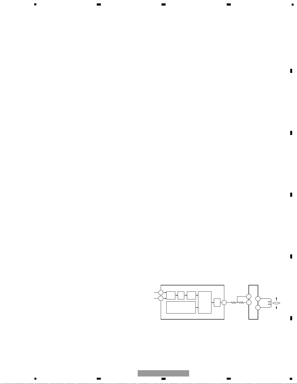
2) Tracking Servo System
The digital equalizer is employed for the main equalizer
on the tracking servo. Fig.12 shows the tracking servo
block diagram.
a) Track jump
When the LSI receives the track jump command from
the microcomputer, the operation is carried out
automatically by the auto sequence function of the LSI.
This system has five types of track jumps used for the
search : 1, 4, 10, 32 and 32 ×3. In the test mode, in
addition to three jumps (1, 32 and 32 ×3), move of the
carriage can be check by mode selection. For track
jumps, the microcomputer sets almost half of tracks (5
tracks for 10 tracks, for instance) and counts the set
number of tracks using the TEC signals. When the
microcomputer has counted the set number of tracks, it
outputs the brake pulse for a fixed period of time
(duration can be specified with the command) to stop
the lens. In this way, the tracking is closed and normal
play is continued.
To improve the servo loop retracting performance just
after the track jump, the brake circuit is turned on for 50
ms after the brake pulse has been terminated to
increase gain of the tracking servo.
Fast forward and reverse operations are realized by
through consecutive signal track jumps. The speed is
about 10(or 20) times as fast as that in the normal
mode.
TE
AMP
DIG.
EQ
86
F
E
TD
TOM
TOP
IC301
BD7962FM
LENS
IC201 UPD63711GC
87
63
12
13
16
15
JUMP
PARAMETERS
DAC
CONTROL
A/D
R304
10k
R303
10k
t1
t2
GAIN NORMAL
TD
KICK
BRAKE
TEC
T. BRAKE
EQUALIZER
T. SERVO
CLOSED
OPEN
NORMAL
GAIN UP
OFF
ON
t1
TD
TEC
(10 TRACK)
EQUALIZER
T. BRAKE
SERVO
SD
2.9mS (4.10 TRACK JUMP)
5.8mS (32 TRACK JUMP)
GAIN UP
NORMAL
ON
OFF
OPEN
CLOSED
t2
50mS
t
Fig.12 : TRACKING SERVO BLOCK DIAGRAM
Fig.13 : SINGLE TRACK JUMP
Fig.14 : MULTI-TRACK JUMP
Page 10
10
1
234
12
34
F
E
D
C
B
A
CX-951
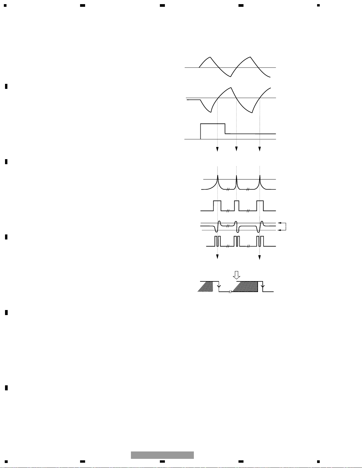
b) Brake Circuit
The servo retracting performance can be deteriorate
during the setup or track jump operation. In this
connection, the brake circuit is used to ensure steady
retract of the tracking servo. The brake circuit detects in
which direction the lens is moving, then slows down its
move by outputting the drive signal that moves the
lens into the opposite direction alone. Track slippage
direction is determined by referencing the TEC and
MIRR signals and their phase.
TEC
TZC
(TEC "SQUARED UP" )
(INTERNAL SIGNAL )
MIRR
MIRR LATCHED AT
TZC EDGES
=
SWITCHING PULSE
EQUALIZER OUTPUT
(SWITCHED)
DRIVE DIRECTION
Note : Equalizer output assumed to hava same phase as TEC.
FORWARD
LENS MOVING FORWARDS
(INNER TRACK TO OUTER)
LENS MOVING BACKWARDS
Time
REVERSE
Fig.15 : TRACKING BRAKE CIRCUIT
Page 11
11
5
6
7
8
5
6
7
8
F
E
D
C
B
A
CX-951
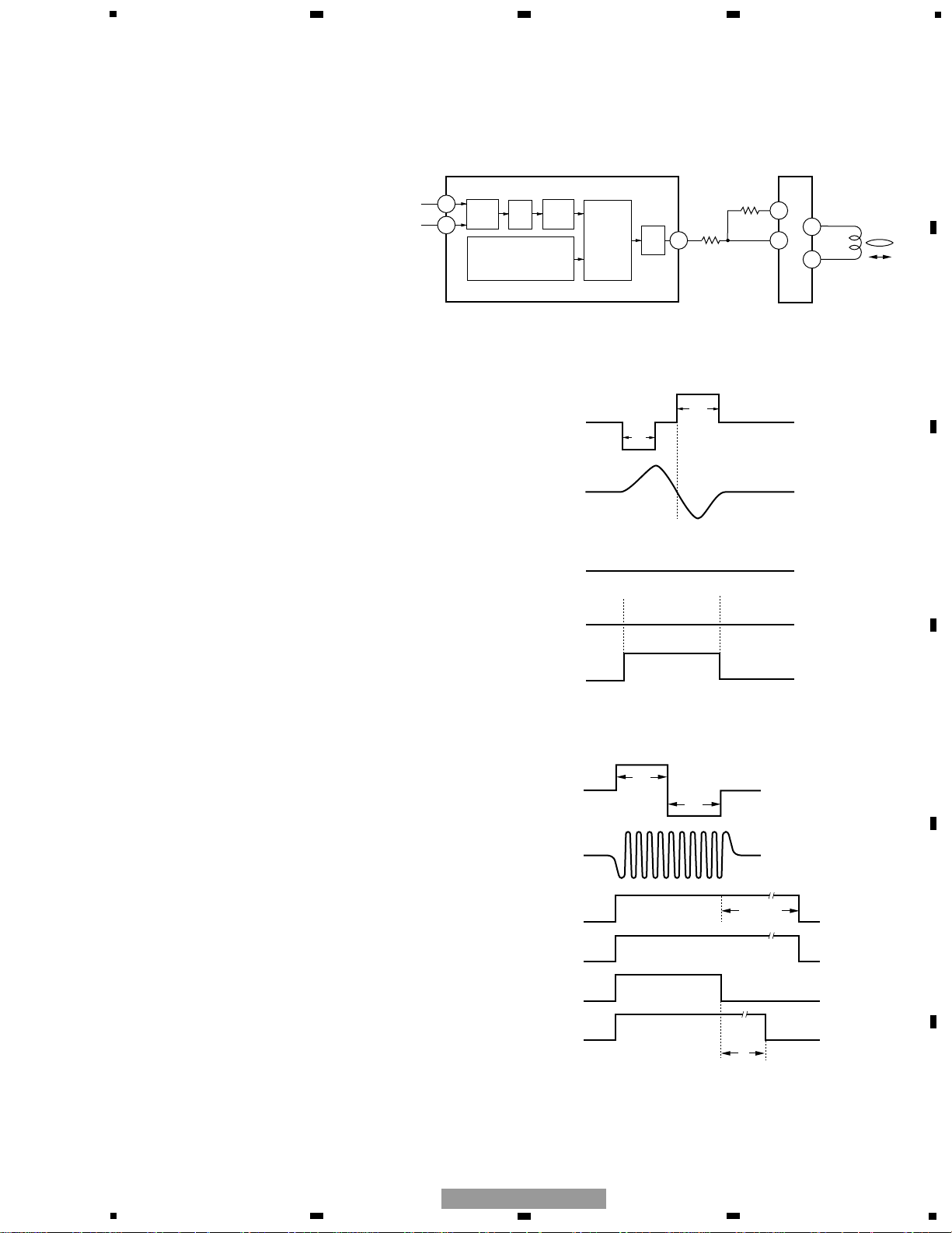
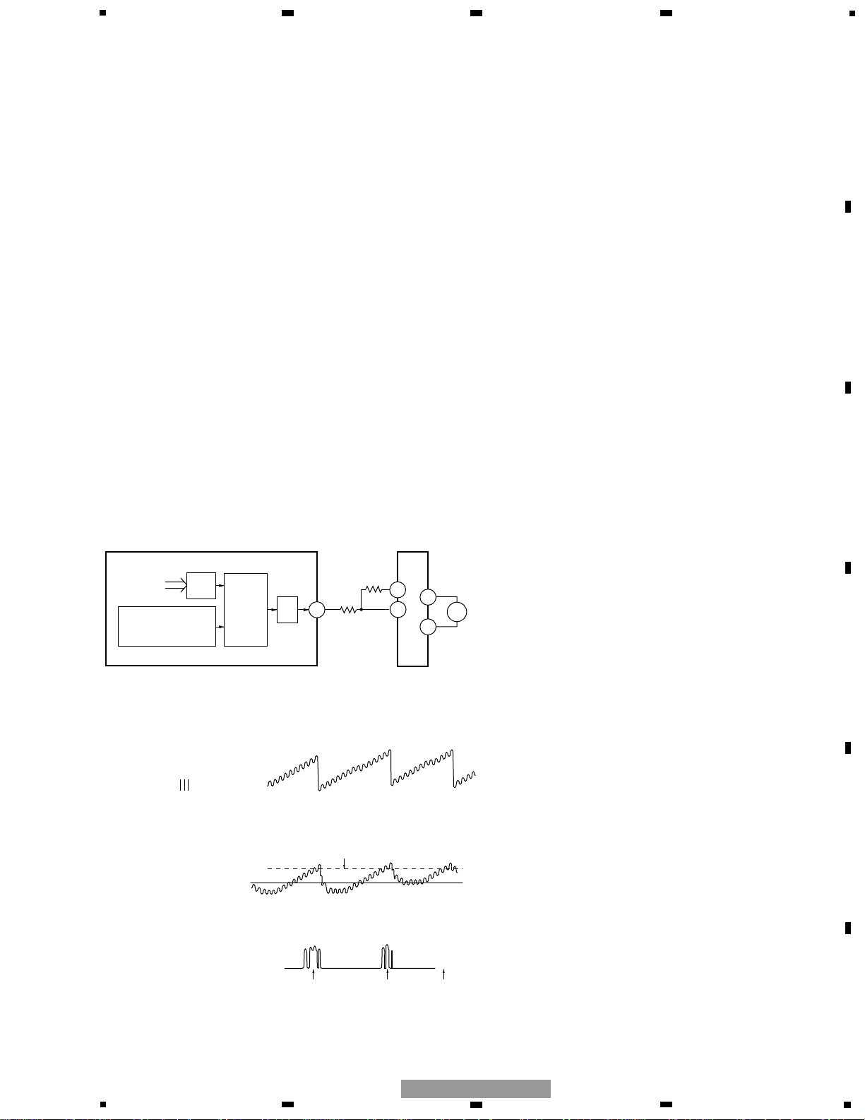
3) Carriage Servo System
The carriage servo supplies the tracking equalizer’s
low-frequency component (lens position data) output to
the carriage equalizer, then, after providing a fixed
amount of gain to it, outputs the drive signal from the
LSI. This signal is then applied to the carriage motor via
the driver IC.
When the lens offset reaches a certain level during play,
the entire pickup must be moved into the forward
direction. Therefore, the equalizer gain is set to the
level that allows to generate a voltage higher than the
carriage motor starting voltage. In actual operations, a
certain threshold level is set for the equalizer output by
the servo LSI so that the drive voltage may be output
from the servo LSI only when the equalizer output
exceeds the threshold level. This arrangement helps
reducing power consumption. Also, due to disc
eccentricity or other factors, the equalizer output may
cross the threshold level a number of times. In this
case, the drive voltage output from the LSI will have
pulse-like waveform.
DIG.
EQ
SD
COP
COM
IC301
BD7962FM
CARRIAGE
MOTOR
IC201 UPD63711GC
64 32
19
20
KICK, BRAKE
REGISTERS
DAC
CONTROL
FROM
TRACK. EQ
M
R318
10K
R316
15K
33
DRIVE ON/OFF THRESHOLD
CARRIAGE MOVED AT THESE POINTS
TRACKING DRIVE
(LOW FREQUENCY)
LENS POSITION
CRG DRIVE
(INSIDE UPD63711GC)
CRG MOTOR VOLTAGE
Fig.16 : CARRIAGE SERVO BLOCK DIAGRAM
Fig.17 : CARRIAGE SIGNAL WAVEFORM
Page 12

12
1
234
12
34
F
E
D
C
B
A
CX-951
4) Spindle Servo System
1. Simple FG servo:
This servo is to keep the disc rotation stable around
the appropriate speed.
The microcomputer monitors the FG signal, which
generates pulses depending
on the spindle motor rotation, to control the spindle
motor drive voltage.
This mode is used under the following conditions:
a) At setup, for the period from power on, focus close to
rough servo mode.
b) After focus is unlocked during play and until it is
locked again.
2. Applicable servo :
The CLV servo mode is turned on for the normal
operations.
In the EFM demodulation block, the frame sync
signal and internal counter output signal are
sampled for every WFCK/16 and a signal is produced
for indicating whether or not they are matching.
They are determined to be asynchronous only when
this signal fails to match 8 times in succession. In all
other cases, above two signals are assumed to be
synchronous. In the applicable servo mode, the
retracting servo is automatically selected if the two
signals are synchronous. If not, the regular servo is
automatically selected.
3. Brake:
This mode is to stop the spindle motor.
The microcomputer monitors the FG pulse signal.
When the FG pulse interval
(speed) exceeds the prescribed level, the full brake
mode is selected. When
the speed slows down to that level or lower, the
brake level is decreased. At
last the spindle motor is stopped.
4. Stop :
This mode is used for powering on the system and
the eject operation. When this mode is turned on,
voltage across the spindle motor is 0V.
5. Rough servo :
This mode is used for when the carriage feed
(carriage mode for the long search, etc.) is turned on.
The linear speed is calculated from the EFM
waveform and high or low level is entered to the
spindle equalizer. In the test mode, this mode is also
used for the grating check.
Fig.18 : SPINDLE SERVO MOTOR BLOCK DIAGRAM
DSP
BLOCK
DIG.
EQ
MD
A3
A1
IC1
BA6849FM
SPINDLE
MOTOR
IC201 UPD63711GC
65
19
2
5
DAC
EFM
SIGNAL
M
SPEED ERROR SIGNAL
PHASE ERROR SIGNAL
R317
10K
27
26
R315
15K
40
EC
IC301
BD7962FM
39
44
43
ECR
CONT
FG
3
A2
18
20
21
Page 13

13
5
6
7
8
5
6
7
8
F
E
D
C
B
A
CX-951
Every circuit adjustment on the CD-LSI of this system is
automated.
Every circuit adjustment is automatically implemented
when the disc is inserted or the CD mode is selected
from the source key. The following describes how the
adjustments are executed.
1) FZD Cancel Setting
This setting is used for executing the focus close
operation without fail.
When power is turned on, the FE offset level is read and
a voltage opposite to this offset value is written to the
CRAM on the IC to cancel the offset. In this manner, the
FZD threshold level can be set to a constant value
(+240mV), thereby ensuring to meet one of the
requirements for the IC to execute the focus close that
“the FZD signal is latched at high”.
2) Automatic Adjustment of TE, FE and RF Offset
Using REFO as the reference, this function adjusts the
pre-amp TE, FE and RF offsets to the respective target
value when power is turned on (targets values of the
TE, FE and RF are 0, 0 and −1V, respectively).
The following is the adjustment procedure :
(1) Respective offset (LD off) is read by the
microcomputer via the servo LSI.
(2) The microcomputer calculates the voltages to be
corrected from the read values, then sets them to
the specified field.
3) Automatic Adjustment of Tracking Balance (T.
BAL)
This adjustment is used for eliminating differences
between the pickup E and F channels outputs by
adjusting gain of the amplifier on the LSI. In the actual
operation, the TE waveform is adjusted so that it may
be vertically symmetric with REFO.
The following is the adjustment procedure :
(1) Make sure the focus close is complete.
(2) Kick the lens in the radial direction to generate the
TE waveform.
(3) At this time, the microcomputer reads the TE signal
offset value (via the servo LSI) being calculated by
the LSI.
(4) The microcomputer determines if the read offset
value is positive, negative or zero.
If the offset value =0, the adjustment is terminated.
If the offset value =A positive or negative value,
gain of the E and F channels amplifiers are modified
according the predetermined rule.
Then above steps (2) through (4) are repeated until the
“Offset value =0” or “Specified limit count” is reached.
4) Automatic Adjustment of FE Bias
This adjustment is intended at maximizing the RFI level
by optimizing the focus point in-play. This adjustment
utilizes the phase difference between the RF waveform
3T level and the focus error signal when disturbance is
applied.
Since disturbance is applied to the focus loop, this
adjustment is designed to take place in the same timing
as the auto gain control (to be described later).
The following is the adjustment procedure :
(1) Disturbance is injected to the focus loop by the
command from the microcomputer (within the servo
LSI).
(2) The LSI detects fluctuation of the RF signal 3T
component level.
(3) The LSI determines relationship between fluctuation
of the 3T component and the injected disturbance to
detect magnitude and direction of the off-focus
introduced.
(4) The microcomputer reads the detected results from
the LSI.
(5) The microcomputer calculates necessary correction,
then hands the calculated value to the bias
adjustment term set on the LSI.
This adjustment is repeated several times, as it is so
with the auto gain control, to ensure higher accuracy.
1.3 AUTOMATIC ADJUSTMENT FUNC- TIONS
Page 14

14
1
234
12
34
F
E
D
C
B
A
CX-951
5) Focus and Tracking Automatic Gain Control
This function is used for implementing automatic
control of the focus and tracking loop gain.
The following is the adjustment procedure :
(1) Inject disturbance to the servo loop.
(2) Extract the error signal (FE and TE) generated at
when the disturbance is applied to obtain the
signals G1 and G2 via the B.P.F.
(3) The microcomputer reads the G1 and G2 signals via
the LSI.
(4) Based on the necessary correction calculated by the
microcomputer, the LSI performs the loop gain
adjustment.
Above adjustments are repeated several times to
ensure higher adjustment accuracy.
6) Automatic RF Level Adjustment (RFAGC)
This adjustment is used for implementing intended
signal transmission successfully by adjusting
unevenness of the RF signal (RFO) levels, that results
from disc and machine relevant factors, to a target
value. The adjustment is actually done by varying gain
of the amplifier provided between the RFI and RFO.
The following is the adjustment procedure :
(1) Using the command, the microcomputer reads the
output from the RF level detection circuit on the
servo LSI.
(2) Based on the read value, the microcomputer
calculates an amplifier gain that will produce the
target RFO level.
(3) The microcomputer sends the corresponding
command to the servo LSI so that the above gain
value may be set.
This adjustment takes place at the following timing :
• When the focus close alone is completed during the
setup process.
• Just before the setup is completed (just before the
play takes place).
• After the off-focus has been corrected during the play.
7) Adjustment of Pre-Amp Stage Gain
It is used for adjusting the entire RFAMP (FE, TE and RF
amplifiers) to +6dB or +12dB depending on given gain
level when reflected light from the disc is significantly
below the required level due to stained lens. This
phenomena can be noticed when playing back the CD-
RW.
The following is the adjustment procedure :
When reflected light from disc is judged to be
significantly below the required level during the setup,
set the entire RFAMP to +6dB or +12dB. In this case, if
the gain is modified, the setup have to be repeated
from the first step.
Through the adjustment, if you judged the play
becomes available by setting the entire RFAMP to +6dB,
+
6dB should be selected for the setup next time on.
See the figure below :
Play at +6dB increases due to stained lens or other reasons
(the typical gain is employed for the initial setup)
Time
Gain of entire RFAMP
+ 12dB
+ 6dB
TYP
Play the CD-RW with the gain being set to +12dB
Play is started with +6dB
judging the lens is stained
Fig.19 : CONCEPTUAL DIAGRAM OF PRE-AMP GAIN ADJUSTMENT
Page 15

15
5
6
7
8
5
6
7
8
F
E
D
C
B
A
CX-951
8) Initial Adjusting Values
All the automatic adjustments are implemented using
the previous adjustment values as the initial values
unless the microcomputer power (the backup power) is
not turned off (though there are some exceptions).
When the backup is turned off, automatic adjustment is
executed based on the initial values rather than the
previous adjustment values.
9) Displaying Coefficients After Adjustment
You can display and check results of some automatic
adjustments (FE and RF offset, FZD cancel and F / T /
RFAGC) from the test mode. The following coefficients
are displayed in each automatic adjustment :
(1) FE and RF offset and FZD cancel
Reference value =32 (The coefficient of 32 indicates
that no adjustment was required).
The results are displayed in multiples of
approximately 40 mV.
An example : When FZD cancel coefficient =35
35 −32 =3
3 ×40 mV =120 mV
Since the corrected value is
approximately +120 mV, the FE offset
before adjustment was −120 mV.
(2) F and T gain adjustment
Reference value =Focus/Tracking =20
A coefficient displayed indicates an amount of
adjustment conducted on the reference value.
An example : When AGC coefficient =40
40/20 =Overall gain has bee doubled
(+6dB). (The original loop gain of 1/2
has been doubled to have the targeted
overall gain.)
(3) RF level adjustment (RFAGC)
Reference value =8
Coefficient =9 to 15 ····· The direction in which the
RF level is increased (the
gain is increased).
Coefficient =7 to 0 ······· The direction in which the
RF level is decreased (the
gain is decreased).
Incrementing or decreasing the coefficient by “1”
varies the gain by 0.7 to 1dB.
Maximum gain =Typically +6.5dB. Coefficient at this
time is 15.
Minimum gain =Typically −6.0dB. Coefficient at this
time is 0.
Page 16

16
1
234
12
34
F
E
D
C
B
A
CX-951
1.4 POWER SUPPLY
The G2 core unit requires the following two lines of
external power supply:
[VD 9V]
This is the power supply for mechanical servos. It is
applied directly to the driver and used to generate 5V
and 3.3V inside the regulator.
[VDD 5V]
This is the power supply for the microcomputer. It is
supplied from the main unit when the backup (+B) is
connected. The pull-up resistor is connected to
SWDVDD, which is obtained through the VDD switching
circuit.
There are two GND lines. One is the GND for the servo
and digital power supply, and the other is the audio
reference AGND. They are produced by separation
inside the core unit.
Fig.20 : POWER SUPPLY SECTION
VDCONT
VD circuit
System side
VD(9V)
5V Reg
CONTROL UNIT
IC303
PCB UNIT
(LED)
PCB UNIT
(M2 UNIT)
MUTE
Circuit
3+3ch
Driver
IC301
Disc
detection
LED
SPDL
Driver
PU UNIT
CD Control
IC201
LSI(CD DSP)
3.3V Reg
Memory
Contoroler
IC501 IC507
IC302
DRAM
VDD
IC201
SWDVDD
Laser
Diode
switching
ADENA
VDD circuit
Power supply
CD contorol
micro
computer
Pull up resistor
Page 17

17
5
6
7
8
5
6
7
8
F
E
D
C
B
A
CX-951
1.5 STS CIRCUIT
Sure Track System (STS) circuit temporarily keeps the
audio data read out from a CD in the memory. If the
pickup should come off the track, the data recorded in
the memory may be output and reproduced. This could
help avoid intermittent sound.
16M DRAM/IC507
MSM51V17400F6T FT
Analog Audio
3.3V system
CD5V
3V
CD LSI
(RF Amp./Servo DS P/
Signal Processor/
Audio DAC/LPF)
IC201
UPD63711GC
3.3V -> 5V
Converter
IC504
TC74VHCT08AFT
Digital
Compression
IC503
PD4501B
Shock proof
memory
controler
IC501
SM5903BFP
5V -> 3.3V
Converter
IC505
TC74VHC541FT
Compact Disc
5V system
CD3V
Data Read
(x 2 Speed)
Double Rate
Single Rate
Playback
(x1 Speed)
DAC+LPF
The STS circuit is controlled by the shockproof memory
controller (SM5903BFP). The audio signal is read out
from a CD at X2 speed, demodulated in the CD LSI, and
supplied to the shockproof memory controller. This
memory controller temporarily memorizes the audio
data in the DRAM, reads out the data, and outputs to
the DAC at X1 speed using the master clock (MCK:
16.93MHz), which is supplied from the CD LSI, as the
reference clock.
The written speed is higher than the DRAM read-out
speed. When the DRAM memory becomes full, the
controller stops writing the data like in the pause mode,
but continues reading out the recorded data from the
memory. When some vacant area appears in the
memory, the controller starts writing the data again.
(The RAM remaining memory is monitored at the
STSMO terminal.)
Repeated operations of the above process have realized
efficient use of the DRAM and about 10.7-second data
memorization. Therefore, even when the pickup should
remain on the off-track state for 10 seconds due to
external shocks, this STS circuit will reproduce the
audio data without intermittent sound.
Operating principles
Page 18

18
1
234
12
34
F
E
D
C
B
A
CX-951
In the loading mode: LOP<LOM, LO1; L, LO2; H
In the ejection mode: LOP>LOM, LO1; H, LO2; L
Drive voltages (LOCONT ; H) ; 6.5V
(LOCONT ; L) ; 4.4V
1.6 Mechanism control section
Outline
The movement of the changer mechanism module is
realized by sophisticated combinations of the
LOAD/EJECT, ELEVATION, CAMGEAR motor (in the
operation mode), and SPDL CLAMP operations.
1) Loading
1.1) Detection control
This mechanism module employs the following three
detection systems:
1.2) Drive control
The control unit controls the loading motor to load and
eject a disc.
a. Drive circuit
The drive circuit controls the driving direction and the
two drive voltages by using the LO1 and LO2, and the
LOCONT (H/L) respectively, which are output from the
microcomputer (IC702).
Function Sensor Descriptions
LOAD/EJECT detection Phototransistors (Q1, Q22) and LEDs (D31, D32)
To watch the starting of loading and disc ejection
12-cm disc detection Two switches (S21, 22) To sense the disc size
Loading completion One switch (S41)
Q21,22
S21,22
S41
LOADPHT
LOADSW1
LOADSW2
IC702
89
81
MECHANISM
CONTROLLER
82
37
76
75
LO1
LO2
IC301
30
DRIVER
31
3+3ch
24
21
22
LOP
LOADING
MOTOR
LOM
LOCONT
EVREF2
Page 19

19
5
6
7
8
5
6
7
8
F
E
D
C
B
A
CX-951
b. Drive control sequence
In the loading:
1 When the LOADPHT is turned ON (H), the drive operation starts.
4 When the ON state of the LOADSW2 is sensed, the loading motor stops.
In the ejection mode:
After the loading motor starts moving 1, the OFF state of the LOADSW1 is
sensed 3, then the loading motor stops 16msec after the counterelectromotive
brake is applied.
2) Elevation
2.1) Detection control
By using the linear position sensor (VR1), the data on the height of the stage
chassis is obtained and converted in voltage, then applied to the A/D converter
in the microcomputer to detect the absolute position.
2.2) Drive control
The control unit controls the ELV motor to perform the following operations:
• To open and close the shutter
• To open and close the tray claws (in the loading mode)
• Elevation
• To open the shutter (option)
LOADPHT
LOADSW1
LOADSW2
12
3
LOADPHT
LOADSW1
LOADSW2
1
32
4
ADVREF(EVREF)
VR11
EREF
GND
ELVSENS
Linear position sensor
VR1
Detection circuit
Page 20

20
1
234
12
34
F
E
D
C
B
A
CX-951
a. Drive circuit
The drive circuit controls the driving direction and the
two drive voltages by using the ELV1 and ELV2, and the
ELVCONT (H/L) respectively, which are output from the
microcomputer (IC702).
b. Drive control sequence
(1) The continuous driving mode is kept until the brake
starting position.
(2) When it is sensed that the brake starting position is
passed, the short brake starts.
(3) The pulse drive operation starts to move the stage
toward the OK range. When the stage comes into the
OK range and chatter is checked, the operation ends.
3) CAM motor
3.1) Detection control
The three switches CAMEOK (S32), CAMLOAD (S31)
and CAMCLMP (S11) detect the following four positions
where the CAM operation needs to stop: EOK: Tray
changing allowable position LIFT: Load/eject allowable
position CLMP: The allowable position to change the
used claws from the TRAY claws to the SPDL claws
PLAY: PLAY allowable position.
3.2) Drive control
The control unit controls the CAM motor to perform the
following operations:
• Trays separation
• CRG chassis rotation (to move to the PLAY position)
• Mechanical lock release
• Tray claws (for disc clamp) open/close (in the PLAY
mode)
a. Drive circuit
The drive circuit controls the driving direction by using
the CG1 and CG2, which are output from the
microcomputer (IC702).
To move the CRG chassis in the outer direction:
CGP<CGM, CG1; H, CG2; L
To move the CRG chassis in the inner direction:
CGP>CGM, CG1; L, CG2; H
Drive voltage: 7.4V fixed
To drive in the UP direction:ELP<ELM, ELV1; H, ELV2; L
To drive in the DOWN direction:
ELP>ELM, ELV1; L, ELV2; H
Drive voltages
(LOCONT: H) 7.4V --- Used in the continuous driving mode
(LOCONT: L) 6.3V --- Used in the pulse drive mode
(around the targetposition)
VR1
VR11
ELVSNS
EREF
IC702
91
92
MECHANISM
CONTROLLER
78
77
ELV1
ELV2
53
IC301
4
DRIVER
5
3+3ch
8
ELP
2
ELEVATION
MOTOR
3
ELM
ELVCONT
EVREF2
Page 21

21
5
6
7
8
5
6
7
8
F
E
D
C
B
A
CX-951
S32
IC702
EVREF2
CAMEOK
CAMLOAD
CG1
CGP
CAMGEAR
MOTOR
CGM
CG2
CAMCLMP
MECHANISM
CONTROLLER
21
22
23
87
86
IC301
3+3ch
DRIVER
7
6
34
8
35
S31
S11
S1
IC201
HOME
CLAMP
SD
COP
CARRIAGE
MOTOR
COM
REFO
CD
CONTROL
64
IC702
MECHANISM
CONTROLLER
79
72
64
IC301
3+3ch
DRIVER
32
36
20
19
S2
4) SPDL clamp
4.1) Detection control
In the detection circuit, the following two switches are
used:
HOME switch (S1) for the servos
CLAMP switch (S2) for claw closing confirmation
4.2) Drive control
The drive circuit moves the CRG toward inner tracks
than those for the normal play, and operates the disc
clamp mechanism.
Drive circuit
Claw open (close) drive voltage: 5.0V
Retry drive voltage: 7.0V
Page 22

22
1
234
12
34
F
E
D
C
B
A
CX-951
Mechanical positions
Disc1
(6F)
Disc2
(5F)
ELV position LIFT position CLAMP position
ELV UP
(DISCSEL)
ELV DN
(DISCSEL)
ELV position LIFT position CLAMP position
Load/eject position
(Door Open)
ELV UP
(LIFTUP)
CAM FWD
(ELVOUT)
CAM REV
(ELVIN)
Load/eject position
(Door Open)
ELV UP
(LIFTUP)
CAM FWD
(ELVOUT)
CAM REV
(ELVIN)
ELV DN
(LIFTDN)
ELV DN
(LIFTDN)
CAM FWD
(CRGIN)
CAM REV
(CRGOUT)
The claws close
CAM FWD
(CRGIN)
CAM REV
(CRGOUT)
The claws close
CAM FWD
(TRYDN)
CAM REV
(TRYUP)
The claws open
CAM FWD
(TRYDN)
CAM REV
(TRYUP)
The claws open
PLAY position
PLAY position
ELV UP
(DISCSEL)
Disc3
(4F)
ELV position LIFT position CLAMP position PLAY position
ELV UP
(DISCSEL)
Disc6
(1F)
ELV position LIFT position CLAMP position PLAY position
ELV DN
(DISCSEL)
ELV DN
(DISCSEL)
Load/eject position
(Door Open)
ELV UP
(LIFTUP)
CAM FWD
(ELVOUT)
CAM REV
(ELVIN)
Load/eject position
ELV UP
(LIFTUP)
CAM FWD
(ELVOUT)
CAM REV
(ELVIN)
(LIFTDN)
(Door Open)
(LIFTDN)
ELV DN
ELV DN
CAM FWD
(CRGIN)
CAM REV
(CRGOUT)
The claws close
CAM FWD
(CRGIN)
CAM REV
(CRGOUT)
The claws close
CAM FWD
(TRYDN)
CAM REV
(TRYUP)
The claws open
CAM FWD
(TRYDN)
CAM REV
(TRYUP)
The claws open
Page 23

23
5
6
7
8
5
6
7
8
F
E
D
C
B
A
CX-951
CAM operation
TRYDN
(From CLMP position to PLAY position or CAMLOAD ON)
CAM OK
CAM LOAD
CAM CLMP
CAM MOTOR
(CGP-CGM)
CIN_EXP
(From EOK position to CLMP position or CAMCLMP ON)
CAM OK
CAM LOAD
CAM CLMP
TRYUP
(From PLAY position to CLMP position or CAMCLMP OFF to ON)
CAM OK
CAM LOAD
CAM CLMP
CAM MOTOR
(CGP-CGM)
EIN-EXP
(From CLMP position to EOK position or CAMEOK ON)
CAM OK
CAM LOAD
CAM CLMP
CAM MOTOR
(CGP-CGM)
CRGIN
(From LIFT position to CLMP position or CAMCLMP ON)
CAM OK
CAM LOAD
CAM CLMP
CAM MOTOR
(CGP-CGM)
ELVOUT
(From EOK position to LIFT position or CAMLOAD OFF to ON)
CAM OK
CAM MOTOR
(CGP-CGM)
CRGOUT
(From CLMP position to LIFT position or CAMLOAD ON)
CAM OK
CAM LOAD
CAM CLMP
CAM MOTOR
(CGP-CGM)
ELVIN
(From LIFT position to EOK position or CAMEOK ON)
CAM OK
CAM LOAD
CAM CLMP
CAM MOTOR
(CGP-CGM)
CAM LOAD
CAM CLMP
CAM MOTOR
(CGP-CGM)
Page 24

24
1
234
12
34
F
E
D
C
B
A
CX-951
ELV operation
DISCSEL
EVREF
ELV SNS
ELV MOTOR
(ELM-ELP)
CG MOTOR
(CGP-CGM)
LIFTUP
LOAD PHT
ELV SNS
ELV MOTOR
(ELM-ELP)
LOAD SW2
DISC LOAD (with no disc loaded in a tray)
LIFTUP completion
LOAD PHT
ELV SNS
ELV MOTOR
(ELM-ELP)
LOAD SW2
for DISC EJCT(with a disc loaded in a tray)
LIFTUP completion
The waveform shows the
changes in the EJECT mode.
OFF (with no disc sensed)
CLAMP operation
DSKFREE
CRG MOTOR
(COP-COM)
CAM MOTOR
(CGP-CGM)
LOAD/EJECT operation
LOAD
LOAD PHT
LOAD SW1
LOAD SW2
Until CLMP ON (The drive voltage drops with HOME ON.)
CLMP
HOME
From LOADPHT H (disc insertion starts) to LOADSW2 ON
DSKLOCK
Until HOME OFF
CLMP
HOME
CRG MOTOR
(COP-COM)
CAM MOTOR
(CGP-CGM)
EJCT
From the starting of the loading motor to LOADSW1 ON _ OFF
LOAD PHT
LOAD SW1
LOAD SW2
ON (with a disc sensed)
LOADING
(LOM-LOP)
The waveform shows the
changes in the LIFTDN mode.
LOADING MOTOR
(LOM-LOP)
The waveform shows the
changes in the LIFTUP mode
Counterelectromotive brake
Page 25

25
5
6
7
8
5
6
7
8
F
E
D
C
B
A
CX-951
2. MECHANISM DESCRIPTIONS
1) Initialization
When the power is turned on, the mechanism starts the
initializing operation to check on which trays a disc is
loaded.
<Initialization operations> (From the transport position)
• The tray holder lock is reset.
• During elevation, it is sensed if or not a disc is loaded
on each of the trays from DISC #6 (1F) to DISC #1 in
turn with the LOAD3 switch (S41: Load completion SW).
(On the whole product, the DISC #1 button is used to
select the uppermost floor (6F) tray, which is different
from that for the G1-series mechanism.)
• When the above disc sense ends, elevation starts to
clamp a disc. If there is no tray with a disc loaded, the
mechanism will not proceed to the elevation mode for
the disc clamp operation.
• To clamp the loaded disc, the cam gear motor rotates
to move the carriage mechanism. (It is the same with
no disc loaded.)
• After the disc is clamped, the mechanism stops.
If the CD source is selected, the spindle motor starts
rotating to play the disc.
In other words, when the power is turned on for the
first time, the mechanism will get into the quasiclamping mode for the DISC #1 and stop.
2) Functions of motors, switches and sensors
Loading motor Disc loading
Disc ejection
Cam gear motor Tray separation
Carriage mechanism assy rotation
Mechanical lock release
Tray claws open/close (in the play mode)
Elevation motor Shutter open/close
Tray claws open/close (in the loading mode)
Elevation
Door open (option)
Carriage motor Search
Disc clamp
Spindle motor Disc rotation
Page 26

26
1
234
12
34
F
E
D
C
B
A
CX-951
3) Loading
The mechanism has realized the disc detection by
employing two switches and two phototransistors
mounted on the PCB UNIT (LOAD), and one switch
mounted on the PCB UNIT.
a. Switches LOAD1 and LOAD2 (S21, S22) (Signal:
LOADSW1)
The switches mounted on the PCB UNIT (LOAD) turn on
when the left and right DISC detection levers are moved
by the loaded disc. These two switches LOAD1 and
LOAD2 are connected in series to produce the same
signal. Only when both of them turn on, the signal
LOADSW1 is switched from high to low.
b. Phototransistors (Q21, Q22) (Signal: LOADPHT)
The phototransistors receive the beams emitted by the
LEDs (D31 and D32) and sense if the beams are
interrupted. These two phototransistors Q21 and Q22
are connected in series to make the same signal. Only
when both of them are covered from the beams, the
signal LOADPHT is switched from high to low.
c. Switch LOAD3 (S41) (Signal: LOADSW2)
When the loaded disc reaches the stop position, the
switch S41 (mounted on the PCB UNIT) is pushed by
the LOAD completion SW arm on the stage. This
switch detects discs in the initializing mode, and senses
that the disc is inserted into the bottom.
LOAD3 Switch(S41)
LOAD Completion
SW Arm
LOADING Motor
LOAD1
Switch(S21)
LOAD2 Switch(S22)
DISC Detection
Lever
Phototransistors
(Q21, Q22)
DISC Detection
Lever
Page 27

27
5
6
7
8
5
6
7
8
F
E
D
C
B
A
CX-951
<Loading operations>
When the disc covers the phototransistors and the
LOADPHT signal is switched from high to low, the
loading motor rotates in the disc draw-in direction.
Then the mechanism continues drawing in the disc
watching the signal from the phototransistors. When
the signal is switched from low to high (or around the
center hole of a 12cm disc), the mechanism confirms
that the signal from the switches LOAD1 and LOAD2
has been switched from high to low. If the signal
remains high, the mechanism will eject the disc
forcedly. Only when the signal has been switched to
low, the disc draw-in operation continues.
The disc pushes the LOAD completion SW arm, the
LOAD3 switch turns on, and the LOADSW2 signal
switches from high to low. Then the loading operation
completes.
<Eject operations>
After the eject operation starts, the signal from the
switches LOAD1 and LOAD2 changes from high to low,
then returns to high. At this moment, the mechanism
uses the brake function to stop the loading motor.
4) Cam gear motor
a. Tray clamp (tray separation) mechanism
There are the following five positions in the tray height
(separation) states:
1. (Tray free) ELVok: The plate cams do not clamp the
tray.
2. (Clamp) Load: The plate cams clamp the tray at the
loading position
3. (Clamp) CRGIN: The plate cams clamp the tray at the
position where the carriage moves in. (The upper
dead point)
4. (Clamp) Disc clamp: The plate cams clamp the tray at
the position where a loaded disc can be clamped (or a
loaded disc on the tray stays on the support wheel).
5. (Clamp) Play: The plate cams clamp the tray at the
disc play position (where there is some clearance
under the disc).
12cm
S41
Hi
Lo
Hi
Lo
Hi
Lo
Q21,22
S21,22
LOAD
8cm
Q21,22
S21,22
S41
Loading
operation
start
Hi
Lo
Hi
Lo
Hi
Lo
EJ
stop
position
LOAD
EJECT
Loading
operation
start
Eject
the disc forcedly
EJECT
Loading operation completes
Page 28

28
1
234
12
34
F
E
D
C
B
A
CX-951
Carriage Rotation Arm
Carriage Rotation
Arm Shaft
Tray
Clamper Lever
Cam Gear
Motor
Mode Switch
Lever
Carriage Rotation Lever
Groove for
Carriage Rotation Lever
Groove for
Tray Clamper Lever
Plate Cam
<Tray separation driving principles> for real operations
The right and left plate cams with cam grooves synchronize
the back and forth movement to change the height of the
tray.One plate cam has two grooves, one is in the front side,
and the other is in the rear side. The front and rear grooves
have the same shape except for the load portion.
These plate cams are fixed on the left and right sides of the
stage chassis. To minimize the height of the plate cams, the
cam grooves in the stage are used. A sophisticated
combination of a plate cam groove and a stage groove
realizes the tray's movement in the up and down direction.
<Tray separation driving principles> for driving power
The driving power comes from the cam gear motor. The
torque decelerated by the gears is transferred to the cam
gear. The cam gear has four grooves. One of them is to
drive the tray clamper lever. In accordance with this cam
groove, the tray clamper lever moves back and forth. There
are two long grooves at the tray clamper lever's ends. The
plate cam's shafts are engaged with these grooves.
Therefore, The tray clamp lever's movement in the back and
forth direction is transferred to the plate cams by these
grooves and the shafts.
The position of the tray pin above
the plate cam changes as shown below:
5 4 3 2 1
The movement of the tray pin indicates the
movement of the plate cams.
The pin of the tray right above the plate cam:
:
It moves up and down together with the plate cam.
:
The pin of the target tray:
It moves up and down together with the plate cam.
:
For the pin of the tray right under the plate cam:
The above figure is just for reference.
The plate cam moves up and down for itself.
Page 29

29
5
6
7
8
5
6
7
8
F
E
D
C
B
A
CX-951
b. Carriage mech assy rotation mechanism
The carriage mech assy rotation mechanism is to move
the carriage mech assy into the disc area for disc
reproduction. The driving power from the cam gear is
transferred to the carriage rotation lever (as sliding
movement), then to the carriage rotation arm (as
rotation).
Carriage Mech Assy
Carriage Rotation Arm
Page 30

30
1
234
12
34
F
E
D
C
B
A
CX-951
5) Elevation motor
The elevation motor is used for the following two
operations:
1. Elevation up and down
2. Shutter open and close (to move roller and disc
guide, and to open or close the tray claws)
a. The elevation motor rotation slides the ELV stair
slides via the gears.
b. The ELV reverse arm (located on the mechanism
bottom side) synchronizes the left and right ELV
stairs.
c. The linear position sensor (VR1) detects the height of
the elevation.
6) Carriage motor
The carriage motor torque decelerated by the first belt
is transferred via some gears. The last gear is engaged
with the gear inserted into the feed screw. The feed
screw is engaged with the rack of the PU unit, which
moves the PU unit at last.
When the PU unit moves to inner tracks than the home
position, the disc clamp claws start to close. When the
claws are open, the plate of the spindle motor support
wheel is pressing the claws to hold them in the open
position. When the PU rack and the arm move to close
the claws, the plate will be lowered and the claws will
be set inside the support wheel. This is the disc clamp
claw close mode.
Linear Position Sensor (VR1)
ELV Reverse Arm
Elevation Motor
ELV Stair
ELV Stair
Page 31

31
5
6
7
8
5
6
7
8
F
E
D
C
B
A
CX-951
PU Unit
Support Wheel
Disc Clamp
Claw
Rack
Arm
Arm
Carriage Motor
Rack
Home Switch
Spindle Motor
Clamp Switch
Page 32

32
1
234
12
34
F
E
D
C
B
A
CX-951
3. DISASSEMBLY
- Removing the Holder Unit
1. Set the whole mechanism to the loading mode.
2. Unhook the four springs of the Holder Unit and
temporarily hook them at the frames as shown in the
right figure.
3. Lift up the Holder Unit straight and remove it.
- Removing the PU Unit(PX1)
1. Set the mechanism to the shipment mode.
2. Remove the two screws A and two screws B.
3. Remove the Frame.
4. Apply shorting solder to the PU flexible cable before
disconnecting it from the connector CN12.
5. Disconnect the flexible cable from the connector CN12,
and remove the flexible cable Holder.
6. Remove the washer and Arm. (Be careful not to lose
the spring B.)
7. Remove the screw, spring A, and Collar.
8. Remove the Carriage Mech. Assy.
Page 33

33
5
6
7
8
5
6
7
8
F
E
D
C
B
A
CX-951
9. Apply shorting solder to the PU flexible cable before
disconnecting it from the Connector.
10. Disconnect the PU flexible cable from the
Connector.
11. Move the PU Unit to the left side slightly by turning
the Gear.
12. Pull out the spindle motor Support Wheel Unit
upwards to remove it.
13. Remove the Spring.
14. Slide the holder to make it easier to remove the
Screw Unit.
15. While pressing the shaft holder in the direction
shown by the black arrow in the right figure, remove
the PU Unit together with the Screw Unit.
Note:
To assemble the PU Unit, insert the Spring on the PU
rear between the PU Unit and the Guide first.
- Removing the Load Motor Assy
1. Remove the four screws.
2. Disconnect the Load Motor connector from the
connector CN13.
3. Remove the Loading Mech. Assy.
4. Remove the washer and spring.
5. Remove the Roller.
Page 34

34
1
234
12
34
F
E
D
C
B
A
CX-951
6. Remove the Arm and Holder.
7. Remove the screw and Load Motor Assy.
- Removing the Cam Motor Assy and ELV Motor
Assy
1. Remove the connector from the Connector CN14.
2. Remove the Cover.
3. Remove the screw A and the Cam Motor Assy.
4. Remove the screw B and the ELV Motor Assy.
 Loading...