

Pioneer CTW-208-R Service manual
Ωı¿ˆ<?˘B
DECK
Î
DECK I
+
REV
PLAY
LEFT
MS
LEVEL
RIGHT
—
3
COPY I II
NORMAL HIGH
POWER
I
— OFF _ ON
DECK II
DECK IIDECK I
+
COPY
FWD
PLAY
REV
REC
FWD
-00
DOLBY NR
OFFBC
MS
dB
-15
-9 -3
-3
0
Ÿ
—
DECK II
REV MODE
RELAY/SKIP
HIGH SPEED
COPY SYSYEM
MIN MAX
AUTO REVERSE
HIGH SPEED COOPY SYSTEM / REC & PLAY
REC
LEVEL
DECK
II
DOLBY B-C NR
STEREO DOUBLE CASSETTE DECK
AUTO REVERSE
Auto Tape Selector Auto Tape Selector
HIGH SPEED COOPY SYSTEM / PLAYBACK
STEREO DOUBLE CASSETTE DECK
CT-W208R
THIS MANUAL IS APPLICABLE TO THE FOLLOWING MODEL(S) AND TYPE(S).
Type
KUXJ AC120V
KCXJ AC120V
HYXJ AC220-230V
HVXJ AC230-240V
Model
CT-W208R
Power Requirement
Remarks
ORDER NO.
RRV2186
CONTENTS
1. SAFETY INFORMATION
2. EXPLODED VIEWS AND PARTS LIST
3. BLOCK DIAGRAM AND SCHEMATIC DIAGRAM..10
4. PCB CONNECTION DIAGRAM
5. PCB PARTS LIST
6. ADJUSTMENT
...............................................
....................................................
PIONEER CORPORATION 4-1, Meguro 1-chome, Meguro-ku, Tokyo 153-8654, Japan
PIONEER ELECTRONICS SERVICE, INC. P.O. Box 1760, Long Beach, CA 90801-1760, U.S.A.
PIONEER ELECTRONIC (EUROPE) N.V. Haven 1087, Keetberglaan 1, 9120 Melsele, Belgium
PIONEER ELECTRONICS ASIACENTRE PTE. LTD. 253 Alexandra Road, #04-01, Singapore 159936
c
PIONEER CORPORATION 1999
......................................
................
..........................
18
24
27
2
3
7. GENERAL INFORMATION
7.1 DIAGNOSIS
.................................................
7.1.1 POWER ON SEQUENCE
7.2 PARTS
7.2.1 IC
.........................................................
............................................................
8. PANEL FACILITIES AND SPECIFICATIONS
................................
31
31
......................
31
32
32
....
33
T–ZZR AUG. 1999 Printed in Japan
CT-W208R
1. SAFETY INFORMATION
This service manual is intended for qualified service technicians ; it is not meant for the casual do-ityourselfer. Qualified technicians have the necessary test equipment and tools, and have been trained
to properly and safely repair complex products such as those covered by this manual.
Improperly performed repairs can adversely affect the safety and reliability of the product and may
void the warranty. If you are not qualified to perform the repair of this product properly and safely, you
should not risk trying to do so and refer the repair to a qualified service technician.
WARNING
This product contains lead in solder and certain electrical parts contain chemicals which are known to the state of California to cause
cancer, birth defects or other reproductive harm.
Health & Safety Code Section 25249.6 – Proposition 65
NOTICE
(FOR CANADIAN MODEL ONLY)
Fuse symbols (fast operating fuse) and/or (slow operating fuse) on PCB indicate that replacement parts must
be of identical designation.
REMARQUE
(POUR MODÈLE CANADIEN SEULEMENT)
Les symboles de fusible (fusible de type rapide) et/ou (fusible de type lent) sur CCI indiquent que les pièces
de remplacement doivent avoir la même désignation.
(FOR USA MODEL ONLY)
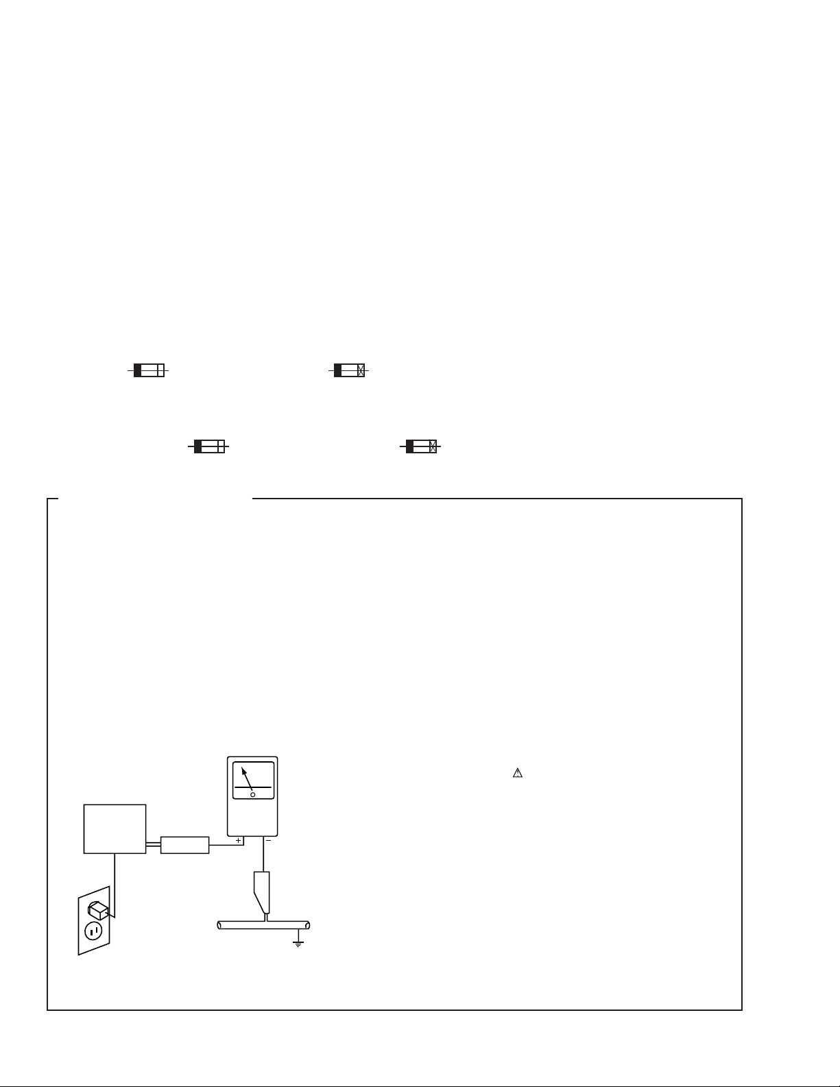
1. SAFETY PRECAUTIONS
The following check should be performed for the
continued protection of the customer and service
technician.
LEAKAGE CURRENT CHECK
Measure leakage current to a known earth ground (water
pipe, conduit, etc.) by connecting a leakage current tester
such as Simpson Model 229-2 or equivalent between the
earth ground and all exposed metal parts of the appliance
(input/output terminals, screwheads, metal overlays, control
shaft, etc.). Plug the AC line cord of the appliance directly
into a 120V AC 60Hz outlet and turn the AC power switch
on. Any current measured must not exceed 0.5mA.
Reading should
not be above
0.5mA
Earth
ground
Device
under
test
Also test with
plug reversed
(Using AC adapter
plug as required)
Leakage
current
tester
Test all
exposed metal
surfaces
ANY MEASUREMENTS NOT WITHIN THE LIMITS
OUTLINED ABOVE ARE INDICATIVE OF A POTENTIAL
SHOCK HAZARD AND MUST BE CORRECTED BEFORE
RETURNING THE APPLIANCE TO THE CUSTOMER.
2. PRODUCT SAFETY NOTICE
Many electrical and mechanical parts in the appliance
have special safety related characteristics. These are
often not evident from visual inspection nor the protection
afforded by them necessarily can be obtained by using
replacement components rated for voltage, wattage, etc.
Replacement parts which have these special safety
characteristics are identified in this Service Manual.
Electrical components having such features are identified
by marking with a
in this Service Manual.
The use of a substitute replacement component which does
not have the same safety characteristics as the PIONEER
recommended replacement one, shown in the parts list in
this Service Manual, may create shock, fire, or other hazards.
Product Safety is continuously under review and new
instructions are issued from time to time. For the latest
information, always consult the current PIONEER Service
Manual. A subscription to, or additional copies of, PIONEER
Service Manual may be obtained at a nominal charge from
PIONEER.
on the schematics and on the parts list
AC Leakage Test
2
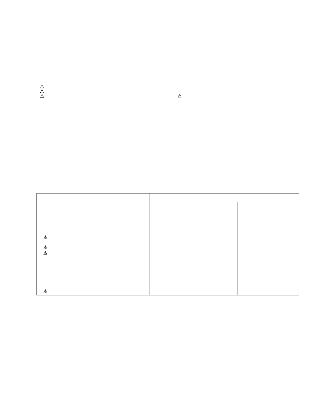
2. EXPLODED VIEWS AND PARTS LIST
NOTES:• Parts marked by "NSP" are generally unavailable because they are not in our Master Spare Parts List.
The mark found on some component parts indicates the importance of the safety factor of the part.
•
Therefore, when replacing, be sure to use parts of identical designation.
Screws adjacent to mark on the product are used for disassembly.
•
CT-W208R
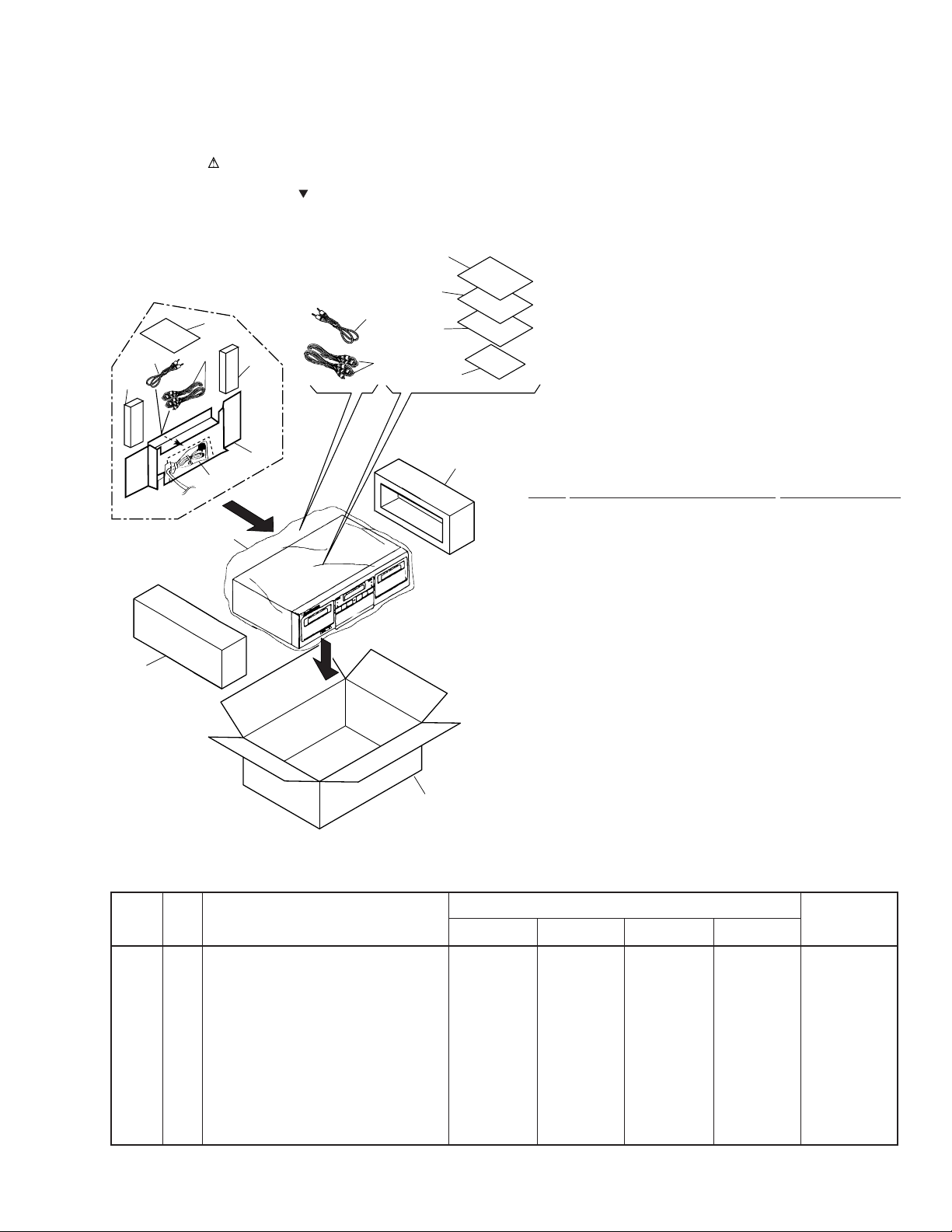
2.1 PACKING
14
5
11
HVXJ type Only
}
1
6
12
4
}
11
13
7 (KUXJ,
HVXJ types only)
8 (HYXJ
type only)
5
9 (HYXJ,
KCXJ
types only)
6
10
2
(1) PACKING PARTS LIST
Mark No. Description Part No.
1 Pad L RHA1115
2 Pad R RHA1116
3 Packing Case See Contrast table (2)
4 Mirror Mat Sheet Z23-007
(750x600x0.5)
5 Control Cable (L=1.0m) PDE1267
6 Connection cord with Pin-plug RDE1036
(L=1.0m)
7 Operating Instructions See Contrast table (2)
(English)
8 Operating Instructions See Contrast table (2)
/German/Italian)
NSP 10 Warranty Card See Contrast table (2)
(Spanish/Portuguese/Dutch/Swedish
9 Operating Instructions See Contrast table (2)
(English/French)
11 Spacer A See Contrast table (2)
12 Polyethylene Bag See Contrast table (2)
3
(115x270x0.05)
13 Spacer B See Contrast table (2)
14 Caution Card See Contrast table (2)
(2) CONTRAST TABLE
CT-W208R/KUXJ, KCXJ, HYXJ and HVXJ are constructed the same except for the following :
Mark
NSP 10 Warranty Card ARY7023 ARY7024 ARY7022 ARY7022
No.
3 Packing Case RHG1912 RHG1912 RHG1910 RHG1911
7 Operating Instructions (English) RRB1198 Not used Not used RRB1198
8 Operating Instructions Not used Not used RRD1218 Not used
9 Operating Instructions (English/French) Not used RRE1179 RRE1179 Not used
11 Spacer A Not used Not used Not used RHC1032
12 Polyethylene Bag (115X270X0.05) Not used Not used Not used Z21-013
13 Spacer B Not used Not used Not used RHC1033
14 Caution Card Not used Not used Not used RRN1001
Symbol and Description
(Spanish/Portuguese/Dutch/Swedish
/German/Italian)
KUXJ type KCXJ type HYXJ type HVXJ type
Part No.
Remarks
3

CT-W208R
2.2 EXTERIOR
19
27
27
27
27
20
KUXJ type Only
24
4
6
26
24
22
8
18
24
21
KUXJ and KCXJ
types Only
2
17
23
24
1(2/2)
24
29
9
11
27
27
27
27
24
C
16
C
24
13
13
7
5
10
1(1/2)
7
28
Fuse holder
HVXJ type Only
27
Refer to " 2.3 FRONT PANEL SECTION".
4
25
HVXJ and HYXJ
types Only
12
Except HVXJ and HYXJtypes
27
14
15
27
HVXJ and HYXJtypes Only
(1) EXTERIOR PARTS LIST
CT-W208R
Mark No. Description Part No.
1 MAIN UNIT See Contrast table (2)
NSP 2 POWER SWITCH UNIT See Contrast table (2)
3 • • • • •
NSP 4 Transformer 2 UNIT See Contrast table (2)
5 Cord Stopper See Contrast table (2)
6 Fuse (FU1, FU2, 1.25A) See Contrast table (2)
7 AC Power Cord See Contrast table (2)
8 Power Transformer See Contrast table (2)
9 PCB Mold AMR2533
NSP 10 Chassis RNB1144
11 Rear Panel See Contrast table (2)
12 Rubber Sheet See Contrast table (2)
NSP 13 PCB Spacer PNY–404
14 Foot Assy REC1263
15 Insulator See Contrast table (2)
16 Balance Knob RAC1705
17 Fuse Caution Label See Contrast table (2)
18 Power Button RAC2221
19 Bonnet REA1292
20 65 Label See Contrast table (2)
Mark No. Description Part No.
21 Cord Clamper RNH1005
NSP 22 Transformer 1 PCB RNZ3340
NSP 23 Binder ZCA–T18S
24 Screw BBZ30P060FMC
25 Disc Guard See Contrast table (2)
26 Screw IBZ30P180FCC
27 Screw BBZ30P080FZK
28 Fuse (T5A) See Contrast table (2)
(For AC Power Cord)
29 Screw IBZ30P150FCC
(2) CONTRAST TABLE
CT-W208R/KUXJ, KCXJ, HYXJ and HVXJ are constructed the same except for the following :
Mark Remarks
No.
Symbol and Description
KUXJ type KCXJ type HYXJ type HVXJ type
Part No.
1 MAIN UNIT RWZ4352 RWZ4352 RWZ4348 RWZ4393
NSP 2 POWER SWITCH UNIT RWZ4367 RWZ4367 RWZ4365 RWZ4397
NSP 4 Transformer 2 UNIT RWZ4351 RWZ4351 RWZ4350 RWZ4396
5 Cord Stopper CM-22C CM-22C CM-22B CM-22B
6 Fuse (FU1, FU2, 1.25A) REK1076 REK1076 REK1023 REK1023
7 AC Power Cord PDG1064 PDG1064 PDG1043 PDG1055
8 Power Transformer RTT1311 RTT1311 RTT1312 RTT1312
11 Rear Panel RNA2245 RNA2245 RNA2243 RNA2244
12 Rubber Sheet AEB1111 AEB1111 Not used Not used
15 Insulator Not used Not used PNW2766 PNW2766
17 Fuse Caution Label RRW–111 RRW–111 Not used Not used
20 65 Label ARW7050 Not used Not used Not used
25 Disc Guard Not used Not used REC1305 REC1305
28 Fuse (T5A) (For AC Power Cord) Not used Not used Not used PEK1003
5
CT-W208R
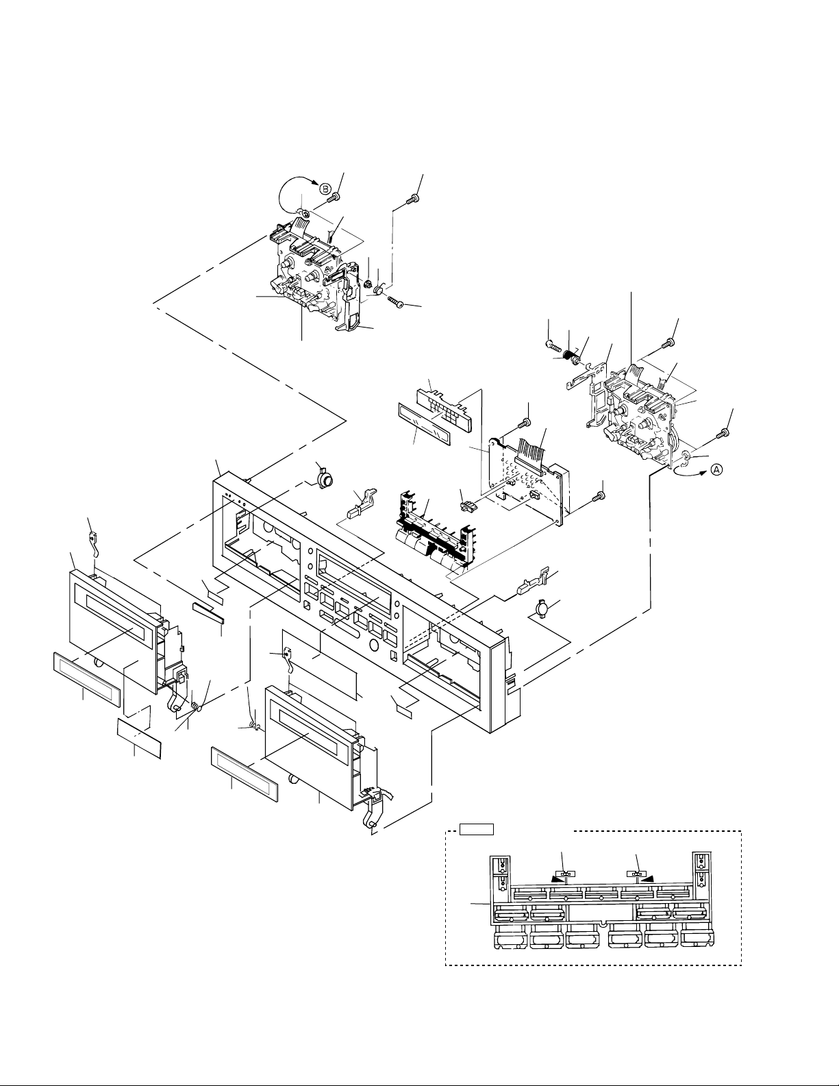
2.3 FRONT PANEL SECTION
23
11
27
32
30
3
5
Refer to " 2.4 MECHANISM SECTION "
25
12
18
13
10
15
21
32
31
14
20
28
Refer to " 2.4 MECHANISM SECTION "
31
9
13
16
32
2
1
32
19
12
32
4
6
32
30
22
29
17
8
22
11
27
26
7
24
Cutting position
Note
28
Cut
20
28
Cut
6
(1) FRONT PANEL SECTION PARTS LIST
Mark No. Description Part No.
1 SUB UNIT See Contrast table (2)
2 18P F.F.C/60V RDD1355
3 Connector Assy 3P RKP1678
4 Connector Assy 5P RKP1677
5 Mechanism Unit 1 (P) RYM1261
6 Mechanism Unit 2 (R/P) RYM1262
7 Door Spring L RBH1304
8 Door Spring R RBH1305
9 Eject Spring L RBH1379
10 Eject Spring R RBH1380
11 Half Pressure Spring RBK1004
12 Damper Assy REC1267
13 Eject Collar RLA1283
14 LED Holder RNK2194
15 Eject Lever R RNK2202
16 Eject Lever L RNK2203
17 Name Plate PAM1776
18 Eject Konb L RAC1881
19 Eject Konb R RAC1882
20 Control Button RAC2220
CT-W208R
21 Meter Panel RAH2702
22 Door Lens RAH2782
23 Door Pocket L RAH2900
24 Door Pocket R RAH2901
25 Front Panel See Contrast table (2)
26 Meter Lens RAH2903
27 Remain Display Paper REE-113
28 Slide Knob REA1293
NSP 30 Earth Lead Wire DE015VF0
29 Getter See Contrast table (2)
31 Screw BSZ26P120FMC
32 Screw BBZ30P080FZK
(2) CONTRAST TABLE
CT-W208R/KUXJ, KCXJ, HYXJ and HVXJ are constructed the same except for the following :
Mark Remarks
No.
1 SUB UNIT RWZ4353 RWZ4353 RWZ4349 RWZ4394
25 Front Panel RAH2902 RAH2902 RAH2899 RAH2899
29 Getter RAX1082 RAX1082 RAX1081 RAX1081
Symbol and Description
KUXJ type KCXJ type HYXJ type HVXJ type
Part No.
7
CT-W208R
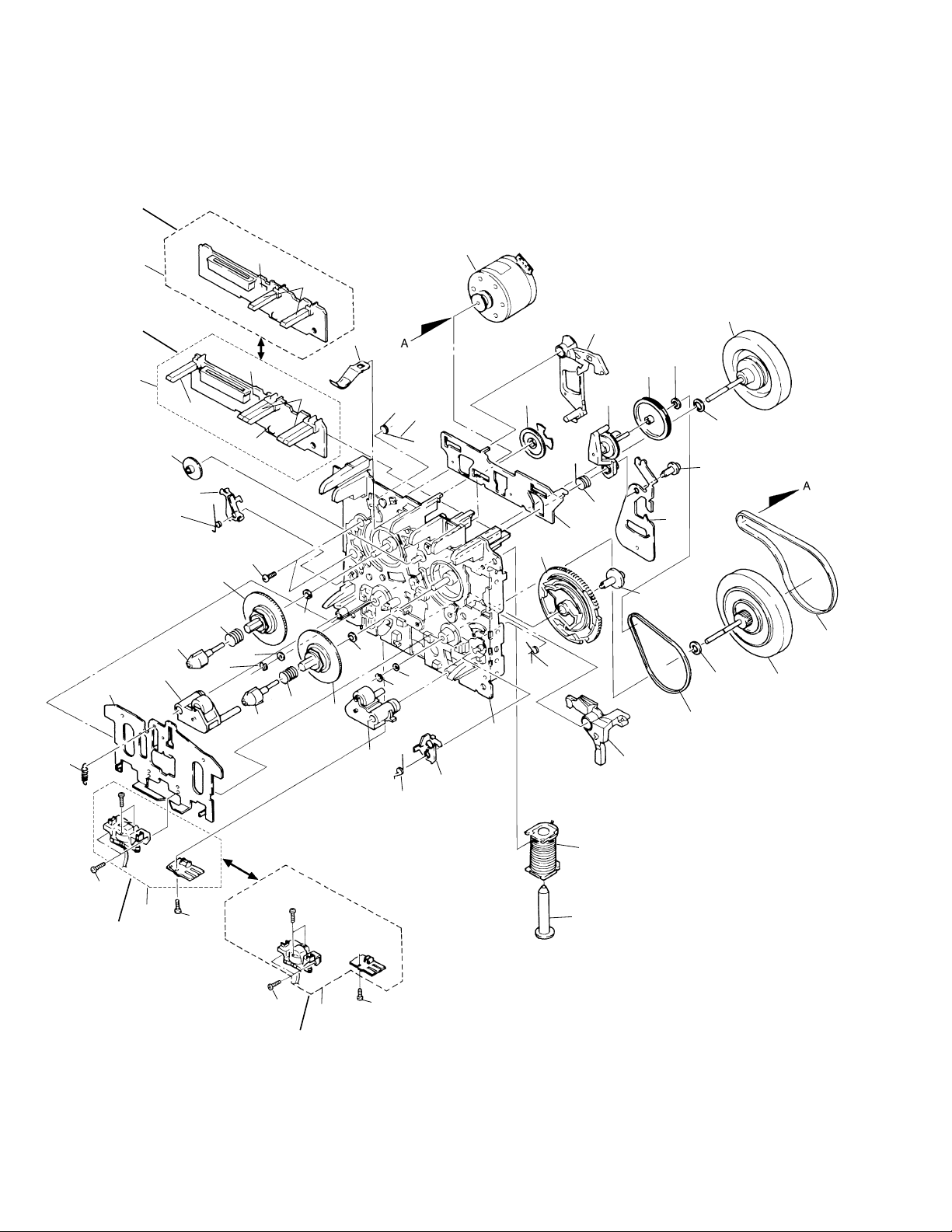
2.4 MECHANISM SECTION
For Mechanism Unit 1
51
For Mechanism Unit 2
2
37
36
17
28
39
26
33
3
4
47
3
26
22
20
4
11
20
50
41
27
16
8
4
5
48
27
21
50
41
6
13
19
49
15
49
12
18
14
32
30
44
23
31
25
40
46
29
45
42
10
9
35
38
For Mechanism Unit 2
8
34
35
52
For Mechanism Unit 1
7
1
34

MECHANISM UNIT PARTS LIST
CT-W208R
Mark No. Description Part No.
1 Plunge RLA1288
2 PCB CONTROL BLOCK RXA1733
(For Mechanism Unit 2 )
3 Push Switch RSG1018
4 SPLF RSN1023
5 PHOTO–TRANSISTOR SPI33534FG
6 MTR Main Block RXM1075
7 Solenoid Block RXP1021
8 Spring Interlock R RBH1386
9 Arm Interlock R RNE1781
10 Chassis Base Block RXA1626
11 Spring Brake RBH1387
12 Main Belt REB1157
13 F/R Belt REB1254
14 Lever Brake RNK2071
15 F/W ASSY RXA1295
16 Pinch Roller Block R RXA1628
17 Pinch Roller Block L RXA1629
18 F/W ASSY(Clutch) RXA1631
19 Screw RBA1120
20 Washer W41D065D025
21 Spring Reel(L) RBH1388
22 Spring Reel(R) RBH1389
23 CAM Spring RBH1393
24 • • • • •
25 Lever F/R RNE1782
Mark No. Description Part No.
41 Stop Ring YE15FUC
42 Spring ARM Play RBH1392
43 • • • • •
44 Plate Slide RNE1785
45 CAM Gear RNK2078
46 ARM Play RNK2079
47 Spring Cassette RNE1786
48 Screw BMZ26P040FZK
49 Washer WA26D045D025
50 Washer WA26D047D050
51 PCB Control Block RXA1623
(For Mechanism Unit 1)
52 Plate HD Block RXA1682
(For Mechanism Unit 1)
26 Reel Feather RNK2072
27 Reel Base RNK2073
28 PLAY Gear(A) RNK2074
29 FF Gear(A) RNK2075
30 F/R Pulley RNK2076
31 Clutch Block ASSY RXA1632
32 Washer WA17D040D025
33 ARM Interlock L RNE1780
34 Screw PCZ20P040FMC
35 Screw PMZ20P060FMC
36 Spring HB RBH1390
37 Head Base RNE1783
38 PLATE HD BLOCK RXA1683
(For Mechanism Unit 2 )
39 Spring Interlock L RBH1385
40 Screw RBA1121
9
1
23
CT-W208R
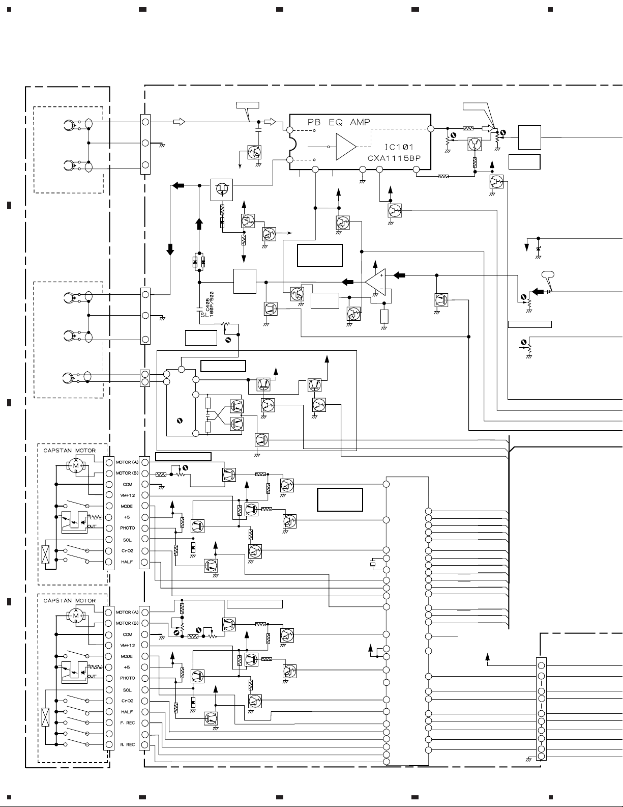
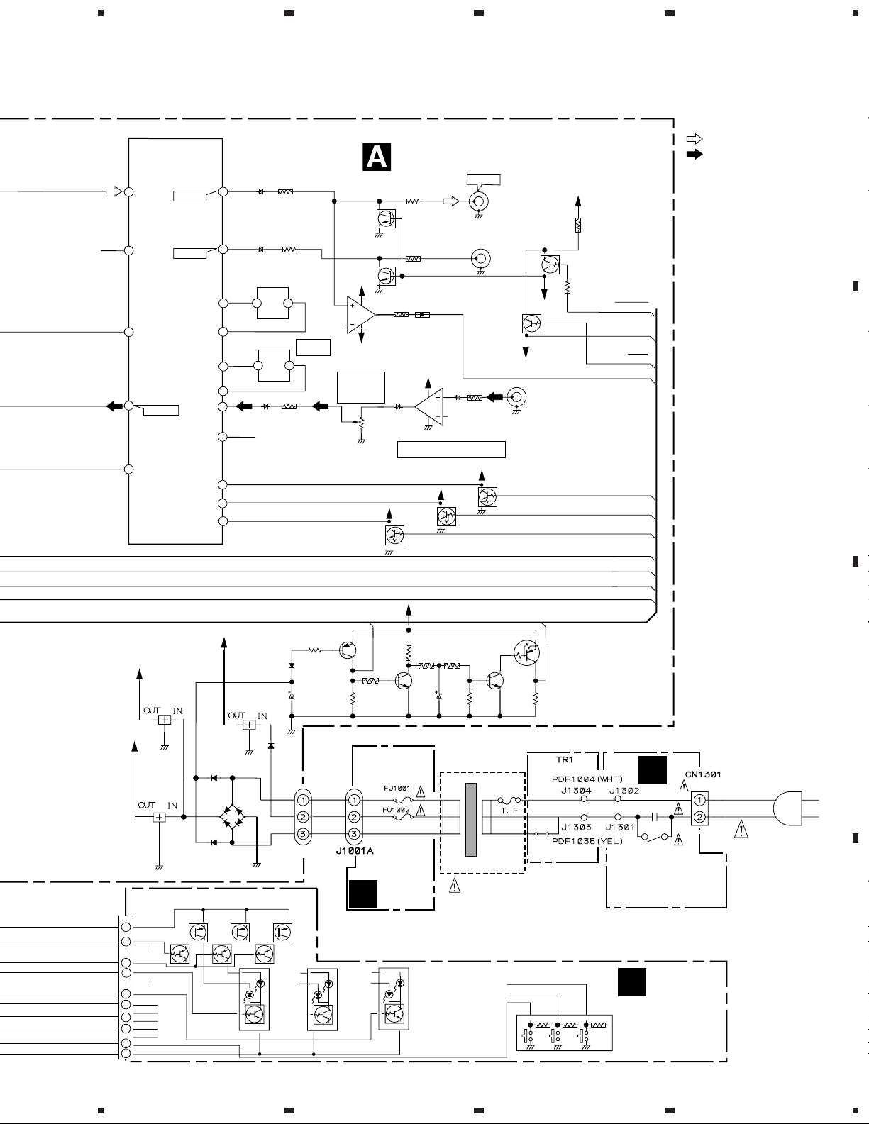
3. BLOCK DIAGRAM AND SCHEMATIC DIAGRAM
3.1 BLOCK DIAGRAM
Q101
DTC124ES
Q161
2SK373
S
S
D
D
G
G
VR401
PCP1032
100K-B
Q401
2SC1815
Q402
2SC1815
VC5V
Q806
DTC124ES
Q807
2SC3311A
GNDC
TAPE SPEED ADJ
2SA1309A
VC5V
GNDC
-73.5dBv
X1
VA12
DTA114ES
VE5V
BIAS
TRAP
VC12
GNDC
Q851
VC12
GNDC
C101
330P
GNDA
Q165
GNDA
GNDA
GNDA
GNDA
Q803
2SB1425
Q803
2SB1425
Q856
DTC124ES
Q166
DTC124ES
Q311
2SD2114S
VA12
Q404
2SB1238X
Q406
DTC114TS
BIAS
Q403
2SD1302
GNDC
GNDC
2
1
2PB
Q301
DTC124EK
Q802
DTC124ES
DTC124ES
GNDC
Q852
DTC124ES
DTC124ES
GNDC
REC EQ
Q804
Q854
AMP
REC EQ
SWITCHE
DTC124EK
2SB1238X
GNDA
Q407
DTC114TS
MECHA
VA12
GNDA
Q307
VA12
Q405
CONT
GNDA
Q313
DTC124EK
GNDA
X501
RSS1045
6.3MHz
7
CPM1
SOL1
MOD1
HAF1
CRO1
SEN1
VC5V
CPM2
SOL2
SEN2
MOD2
CRO2
HAF2
FRC2
MET2
RRC2
X1
8
4
GNDA
X 1
X 1
GNDA
VA12
GNDA
52
54
53
30
31
20
22
21
52
56
16
55
10
14
15
16
17
18
19
VA12
DTC114TS
IC301(1/2)
BA15218
5
6
PD5351A
µ-COM
9
1
2
Q105
IC501
A
MECHA UNIT 1
(RYM1261)
B
ERACE
HEAD
MECHA UNIT 2
(RYM1262)
C
D
PB
HEAD
1 –MECHA
UNIT(1/2)
REC/PB
HEAD
2 –MECHA
UNIT(1/2)
1 –MECHA
2 –MECHA
1
2
3
4
5
6
7
8
9
10
2
3
4
5
6
7
8
9
10
11
12
13
CN101
CN102
CN401
J801
VR2701
RCP1024
1K-B
MET
J851
Lch
1
2
GNDA
Rch
3
Lch
3
2
GNDA
Rch
1
6
1
4
2
TAPE SPEED ADJ
1
2
3
PCP1024
GNDC
4
VC5V
5
6
7
8
9
10
VR851
PCP1025
2.2K-B
11
2
3
GNDC
4
VC5V
5
6
7
8
9
10
11
12
13
5
f : 105kHz
L401
RTD1077
VR801
1K-B
REC BIAS
ADJ
2
1
3
2SA1309A
2SB1238X
GNDC
VR852
PCP1024
1K-B
2SB1238X
GNDC
Q857
2SC3311A
BIAS OSC
Q801
Q805
Q855
4
1 MECHANISM 2 MECHANISM
PCP1031
4
9106 15
PB NR
GNDA
62
51
50
61
60
12
59
58
52
64
63
13
28
27
4
METR
5
34
GLD0
42
39
38
33
11
OKY1
44
8
6
VR101
47K-B
GNDA
Q309
2SC3311A
POWER OFF
-31.2dBv
Q103
DTC115TS
DTC114TS
BIAS
TP0
TP1
DEC
2 PB
DOL 0
PBNR
MGAN
X 1
LMUT
RMUT
DOL B
REST
METL
Q106
VC5V
GNDA
GNDA
BIAS
TP0
TP1
VR103
PCP1031
47K-B
VA12
CN1503
BIAS
TRAP
PB LEVEL
ADJ
2 PB
D2201
MTZ6.2A
Vref
GNDA
VR301
PCP1030
22K-B
GNDA
REC LEVEL ADJ.
GNDA
2 PB
PB NR
X 1
RECMUTE
VC5V
18
GLD0
17
GLD3GLD3
14
SLD0SLD0
13
SLD5SLD5
8
SW0SW0
7
OKY1
5
KEY0KEY0
4
KEY2KEY2
2
GNDC
1
TP1
+
10
1234
5
678
CT-W208R
Note : When ordering service parts, be sure to refer to "EXPLODED VIEWS and P AR TS LIST" or "PCB PARTS LIST".
DOLBY-B/C NR
2
PB IN RcH
21
4
9
-7.2dBv
14
2 PB
PB NR
X 1
RECMUTE
IC201
CXA1560S
-1.2dBv
-1.2dBv
6
17
4
5
19
18
3
20
10
12
13
LIN IN RcH
+
+
F201
RTF1208
MPX
F202
RTF1208
MPX
+
:PLAYBACK SIGNAL ROUTE
MAIN UNIT
-6.0dBv
Q702
2SD2144S
GNDA
VC5V
MPX
5
6
VE5V
36
36
INPUT
VR
GNDA
Q201
DTC124ES
GNDA
8
7
4
VR701(2/2)
RCV1089
5KA
VA12
GNDA
2SD2144S
IC701(2/2)
BA15218
Q701
VA12
8
7
+
4
GNDA
INPUT BUFFER
VA12
Q202
DTC124ES
GNDA
VC5V
5
6
GNDA
+
GNDA
VA12
GNDA
LINEOUT
Lch
LINEOUT
Rch
Q502
DTA114TS
GNDA
DTC124ES
VE5V
Q203
LINEIN
Lch
VE5V
VA12
Q751
DTA114TS
LINEMUTE
REMU
REMU
METL
DOL 0
(ON/OFF)
DOL B
(B/C)
DEC
2 PB
PB NR
X 1
RECMUTE
:RECRDING SIGNAL ROUTE
A
B
VC12
NJM7812FA
VA12
NJM7812FA
CN1501
VC5V
18
GLD0
17
GLD3
14
SLD0
13
SLD5
8
SW0
7
OKY0
OKY1
5
KEY0
4
KEY1
KEY2
2
GNDC
1
GNDC
GNDA
IC1002
IC1001
Q1514
2SA1309A
S2VB20
D1003
Q1513,Q1512
Q1501
DTC114TS
VC5V
NJM78M05FA
IC1003
GNDC
GNDA
2SA1309A
GNDC
J1001
Q1511
2SA1309A
Q1507
DTA114TS
Q1502
– Q1505
DTC114TS
Q1001
2SA1309A
POFF
2SC3311A
FU1001, FU1002:
TRN 2 UNIT
C
Q1506
DTC114TS
Q1002
Q1003
2SC3311A
REST
Q1004
DTA114TS
POWER TRANSFORMER
KEY0
KEY1
KEY2
KEY2
S1602 ~ S1624
D
POWER SW UNIT
SUBB
B
UNIT
C
AC POWER CORD
NEUTRAL
LIVE
D
11
5
6
7
8
 Loading...