

Pioneer CTL-5 Service manual
ASES
8
¶
DOLBY B NR
Ÿ
¡1
2
0
3
7
STEREO CASSETTE DECK
CT-L5
THIS MANUAL IS APPLICABLE TO THE FOLLOWING MODEL(S) AND TYPE(S).
ORDER NO.
RRV1996
Type
ZVYXK ‡ DC power supplied from other system component
Model
Power Requirement
CT-L5
÷ These products are component of systems.
For the system composition, accessories, instruction manuals etc., refer to the service manuals
RRV1997 for XC-L5/MYXK and RRV1986 for MJ-L5/MYXK (SP-L5/MYXK).
÷ This product does not operate normally by itself. Please connect it to the STEREO CD RECEIVER
XC-L5 , for adjustment and operation inspection. If operation confirmation for the unit by itself can
not be avoided, please follow the instructions on page 22.
CONTENTS
1. SAFETY INFORMATION....................................2
2. EXPLODED VIEWS AND PARTS LIST .............3
3. SCHEMATIC DIAGRAM................................... 11
4. PCB CONNECTION DIAGRAM .......................16
5. PCB PARTS LIST.............................................20
6. ADJUSTMENT.................................................. 22
PIONEER ELECTRONIC CORPORATION 4-1, Meguro 1-Chome, Meguro-ku, Tokyo 153-8654, Japan
PIONEER ELECTRONICS SERVICE, INC. P.O. Box 1760, Long Beach, CA 90801-1760, U.S.A.
PIONEER ELECTRONIC (EUROPE) N.V. Haven 1087, Keetberglaan 1, 9120 Melsele, Belgium
PIONEER ELECTRONICS ASIACENTRE PTE. LTD. 501 Orchard Road, #10-00 Wheelock Place, Singapore 238880
PIONEER ELECTRONIC CORPORATION 1998
7. GENERAL INFORMATION .............................. 26
7.1 IC................................................................ 26
8. PANEL FACILITIES AND SPECIFICATIONS
...................................................................27
T–ZZR AUG. 1998 Printed in Japan
CT-L5
1. SAFETY INFORMATION
This service manual is intended for qualified service technicians; it is not meant for the casual
do-it-yourselfer. Qualified technicians have the necessary test equipment and tools, and have been
trained to properly and safely repair complex products such as those covered by this manual.
Improperly performed repairs can adversely affect the safety and reliability of the product and may
void the warranty . If you are not qualified to perform the repair of this product properly and safely, you
should not risk trying to do so and refer the repair to a qualified service technician.
WARNING
This product contains lead in solder and certain electrical parts contain chemicals which are known to the state of California to
cause cancer, birth defects or other reproductive harm.
Health & Safety Code Section 25249.6 – Proposition 65
NOTICE
(FOR CANADIAN MODEL ONLY)
Fuse symbols (fast operating fuse) and/or (slow operating fuse) on PCB indicate that replacement
parts must be of identical designation.
REMARQUE
(POUR MODÈLE CANADIEN SEULEMENT)
Les symboles de fusible (fusible de type rapide) et/ou (fusible de type lent) sur CCI indiquent que
les pièces de remplacement doivent avoir la même désignation.
(FOR USA MODEL ONLY)
1. SAFETY PRECAUTIONS
The following check should be performed for the
continued protection of the customer and service
technician.
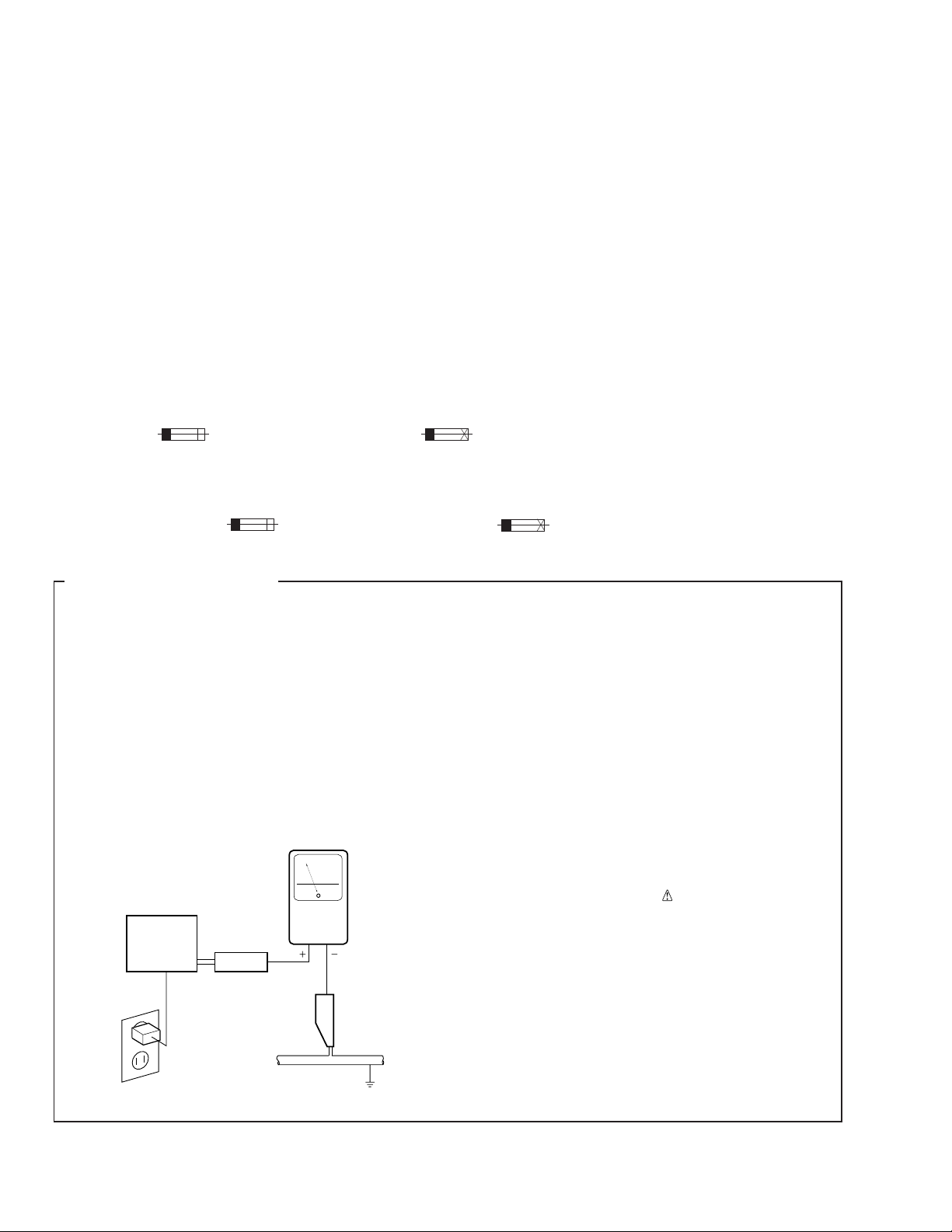
LEAKAGE CURRENT CHECK
Measure leakage current to a known earth ground
(water pipe, conduit, etc.) by connecting a leakage
current tester such as Simpson Model 229-2 or
equivalent between the earth ground and all exposed
metal parts of the appliance (input/output terminals,
screwheads, metal overlays, control shaft, etc.). Plug
the AC line cord of the appliance directly into a 120V
AC 60 Hz outlet and turn the AC power switch on. Any
current measured must not exceed 0.5 mA.
Reading should
not be above
0.5 mA
Earth
ground
Device
under
test
Also test with
plug reversed
(Using AC adapter
plug as required)
Test all
exposed metal
surfaces
AC Leakage Test
Leakage
current
tester
ANY MEASUREMENTS NOT WITHIN THE
LIMITS OUTLINED ABOVE ARE INDICATIVE
OF A POTENTIAL SHOCK HAZARD AND
MUST BE CORRECTED BEFORE RETURNING THE APPLIANCE TO THE CUSTOMER.
2. PRODUCT SAFETY NOTICE
Many electrical and mechanical parts in the appliance
have special safety related characteristics. These are
often not evident from visual inspection nor the
protection afforded by them necessarily can be obtained
by using replacement components rated for voltage,
wattage, etc. Replacement parts which have these
special safety characteristics are identified in this
Service Manual.
Electrical components having such features are
identified by marking with a
on the parts list in this Service Manual.
The use of a substitute replacement component which
does not have the same safety characteristics as the
PIONEER recommended replacement one, shown in the
parts list in this Service Manual, may create shock, fire,
or other hazards.
Product Safety is continuously under review and new
instructions are issued from time to time. For the latest
information, always consult the current PIONEER
Service Manual. A subscription to, or additional copies
of, PIONEER Service Manual may be obtained at a
nominal charge from PIONEER.
on the schematics and
2
2. EXPLODED VIEWS AND PARTS LIST
NOTES : ÷ Parts marked by “ NSP ” are generally unavailable because they are not in our Master Spare Parts List.
÷ The
÷ Screw adjacent to ∞ mark on the product are used for disassembly.
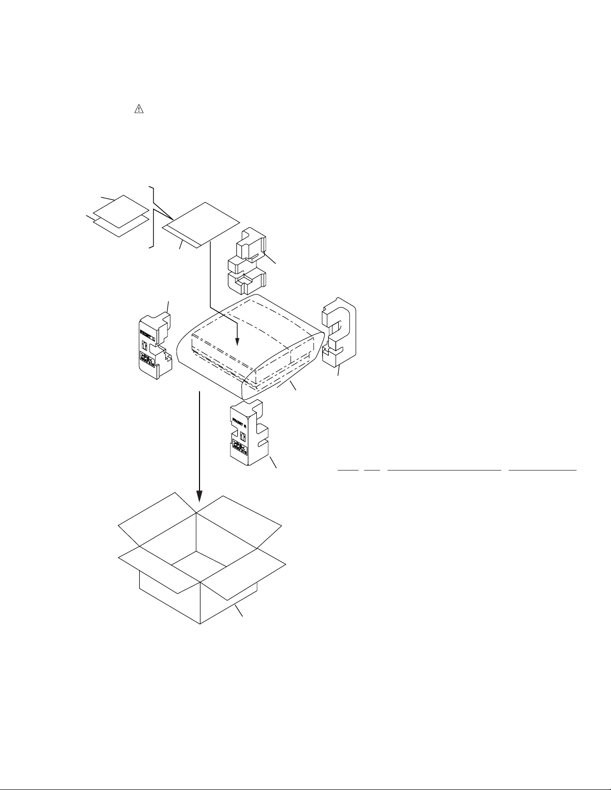
2.1 PACKING
5
4
mark found on some component parts indicates the importance of the safety factor of the part.
Therefore, when replacing, be sure to use parts of identical designation.
CT-L5
6
1 (1/2)
2 (1/2)
1 (2/2)
2 (2/2)
7
÷
PACKING PARTS LIST
Mark No. Description Parts No.
1 Pad F AHA7219
2 Pad R AHA7220
3 Packing Case AHD7629
4 Operating Instructions ARE7177
(English/ French/ German/ Italian/
NSP 5 Warranty Card ARY7022
Dutch/ Swedish/ Spanish/ Portuguese)
6 Polyethylene Bag Z21-038
(0.03 × 230 × 340)
7 Packing Sheet Z23-007
(750 × 600 × 0.5)
3
3
CT-L5
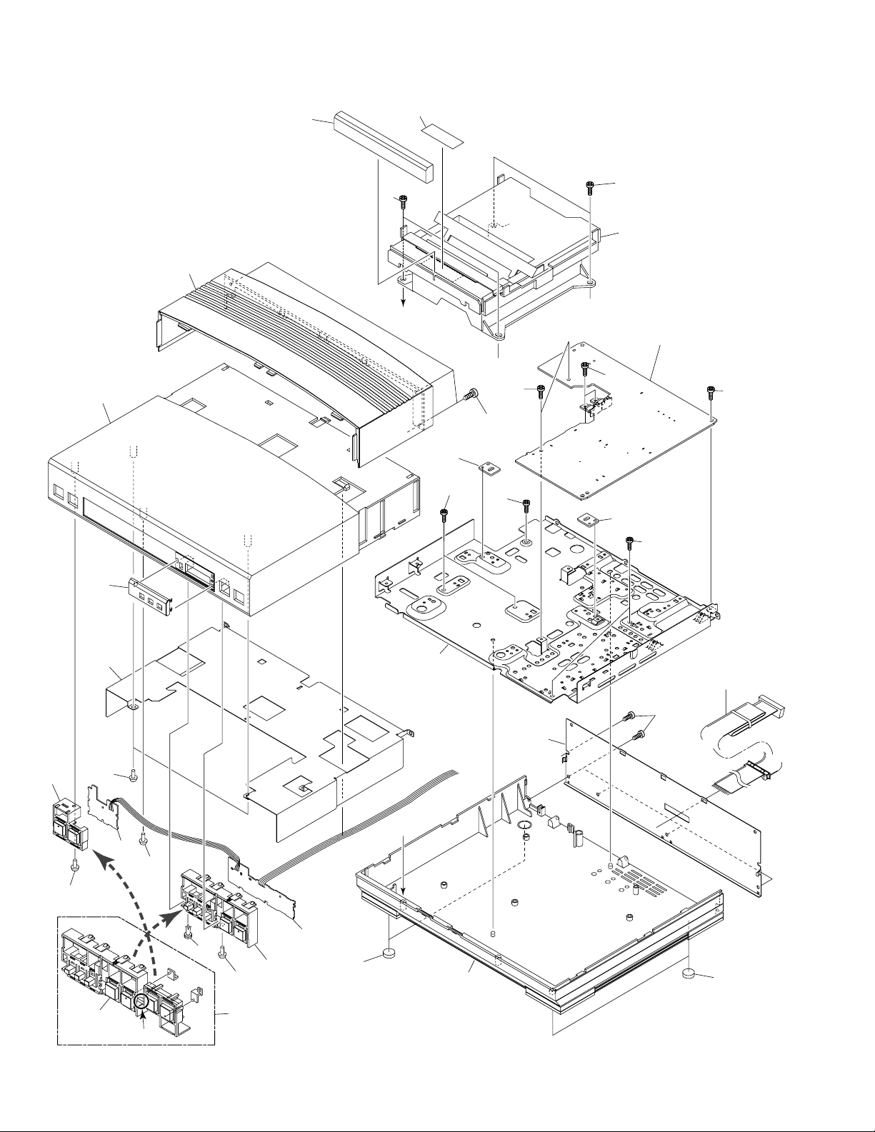
2.2 EXTERIOR
16
17
13
23
19
23
5
Refer to " 2.3 MECHANISM
UNIT (1/2)".
A
1 (1/3)
20
1(2/3)
21
20
22
21
1(3/3)
20
18
(2/2)
22
14
22
21
9
8
4
22
7
A
2
11
3
10
22
18 (1/2)
6
15
6
25
Cut
18
4

÷ EXTERIOR SECTION PARTS LIST
Mark No. Description Parts No.
1 MAIN UNIT AWU7110
2 KEY L UNIT AWU7112
3 KEY R UNIT AWU7111
4 Connection Cable ADE7026
5 Mechanism Unit AXA7070
6 Leg AEB7090
7 Rear Panel ANC7674
NSP 8 Bottom Plate ANF7011
NSP 9 Top Plate ANK7042
10 Rivet VEC1178
11 Screw IPZ30P080FMC
12 ...............
13 Tray Panel CT AAN7185
14 Sub Panel AAP7053
15 Bottom Base AMA7006
16 Top Panel AMB7514
17 Bonnet AMA7007
18 Button X ASSY AWL7033
NSP 19 Tray Seal RRW1162
20 Screw BBZ30P060FMC
CT-L5
21 Screw BPZ30P060FZK
22 Screw VPZ30P080FZK
23 Screw PPZ30P150FMC
24 ...............
NSP 25 Button AAD7473
5
CT-L5
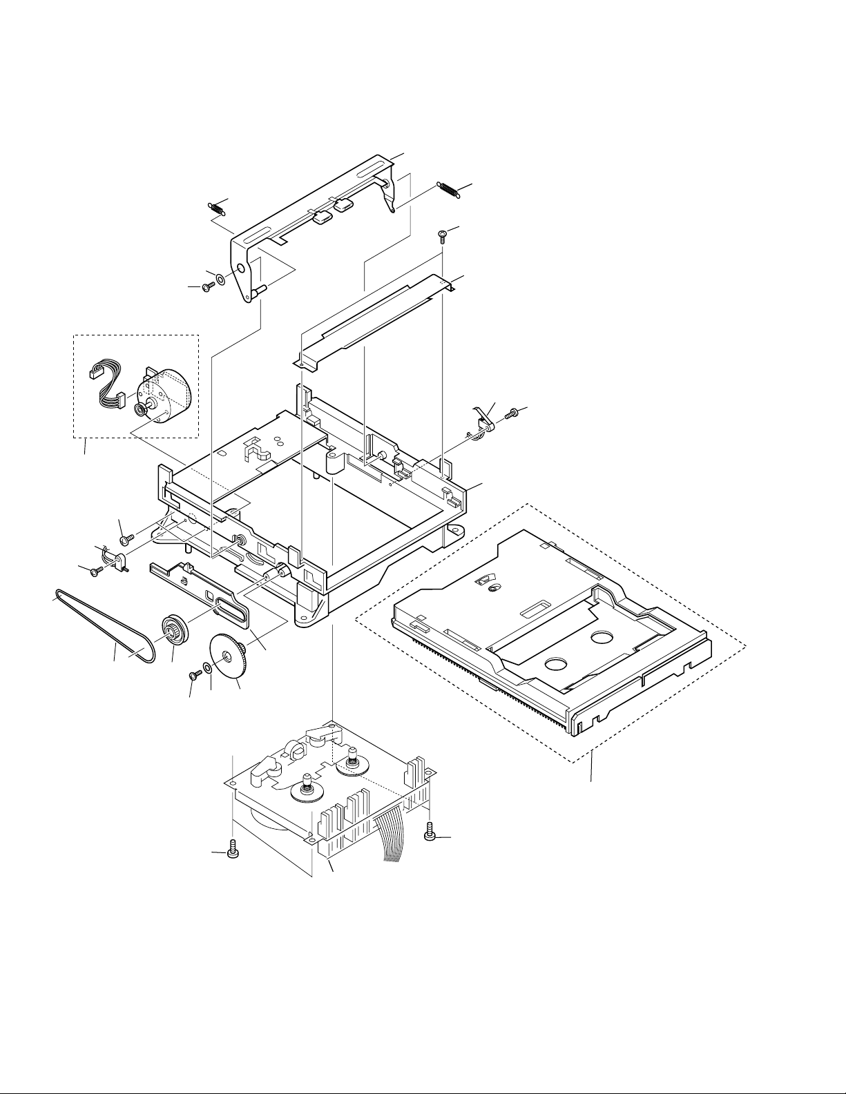
2.3 MECHANISM UNIT (1/2)
17
6
5
16
16
14
13
12
4
16
1
11
9
3
18
16
8
19
16
6
10
7
2
2
Refer to "2.4 MECHANISM UNIT (2/2)".

÷ MECHANISM UNIT (1/2) PARTS LIST
Mark No. Description Parts No.
1 Screw FG114-14
2 Screw UG12H-15
3 Front BLK FC64K-11
4 Washer MJ112-22
5 SP Return FK34N-11
6 Plate Hold BLK F573-258
7 Holder CST BLK F527-078
8 LDG Base FD56R-12
9 Pulley FD56T-11
10 LDG Gear FD56U-11
11 Slider FD57E-11
12 LDG Belt FF19L-12
13 Switch UE15S-14
14 MTR Reel BLK F564-313
15 ...............
16 Screw UG12H-28
17 SP Clamper FK34M-11
18 Switch UE18P-21
CT-L5
7
CT-L5
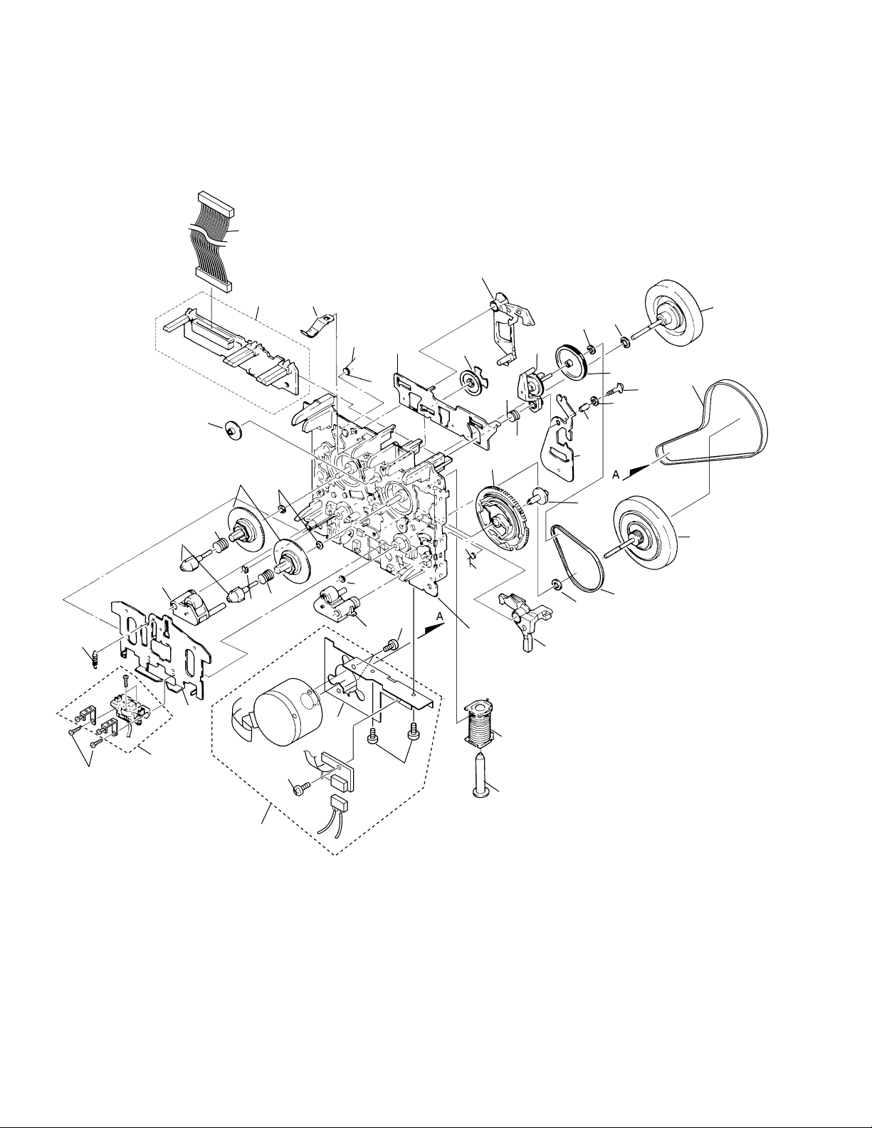
2.4 MECHANISM UNIT (2/2)
39
33
40
19
15
12
10
4
2
32
8
30
23
5
14
31
32
7
3
18
34
11
6
16
35
21
24
41
42
43
37
36
26
30
13
20
27
22
17
28
1
8
1
29
9
25
3
38

÷ MECHANISM UNIT (2/2) PARTS LIST
Mark No. Description Parts No.
1 Screw KG194-36
2 Reel Feather FD57D-13
3 Screw UG11S-14
4 SP Reel(L) FK32U-12
5 SP Brake FK33B-13
6 SP Arm Play FK33P-11
7 SP Reel(R) FK32V-12
8 Spring Cassette FC65M-11
9 BKT MTR FC64M-12
10 Reel Base FD52W-12
11 Cam Gear FD52Y-23
12 Play Gear (A) FD53K-12
13 Arm Play FD53D-19
14 Plate Slide FC61L-19
15 PCB Control BLK F567-617
16 Chassis base BLK F612-231
17 Head Base FC61K-32
18 Roller Pinch BLK R F514-129
19 Roller Pinch BLK L F514-130
20 Assy F/W FR24S-11
CT-L5
21 Clutch Assy BLK F522-037
22 Clutch Assy BLK F522-042
23 Washer FJ111-13
24 F/R Pulley FD53F-15
25 Solenoid BLK F765-279
26 F/R Belt FF18W-12
27 Belt Main FF19H-11
28 Plate HD BLK F513-824
29 MTR MAIN BLK F525-321
30 Washer FJ111-30
31 Washer FJ111-35
32 Washer UJ16F-11
33 Lever Brake FD53P-17
34 FF Gear(A) FD53L-12
35 Cam SP FK32S-14
36 Screw UJ14A-12
37 Lever F/R FC62G-14
38 Plunger FL41S-21
39 Mecha-Cable WH65N-11
40 Spring HB FK32T- 31
41 Screw UG15V-13
42 Washer MJ112- 22
43 Washer UJ15V- 13
9
 Loading...