

PIONEER CDX-MG6047, CDX-MG6147 Service Manual
PIONEER CORPORATION 4-1, Meguro 1-chome, Meguro-ku, Tokyo 153-8654, Japan
PIONEER ELECTRONICS (USA) INC. P.O. Box 1760, Long Beach, CA 90801-1760, U.S.A.
PIONEER EUROPE NV Haven 1087, Keetberglaan 1, 9120 Melsele, Belgium
PIONEER ELECTRONICS ASIACENTRE PTE. LTD. 253 Alexandra Road, #04-01, Singapore 159936
PIONEER CORPORATION 2004
HONDA
ORDER NO.
CRT3322
CDX-MG6047ZH/UC
6 DISC IN-DASH CD CHANGER
CDX-MG6047
CDX-MG6147
VEHICLE DESTINATION
PILOT U.S.A. August 2004 39110-S9V-A110-M1 ••••• CDX-MG6047ZH/UC
PILOT U.S.A. August 2004 39110-S9V-A210-M1 ••••• CDX-MG6147ZH/UC
This service manual should be used together with the following manual(s):
Model No. Order No. Mech.Module Remarks
CX-890 CRT2376 G1 CD Mech. Module : Circuit Description, Mech. Description, Disassembly
PRODUCED
AFTER
ZH
OEM PARTS No. ID No. PIONEER MODEL No.
/UC
ZH
/UC
To operate this product, a 14-pin H-BUS head unit is required.
When performing adjustments, connect the 8-pin/14-pin conversion jig (GGD1163) and the 14-pin/13-pin
conversion jig (GGD1412) to a Pioneer 8-pin H-BUS head unit. You can use it in place of a 14-pin H-BUS
head unit.
For details, refer to "Important symbols for good services".
K-ZZA. AUG. 2004 printed in Japan
1234
SAFETY INFORMATION
CAUTION
A
This service manual is intended for qualified service technicians; it is not meant for the casual do-it-yourselfer.
Qualified technicians have the necessary test equipment and tools, and have been trained to properly and safely
complex products such as those covered by this manual.
repair
Improperly performed repairs can adversely affect the safety and reliability of the product and may void the
warranty.
trying to do so
W
ARNING
This product contains lead in solder and certain electrical parts contain chemicals which are known to the
state
Health & Safety Code Section 25249.6 - Proposition 65
B
- Service Precaution
1. You should conform to the regulations governing the
product (safety, radio and noise, and other regulations),
and should keep the safety during servicing by following
the safety instructions described in this manual.
2. Never attempt to turn on this unit when the CD drive
C
mechanism is upside down. Doing so could cause
damage or malfunction to the drive mechanism.
3. For pickup unit(CXX1311) handling, please refer
to"Disassembly"(see page 58).
During replacement, handling precautions shall be
taken to prevent an electrostatic discharge(protection
by a short pin).
4. During disassembly, be sure to turn the power off
since an internal IC might be destroyed when a con-
D
nector is plugged or unplugged.
5. Please checking the grating after changing the ser vice pickup unit(see page 56).
If you are not qualified to perform the repair of this product properly and safely, you should not risk
and refer the repair to a qualified service technician.
of California to cause cancer, birth defects or other reproductive harm.
E
F
2
1234
CDX-MG6047ZH/UC
5678
[Important Check Points for Good Servicing]
In this manual, procedures that must be performed during repairs are marked with the below symbol.
Please be sure to confirm and follow these procedures.
1. Product safety
Please conform to product regulations (such as safety and radiation regulations), and maintain a safe servicing environment by
following the safety instructions described in this manual.
1 Use specified parts for repair.
Use genuine parts. Be sure to use important parts for safety.
2 Do not perform modifications without proper instructions.
Please follow the specified safety methods when modification(addition/change of parts) is required due to interferences such as
radio/TV interference and foreign noise.
3 Make sure the soldering of repaired locations is properly performed.
When you solder while repairing, please be sure that there are no cold solder and other debris.
Soldering should be finished with the proper quantity. (Refer to the example)
4 Make sure the screws are tightly fastened.
Please be sure that all screws are fastened, and that there are no loose screws.
5 Make sure each connectors are correctly inserted.
Please be sure that all connectors are inserted, and that there are no imperfect insertion.
6 Make sure the wiring cables are set to their original state.
Please replace the wiring and cables to the original state after repairs.
In addition, be sure that there are no pinched wires, etc.
7 Make sure screws and soldering scraps do not remain inside the product.
Please check that neither solder debris nor screws remain inside the product.
8 There should be no semi-broken wires, scratches, melting, etc. on the coating of the power cord.
Damaged power cords may lead to fire accidents, so please be sure that there are no damages.
If you find a damaged power cord, please exchange it with a suitable one.
9 There should be no spark traces or similar marks on the power plug.
When spark traces or similar marks are found on the power supply plug, please check the connection and advise on secure
connections and suitable usage. Please exchange the power cord if necessary.
0 Safe environment should be secured during servicing.
When you perform repairs, please pay attention to static electricity, furniture, household articles, etc. in order to prevent injuries.
Please pay attention to your surroundings and repair safely.
A
B
C
D
2. Adjustments
To keep the original performance of the products, optimum adjustments and confirmation of characteristics within specification.
Adjustments should be performed in accordance with the procedures/instructions described in this manual.
3. Lubricants, Glues, and Replacement parts
Use grease and adhesives that are equal to the specified substance.
Make sure the proper amount is applied.
4. Cleaning
For parts that require cleaning, such as optical pickups, tape deck heads, lenses and mirrors used in projection monitors, proper
cleaning should be performed to restore their performances.
5. Shipping mode and Shipping screws
To protect products from damages or failures during transit, the shipping mode should be set or the shipping screws should be
installed before shipment. Please be sure to follow this method especially if it is specified in this manual.
56
CDX-MG6047ZH/UC
E
F
7
8
3

1234
CONTENTS
SAFETY INFORMATION.....................................................................................................................................2
1. SPECIFICATIONS ............................................................................................................................................ 5
2. EXPLODED VIEWS AND PARTS LIST............................................................................................................ 6
A
B
C
D
2.1 PACKING ................................................................................................................................................... 6
2.2 EXTERIOR................................................................................................................................................. 8
2.3 CD MECHANISM.....................................................................................................................................10
3. BLOCK DIAGRAM AND SCHEMATIC DIAGRAM..........................................................................................14
3.1 BLOCK DIAGRAM...................................................................................................................................14
3.2 OVERALL CONNECTION DIAGRAM(GUIDE PAGE).............................................................................. 16
3.3 CD CORE UNIT(SERVO UNIT)...............................................................................................................22
3.4 CD CORE UNIT(STS UNIT) .................................................................................................................... 24
3.5 PCB UNIT(A, B, C, D, E), LOAD MOTOR PCB........................................................................................ 29
4. PCB CONNECTION DIAGRAM ..................................................................................................................... 30
4.1 EXTENSION UNIT...................................................................................................................................30
4.2 KEYBOARD UNIT.................................................................................................................................... 32
4.3 CD CORE UNIT(SERVO UNIT)...............................................................................................................34
4.4 CD CORE UNIT(STS UNIT) .................................................................................................................... 36
4.5 MOTOR PCB(B)....................................................................................................................................... 38
4.6 MOTOR PCB(A)....................................................................................................................................... 40
4.7 PCB UNIT(D) AND PCB UNIT(B)............................................................................................................42
4.8 PCB UNIT(E)............................................................................................................................................43
4.9 PCB UNIT(C) ........................................................................................................................................... 44
4.10 LOAD MOTOR PCB AND PCB UNIT(A)................................................................................................ 45
5. ELECTRICAL PARTS LIST ............................................................................................................................ 46
6. ADJUSTMENT ...............................................................................................................................................51
6.1 TEST MODE ............................................................................................................................................ 51
6.2 CHECKING THE GRATING AFTER CHANGING THE PICKUP UNIT....................................................56
7. GENERAL INFORMATION.............................................................................................................................58
7.1 DIAGNOSIS.............................................................................................................................................58
7.1.1 DISASSEMBLY ..................................................................................................................................... 58
7.1.2 PCB LOCATIONS ................................................................................................................................. 62
7.1.3 CONNECTOR FUNCTION DESCRIPTION.......................................................................................... 63
7.2 IC ............................................................................................................................................................. 64
7.3 SYSTEM BLOCK DIAGRAM ................................................................................................................... 66
7.4 NOTES ON SERVICING..........................................................................................................................67
7.4.1 CLEANING............................................................................................................................................ 67
7.4.2 FACTORY SETTINGS...........................................................................................................................67
8. OPERATIONS ................................................................................................................................................68
E
F
4
1234
CDX-MG6047ZH/UC

5678
1. SPECIFICATIONS
General
Power source ...................... 13.2 V DC (10.8 – 16 V allowable)
Grounding system ............................................... Negative type
Backup current ...................................................... 2 mA or less
Maximum current consumption ................................ 1.5 A max.
Dimensions (chassis size) ...... 180 (W) × 50 (H) × 168 (D) mm
................................................[7-1/8 (W) × 2 (H) × 6-5/8 (D) in.]
Weight ................................................................ 1.6 kg (3.5 lbs)
CD player
A
System .......................................... Compact disc audio system
Usable discs ......................................................... Compact disc
Signal format .............................. Sampling frequency: 44.1 kHz
.........................................Number of quantization bits: 16;linear
Frequency characteristics ................................. 20 – 20,000 Hz
Signal-to-noise ratio ................... 92 dB (1kHz) (IHF-A network)
Dynamic range ..................................................... 92 dB (1kHz)
Number of channels ................................................... 2 (stereo)
B
C
D
E
F
56
CDX-MG6047ZH/UC
7
8
5
N
1234
2. EXPLODED VIEWS AND PARTS LIST
OTES : • Parts marked by " * " are generally unavailable because they are not in our Master Spare Parts List.
A
• Screw adjacent to mark on the product are used for disassembly.
• For the applying amount of lobricants or glue, follow the instructions in this manual.
(In the case of no amount instructions,apply as you think it appropriate.)
"
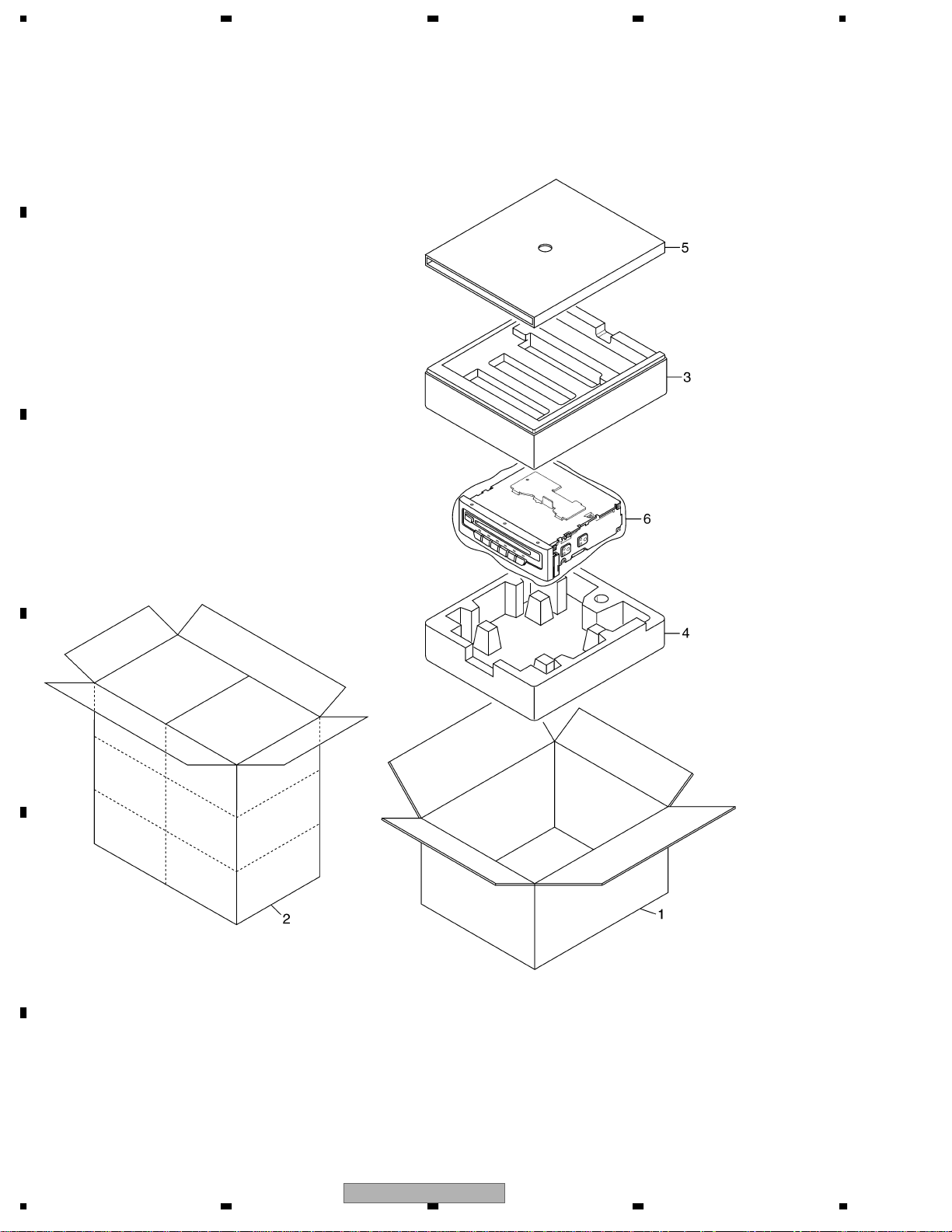
2.1 PACKING
B
C
D
E
F
6
1234
CDX-MG6047ZH/UC
5678
(1) PACKING SECTION PARTS LIST
Mark No. Description Part No.
1 Carton See Contrast table(2)
2 Contain Box See Contrast table(2)
3 Protector CHP2123
4 Protector CHP2124
Mark No. Description Part No.
5 Protector CHP2435
* 6 Polyethylene Bag E36-609
(2) CONTRAST TABLE
CDX-MG6047ZH/UC and CDX-MG6147ZH/UC are constructed the same except for the following:
Mark NO Description CDX-MG6047ZH/UC CDX-MG6147ZH/UC
1 Carton CHG5268 CHG5269
2 Contain Box CHL5268 CHL5269
A
B
C
D
E
56
CDX-MG6047ZH/UC
F
7
8
7
1234
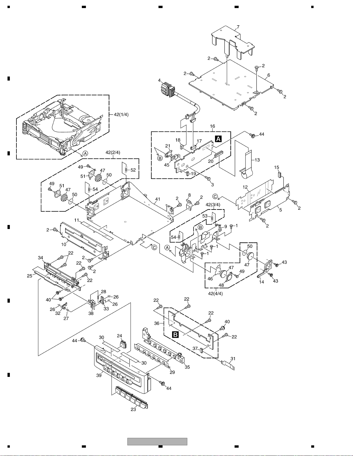
2.2 EXTERIOR
A
B
C
D
E
F
8
1234
CDX-MG6047ZH/UC
5678
(1) EXTERIOR SECTION PARTS LIST
Mark No. Description Part No.
1 Screw BMZ20P020FTC
2 Screw BMZ26P030FTC
3 Screw BMZ26P060FTC
4 Cord CDE7595
5 Side Frame CNB2397
6 Case CNB2988
7 Bracket CNC7878
8 Holder CNC8111
9 Bracket CNC8816
10 Front Frame CND2205
11 Insulator CNM5969
12 Insulator CNM6112
13 PCB CNP5516
14 Holder CNV5543
15 Spacer CNV8406
16 Control Unit CWM9600
17 Connector(CN102) CKS2200
18 Connector(CN103) CKS3597
19 Connector(CN701) CKS3785
20 Connector(CN101) CKS3989
21 Holder CNC8031
22 Screw BPZ20P060FTC
23 Button(1-6) See Contrast table(2)
24 Button(EJECT) See Contrast table(2)
25 Door CAT2587
26 Washer CBF1038
27 Spring CBH2200
Mark No. Description Part No.
28 Spring CBH2793
29 Conductor CND2203
30 Cushion CNM9229
31 PCB CNP5373
32 Gear CNV5547
33 Arm CNV5548
34 Guide CNV5880
35 Lighting Conductor CNV8067
36 Keyboard Unit CWM9467
37 Connector(CN901) CKS3785
38 Bracket Unit CXB3111
39 Grille Unit See Contrast table(2)
40 Screw IMS20P040FTC
41 Chassis Unit CXC4546
* 42 CD Mechanism Module(G1) CXK4727
43 Screw IMS20P040FTC
44 Screw IMS26P040FTC
45 Transistor(Q708) 2SB1335A
46 Sheet CNM6318
47 Damper CNV5120
48 Holder CNC7826
49 Screw(M2x2) CBA1250
50 Sheet CNM5981
51 Holder CNC7477
52 Spring(Left Rear) CBH2365
53 Spring(Right Rear)(Black) CBH2361
54 Spring(Front) CBH2409
A
B
C
(2) CONTRAST TABLE
CDX-MG6047ZH/UC and CDX-MG6147ZH/UC are constructed the same except for the following:
Mark NO Description CDX-MG6047ZH/UC CDX-MG6147ZH/UC
23 Button(1-6) CAC9015 CAC9017
24 Button(EJECT) CAC9016 CAC9018
39 Grille Unit CXC3038 CXC3040
D
E
F
56
CDX-MG6047ZH/UC
7
8
9
1234
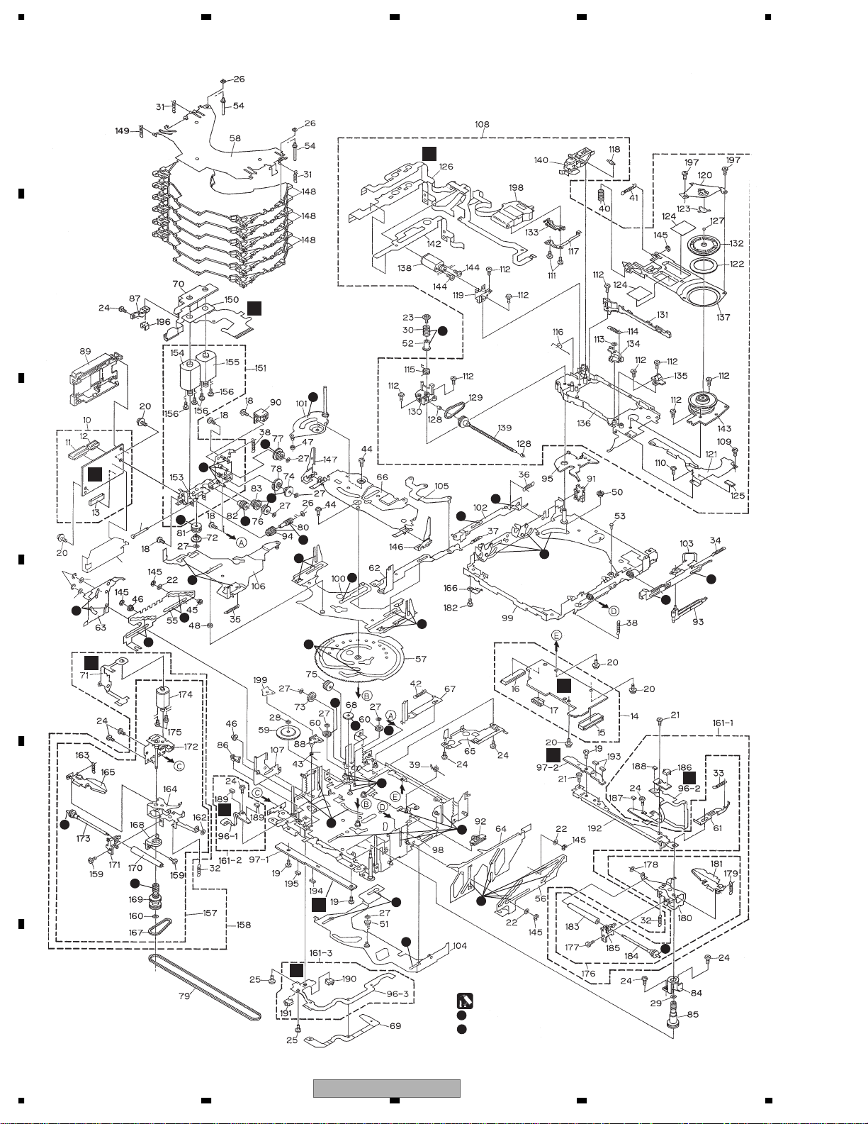
2.3 CD MECHANISM
A
B
E
F
2
1
2
C
145
D
C
49
141
22
22
1
1
2
2
2
1
1
2
2
1
1
1
2
1
1
1
1
1
K
D
2
2
2
G
2
L
E
1
1
1
J
2
I
1
1
1
1
H
1
F
10
1234
CDX-MG6047ZH/UC
:GEM1024
2
:GEM1035

5678
CD MECHANISM SECTION PARTS LIST
Mark No. Description Part No.
1-9 •••••
10 CD Core Unit(Servo Unit) CWX2202
11 Connector(CN101) CKS2764
12 Connector(CN301) CKS3966
13 Connector(CN201) CKS3991
14 CD Core Unit(STS Unit) CWX2203
15 Connector(CN701) CKS3989
16 Connector(CN801) CKS3989
17 Connector(CN802) CKS4054
18 Screw(M2x2.5) CBA1651
19 Screw(M2x2.5) CBA1041
20 Screw(M2x2.5) CBA1624
21 Screw(M2x2) CBA1250
22 Washer CBA1529
23 Screw(M2x2.5) CBA1452
24 Screw(M2x1.9) CBA1453
25 Screw(M2x2) CBA1479
26 Washer CBF1037
27 Washer CBF1038
28 Washer CBF1039
29 Washer CBF1064
30 Spring CBH2007
31 Spring CBH2520
32 Spring CBH2274
33 Spring CBH2014
34 Spring CBH2015
35 Spring CBH2016
36 Spring CBH2017
37 Spring CBH2290
38 Spring CBH2366
39 Spring CBH2064
40 Spring CBH2195
41 Spring CBH2196
42 Spring CBH2224
43 Spring CBH2250
44 Screw CBA1082
45 Roller CLA3154
46 Roller CLA3157
47 Roller CLA3159
48 Roller CLA3160
49 Shaft CLA3179
50 Spacer CLA3194
51 Roller CLA3248
52 Bush CLA3353
* 53 Shaft CLA3469
54 Shaft CLA3693
55 Steer CNC7215
56 Steer CNC7216
57 Cam CNC8774
56
No. Description Part No.
Mark
58 Holder CNC7235
59 Gear CNC7236
60 Gear CNC9512
61 Lever CNC7243
62 Lever CNC7244
63 Lever CNC7245
64 Lever Unit CXB4944
65 Cover CNC7441
66 Holder Unit CXB4946
67 Lever CNC9088
68 Gear CNC8140
69 Sheet CNM6840
70 PCB CNP5680
71 PCB CNP5681
72 Gear CNR1479
73 Gear CNR1481
74 Gear CNR1495
75 Gear CNR1501
76 Gear CNR1502
77 Gear CNR1540
78 Gear CNR1541
79 Belt CNT1080
80 Worm Gear CNV6807
81 Gear CNV5047
82 Gear CNV5048
83 Gear CNV5049
84 Holder CNV5056
85 Pulley CNV5058
86 Arm CNV5061
87 Spacer CNV5066
88 Arm CNV6595
89 Cover CNV5207
90 Cover CNV6808
91 Cover CNV5425
92 Lever CNV5427
93 Arm CNV5491
94 Gear CNV5519
95 Holder CNV5648
* 96 Composite PCB CNX3557
97 Composite PCB CNX2989
98 Chassis Unit CXB5938
99 Frame Unit CXC1923
100 Lever Unit CXB6026
101 Arm Unit CXB7533
102 Lever Unit CXB2708
103 Lever Unit CXB7070
104 Lever Unit CXB4949
105 Arm Unit CXB2712
106 Lever Unit CXB9086
CDX-MG6047ZH/UC
7
8
A
B
C
D
E
F
11

1234
No. Description Part No.
Mark
107 Lever Unit CXB2714
108 Carriage Mechanism Unit(G1) CXB5639
A
109 Screw(M2x2.2) CBA1604
110 Screw(M2x2) CBA1250
111 Screw(M2x3.8) CBA1362
112 Screw(M2x2.4) CBA1471
113 Washer CBF1038
No. Description Part No.
Mark
157 Loading Arm L Assy CXC2575
158 Load Arm L Assy(Service) CXX1747
159 Screw(M2x1.9) CBA1453
160 Washer CBF1038
161 Load Arm R Assy(Service) CXX1748
162 Washer CBF1074
163 Spring CBH2690
114 Spring CBH2008
115 Spring CBH2009
116 Spring CBH2010
117 Spring CBL1335
B
C
D
118 Roller CLA3913
* 119 Bracket CNC7228
120 Guide Unit CXB4417
121 Cover CNC9504
122 Sheet CNM6414
123 Sheet CNM5378
124 Sheet CNM5695
125 Sheet CNM5827
126 PCB CNP6164
127 Ball CNR1189
128 Bearing CNR1423
129 Belt CNT1079
130 Holder CNV5037
131 Guide CNV5040
132 Clamper CNV5042
133 Rack CNV5111
134 Arm CNV5579
135 Holder CNV5759
136 Chassis Unit CXB8450
137 Arm Unit CXB2705
138 Motor Unit(M4 CARRIAGE) CXC1389
* 164 Arm CNC7241
* 165 Arm CXC2573
166 Holder CBL1508
167 Belt CNT1079
168 Holder CNV5055
169 Pulley CNV5057
170 Roller CNV6209
171 Guide CNV5125
* 172 Bracket Unit CXB5937
173 Roller Gear Unit CXB3176
* 174 Motor Unit(M2 LOAD) CXC1388
175 Screw JFZ14P020FZK
176 Loading Arm R Assy CXC2576
177 Screw(M2x1.9) CBA1453
178 Washer CBF1074
179 Spring CBH2690
* 180 Arm CNC7242
* 181 Arm CXC2574
182 Screw JFZ20P014FTC
183 Roller CNV6209
184 Roller Gear Unit CXB3176
185 Guide CNV5126
186 Switch(S885 MAX) CSN1052
187 LED(D883) CL205IRXTU
188 Photo-transistor(Q881) CPT231SCTD
139 Screw Unit CXB3179
140 Lever Unit CXB4450
141 Insulator CNM6306
142 Spacer CNM6345
143 Motor(M5 SPINDLE) CXM1279
E
F
144 Screw JFZ14P020FZK
145 Washer YE15FTC
146 Arm Unit CXB5018
147 Arm Unit CXB5019
148 Tray Assy CXB7656
149 Spring CBH2519
150 Sheet CNM7109
151 Cam Motor Assy CXB7636
152 •••••
* 153 Bracket Unit CXB4165
* 154 Motor Unit(M1 Cam Gear) CXC1392
* 155 Motor Unit(M3 ELV) CXC1386
156 Screw JFZ20P025FTC
12
1234
189 LED(D891,892) CL205IRXTU
190 Switch(S887 CLAMP) CSN1051
191 Switch(S886 ELV HOME) CSN1052
192 Bracket Unit CXB6086
193 Photo-transistor(Q851,852) CPT231SCTD
194 Resistor(R856) RS1/8S911J
195 Resistor(R857) RS1/8S821J
196 Photo-interrupter(Q1) RPI-221
197 Screw(M2x1.4) CBA1687
198 Pickup Unit(Service)(P8) CXX1311
199 Sheet CNM7791
CDX-MG6047ZH/UC

5678
A
B
C
D
E
56
CDX-MG6047ZH/UC
F
7
8
13
N
C
V
D
X
L
R
P
D
C
O
V
1234
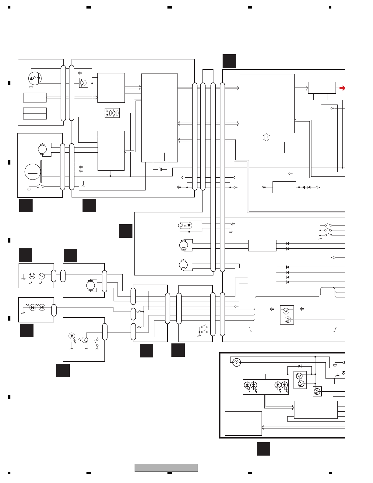
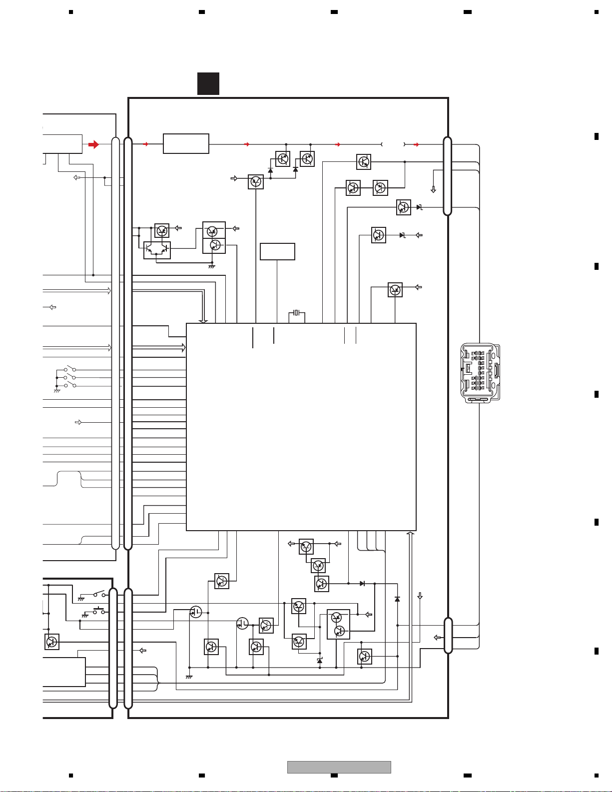
3. BLOCK DIAGRAM AND SCHEMATIC DIAGRAM
3.1 BLOCK DIAGRAM
A
PICKUP UNIT(P8)(SERVICE)
MD
LD+
HOLOGRAM
UNIT
FOCUS ACT
LD
LD-
FO+
TO+
MD
TRACKING ACT
B
CARRIAGE
MOTOR
M
SPINDLE
MOTOR
BCL
SWITCH
HOME
VCC
ST/SR
GND
HOME
VM
EC
C
E C
MOTOR PCB(B)
PCB UNIT(D)
G
Q852
Q851
1
D
1
D892
D891
L
PCB UNIT(A)
E
J
F
CN101
5
14
V5
15
Q101
4
3
16
PD
17
LD
UPC2572GS
RF AMP
IC 101
Q102
CD 4CH DRIVER
14
11
BVD
V5
16
15
22
IC 301
BA5986FM
MUTE
9
1
2
3
4
8
5
6
7
10
11
CN301
CD CORE UNIT(SERVO UNIT)
D
MOTOR PCB(A)
LOAD MOTOR PCB
K
PH1
M
S885
MAX
SWITCH
PVD
PH2
3
2
1
4
1
2
1
LOADING
MOTOR
D883
Q881
PCB UNIT(C)
69
EFM
UPD63702AGF
35
DIGITAL SERVO
PROCESSOR
DIGITAL SIGNAL
PROCESSOR
MD/SD/TD/FD
µ-COMPUTER
INTERFACE
VR2
10
74
F
PH1
3
2
1
1
MAXSW
4
1
2
I
PCB UNIT(E)
IC 201
XTAL
X201
PVD
PH2
XTAL
11
ELEVATION
SENSE
CAMGEAR
MOTOR
ELEVATION
MOTOR
5
6
3
PH1
4
2
1
CN201 CN801
WDCK
RFCK
RAOV
LRCK
SCKO
DOUT
MCK
CONT
19
28
5V
29
VD
30
M
M
LD MOTOR-
5
LD MOTOR+
6
3
4
2
1
ELV HOME
S886
S887
CLAMP
PCB UNIT(B)
H
19
28
29
30
PVD
PH1
PH2
MAXSW
19
28
29
30
36
35
37
32
33
39
41
5
7
3
4
2
1
10
11
CD CORE UNIT(STS UNIT)
D
19
28
5V
29
30
VD
ELVSNS
45
PVD
44
46
MOTOR DRIVER
41
43
48
50
7
5
9
8
10
11
2
1
CGCG+
ELEL+
LOLO+
ELHOME
CLAMP
3
5
MOTOR DRIVER
3
5
12
10
PVD
CN802
KEY MATRIX
S901-906
BCK
DATA
SHOCKPROOF
CONTROLLER
IC 501
CXD2511R
IC 502
MSM514400DP-60TS
LRCK
XTLI
4M DRAM
VM
5V REGULATOR
4
PVD
Q802
IC 701
BA05SFP
1
2
6
2
6
13
9
Q801
19
KST1-KST3/KD1,KD2
V+5V
XAO/XSTB/XSO/XSI/XSCK/XRST/SCONT
IC 802
LB1836M
IC 801
LB1836M
D905-916
8fs DF D/A LPF
39
2
S801
VD
LOAD
Q903
Q904
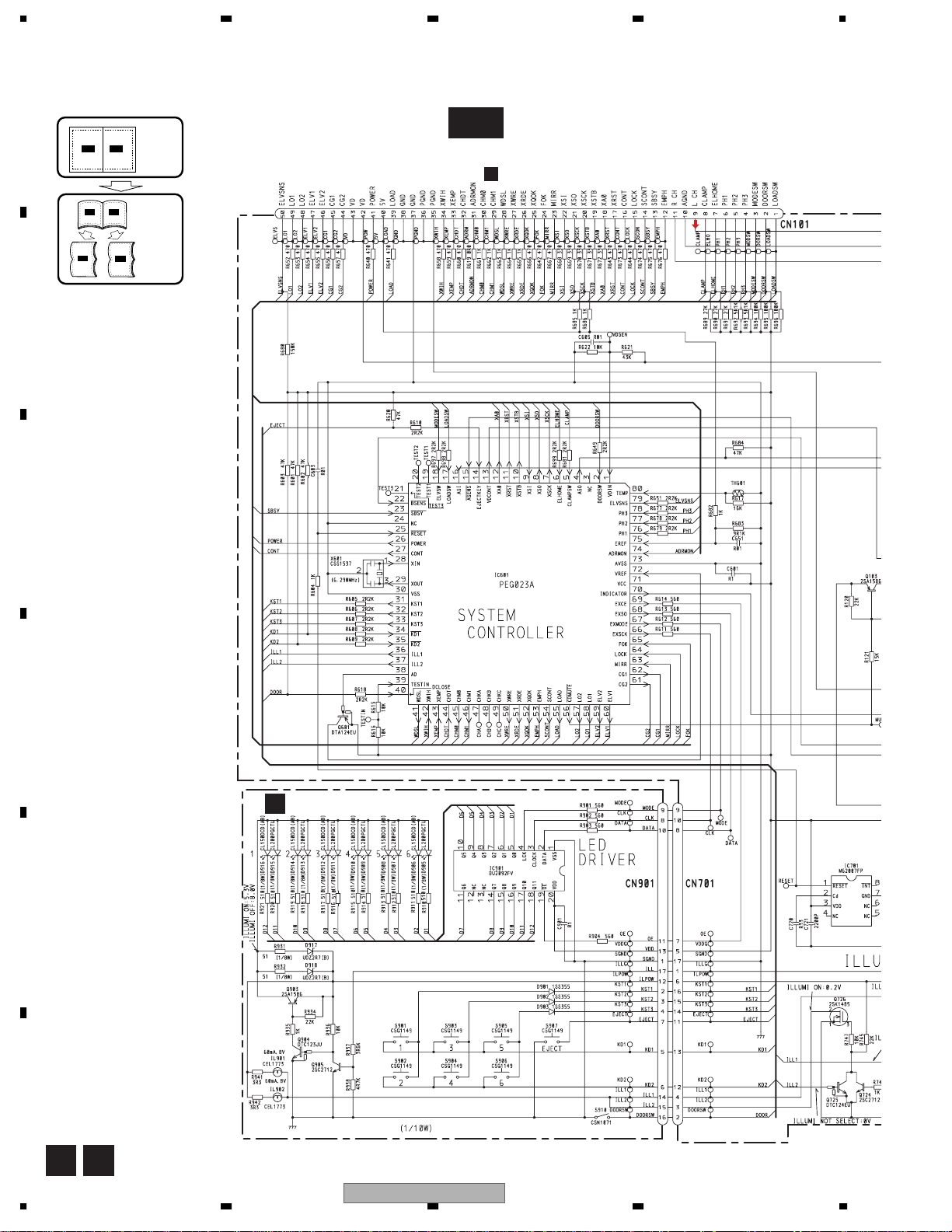
LED DRIVER
IC901
BU2092FV
oe
IC 601
AK4321VF
512
WDSL/CHMO/CHMI
S802
S803
Q905
18
6
PD
DEMO
VD
XWRE/XRDE/XQOK
XWIH/XEMP/ADRMON/CHDT
VD
V+5V
EJECT
20
VDD
DATA
CLOCK
LCK
EL
LOA
DOO
MOD
MA
ELH
DOO
2
3
4
CN
C
E
PO
CL
IL
M
14
KEYBOARD UNIT
B
CDX-MG6047ZH/UC
1234
IT)
5678
A
A
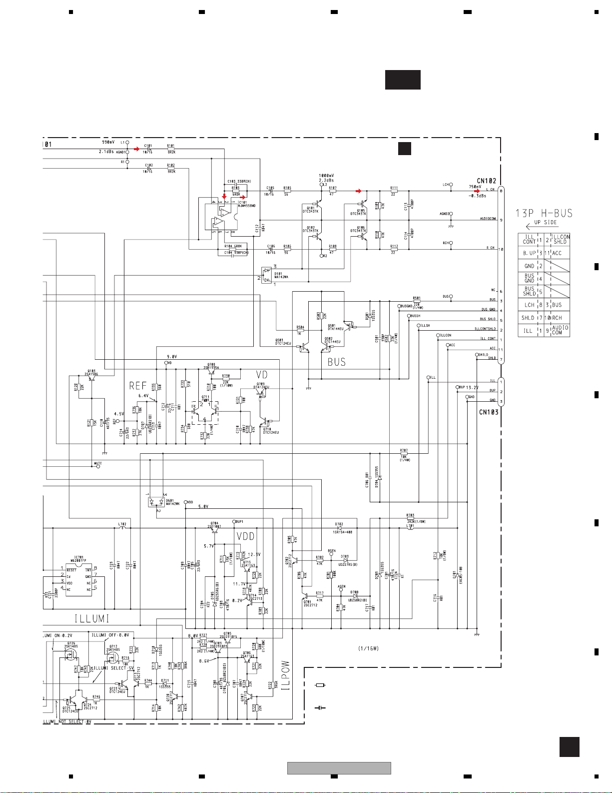
CONTROL UNIT
s DF D/A LPF
IC 601
AK4321VF
12
WDSL/CHMO/CHMI
ONT
801
802
803
Q905
RIVER
01
2FV
1,KD2
18
6
PD
DEMO
VD
XWRE/XRDE/XQOK
XWIH/XEMP/ADRMON/CHDT
VD
V+5V
EJECT
20
VDD
DATA
CLOCK
LCK
CN701
LCH
CONT
EMPH
POWER
ELVSNS
LOADSW
DOORSW
MODESW
CG1
CG2
ELV1
ELV2
LO1
LO2
MAXSW
PH2
PH1
LOAD
ELHOME
CLAMP
DOORSW
ILL1
ILL2
ILL
VDD
2
DATA
3
CLK
4
MODE
OE
CN901
2
NJM4558MD
Q708
CHDT
CLAMP
Q711
LPF
IC101
BUP
26
79
17
2
18
62
61
64
63
65
60
59
58
57
78
77
76
75
55
6
5
Q726
1
VDD
Q709
Q710
53
POWER
EMPH
ELVSNS
LOADSW
DOORSW
ELVSW
CG1
CG2
LOCK
MIRR
FOK
ELV1
ELV2
LO1
LO2
PH3
PH2
PH1
EREF
LOAD
ELHOME
CLAMPSW
DCLOSE
401437 36
Q725
ILL
Q724
KEY DATA
VDD
VDCONT
27
13
CONT
VDCONT
EJECTKEY
ILL2
Q712
Q103
RESET
IC701
M62007FP
56
CDMUTE
Q723
Q713
Q101
1
CD MUTE
Q105
X601
(6.29MHz)
25
28
29
XIN
XOUT
RESET
SYSTEM
CONTROLLER
IC601
PEG023A
ILL1
Q704
VDD
Q715
Q705
Q703
KST1-KST3/KD1,KD2
Q502
16
4
15
ASI
ASO
70
BUP
Q714
ILL POWER
Q706
Q707
Q503
BSENS
ASENS
INDICATOR
69
BSENS
Q702
72 38
22
VREF
BSENS
EXCE
EXSO
686667
OE
DATA
BUP
Q720
Q501
ASENS
EXSCK
CLK
CD-LCH
ASENS
Q601
EXMODE
MODE
Q701
AD
CN102
VDD
A
ILL CONT
BUP
ILL
BUP
LCH
BUS
A
ACC
GND
CONT
ILL
8
3
1
11
H-BUS
1
2
3
CN103
B
C
13P
D
E
F
CN101
9
42
LCH
VD
8
9
VD REGULATOR
VD
43
42
CONT
16
35
EMPH
39
12
WDSL/CHM0/CHM1
XWRE/XRDE/XQOK
XWIH/XEMP/ADRMON
POWER
10
41
ELVSNS
1
50
LOADSW
50
1
DOORSW
49
2
MODESW
48
3
CG1
45
6
CG2
44
7
LOCK
15
MIRR
23
11
FOK
24
ELV1
47
4
ELV2
46
5
LO1
2
49
LO2
48
3
PH3
47
4
PH2
5
46
PH1
6
45
40
LOAD
ELHOME
12
39
7
44
43
8
DOOR
2
16
ILPOWILPOW
12
6
EJECT
7
11
ILL1
14
4
ILL2
15
3
ILL
17
1
13
5
VDD
DATA
10
8
CLK
10
8
MODE
9
9
OE
7
11
CN701
IT
56
CDX-MG6047ZH/UC
7
8
15
1234
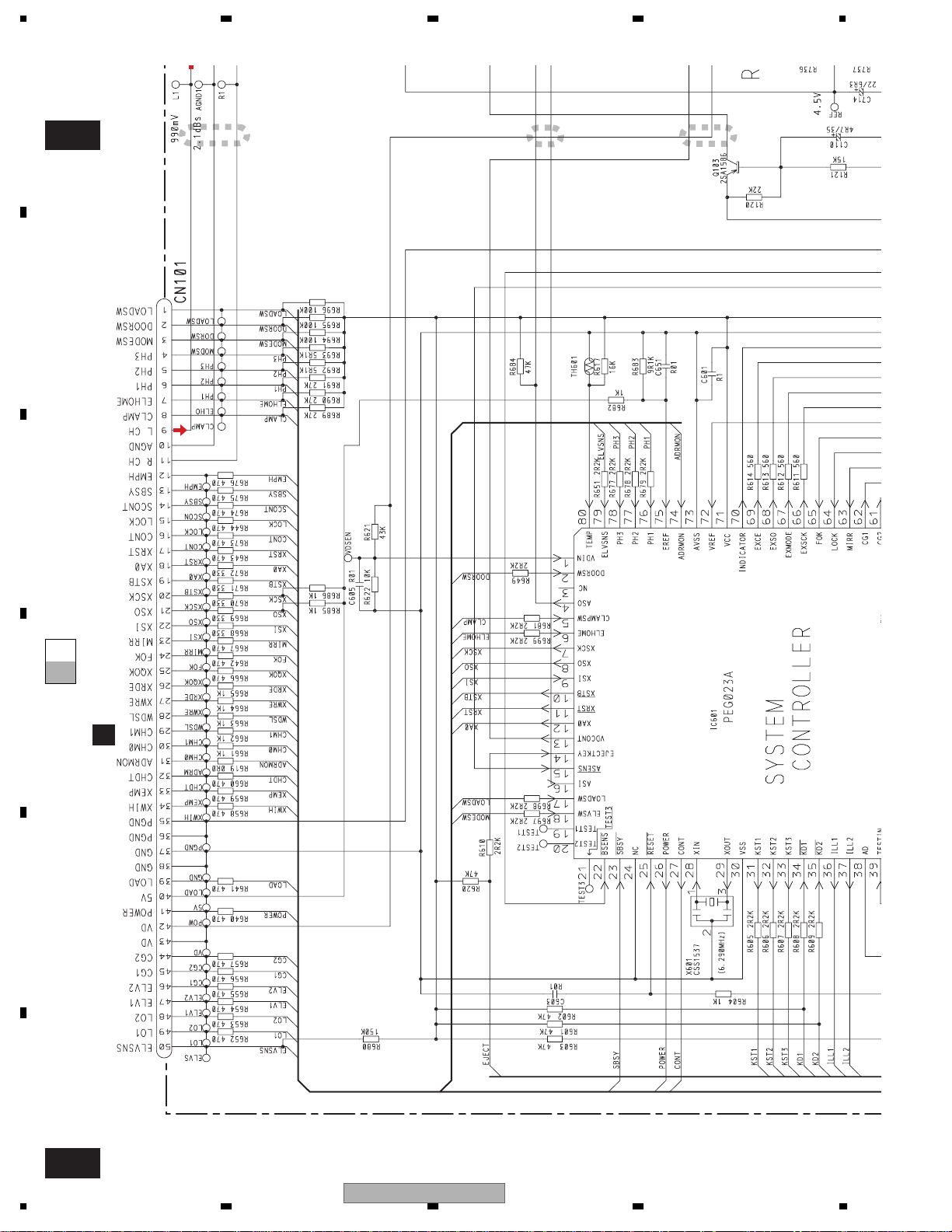
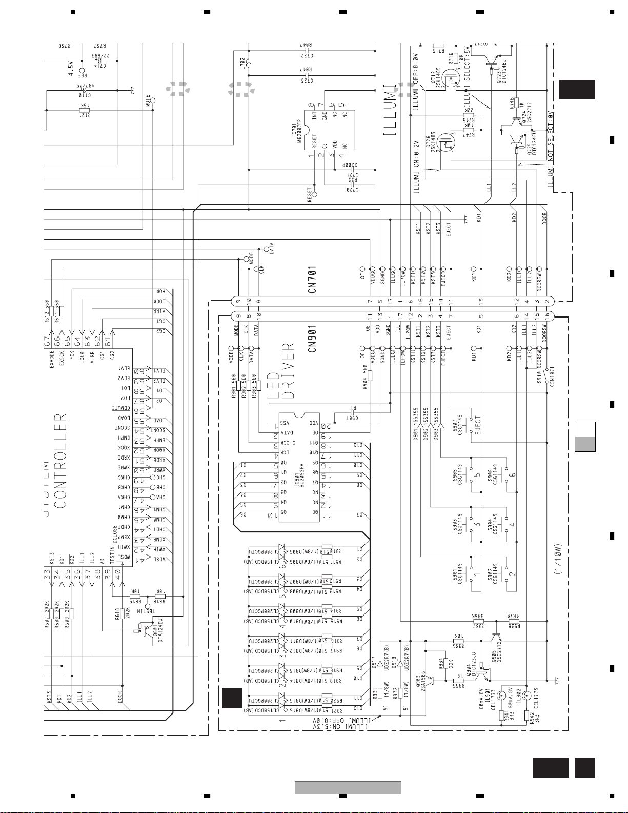
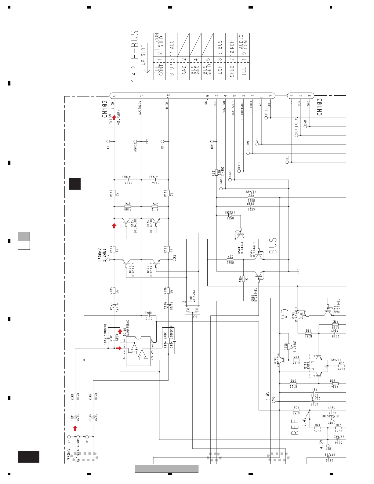
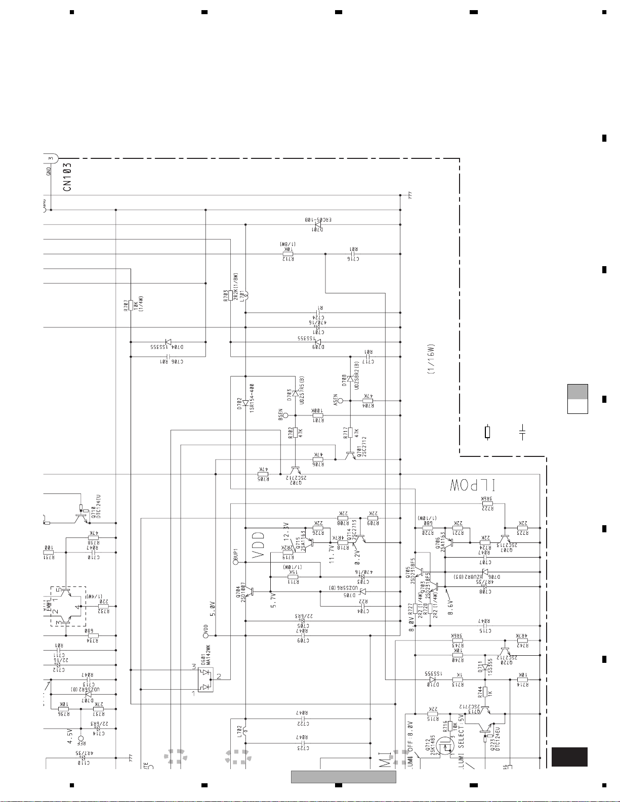
3.2 OVERALL CONNECTION DIAGRAM(GUIDE PAGE)
Note: When ordering service parts, be sure to refer to " EXPLODED VIEWS AND PARTS LIST" or
"ELECTRICAL PARTS LIST".
A
A-a
D
CN701
A-a A-b
A-a
A-b
Large size
SCH diagram
Guide page
A-b
Detailed page
A-a
B
C
D
KEYBOARD UNIT
B
E
F
A B
16
1234
CDX-MG6047ZH/UC
5678
A
A-b
CONTROL UNIT
A
B
C
D
E
NOTE :
Symbol indicates a resistor.
No differentiation is made between chip resistors and
discrete resistors.
Symbol indicates a capacitor.
No differentiation is made between chip capacitors and
discrete capacitors.
CDX-MG6047ZH/UC
56
Decimal points for resistor
and capacitor fixed values
are expressed as :
←
2.2 2R2
←
0.022 R022
F
A
7
8
17
A
B
A-b
1234
1
2 3
C
A-b
A-a
A-a
D
CN701
D
E
F
A-a
18
1234
CDX-MG6047ZH/UC
5678
A
4
5
6
A-b
B
A-b
A-a
A-a
C
D
E
KEYBOARD UNIT
B
CDX-MG6047ZH/UC
56
F
A-a
7
8
B
19
1234
A
B
CONTROL UNIT
A
C
A-b
A-a
D
E
F
A-b
20
1
CDX-MG6047ZH/UC
1234
2 3
5678
A
←
←
Decimal points for resistor
and capacitor fixed values
are expressed as :
2.2 2R2
0.022 R022
B
C
A-b
Symbol indicates a resistor.
No differentiation is made between chip resistors and
discrete resistors.
Symbol indicates a capacitor.
No differentiation is made between chip capacitors and
discrete capacitors.
A-a
NOTE :
D
E
4
5
CDX-MG6047ZH/UC
56
F
6
7
8
A-b
21
 Loading...