

Pioneer CDX-MG6246ZH, CDX-MG6036ZH Service Manual

PIONEER ELECTRONIC CORPORATION 4-1, Meguro 1-Chome, Meguro-ku, Tokyo 153-8654, Japan
PIONEER ELECTRONICS SERVICE INC. P.O.Box 1760, Long Beach, CA 90801-1760 U.S.A.
PIONEER ELECTRONIC [EUROPE] N.V. Haven 1087 Keetberglaan 1, 9120 Melsele, Belgium
PIONEER ELECTRONICS ASIACENTRE PTE.LTD. 253 Alexandra Road, #04-01, Singapore 159936
C PIONEER ELECTRONIC CORPORATION 1999
K-ZZB. JUNE 1999 Printed in Japan
ORDER NO.
CRT2390
6 DISC IN-DASH CD CHANGER
CDX-MG6246ZH CA
HONDA
VEHICLE DESTINATION PRODUCED AFTER PART No. ID No. PIONEER MODEL No.
Not specified CANADA June 1999 08A06-3B3-3000 CDX-MG6246ZH/CA
- This service manual should be used together with the following manual(s):
Model Order No. Mech. Module Remarks
CDX-MG6036ZH/US CRT2351
EXPLODED VIEWS AND PARTS LIST
PACKING (Page 3)
- PACKING SECTION PARTS LIST
Part No.
Mark No. Description CDX-MG6036ZH/US CDX-MG6246ZH/CA
5 Owner's Manual CRB1553 CRD3055
11 Carton CHG3764 CHG3838
12 Contain Box CHL3764 CHL3838

PIONEER ELECTRONIC CORPORATION 4-1, Meguro 1-Chome, Meguro-ku, Tokyo 153-8654, Japan
PIONEER ELECTRONICS SERVICE INC. P.O.Box 1760, Long Beach, CA 90801-1760 U.S.A.
PIONEER ELECTRONIC [EUROPE] N.V. Haven 1087 Keetberglaan 1, 9120 Melsele, Belgium
PIONEER ELECTRONICS ASIACENTRE PTE.LTD. 253 Alexandra Road, #04-01, Singapore 159936
C PIONEER ELECTRONIC CORPORATION 1999
K-ZZB. JUNE 1999 Printed in Japan
ORDER NO.
CRT2351
6 DISC IN-DASH CD CHANGER
6 DISC IN-DASH CD CHANGER
CDX-MG6036ZH US
HONDA
CONTENTS
1. SAFETY INFORMATION ............................................2
2. EXPLODED VIEWS AND PARTS LIST.......................3
3. BLOCK DIAGRAM AND SCHEMATIC DIAGRAM...10
4. PCB CONNECTION DIAGRAM ................................26
5. ELECTRICAL PARTS LIST ........................................42
6. ADJUSTMENT..........................................................46
7. GENERAL INFORMATION .......................................48
7.1 DIAGNOSIS ........................................................48
7.1.1 TEST MODE..............................................48
7.1.2 DISASSEMBLY .........................................53
7.1.3 CONNECTOR FUNCTION DESCRIPTION.......57
7.2 IC ........................................................................58
8. OPERATIONS AND SPECIFICATIONS.....................63
VEHICLE DESTINATION PRODUCED AFTER PART No. ID No. PIONEER MODEL No.
Not specified U.S.A. June 1999 08A06-3B1-3000 CDX-MG6036ZH/US
- This service manual should be used together with the following manual(s):
Model Order No. Mech. Module Remarks
CX-890 CRT2376 G1 CD Mechanism Module:Circuit Description, Mechanism Description, Disassembly
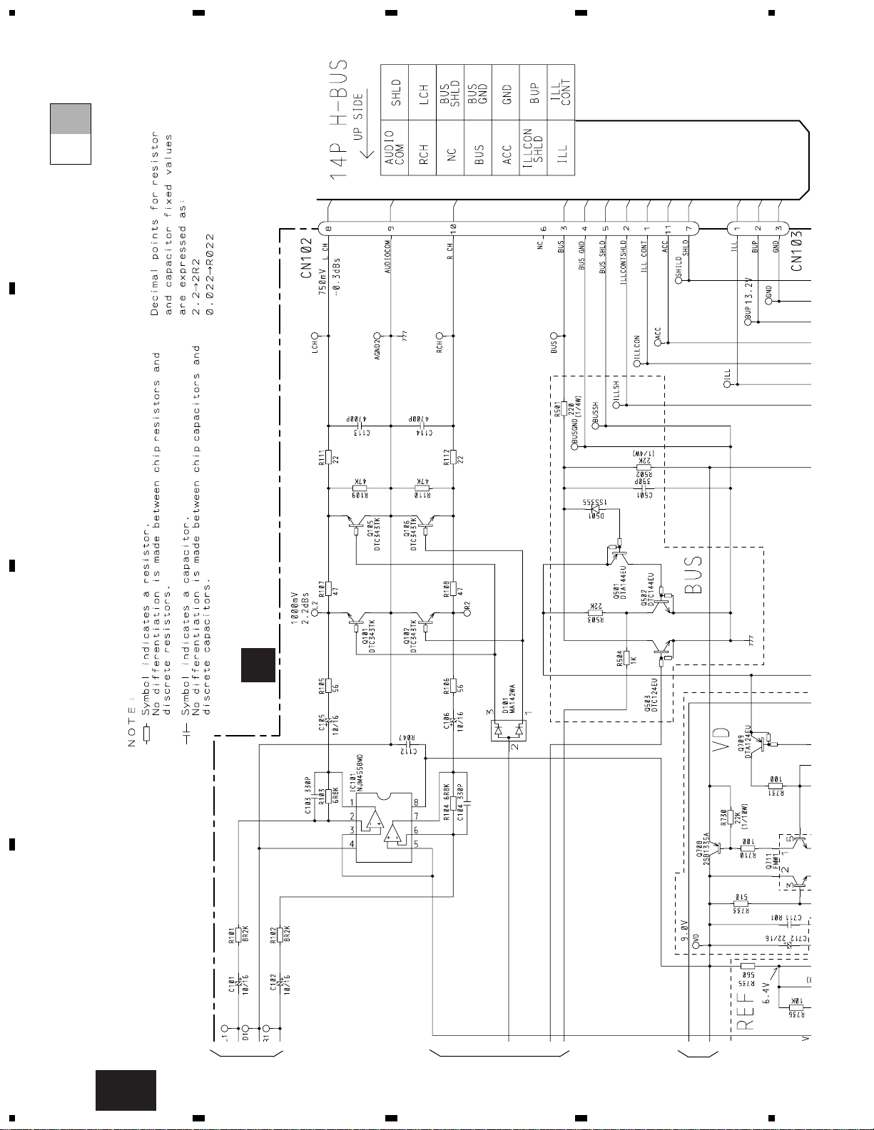
- To operate this product, a 14-pin H-BUS head unit is required.
When performing adjustments, connect the 8-pin/14-pin conversion jig (GGD1163) to a Pioneer 8-pin H-
BUS head unit. You can use it in place of a 14-pin H-BUS head unit.
2
CDX-MG6036ZH
- CD Player Service Precautions
1. For pickup unit(CXX1311) handling, please refer
to"Disassembly"(see page 53).
During replacement, handling precautions shall be
taken to prevent an electrostatic discharge(protection
by a short pin).
2. During disassembly, be sure to turn the power off
since an internal IC might be destroyed when a connector is plugged or unplugged.
3. Please checking the grating after changing the service pickup unit(see page 46).
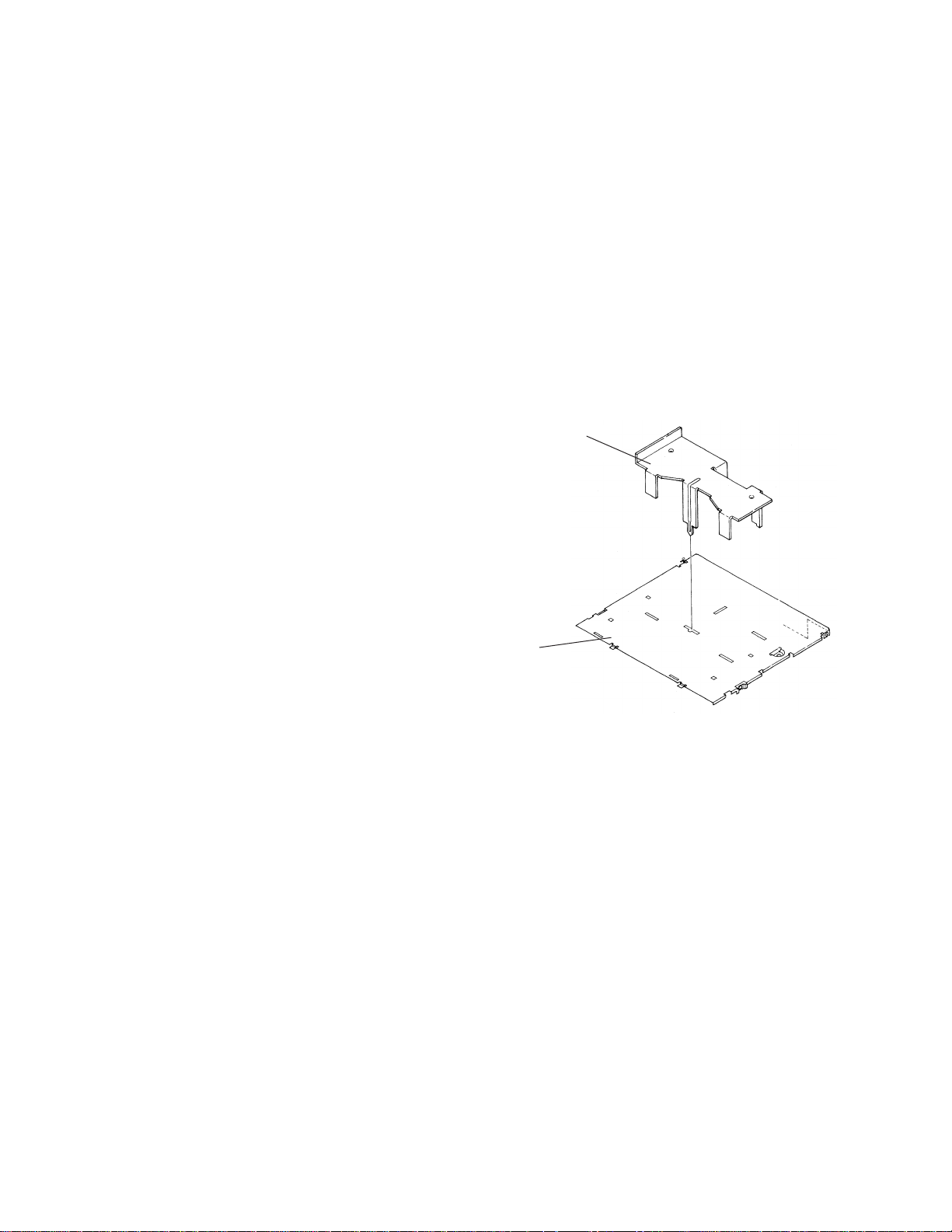
- When the Repair is Complete
When the repair is complete, make the CD mechanism
ready for transportation implementing the following
procedures:
1. Press the changer side 1 and 4 simultaneously to turn
the ACC on.
2. As the ACC is turned on, the disc indicator blinks in
red.
3. When the blinking is stopped, the mechanism is
ready for the transportation.
4. Attach the Transportation Bracket (CNC7878). Now
you can transport it.(See the figure below)
This service manual is intended for qualified service technicians; it is not meant for the casual do-it-yourselfer.
Qualified technicians have the necessary test equipment and tools, and have been trained to properly and safely repair
complex products such as those covered by this manual.
Improperly performed repairs can adversely affect the safety and reliability of the product and may void the warranty.
If you are not qualified to perform the repair of this product properly and safely; you should not risk trying to do so
and refer the repair to a qualified service technician.
1. SAFETY INFORMATION
Transportation Basket
(CNC7878)
Case
(CNB2354)

CDX-MG6036ZH
1 Screw Assy CEA2565
* 2 Polyethylene Bag CEG-127
3 Screw HMF40P060FZK
4 Screw HMF50P080FMC
5 Owner’s Manual(English) CRB1553
6 Spacer CNM6551
* 7 Sheet CHW1402
8 Protector CHP2123
* 9 Polyethylene Bag E36-609
10 Protector CHP2124
11 Carton CHG3764
12 Contain Box CHL3764
13 Clamper CNV4042
* 14 Band CNF-512
15 Polyethylene Bag CEG1116
Mark No. Description Part No. Mark No. Description Part No.
- PACKING SECTION PARTS LIST
NOTE:
- Parts marked by “*” are generally unavailable because they are not in our Master Spare Parts List.
- Screws adjacent to
∇ mark on the product are used for disassembly.
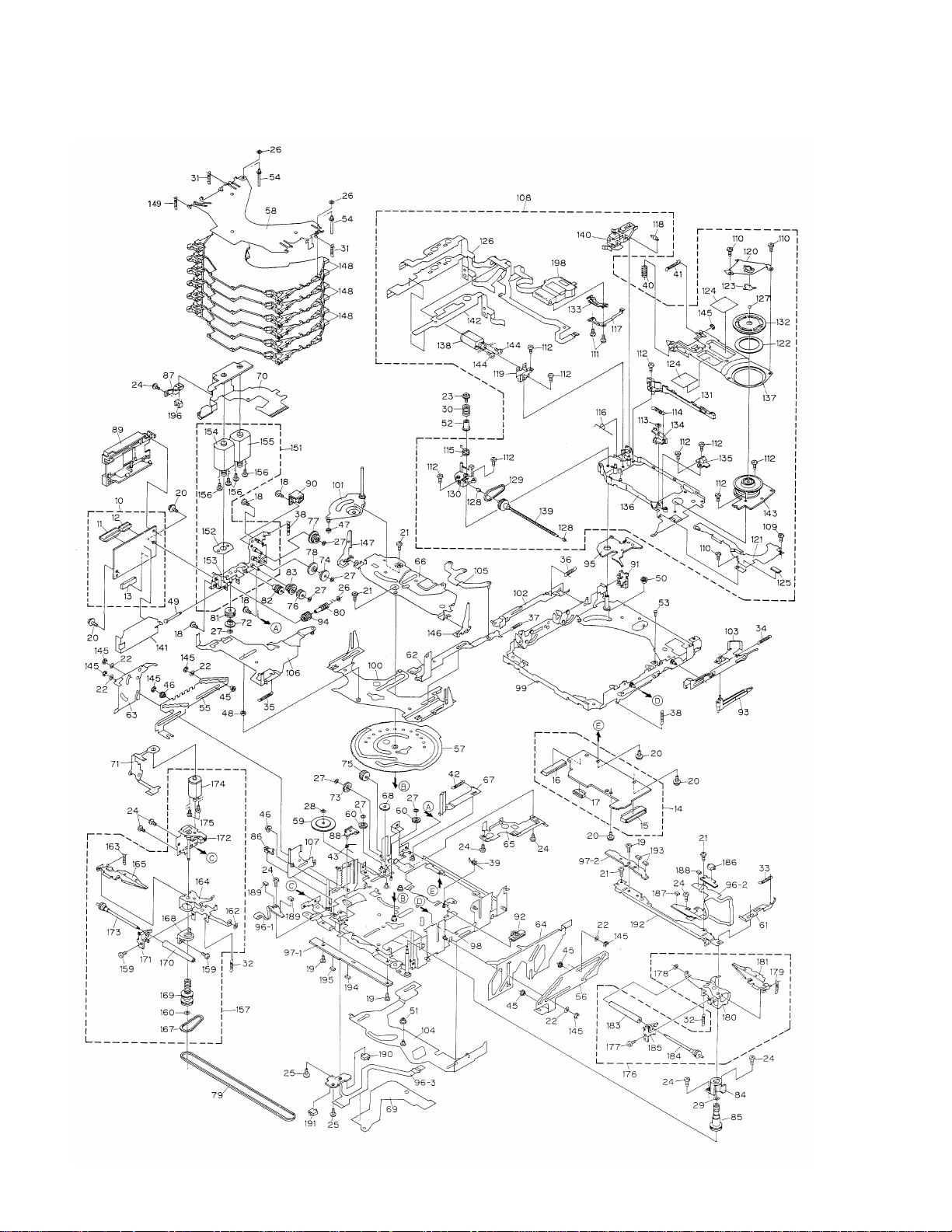
2. EXPLODED VIEWS AND PARTS LIST
2.1 PACKING
3

4
CDX-MG6036ZH
2.2 EXTERIOR

CDX-MG6036ZH
1 Screw BMZ20P020FMC
2 Screw BMZ26P030FMC
3 Screw BMZ26P060FMC
4 Chassis Unit CXB3407
5 Case CNB2354
6 Side Frame CNB2397
7 Bracket CNC7878
8 Bracket CNC8026
9 Front Frame CNC8110
10 Holder CNC8111
11 Insulator CNM5969
12 Insulator CNM6112
13 PCB CNP5516
14 Insulator CNM6409
15 Holder CNV5543
* 16 Caution Label CRP1200
17 Extension Unit CWM6288
18 Cord CDE6055
19 Connector(CN102) CKS2200
20 Connector(CN103) CKS3597
21 Connector(CN701) CKS3785
22 Connector(CN101) CKS3989
23 Holder CNC8031
24 Screw BPZ20P060FMC
25 Button CAC5864
26 Button CAC5865
27 Door CAT2003
28 Washer CBF1038
29 Spring CBH2201
30 Spring CBH2200
31 Conductor CNC8051
32 Lighting Conductor CNV5901
33 Gear CNV5547
34 Arm CNV5548
35 Guide CNV5880
36 Sheet CNM6318
37 Double Faced Tape CNM6424
38 Insulator CNM6512
39 PCB CNP5373
40 Bracket Unit CXB3111
41 Grille Unit CXB3409
42 Screw IMS20P040FMC
43
CD Mechanism Module(G1) CXK4702
44 Screw IMS20P040FMC
45 Screw IMS26P040FMC
46 Cushion CNV5674
47 Keyboard Unit CWM6289
48 Transistor(Q708) 2SB1335A
49 Damper CNV5120
50 Holder CNC7826
51 Screw CBA1250
52 Sheet CNM5981
53 Connector(CN901) CKS3785
54 Screw IMS26P030FZK
55 Holder CNC7477
56 Spring(Left Rear) CBH2065
57 Spring(Right Rear)(Black) CBH2067
58 Spring(Front) CBH2066
- EXTERIOR SECTION PARTS LIST
Mark No. Description Part No.
Mark No. Description Part No.
5
6
CDX-MG6036ZH
2.3 CD MECHANISM

7
CDX-MG6036ZH
1-9 •••••
10 CD Core Unit(Servo Unit) CWX2202
11 Connector(CN101) CKS2764
12 Connector(CN301) CKS3966
13 Connector(CN201) CKS3991
14 CD Core Unit(STS Unit) CWX2203
15 Connector(CN701) CKS3989
16 Connector(CN801) CKS3989
17 Connector(CN802) CKS4054
18 Screw CBA1037
19 Screw CBA1041
20 Screw CBA1076
21 Screw CBA1250
22 Screw CBA1405
23 Screw CBA1452
24 Screw CBA1453
25 Screw CBA1479
26 Washer CBF1037
27 Washer CBF1038
28 Washer CBF1039
29 Washer CBF1064
30 Spring CBH2007
31 Spring CBH2271
32 Spring CBH2274
33 Spring CBH2014
34 Spring CBH2015
35 Spring CBH2016
36 Spring CBH2017
37 Spring CBH2290
38 Spring CBH2019
39 Spring CBH2064
40 Spring CBH2195
41 Spring CBH2196
42 Spring CBH2224
43 Spring CBH2250
44 •••••
45 Roller CLA3154
46 Roller CLA3157
47 Roller CLA3159
48 Roller CLA3160
49 Shaft CLA3179
50 Spacer CLA3194
51 Roller CLA3248
52 Bush CLA3353
* 53 Shaft CLA3469
54 Shaft CLA3693
55 Steer CNC7215
56 Steer CNC7216
57 Cam CNC7227
* 58 Holder CNC7235
59 Gear CNC7236
60 Gear CNC7238
61 Lever CNC7243
62 Lever CNC7244
63 Lever CNC7245
64 Lever CNC7246
65 Cover CNC7441
66 Holder CNC8613
67 Lever CNC8024
68 Gear CNC8140
69 Sheet CNM5831
70 PCB CNP5680
71 PCB CNP5681
72 Gear CNR1479
73 Gear CNR1481
74 Gear CNR1495
75 Gear CNR1501
76 Gear CNR1502
77 Gear CNR1540
78 Gear CNR1541
79 Belt CNT1080
80 Worm Gear CNV5046
81 Gear CNV5047
82 Gear CNV5048
83 Gear CNV5049
84 Holder CNV5056
85 Pulley CNV5058
86 Arm CNV5061
87 Spacer CNV5066
88 Arm CNV5189
89 Cover CNV5207
90 Cover CNV5424
91 Cover CNV5425
92 Lever CNV5427
93 Arm CNV5491
94 Gear CNV5519
95 Holder CNV5648
96 Composite PCB CNX3141
97 Composite PCB CNX2989
98 Chassis Unit CXB4314
- CD MECHANISM SECTION PARTS LIST
Mark No. Description Part No.
Mark No. Description Part No.

8
CDX-MG6036ZH
99 Frame Unit CXB2702
100 Lever Unit CXB2703
101 Arm Unit CXB2704
102 Lever Unit CXB2708
103 Lever Unit CXB2709
104 Lever Unit CXB2711
105 Arm Unit CXB2712
106 Lever Unit CXB2713
107 Lever Unit CXB2714
108
Carriage Mechanism Unit(G1) CXB2998
109 Screw CBA1041
110 Screw CBA1250
111 Screw CBA1362
112 Screw CBA1471
113 Washer CBF1038
114 Spring CBH2008
115 Spring CBH2009
116 Spring CBH2010
117 Spring CBL1335
118 Roller CLA3707
* 119 Bracket CNC7228
120 Guide Unit CXB4417
121 Cover CNC7628
122 Sheet CNM6414
123 Sheet CNM5378
124 Sheet CNM5695
125 Sheet CNM5827
126 PCB CNP4978
127 Ball CNR1189
128 Bearing CNR1423
129 Belt CNT1079
130 Holder CNV5037
131 Guide CNV5040
132 Clamper CNV5042
133 Rack CNV5111
134 Arm CNV5579
135 Holder CNV5759
* 136 Chassis CXB2698
137 Arm Unit CXB2705
138
Motor Unit(M4 CARRIAGE) CXB3178
139 Screw Unit CXB3179
140 Lever Unit CXB4450
141 Insulator CNM6306
142 Spacer CNM6345
143 Motor(M5 SPINDLE) CXM1120
144 Screw JFZ14P020FMC
145 Washer YE15FUC
146 Arm Unit CXB4953
147 Arm Unit CXB4954
148 Tray Assy CXB4307
149 Spring CBH2269
150 •••••
151 Cam Motor Assy CXB3170
152 Spacer CNC8289
* 153 Bracket Unit CXB4165
* 154
Motor Unit(M1 Cam Gear) CXB3174
* 155 Motor Unit(M3 ELV) CXB3175
156 Screw JFZ20P025FMC
157 Loading Arm L Assy CXB3171
158 •••••
159 Screw CBA1453
160 Washer CBF1038
161 •••••
162 Washer CBF1074
163 Spring CBH2136
* 164 Arm CNC7241
* 165 Arm CXB4449
166 •••••
167 Belt CNT1079
168 Holder CNV5055
169 Pulley CNV5057
170 Roller CNV5064
171 Guide CNV5125
* 172 Bracket Unit CXB4316
173 Roller Gear Unit CXB3176
174 Motor Unit(M2 LOAD) CXB3177
175 Screw JFZ14P020FMC
176 Loading Arm R Assy CXB3172
177 Screw CBA1453
178 Washer CBF1074
179 Spring CBH2136
* 180 Arm CNC7242
* 181 Arm CXB4448
182 •••••
183 Roller CNV5064
184 Roller Gear Unit CXB3176
185 Guide CNV5126
186 Switch(S885 MAX) CSN1052
187 LED(D883) CL202IRXTU
188 Photo-transistor(Q881) CPT230SCTD(CD)
Mark No. Description Part No.
Mark No. Description Part No.

9
CDX-MG6036ZH
Mark No. Description Part No.
189 LED(D891,892) CL202IRXTU
190 Switch(S887 CLAMP) CSN1051
191 Switch(S886 ELV HOME) CSN1052
192 Bracket Unit CXB4306
193
Photo-transistor(Q851,852) CPT230SCTD(CD)
194 Resistor(R856) RS1/8S911J
195 Resistor(R857) RS1/8S821J
196 Photo-interrupter(Q1) RPI-221
197 •••••
198 Pickup Unit(Service)(P8) CXX1311

10
CDX-MG6036ZH
1
23
4
1234
D
C
B
A
PICKUP UNIT(SERVICE)
MOTOR PCB(B)
MOTOR PCB(A)
CD CORE UNIT(SERVO UNIT)
PCB UNIT(D)
PCB UNIT(A)
PCB UNIT(C)
PCB UNIT(E)
PCB UNIT(B)
LOAD MOTOR PCB
CD CORE UNIT
HOLOGRAM
UNIT
FOCUS ACT
TRACKING ACT
MD
LD+
LD-
LD
MD
FO+
TO+
16
17
V5
Q101
Q102
PD
LD
CN101
IC101
UPC2572GS
RF AMP
IC201
UPD63702AGF
DIGITAL SERVO
PROCESSOR
DIGITAL SIGNAL
PROCESSOR
µ-COMPUTER
INTERFACE
35
69
EFM
CD 4CH DRIVER
IC301
BA5986FM
14
11
16
15
22
BVD
V5
MUTE
9
MD/SD/TD/FD
74
10
11
VR2
XTAL
XTAL
X201
5V
VD
CONT
CN201 CN801
5V
VD
CN301
WDCK
RFCK
RAOV
LRCK
SCKO
DOUT
MCK
IC501
CXD2511R
SHOCKPROOF
CONTROL
BC
DAT
LRC
XT
IC502
MSM514400DP-60TS
4M DRAM
V+5V
IC701
BA05SFP
5V REGULAT
VM
4
1
XAO/XSTB/XSO/XSI/
MOTOR DRIVER
IC802
LB1836M
2
6
3
5
ELVSNS
MOTOR DRIVER
LB1836M
IC801
2
6
13
9
5
3
12
10
CGCG+
ELEL+
PVD
LOLO+
PVD
PVD
Q801
Q802
CLAMP
ELHOME
CN802
M
BCL
SPINDLE
MOTOR
CARRIAGE
MOTOR
HOME
SWITCH
EC
VM
VCC
ST/SR
GND
HOME
M
LOADING
MOTOR
M
CAMGEAR
MOTOR
M
ELEVATION
MOTOR
Q851
Q852
D891
D892
PH1
PVD
Q881
D883
PH2
S883
MAX
SWITCH
PH1
PVD
PH1
PH2
MAXSW
LD MOTOR-
LD MOTOR+
MAXSW
PH2
PH1
PVD
ELV HOME
S886
S887
CLAMP
ELEVATION
SENSE
KEYBO
KEY MATRIX
D905~916
5
14
15
4
3
1
2
3
4
8
5
6
7
10
11
1
1
1
1
2
3
4
1
2
4
1
2
1
1
2
3
5
6
3
4
2
1
5
6
3
4
2
1
5
7
3
4
2
1
7
5
9
8
10
11
10
2
11
1
19
28
29
30
19
28
29
30
45
44
46
36
35
37
32
33
39
41
41
43
48
50
B
E
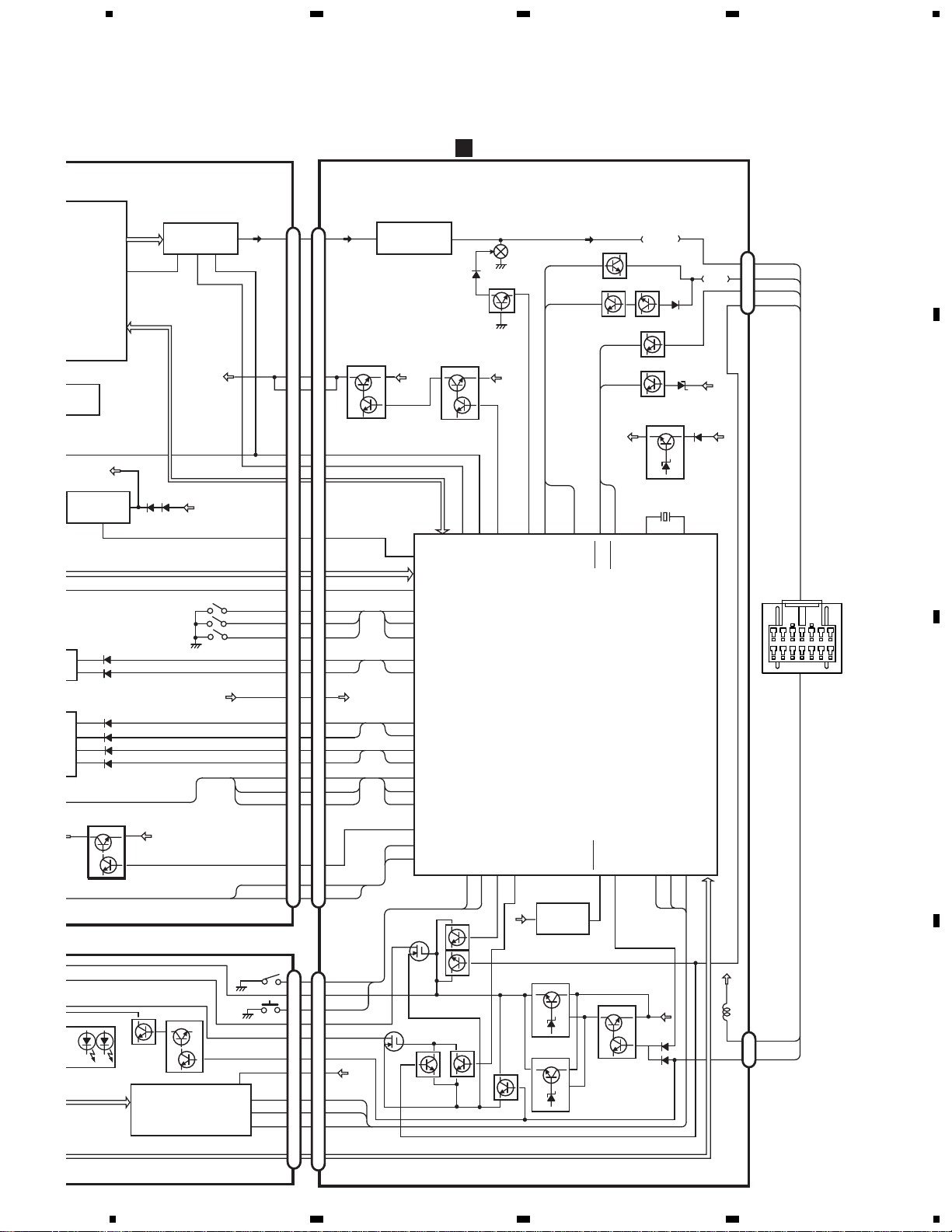
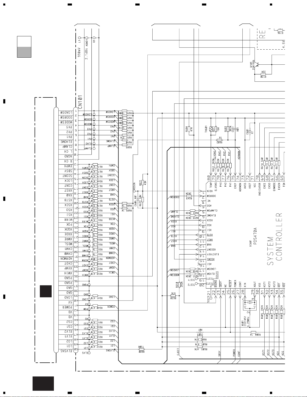
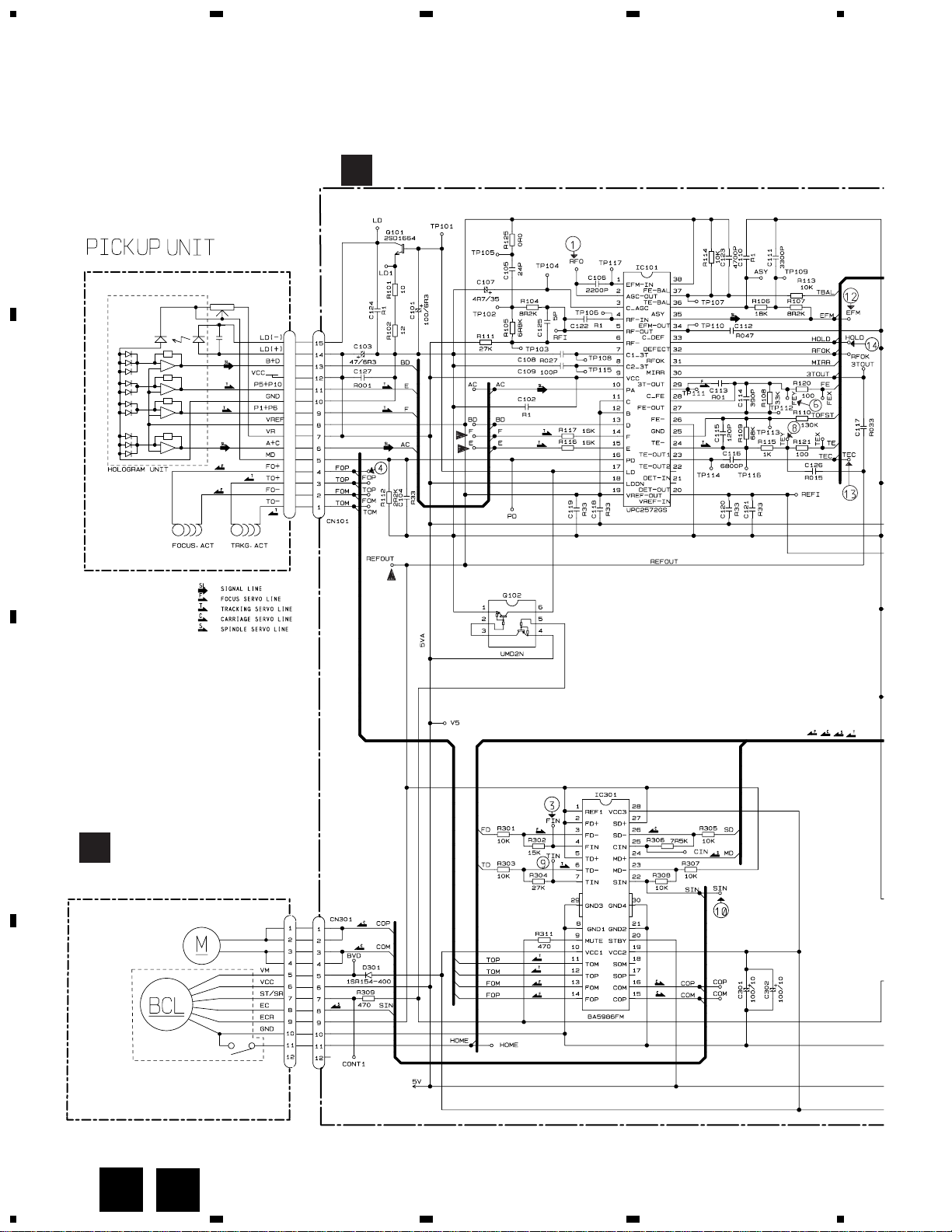
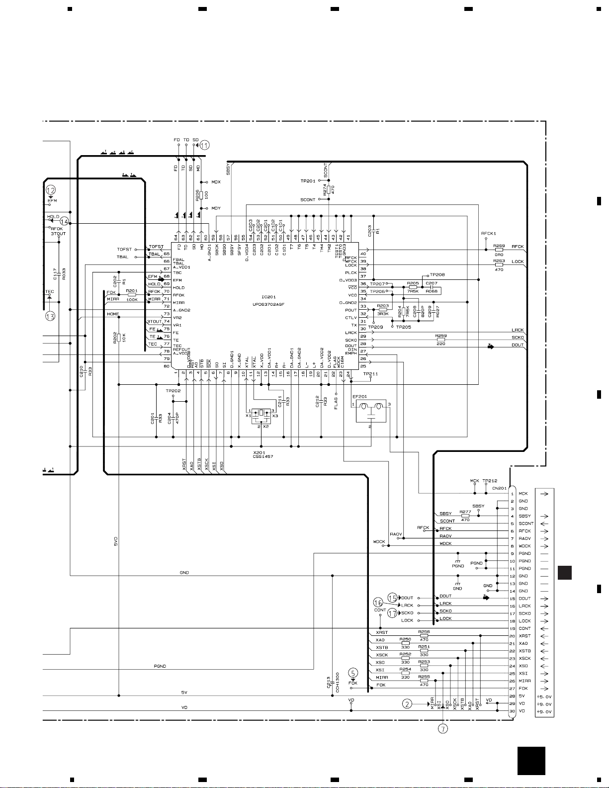
3. BLOCK DIAGRAM AND SCHEMATIC DIAGRAM
3.1 BLOCK DIAGRAM
F
H
IJK
G
L
D
C
11
CDX-MG6036ZH
5
6
78
5
6
78
D
C
B
A
BCK
DATA
LRCK
XTLI
39
512
IC601
AK4321VF
8fs DF D/A LPF
CN701
CN101
6
18
DEMO
PD
P-60TS
M
VD
VD
LCH
WDSL/CHMO/CHMI
XWRE/XRDE/XQOK
XWIH/XEMP/ADRMON/CHDT
IC701
BA05SFP
REGULATOR
VM
VD
POWER
CONT
EMPH
2
1
TB/XSO/XSI/XSCK/XRST/SCONT
ELVSNS
LOADSW
DOORSW
MODESW
S801
S802
S803
2
6
2
6
13
9
CG1
CG2
ELV1
ELV2
LO1
LO2
MAXSW
PH2
PH1
Q801
VD
LOAD
LOAD
ELHOME
CLAMP
ELVSNS
V+5V
V+5V
KEYBOARD UNIT
EXTENSION UNIT
NJM4558MD
IC101
LPF
VD REGULATOR
VDD
B.U
VDD
B.U
WDSL/CHMO/CHMI
XWRE/XRDE/XQOK
XWIH/XEMP/ADRMON
CHDT
PD5470A
SYSTEM
CONTROLLER
IC601
M62007FP
IC701
RESET
ILL POWER
VDD REGULATOR
CD MUTE
CN102
LCH
2
1
53
27
13
56
4
16
15 22
28
29
Q101
Q103
ASO
ASI
Q503
Q502 Q501
CD-LCH
BUS
ASENS
BSENS
VDCONT
Q709
Q708
Q710
Q704
X601
Q701
Q702
ASENB
B.U
ILL CONT
ASO
ASO
ASI
ASI
Q711
XOUT
XIN
BSENS
ASENS
CDMUTE
VDCONT
CONT
EMPH
EXMODE
POWER
LOADSW
DOORSW
ELVSW(MODESW)
CG1
CG2
ELV1
ELV2
LO1
LO2
PH3
PH2
PH1
LOAD
ELHOME
CLAMPSW
26
79
17
2
18
62
61
60
59
58
57
78
77
76
55
6
5
DCLOSE
EJECTKEY
ILL1
ILL2
RESET
INDICATOR
EXSO
EXCSK
DATA
EXCK
401436 37
25
70
686667
3
1
VDD
Q723
Q713
Q712
Q705
Q706
B.U
Q707
Q703
Q720
Q725
Q726
Q724
B.U
ILL
CN701
CN901
CN103
KEY DATA
DOORSW
DOORSW
ILPOWILPOW
EJECT
EJECT
ILL1
ILL1
ILL2
ILL2
ILL
ILL
VDD
VDD
DATA
CLK
MODE
LED DRIVER
IC901
BU2092FV
Q904
Q903
Q905
16
20
2
3
4
H-BUS
14P
42
8
9
9
43
42
35 16
39
12
10 41
1
50
49
48
50
1
2
3
6
7
45
44
11 40
4
47
5
46
2
49
3
48
47
46
45
4
5
6
12 39
44
7
43
8
16
12
7
14
15
17
13
10
8
9
9
10
8
5
1
3
4
11
6
2
1
2
1
11
3
8
A

12
CDX-MG6036ZH
1
23
4
1234
D
C
B
A
CD CORE UNIT (STS UNIT)
C
KEYBOARD UNIT
B
27K
27K
2K
1
2
3
456
7
8
9
10
11
12
13
14
15
161718
19
20
21
22
23
24
25
26
27
28
29
30
31
32
33
34
35
36
37
38
39
40
41
42
43
44
45
46
47
484950
CN701
A
3.2 OVERALL CONNECTION DIAGRAM(GUIDE PAGE)
Note: When ordering service parts, be sure to refer to “EXPLODED VIEWS AND PARTS LIST” or “ELECTRICAL PARTS
LIST”.
A-a A-b
A-a
A-b
A-b
A-a
Large size
SCH diagram
Guide page
Detailed page
B
A-a

13
CDX-MG6036ZH
5
6
78
5
6
78
D
C
B
A
EXTENSION UNIT
A
15K
A-b
A
14
CDX-MG6036ZH
1
23
4
1234
D
C
B
A
CD CORE UNIT (STS UNIT)
C
27K
27K
2K
1
2
3
4
5
6
7
8
9
10
11
12
13
14
15
16
17
18
19
20
21
22
23
24
25
26
27
28
29
30
31
32
33
34
35
36
37
38
39
40
41
42
43
44
45
46
47
48
49
50
CN701
A-a
1
2
3
A-a
A-b

15
CDX-MG6036ZH
5
6
78
5
6
78
D
C
B
A
KEYBOARD UNIT
B
A-a
A-b
B
A-a
4
16
CDX-MG6036ZH
1
23
4
1234
D
C
B
A
EXTENSION UNIT
A
A-b
A-a
A-b
1
2
3

17
CDX-MG6036ZH
5
6
78
5
6
78
D
C
B
A
15K
A-b
A-a
A-b
4
18
CDX-MG6036ZH
1
23
4
1234
D
C
B
A
3.2 CD CORE UNIT(SERVO UNIT)
C
E
(SERVICE)
M5 SPINDLE
CXM1120
DISC INSERT DETECT
M4 CARRIAGE
CXB3178
2.5V
RF AMP/
AUTO POWER
CONTROL
CD DRIVER
D
E
MOTOR PCB(B)
CD CORE UNIT(SERVO UNIT)
C
19
CDX-MG6036ZH
5
6
78
5
6
78
D
C
B
A
C
16.934MHz
22/6R3
FOCUS/TRACKING
CARRIAGE/SPINDLE
DIGITAL SERVO
DIGITAL SIGNAL PROCESSOR
D/A CONVERTER
F

M1 : CXB3174
Q1 : RPI-221
M3 : CXB3175
SURE TRACK
MEMORY CONTRO
+5V REGULATOR
7.5V
9.0V
MOTOR DRIVER
G
F
D
H
LOAD SWITCH
DOOR SWITCH
MODE SWITCH
CD CORE UNIT(STS UNIT)
CD CORE UNIT
(SERVO UNIT)
MOTOR PCB
(A)
ELV SENSE
20
CDX-MG6036ZH
1
23
4
1234
D
C
B
A
3.3 CD CORE UNIT(STS UNIT)
D
F
D
C

21
CDX-MG6036ZH
5
6
78
5
6
78
D
C
B
A
22/6R3
RY CONTROLLER
MOTOR DRIVER
4M DRAM
D/A CONVERTER
A
CN101
D

22
CDX-MG6036ZH
1 RFO 0.5V/div. 0.2µs/div.
Normal mode: play
1 CH1: RFO 1V/div.
2 CH2: MIRR 5V/div.
Test mode: Tracking open
0.5ms/div.
1 CH1: RFO 1V/div.
2 CH2: MIRR 5V/div.
Normal mode: The defect part
passes 500µs/div.
0.5ms/div.
3 CH1: FIN 0.5V/div.
4 CH2: FOP 2V/div.
Test mode: No disc, Focus close
0.2s/div.
3 CH1: FIN 0.5V/div.
5 CH2: FOK 2V/div.
Normal mode: Focus close
0.2s/div.
6 CH1: FEY 0.5V/div.
7 CH2: XSI 2V/div.
Normal mode: Focus close
1ms/div.
8 CH1: TEY 0.5V/div.
9 CH2: TIN 0.5V/div.
Test mode: 32 tracks jump (FWD)
0.5ms/div.
8 CH1: TEY 0.5V/div.
9 CH2: TIN 0.5V/div.
Test mode: Single jump (FWD)
0.5ms/div.
6 CH1: FEY 0.1V/div.
3 CH2: FIN 0.2V/div.
Normal mode: Play
20ms/div.
3 CH1: FIN 0.5V/div.
0 CH2: SIN 1V/div.
Normal mode: Focus close
0.5s/div.
GND
→
GND
→
GND
→
GND
→
- Waveforms
0 SIN 0.5V/div. 0.1s/div.
Normal mode: Play
REFOUT
→
REFOUT
→
REFOUT
→
REFOUT
→
REFOUT
→
REFOUT
→
REFOUT
→
REFOUT
→
REFOUT
→
REFOUT
→
REFOUT
→
REFOUT
→
REFOUT
→
REFOUT
→
REFOUT
→
REFOUT
→
1 RFO 0.5V/div. 0.5µs/div.
Test mode
REFOUT
→
REFOUT
→
REFOUT
→
Note:1. The encircled numbers denote measuring pointes in the circuit diagram.
2. Reference voltage
REFOUT:2.5V

23
CDX-MG6036ZH
3 CH1: FIN 1V/div.
$ CH2: HOLD 5V/div.
Normal mode:
The defect part passes 800µm
8 CH1: TEY 0.5V/div.
6 CH2: FEY 0.1V/div.
Normal mode: AGC after focus close
8 CH1: TEY 0.5V/div.
! CH2: SD 0.5V/div.
5ms/div.
0 SIN 1V/div. 10ms/div.
Long Search
8 CH1: TEY 1V/div.
# CH2: TEC 1V/div.
Test mode: Focus close
Tracking open
2ms/div.
6 CH1: FEY 0.2V/div.
3 CH2: FIN 0.5V/div.
Normal mode: During
AGC
1ms/div.
@ EFM 1V/div. 2µs/div.
Play
0.2s/div.
% Dout 2V/div. 5µs/div.
Play
^ LRCK 2V/div. 10µs/div. * ADRMON 1V/div. 1s/div.
Normal mode: Starting play
GND
→
REFOUT
→
REFOUT
→
REFOUT
→
REFOUT
→
REFOUT
→
REFOUT
→
REFOUT
→
REFOUT
→
REFOUT
→
REFOUT
→
REFOUT
→
REFOUT
→
REFOUT
→
REFOUT
→
1 CH1: RFO 1V/div.
$ CH2: HOLD 5V/div.
Normal mode:
The defect part passes 800µm
500µs/div.
REFOUT
→
REFOUT
→
8 CH1: TEY 0.2V/div.
9 CH2: TIN 0.5V/div.
Normal mode: During
AGC
1ms/div.
REFOUT
→
REFOUT
→
GND
→
GND
→
500µs/div.

24
CDX-MG6036ZH
8 CH1: TEY 0.5V/div.
9 CH2: TIN 0.5V/div.
Test mode: 100 tracks jump(FWD)
8 CH1: TEY 0.5V/div.
9 CH2: TIN 0.5V/div.
Normal mode: Play
10ms/div.
5ms/div.
REFOUT
→
REFOUT
→
& SCKO 2V/div. 500ns/div.
Play
REFOUT
→
) CH1: RCH 2V/div.
( CH2: LCH 2V/div.
Normal mode: PLAY (0dB,1kHz)
200µs/div.
AAGND
→
AAGND
→
REFOUT
→
REFOUT
→

H
I
J
L
M
K
CXB3177
G
CN802
SWITCH
PCB UNIT(A)
PCB UNIT(C)
PCB UNIT(E)
PCB UNIT(B)
PCB UNIT(D)
LOAD MOTOR PCB
CPT230SCTD(CD)
CPT230SCTD(CD)
25
CDX-MG6036ZH
1
2
34
1
2
34
D
C
B
A
3.4 PCB UNIT(A,B,C,D,E), LOAD MOTOR PCB
L
I
H
G
J
K
G
D

26
CDX-MG6036ZH
1
23
4
1234
D
C
B
A
NOTE FOR PCB DIAGRAMS
1. The parts mounted on this PCB
include all necessary parts for
several destination.
For further information for
respective destinations, be sure
to check with the schematic diagram.
2. Viewpoint of PCB diagrams
A
EXTENSION UNIT
4. PCB CONNECTION DIAGRAM
4.1 EXTENSION UNIT
Capacitor
Connector
P.C.Board
Chip Part
SIDE A
SIDE B
SIDE A
CORD
A
 Loading...