

Pioneer CDX-M8067 Service Manual
ORDER NO.
CRT2711
PUB. NO. CRT2711
AUDIO SYSTEM
CD CHANGER
Manufactured for TOYOTA
by PIONEER CORPORATION
VEHICLE DESTINATION PRODUCED AFTER TOYOTA PART No. ID No. PIONEER MODEL No.
LEXUS ES300 U.S.A., AUSTRALIA July 2001 86270-33090 CDX-M8067ZT/E
ES300
2
CDX-M8067ZT
CDX-M8067ZT/E
CONTENTS
1. SAFETY INFORMATION ............................................3
2. EXPLODED VIEWS AND PARTS LIST.......................4
3. BLOCK DIAGRAM AND SCHEMATIC DIAGRAM ...10
4. PCB CONNECTION DIAGRAM ................................20
5. ELECTRICAL PARTS LIST ........................................26
6. ADJUSTMENT..........................................................29
7. GENERAL INFORMATION .......................................37
7.1 DIAGNOSIS .......................................................37
7.1.1 TEST MODE.............................................37
7.1.2 DIAGNOSIS CODE TABLE ......................41
7.1.3 DISASSEMBLY ........................................46
7.1.4 CONNECTOR FUNCTION DESCRIPTION ..48
7.2 IC ........................................................................49
7.3 EXPLANATION ..................................................51
7.3.1 OPERATIONAL FLOW CHART ................51
7.3.2 SYSTEM BLOCK DIAGRAM ...................52
8. OPERATIONS AND SPECIFICATIONS.....................52
- This service manual should be used together with the following manual(s):
Model No. Order No. Mech. Module Remarks
CX-652 CRT1857 C5 CD Mech. Module:Circuit Description, Mech.Description, Disassembly
3
CDX-M8067ZT
- CD Player Service Precautions
1. For pickup unit(CXX1235) handling, please refer
to"Disassembly"(see page 46).
During replacement, handling precautions shall be
taken to prevent an electrostatic discharge(protection
by a short pin).
2. During disassembly, be sure to turn the power off
since an internal IC might be destroyed when a con-
nector is plugged or unplugged.
3. Please checking the grating after changing the ser-
vice pickup unit(see page 31).
4. The doors CAT2248 and CAT2305 have been engaged
each other tightly. When you have to replace the
door CAT2248 or CAT2305, remove both doors from
the Grille to replace them at the same time.
1. SAFETY INFORMATION
This service manual is intended for qualified service technicians; it is not meant for the casual do-it-yourselfer.
Qualified technicians have the necessary test equipment and tools, and have been trained to properly and safely repair
complex products such as those covered by this manual.
Improperly performed repairs can adversely affect the safety and reliability of the product and may void the warranty.
If you are not qualified to perform the repair of this product properly and safely, you should not risk trying to do so
and refer the repair to a qualified service technician.
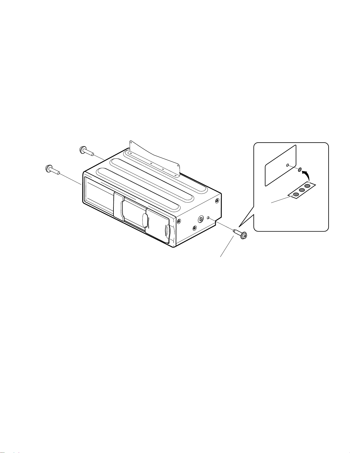
Seal
After removing transport screw,
cover the hole with the supplied
seal.
Transport screw
Attach to original position before
transporting the set.
- Transportation of multi-CD player
A transport screw has been attached to the set in order to protect it
during transportation. After removing the transport screw, cover the
hole with the supplied seal.Be sure to remove the transport screw
before mounting the set. The removed transport screw should be
retained in the accessory bag for use the next time the set is trans-
ported.
4
CDX-M8067ZT
19
17
16
18
15
14
13
12
9
6
5
4
3
2
1
7
8
10
11
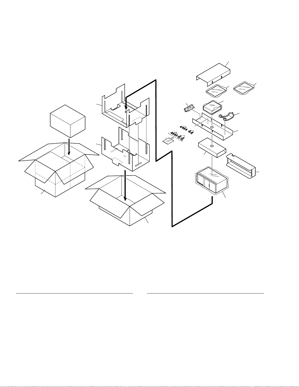
2. EXPLODED VIEWS AND PARTS LIST
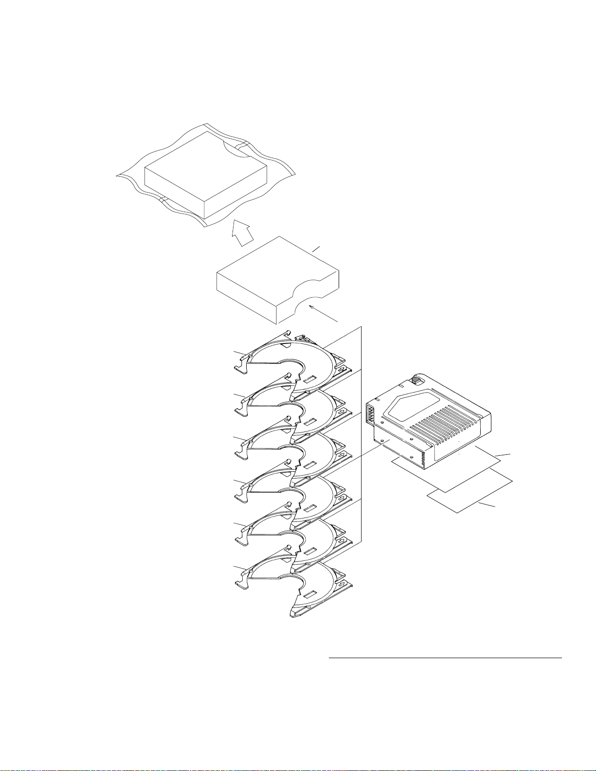
2.1 PACKING
NOTE:
- Parts marked by "*"are generally unavailable because they are not in our Master Spare Parts List.
- Screws adjacent to ∇ mark on the product are used for disassembly.
* 1 Polyethylene Bag CEG1171
2 93269-15014 CBA1564
3 91626-60818 CBA1563
4 90153-50010 CBA1566
5 91635-60616 CBA1565
6 Protector CHP2481
7-1 Owner’s Manual CRD3463
(English,French)
7-2 Polyethylene Bag CEG1116
8-1 Installation Manual CRD3484
(English)
8-2 Polyethylene Bag CEG1116
9 Magazine Assy CXB5850
10 86274-33220 CNC9747
11 86274-33210 CNC9746
12 Protector CHP2482
13 Protector CHP2376
14 Protector CHP2485
15 Polyethylene Bag CEG1174
16 Protector CHP2483
17 Protector CHP2484
18 Carton CHA3219
19 Contain Box CHL4517
Mark No. Description Part No. Mark No. Description Part No.
- PACKING SECTION PARTS LIST
5
CDX-M8067ZT
2.2 MAGAZINE ASSY
* 1 PP Case CNS6059
* 2 Owner's Manual CRD3236
* 3 Label CRW1365
4 Tray Unit CXB5983
- MAGAZINE ASSY SECTION PARTS LIST
Mark No. Description Part No.
1
4
4
4
2
4
3
4
4
6
CDX-M8067ZT
A
A
E
F
E
B
C
D
D
B
F
C
20
37
12
12
12
9
9
9
9
9
9
9
9
9
28
35
19
11
15
10
21
16
13
30
34
33
27
16
17
26
24
23
22
14
25
7
18
13
88
31
29
32
2
2
2
3
4
5
6
1
36
36
2
7
38
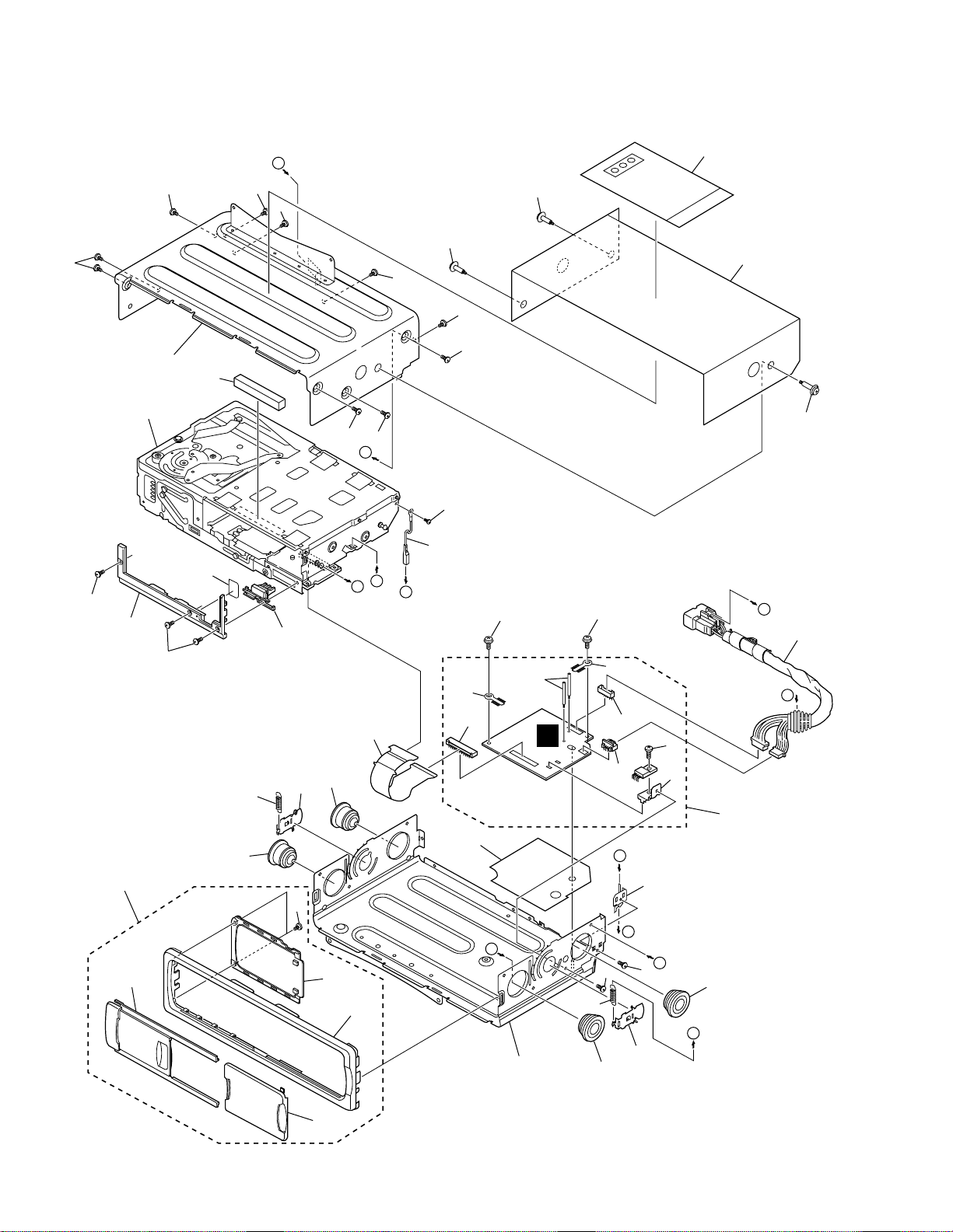
2.3 EXTERIOR
E

7
CDX-M8067ZT
1 Panel CNS5829
2 Damper CNV4501
3 Extension Unit CWX2585
4 Screw BMZ26P050FMC
5 Clamper CEF1008
6 Terminal(CN991) CKF1064
7 Screw IMS26P040FMC
8 Screw BMZ26P050FMC
9 Screw BMZ30P040FMC
10 Button CAC7015
11 Screw(M2x3) CBA1077
12 Screw CBA1352
13 Spring CBH1859
14 Cord CDE6621
15 Cord CDH1312
16 Arm CNC8058
17 Holder CNC9430
18 Insulator CNM7287
19 Cushion CNM7369
20-1 Seal CNM7435
20-2 Polyethylene Bag CEG1229
21 PCB CNP4402
22 Terminal(CN992) CKF1064
23 Plug(CN901) CKS-789
* 24 Plug(CN902) CKS1237
25 Connector(CN801) CKS2233
26 Holder CNC6743
27 Lower Case Unit CXB8000
28 Upper Case Unit CXB8001
29 Grille Assy CXB7337
30 Screw BPZ26P080FMC
31 Door CAT2248
32 Door CAT2305
33 Grille CNS6601
34 Panel CNS6602
35
CD Mechanism Module(C5) CXK4455
36 Screw IMS20P035FZK
* 37 Caution Card CRP1246
38 Seal CNM6552
- EXTERIOR SECTION PARTS LIST
Mark No. Description Part No.
Mark No. Description Part No.
8
CDX-M8067ZT
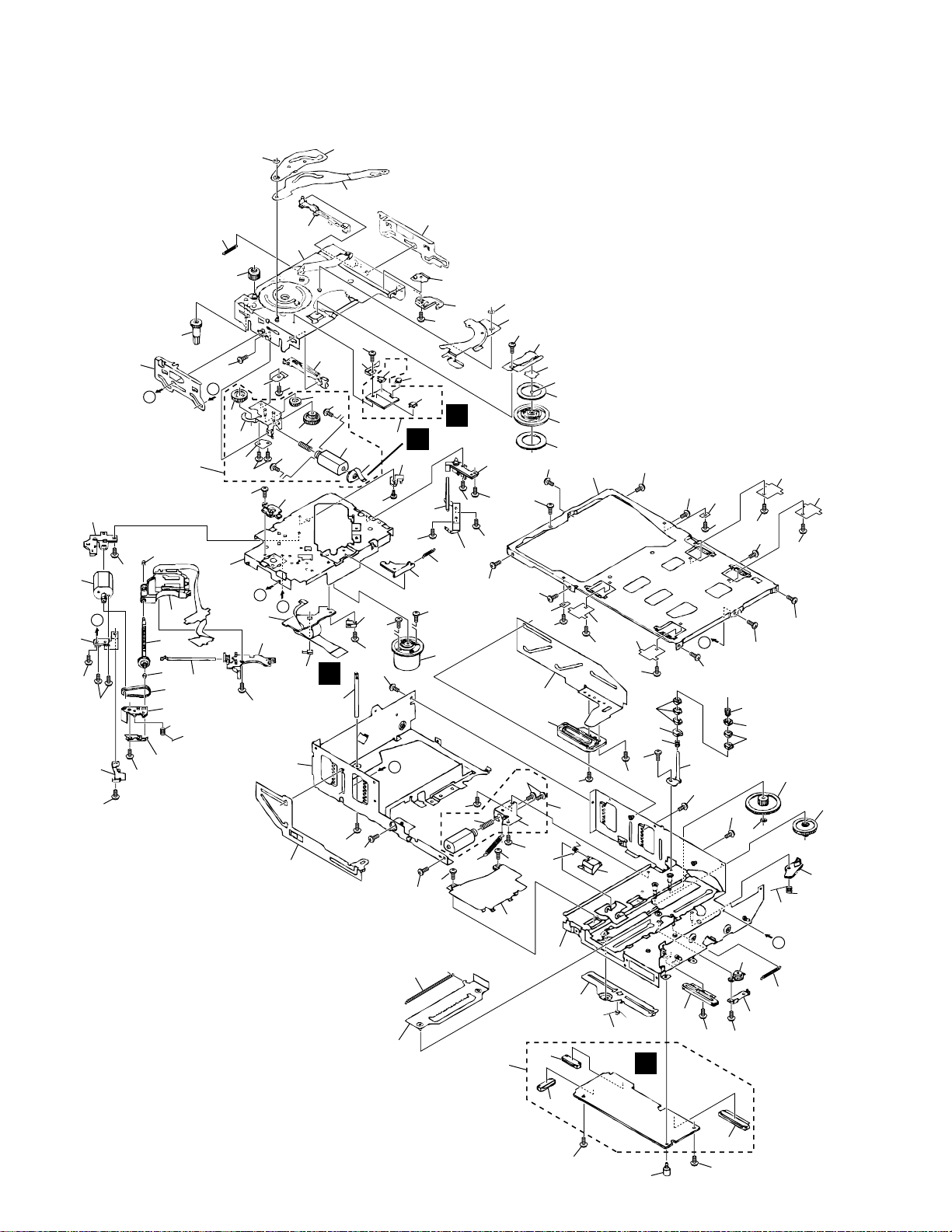
2.4 CD MECHANISM MODULE
85
A
B
A
C
C
D
D
B
13
83
27
33
67
54
13
31
24
36
97
53
37
14
6
10
6
6
6
8
52
93
50
49
46
45
44
77
74
91
95
96
73
98
28
57
89
92
90
77
68
111
15
9
62
112
113
115
114
6
6
3
64
41
47
41
42
43
90
25
48
81
72
85
77
30
110
21
71
99
60
70
26
38
84
76
11
76
61
6
6
6
6
6
6
6
6
6
6
6
6
6
6
6
6
6
90
35
90
20
12
22
63
77
102
105
104
103
40
51
87
82
106
23
65
32
66
6
6
6
6
88
59
34
56
55
58
19
18
17
39
86
29
80
75
16
79
78
5
5
1
2
7
4
69
94
59
25
25
100
109
109
108
107
107
107
101
108
107
107
109
107
109
A
B
C
D

9
CDX-M8067ZT
1 Screw CBA1426
2 CD Core Unit CWX2578
3 Pickup Unit(Service) CXX1235
4 Screw JFZ17P020FNI
5 Screw IMS26P040FMC
6 Screw(M2x2.5) CBA1037
7 Screw(M2x3) CBA1077
8 PCB Unit CWX2599
9 Holder CNV5175
10 Screw CBA1026
11 Screw CBA1166
12 Screw(M2x4) CBA1362
13 Washer CBF1002
14 Ball CNR1189
15 Guide CNV5173
16 Spring CBH2368
17 Spring CBH1827
18 Spring CBH1828
19 Spring CBH1829
20 Spring CBH1830
21 Spring CBH1919
22 Spring CBL1241
23 Spring CBL1242
24 Spring CBL1388
25 Screw(M2x3.5) CBA1114
26 Shaft CLA2803
27 Arm CNC6181
28 Lever CNC7713
29 Lever CNC6194
* 30 Bracket Unit CXB5838
31 Lever Unit CXB7200
32 Lever CNC7975
33 Lever CNC8097
34 Holder CNC7448
35 Cover CNC8129
36 Spacer CNM4879
37 Sheet CNM7576
38 PCB CNP4205
39 Spring CBL1362
40 PCB CNP4382
41 Bearing CNR1423
42 Belt CNT1053
43 Spring CBH2062
44 Gear CNV5764
45 Gear CNV4404
46 Gear CNV4406
47 Screw Unit CXB2184
48 Holder CNV4950
49 Gear CNV5305
50 Gear CNV5879
51 Rail CNV4419
52 Rail CNV4420
53 Clamper CNV6929
54 Lever CNV4422
55 Gear CNV6285
56 Gear CNV6242
57 Rack CNV4828
58 Arm CNV5868
59 Guide CNV4597
60 Arm CNV6158
61 Motor Unit(M851) CXB2187
62 Screw(M2x2.5) CBA1085
63 Motor Unit CXB1394
64 Chassis Unit CXB3530
65 Bracket Unit CXB4008
66 Chassis Unit CXB7113
67 Plate Unit CXB2262
68 Motor Unit(M853) CXB5747
69 Damper Unit CXA7714
70 Lever Unit CXA9141
71 Magazine Holder Unit CXB7201
72 Frame Unit CXB2265
73 Frame CNC9375
74 Holder CNV5176
75 Lever Unit CXB2266
76 Screw JGZ17P025FNI
77 Screw JFZ20P025FNI
78 Connector(CN701) CKS1968
79 Connector(CN801) CKS3484
80 Connector(CN101) CKS3486
81 Photo-transistor(Q851) PT4800
82 LED(D851) CN504-2
83 Arm CNC6799
84 Switch(S853) CSN1012
85 Screw(M2x2.5) CBA1041
86 Volume(VR801) CCW1021
87 Switch(S851) CSN1052
88 Guide CNV4722
89 Spring CBH1930
90 Screw(M2x3) CBA1154
91 Holder CNV5172
92 Shaft CLA3274
93 Spring CBH2091
94 Washer CBF1038
95 Bracket CBL1346
96 Spring CBH2077
97 Plate CNC6847
98 Plate CNV4402
99 Motor Unit(M852) CXB3931
100 Guide CNV5193
101 Spring CBH2070
102 Bracket CNC7425
103 Holder CNC7941
104 Spring CBL1348
105 Holder CNV5178
106 Switch(S852) CSN1051
107 Screw(M2x1.4) CBA1387
108 Spring CBL1364
109 Spring CBL1307
110 Gear CNV6240
111 Gear CNV6241
112 Screw(M2x2) CBA1250
113 Bracket Unit CXB5749
114 Spring CBL1363
115 Motor Assy(M854) CXB5882
Mark No. Description Part No. Mark No. Description Part No.
- CD MECHANISM MODULE SECTION PARTS LIST
10
A
1
234
B
C
D
12
34
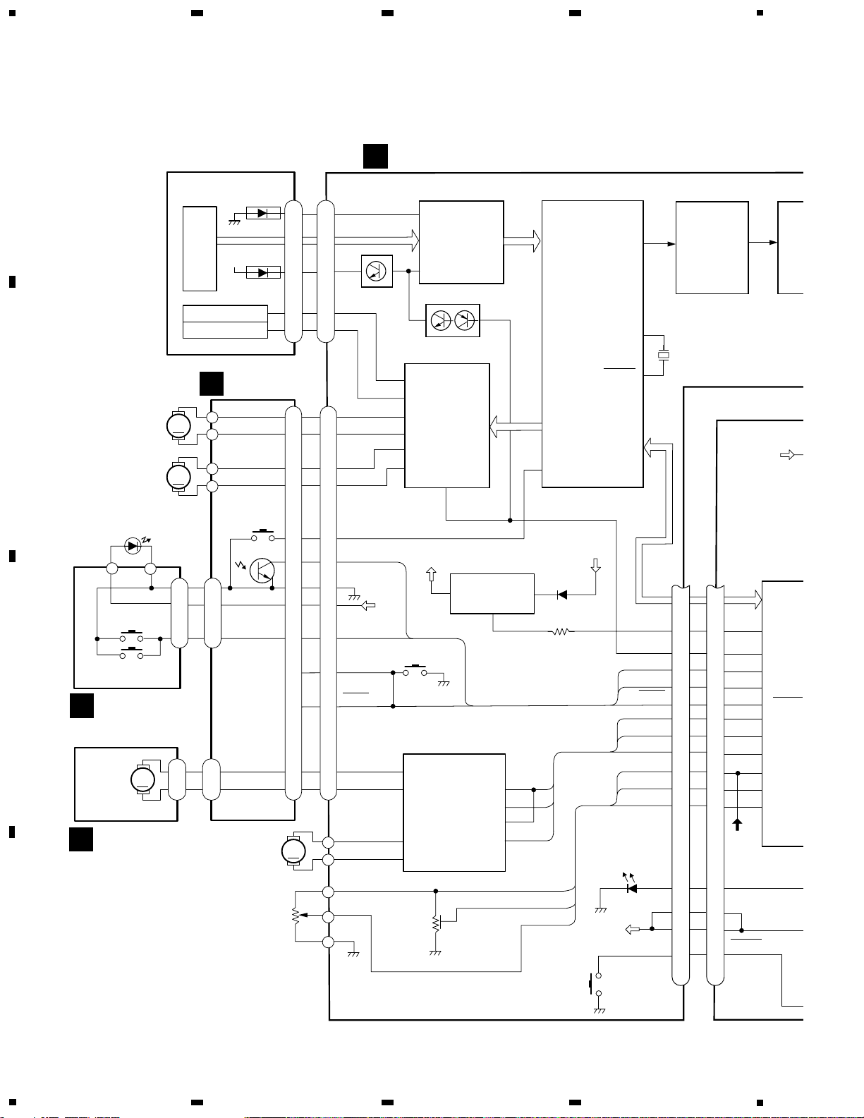
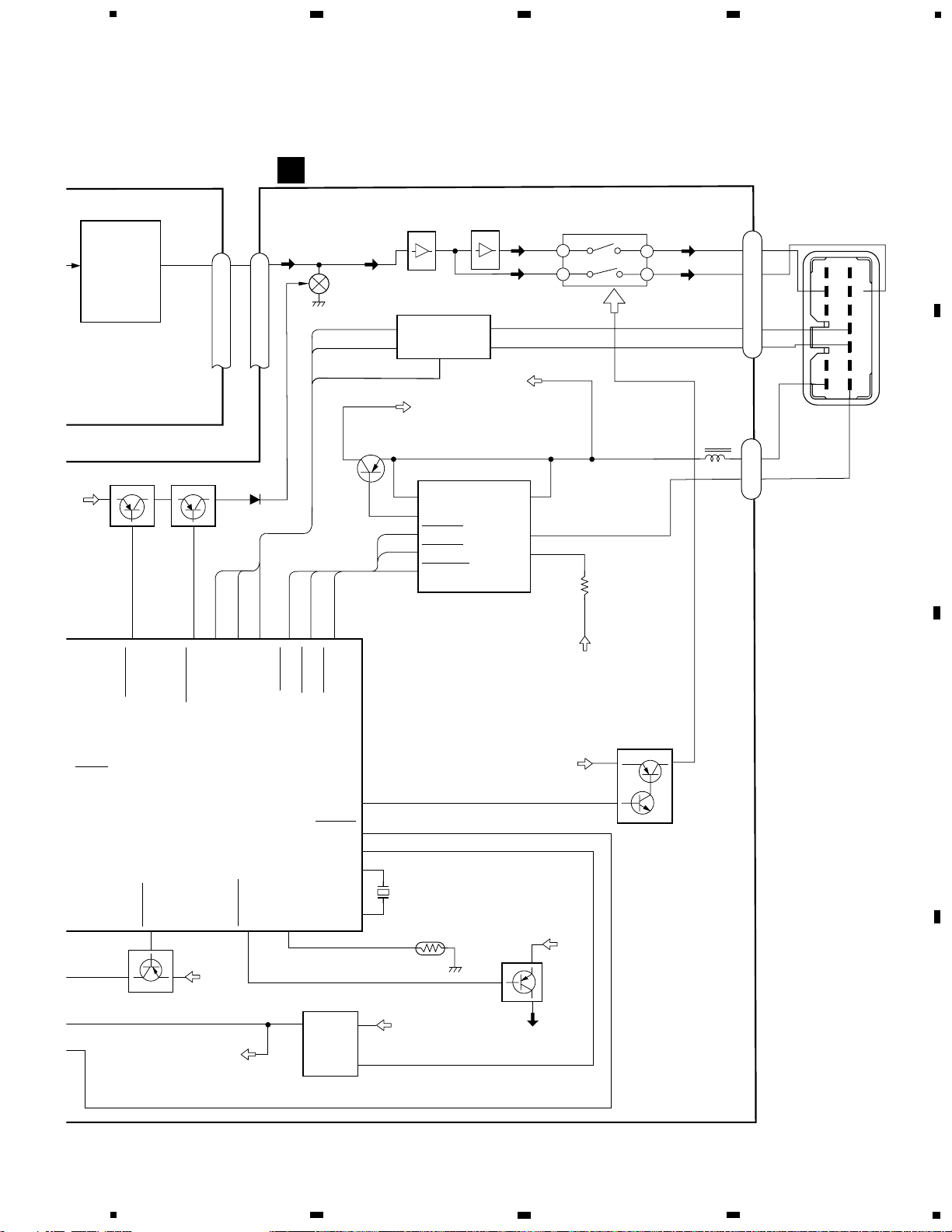
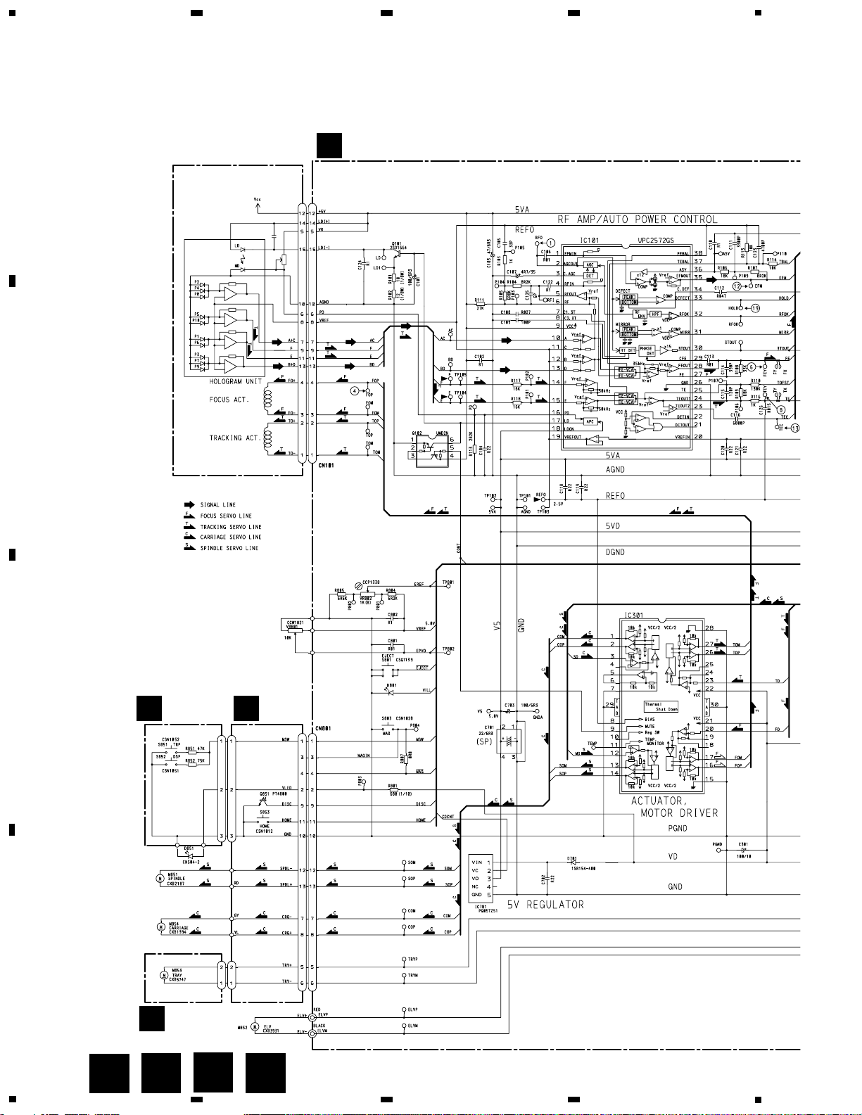
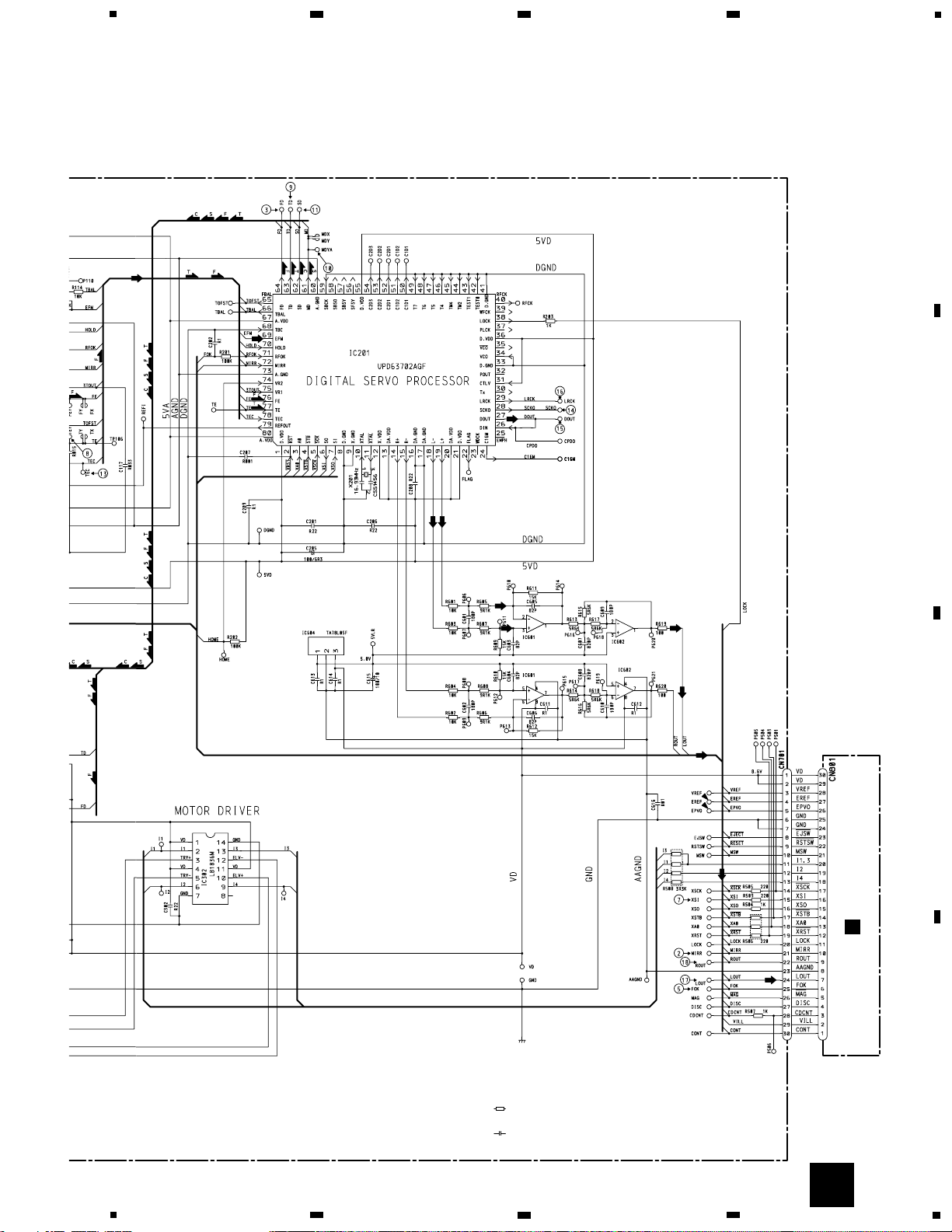
3. BLOCK DIAGRAM AND SCHEMATIC DIAGRAM
3.1 BLOCK DIAGRAM
CDX-M8067ZT
M
M
M
M
Q
VREF
77
78
72
67
66
65
23
79
76
27
55
ELVP
ELVR
VREF
I4
I2
I1/I3
MAG
MSW
DISK
CONT
CDCN
VDD
5V
EJSW
CN801
23
30
29
2
26
27
28
18
19
20
5
21
4
1
3
29
2
1
8
CN701
D801
VD
5
4
3
13
12
11
26
10
27
30
28
CDCNT
CONT
DISC
MSW
MAG
I1/I3
I2
I4
VREF
EREF
EPVO
S801
EJECT
VREF
EREF
EPVO
VR802
EREF
ELV+
ELV-
10
12
CN801
TRY+
TRY-
3
5
IC 302
LB1836M
I1
I2
I3
I4
2
6
13
9
IC
NJM
1
2
IC 601
NJM2068MD
X201
16.93MH
Z
10
11
XTAL
XTAL
L+
19
2
IC 201
UPD63702AGF
DIGITAL SERVO
PROCESSOR
RF AMP
AUTO POWER CONTROL
16
IC 101
UPC2572GS
CN101
CD CORE UNIT
17
Q102
Q101
FOP
TOP
ACTUATOR AND
MOTOR DRIVER
16
26
1
2
13
14
IC 301
BA6997FM
MUTE
9
HOME
SOP
SOM
COP
COM
DISC
PGND
VD
MSW
V5
5V
3
REGULATOR
VD
1
IC 701
PQ05DZ51
2
S803
MAG
MAG IN
MAG
MOTOR DRIVER
M852
ELV
MOTOR
VR801
EPVO
6
15
4
2
7
8
12
13
11
9
10
2
1
3
4
5
6
5
6
2
1
4
3
1
2
10
9
11
13
12
8
7
S853
HOME
Q851
3
2
1
3
2
1
2
1
M853
TRAY
MOTOR
MOTOR PCB
PCB UNIT
S851 TRP
S852 DSP
D851
M851
SPINDLE
MOTOR
M854
CARRIAGE
MOTOR
PHOTO PCB
6
4
2
MD
15
LD
+5V
FOCUS ACT
TRACKING ACT
HOLOGRAM
UNIT
PICKUP UNIT(SERVICE)
74
HOME
A
B
C
D
11
CDX-M8067ZT
5
6
7
8
5
6
7
8
A
B
C
D
BUS DRIVER
3
4
7
8
BUS-
BUS+
L+
L-
CN901
AUDIO OUTPUT
ON/OFF SWITCH
IC 803 TC74HC4066AF
UNBALANCE-BALANCE
CONVERTER
1
CD-L
Q831
MUTE
IEIN
IEOUT
2
1
5
6
IC 601
HA12187FP
IEPW
8
VDD5V
Q911
VBU14
1
2
6
5
7
OCD
CONT
ASENS
BSENS
RESET
BATT
ASENIN
BSENIN
14
9
10
IC 911 PAJ002A
ASENSE/BSENSE/RESET
VDD5V REGULATOR
VBU14
Q851
VBU14
18
22
26
28
29
X701
6.29MH
Z
TH701
Q701
VDD
5V
VREF
POWER
EJECT SW
VBU14
IC921
BA00AST
VD
VD-8.6V/6.6V REGULATOR
Q941 ILM5V
56
69
80
XOUT
XIN
POWER
EJSW
ANSW
SYSTEM
CONTROLLER
IC 701
PD5608C
TEMP
ADENA
ELVPVO
ELVREF
VREF
I4
I2
I1/I3
MAG
MSW
DISK
CONT
CDCNT
CDMUTE
IEIN
IEOUT
IEPW
ASENS
BSENS
RESET
6862 3
4
514
15 25
Q833 CD MUTE
Q852
7
CN801
CN701
4
3
2
1
2
CN902
ASENB
24
1
IC 602
NJM2068MD
2
EXTENSION UNIT
E
IC801
NJM2068V
1
2
2
3
Q702
SWVDD
EJLED
VDD5V
2
1
4
IC802
NJM2068V
IC801
NJM2068V
1
2
3
4
5
6
7
8
11
12
9
10
12
CDX-M8067ZT
A
1
234
B
C
D
12
34
BA6997FM
A
CL200FGCTU
BC
D
PICKUP UNIT(SERVICE)
CD CORE UNIT
PCB UNIT
PHOTO
PCB
MOTOR PCB
A
3.2 OVERALL CONNECTION DIAGRAM
Note: When ordering service parts, be sure to refer to “EXPLODED VIEWS AND PARTS LIST” or “ELECTRICAL
PARTS LIST”.
B
C
D
13
CDX-M8067ZT
5
6
7
8
A
B
C
D
5
6
7
8
NJM2068MD
NJM2068MD
NJM2068MD
NJM2068MD
E
Decimal points for resistor
and capacitor fixed values
are expressed as :
2.2 2R2
0.022 R022
←
←
Symbol indicates a resistor.
No differentiation is made between chip resistors and
discrete resistors.
NOTE :
Symbol indicates a capacitor.
No differentiation is made between chip capacitors and
discrete capacitors.
EXTENSION UNIT
A
14
CDX-M8067ZT
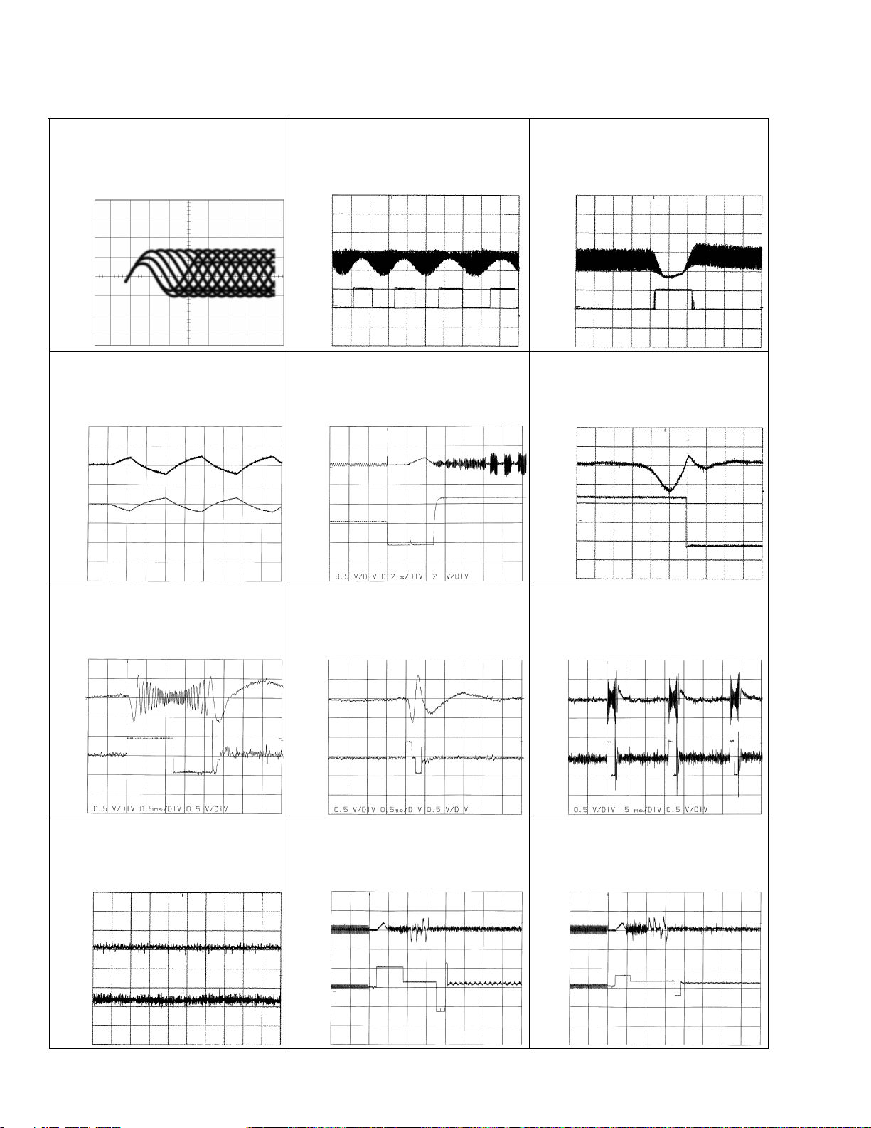
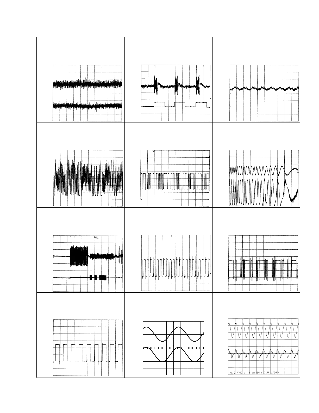
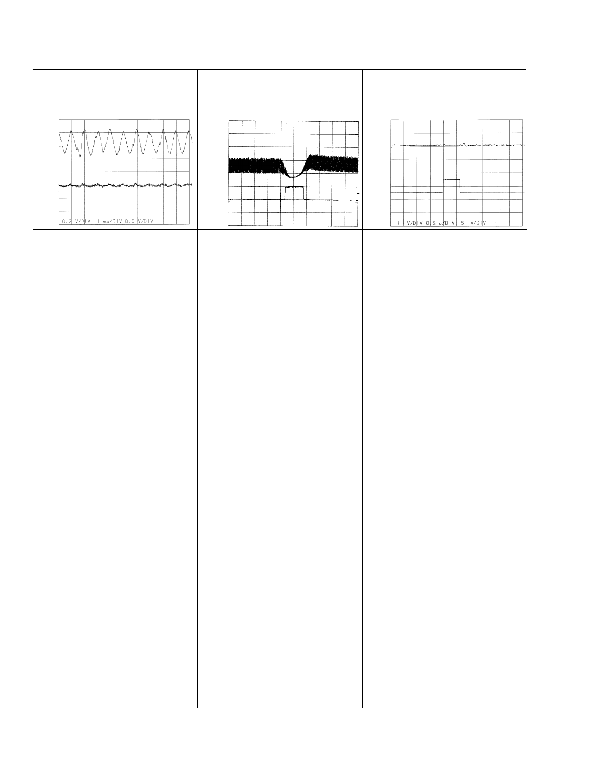
- Waveforms
1 RFO 0.5V/div. 0.5µs/div.
Normal mode: play
1 CH1: RFO 1V/div.
2 CH2: MIRR 5V/div.
Test mode: Tracking open
0.5ms/div.
1 CH1: RFO 1V/div.
2 CH2: MIRR 5V/div.
Normal mode: The defect part
passes 800µm
0.5ms/div.
3 CH1: FD 0.5V/div.
4 CH2: FOP 2V/div.
Test mode: No disc, Focus close
0.2s/div.
3 CH1: FD 0.5V/div.
5 CH2: FOK 2V/div.
Normal mode: Focus close
0.2s/div.
6 CH1: FEY 0.5V/div.
7 CH2: XSI 2V/div.
Normal mode: Focus close
1ms/div.
REFO
→
8 CH1: TEY 0.5V/div.
9 CH2: TD 0.5V/div.
Test mode: 32 tracks jump (FWD)
0.5ms/div.
8 CH1: TEY 0.5V/div.
9 CH2: TD 0.5V/div.
Test mode: Single jump (FWD)
0.5ms/div.
8 CH1: TEY 0.5V/div.
9 CH2: TD 0.5V/div.
Test mode: 100 tracks jump (FWD)
5ms/div.
6 CH1: FEY 0.1V/div.
3 CH2: FD 0.2V/div.
Normal mode: Play
20ms/div.
3 CH1: FD 0.5V/div.
0 CH2: MDYA 1V/div.
Normal mode: Focus close (12cm)
0.5s/div.
3 CH1: FD 0.5V/div.
0 CH2: MDYA 1V/div.
Normal mode: Focus close (8cm)
0.5s/div.
GND
→
GND
→
REFO
→
REFO
→
REFO
→
REFO
→
GND
→
REFO
→
REFO
→
GND
→
REFO
→
REFO
→
REFO
→
REFO
→
REFO
→
REFO
→
REFO
→
REFO
→
REFO
→
REFO
→
REFO
→
REFO
→
Note:1. The encircled numbers denote measuring pointes in the circuit diagram.
2. Reference voltage
REFO:2.5V
15
CDX-M8067ZT
8 CH1: TEY 0.2V/div.
9 CH2: TD 0.2V/div.
Normal mode: play
8 CH1: TEY 0.5V/div.
! CH2: SD 0.5V/div.
5ms/div.
0 MDYA 0.5V/div. 0.1s/div.
Normal mode: Play (12cm)
0 MDYA 0.5V/div. 10ms/div.
Long Search (12cm)
@ EFM 1V/div. 5µs/div.
Play
8 CH1: TEY 1V/div.
# CH2: TEC 1V/div.
Test mode: Focus close
Tracking open
2ms/div.
8 CH1: TEY 0.5V/div.
6 CH2: FEY 0.5V/div.
Normal mode: AGC after focus
0.2s/div.
20ms/div.
$ SCKO 2V/div. 1µs/div.
Play
% Dout 2V/div. 10µs/div.
Play
^ LRCK 2V/div. 20µs/div.
* CH1: R OUT 1V/div.
& CH2: L OUT 1V/div.
Normal mode: Play (1kHz 0dB)
6 CH1: FEY 0.2V/div.
3 CH2: FD 0.5V/div.
Normal mode: During AGC
1ms/div.
0.2ms/div.
REFO
→
REFO
→
REFO
→
REFO
→
REFO
→
REFO
→
GND
→
REFO
→
REFO
→
REFO
→
REFO
→
REFO
→
REFO
→
REFO
→
REFO
→
REFO
→
GND
→
REFO
→
GND
→
REFO
→
GND
→
REFO
→
16
CDX-M8067ZT
8 CH1: TEY 0.2V/div.
9 CH2: TD 0.5V/div.
Normal mode: During AGC
1 CH1: RFO 1V/div.
^ CH2: HOLD 5V/div.
Normal mode: The defect part passes
800µm
1ms/div.
0.5ms/div.
3 CH1: FD 1V/div.
^ CH2: HOLD 5V/div.
Normal mode: The defect part passes
800µm
0.5ms/div.
GND
→
GND
→
REFO
→
REFO
→
REFO
→

17
CDX-M8067ZT
 Loading...