

Pioneer CDS-9036 Service Manual
CAR COMPACT DISC PLAYER
CDS-9036ZT ES
Se
r
vic
e
M
a
nu
a
l
TOYOTA
PIONEER ELECTRONIC CORPORATION 4-1, Meguro 1-Chome, Meguro-ku, Tokyo 153-8654, Japan
PIONEER ELECTRONICS SERVICE INC. P.O.Box 1760, Long Beach, CA 90801-1760 U.S.A.
PIONEER ELECTRONIC [EUROPE] N.V. Haven 1087 Keetberglaan 1, 9120 Melsele, Belgium
PIONEER ELECTRONICS ASIACENTRE PTE.LTD. 501 Orchard Road, #10-00, Wheelock Place, Singapore 238880
C PIONEER ELECTRONIC CORPORATION 1998
ORDER NO.
CRT2262
K-ZZS. SEPT. 1998 Printed in Japan
VEHICLE DESTINATION PRODUCED AFTER TOYOTA PART No. ID No. PIONEER MODEL No.
Not specified THAILAND August 1998 08601-00894 CDS-9036ZT/ES
- The CDS-9036ZT/ES is a genuine model of option from TOYOTA MOTOR CORPORATION.
- The CDS-9036ZT/ES uses AVC-LAN for bus.
- See the separate manual CX-597(CRT1829) for the CD mechanism description, disassembly and circuit
description.
- The CD mechanism employed in this model is one of S7 series.
CONTENTS
1. SAFETY INFORMATION ............................................2
2. EXPLODED VIEWS AND PARTS LIST.......................3
3. SCHEMATIC DIAGRAM .............................................8
4. PCB CONNECTION DIAGRAM ................................20
5. ELECTRICAL PARTS LIST ........................................26
6. ADJUSTMENT..........................................................29
7. GENERAL INFORMATION .......................................33
7.1 IC ........................................................................33
7.2 DIAGNOSIS ........................................................35
7.2.1 SELF-DIAGNOSTIC FUNCTION...............35
7.2.2 DISASSEMBLY .........................................39
7.2.3 TEST MODE..............................................40
7.2.4 CONNECTOR FUNCTION DESCRIPTION.......42
7.3 BLOCK DIAGRAM ..............................................43
8. OPERATIONS AND SPECIFICATIONS.....................44

2
CDS-9036ZT
1. SAFETY INFORMATION
This service manual is intended for qualified service technicians; it is not meant for the casual do-it-yourselfer.
Qualified technicians have the necessary test equipment and tools, and have been trained to properly and safely repair
complex products such as those covered by this manual.
Improperly performed repairs can adversely affect the safety and reliability of the product and may void the warranty.
If you are not qualified to perform the repair of this product properly and safely; you should not risk trying to do so
and refer the repair to a qualified service technician.
- CD Player Service Precautions
1. For pickup unit(CXX1231) handling, please refer
to"Disassembly"(CX-597 Service Manual CRT1829).
During replacement, handling precautions shall be
taken to prevent an electrostatic discharge(protection
by a short pin).
2. During disassembly, be sure to turn the power off
since an internal IC might be destroyed when a connector is plugged or unplugged.
3. Please checking the grating after changing the service pickup unit(see page 31).
3
CDS-9036ZT
7
5
3
2
6
10
9
4
8
1
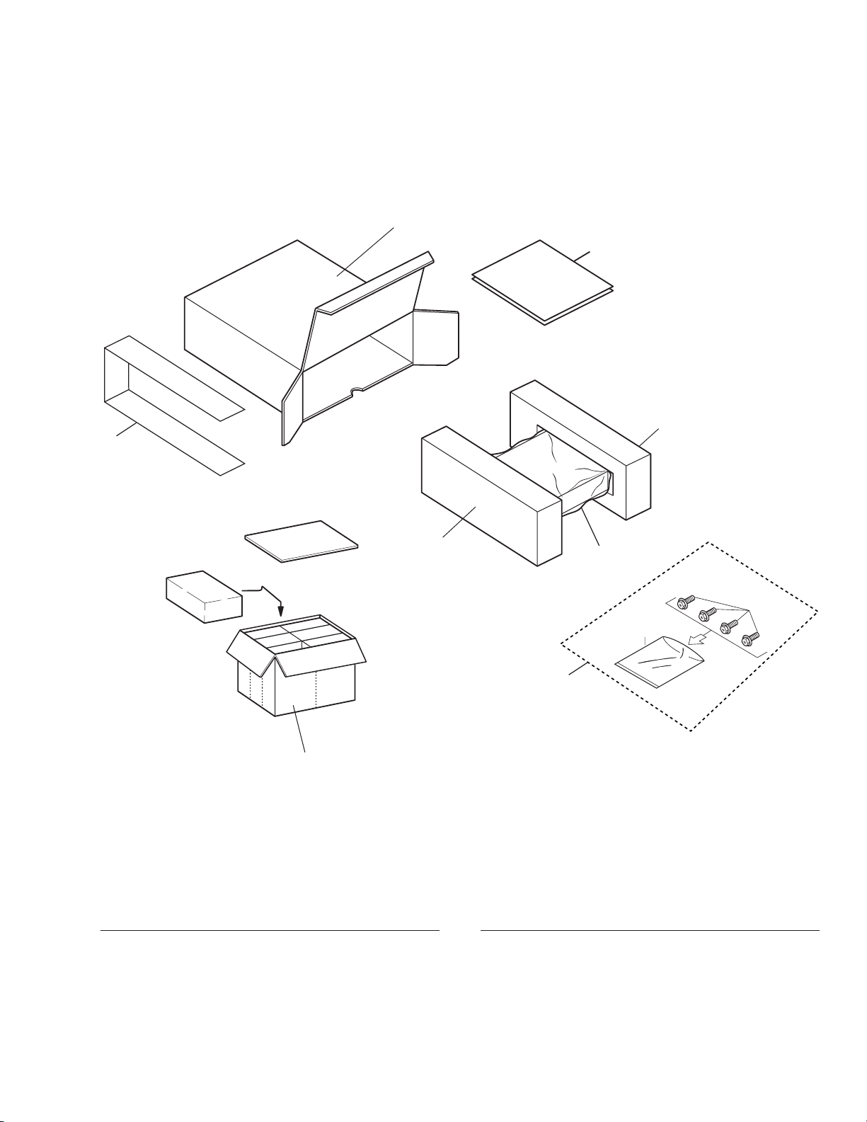
2. EXPLODED VIEWS AND PARTS LIST
2.1 PACKING
NOTE:
- Parts marked by "*"are generally unavailable because they are not in our Master Spare Parts List.
- Screws adjacent to
∇ mark on the product are used for disassembly.
- PACKING SECTION PARTS LIST
Mark No. Description Part No.
Mark No. Description Part No.
1 Screw Assy CEA1854
2 Protector CHP1944
3 Protector CHP1945
* 4 Sheet CHW1645
5 Owner’s Manual CRD2796
(English,Thai)
* 6 Polyethylene Bag E36-609
7 Carton CHA2424
8 Contain Box CHL3594
* 9 Polyethylene Bag CEG-127
10 Screw HMF50P080FMC
4
CDS-9036ZT
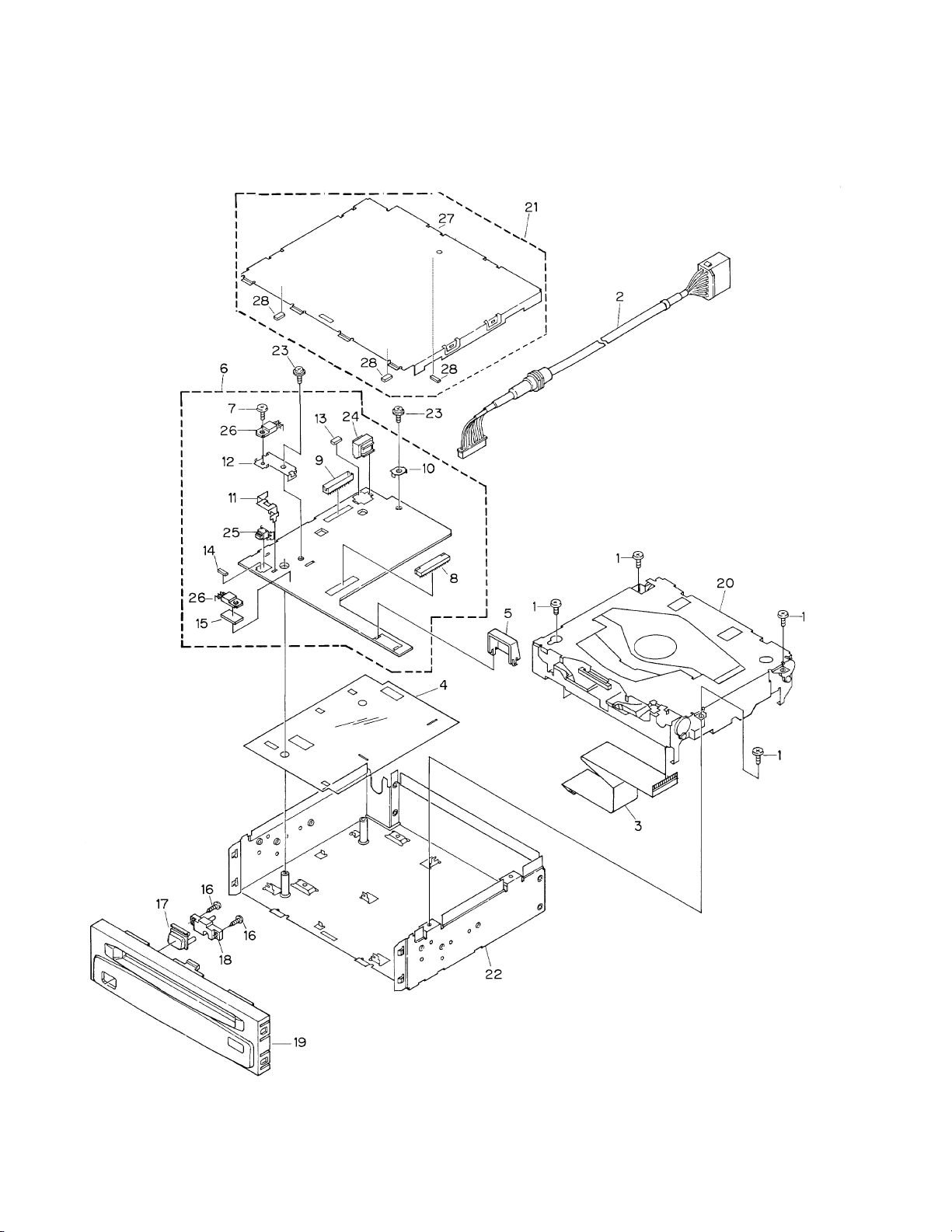
2.2 EXTERIOR

5
CDS-9036ZT
1 Screw BMZ26P050FMC
2 Cord Assy CDE5259
3 Connector CDE5447
4 Insulator CNM5365
5 Holder CNV5014
6 Control Unit CWM5461
7 Screw BMZ26P050FMC
8 Connector(CN601) CKS2228
9 Plug(CN901) CKS2721
10 Holder CNC2218
11 Holder CNC6071
12 Holder CNC7188
13 Spacer CNM2683
14 Spacer CNM4676
15 Spacer CNM5523
16 Screw BPZ20P080FMC
17 Button(Eject) CAC5244
18 Lighting Conductor CNV5013
19 Grille Unit CXB1803
20 CD Mechanism Module CXK5020
21 Case Unit CXB2146
22 Chassis Unit CXB1552
23 Screw IMS30P050FMC
24 Choke Coil(L901) CTH1129
25 Push Switch(S601) CSG1065
26 Transistor(Q704, 911) 2SB1185
27 Case CNB2203
28 Cushion CNM5473
- EXTERIOR SECTION PARTS LIST
Mark No. Description Part No.
6
CDS-9036ZT
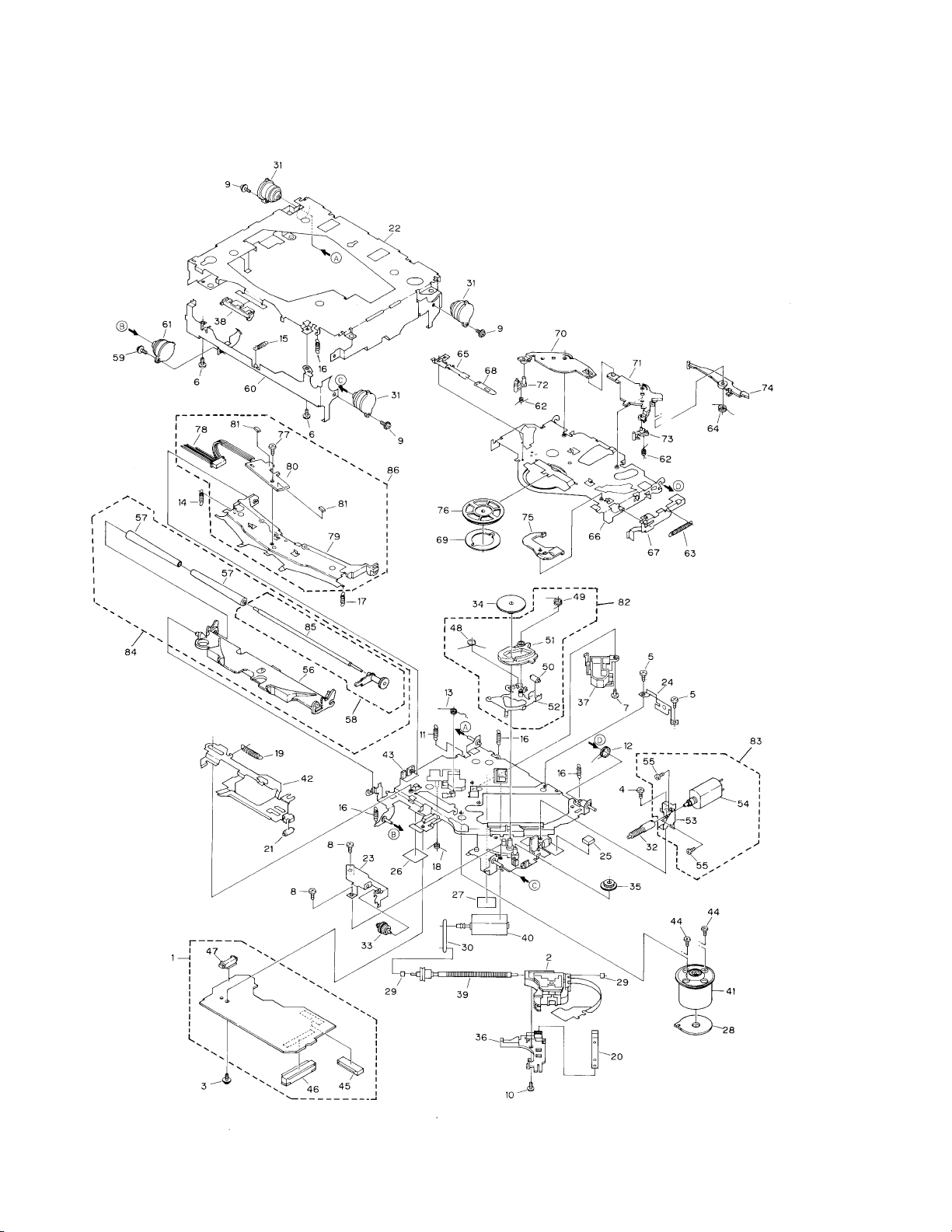
2.4 CD MECHANISM MODULE

1 Control Unit(S7) CWX2332
2 Pickup Unit(Service) CXX1231
3 Screw IMS26P035FMC
4 Screw BMZ20P025FMC
5 Screw BMZ20P040FMC
6 Screw BSZ20P040FMC
7 Screw(M2×3) CBA1077
8 Screw(M2×2) CBA1250
9 Screw(M2×5) CBA1296
10 Screw(M2×3.85) CBA1362
11 Spring CBH1724
12 Spring CBH1729
13 Spring CBH1730
14 Spring CBH1731
15 Spring CBH1732
16 Spring CBH1745
17 Spring CBH1848
18 Spring CBH1849
19 Spring CBH1939
20 Spring CBL1214
21 Roller CLA2627
22 Frame CNC5796
23 Bracket CNC5871
* 24 Bracket CNC6376
25 Cushion CNM3917
26 Sheet CNM4873
* 27 Sheet CNM5116
28 PCB CNP4230
29 Bearing CNR1415
30 Belt CNT1071
31 Damper CNV3974
32 Gear CNV4128
33 Gear CNV4129
34 Gear CNV4857
35 Gear CNV4131
36 Holder CNV4663
37 Holder CNV5071
38 Guide CNV4484
39 Screw Unit CXA8699
40 CRG Motor Unit(M2) CXB3043
41 Motor Unit(M1) CXA8912
42 Lever Unit CXA9300
43 Chassis Unit CXB2574
44 Screw JFZ20P025FMC
45 Connector(CN101) CKS1953
46 Connector(CN701) CKS2774
47 Connector(CN801) CKS2196
48 Spring CBH1832
49 Spring CBH1833
50 Roller CLA2627
51 Arm CNV4136
52 Arm Unit CXA8565
53 Bracket CNC6056
54 Load Motor Unit(M3) CXA8702
55 Screw JFZ20P025FMC
56 Arm CNV4120
57 Roller CNV4509
58 Gear Unit CXA8701
59 Screw(M2×5) CBA1455
60 Frame CNC5797
61 Damper CNV3974
62 Spring CBH1736
63 Spring CBH1863
64 Spring CBH1945
65 Spring CBL1269
66 Arm CNC5799
67 Lever CNC6054
68 Spacer CNM3315
69 Sheet CNM4849
70 Arm CNV5436
71 Arm CNV4123
72 Arm CNV4124
73 Arm CNV4125
74 Arm CNV4138
75 Arm CNV4139
76 Clamper CNV4140
77 Screw(M2×2) CBA1250
78 Connector CDE4576
79 Arm CNC7383
* 80 Gathering PCB CNX2533
81 Photo-transistor(Q1, 2) CPT-230S-X
82 ELBO Arm Assy CXA8889
83 Load Motor Assy CXA8891
84 LO Arm Assy CXA8892
85 Shaft CLA3133
86 Guide Arm Assy CXB1851
7
CDS-9036ZT
- CD MECHANISM MODULE SECTION PARTS LIST
Mark No. Description Part No. Mark No. Description Part No.
8
CDS-9036ZT
1
23
4
1234
D
C
B
A
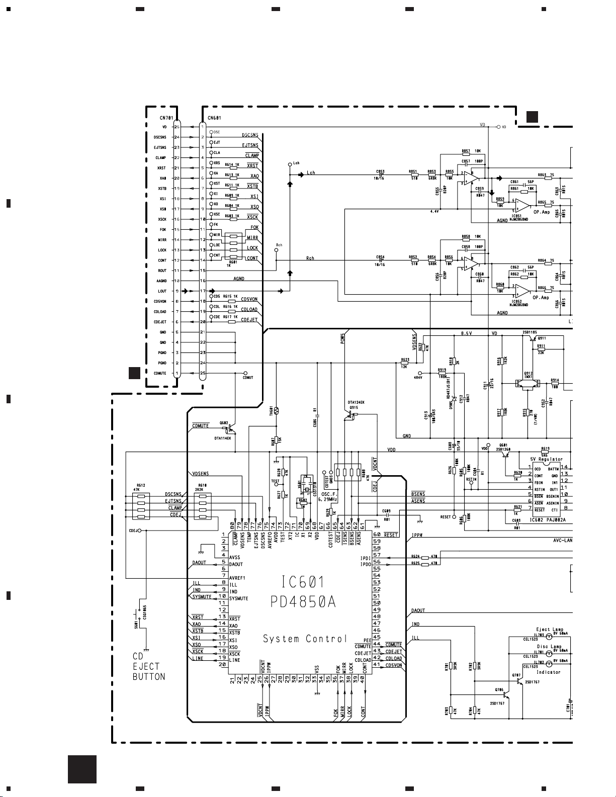
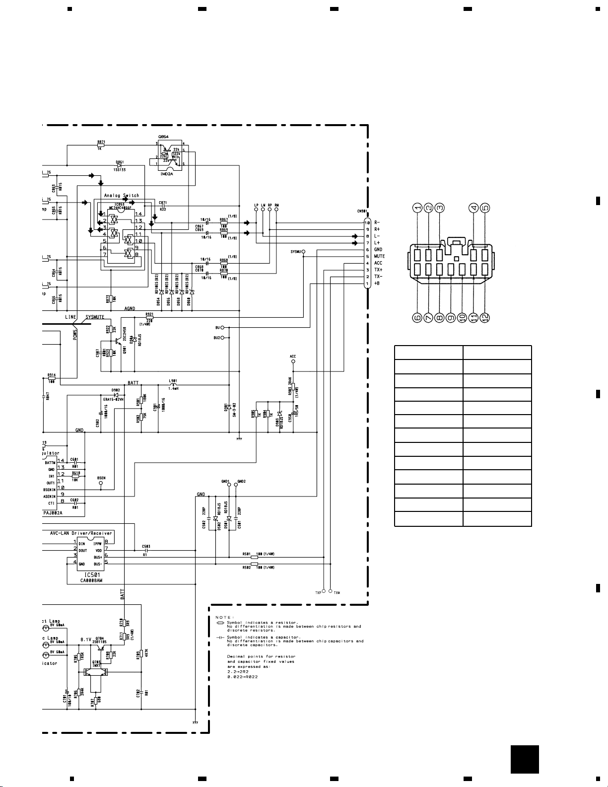
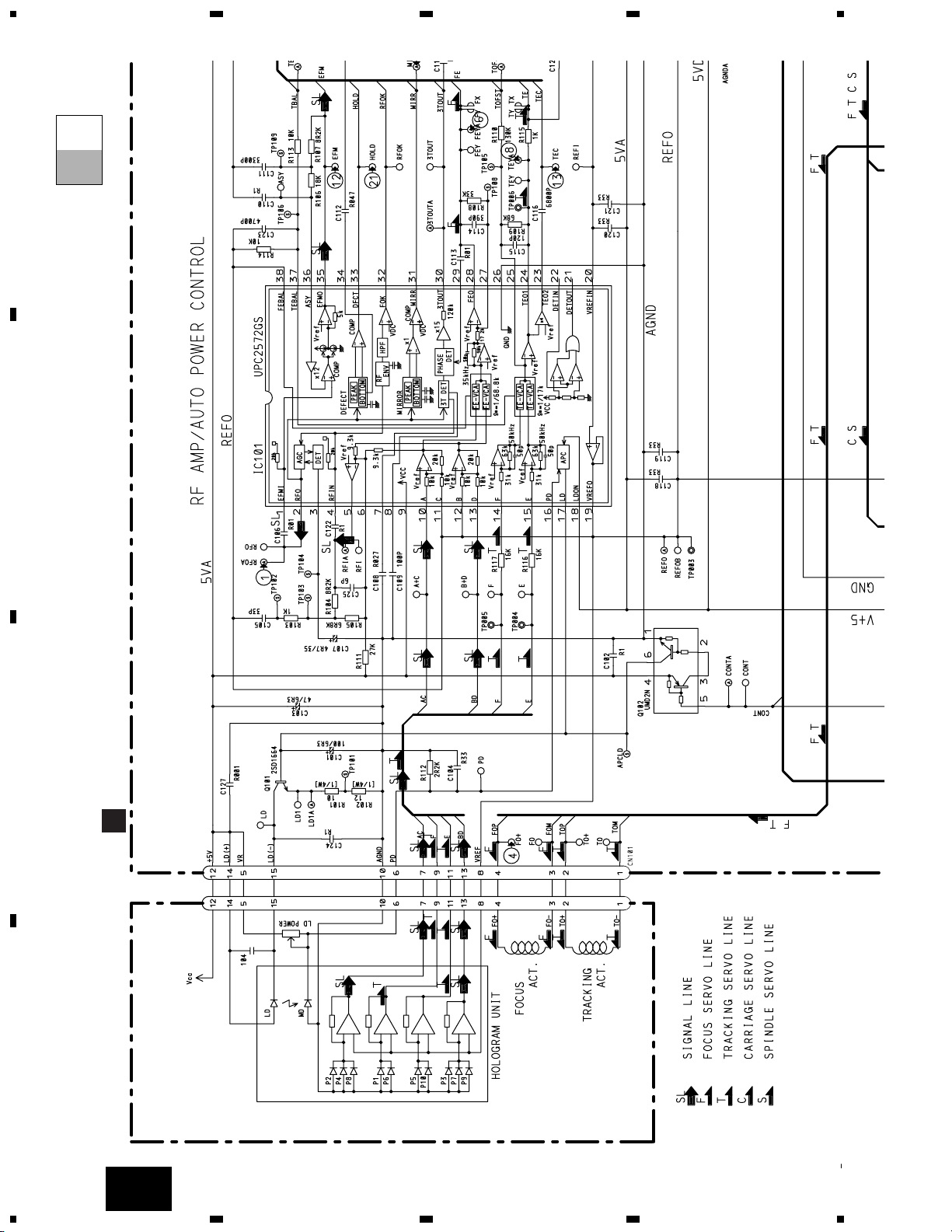
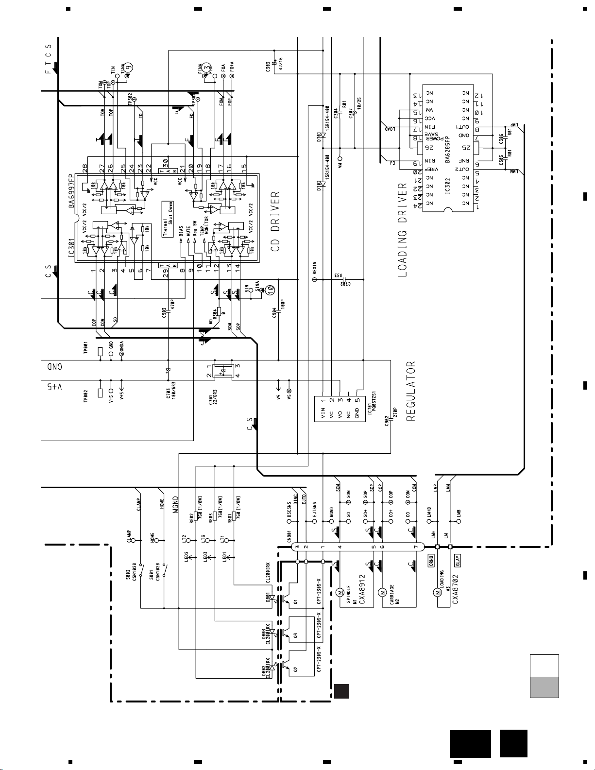
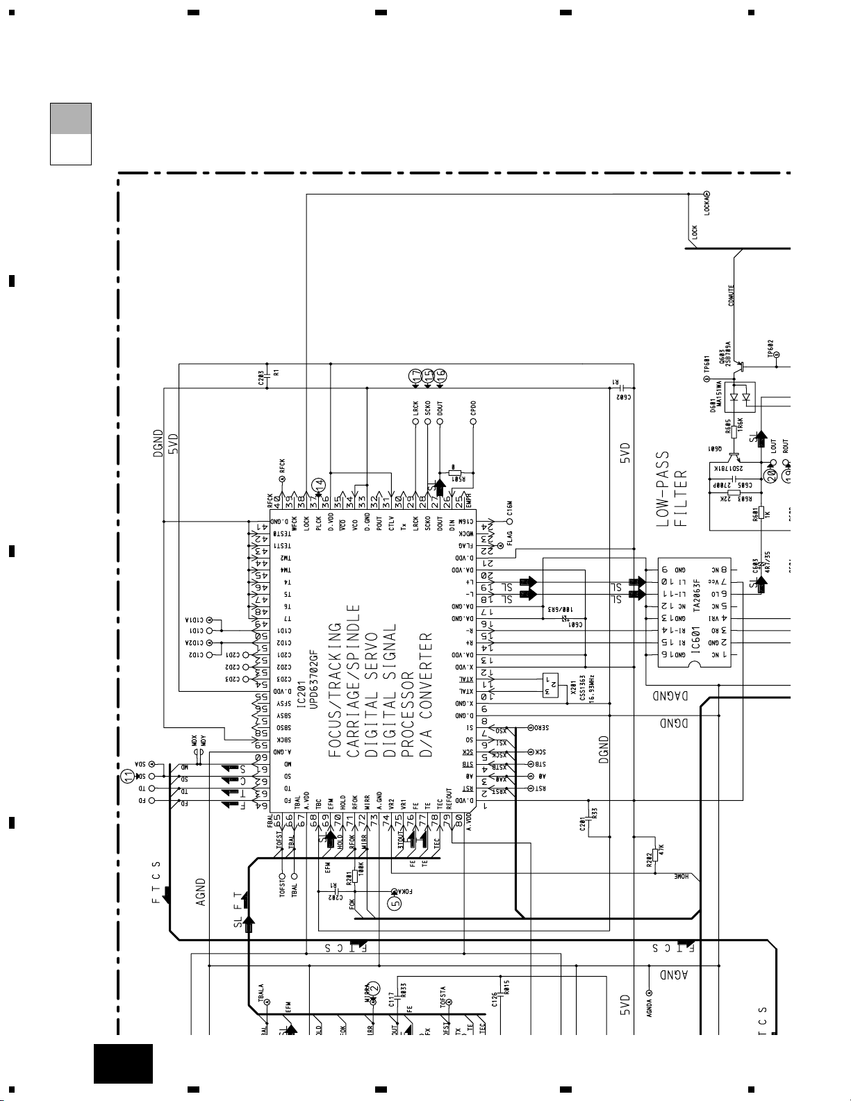
3. SCHEMATIC DIAGRAM
3.1 OVERALL CONNECTION DIAGRAM
Note: When ordering service parts, be sure to refer to “EXPLODED VIEWS AND PARTS LIST” or “ELECTRICAL PARTS
LIST”.
CONTR
A
CONTROL UNIT(S7)
B
A
9
CDS-9036ZT
5
6
78
5
6
78
D
C
B
A
A
Connector No Description
1R+
2L+
3 SGND
4 MUTE
5+B
6R≠
7L≠
8 GND
9TX≠
10 TX+
11 NC
12 ACC
10
CDS-9036ZT
1
23
4
1234
D
C
B
A
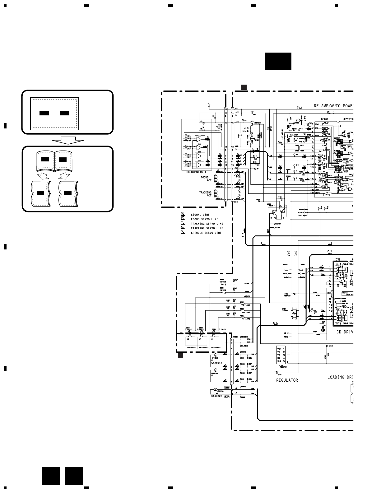
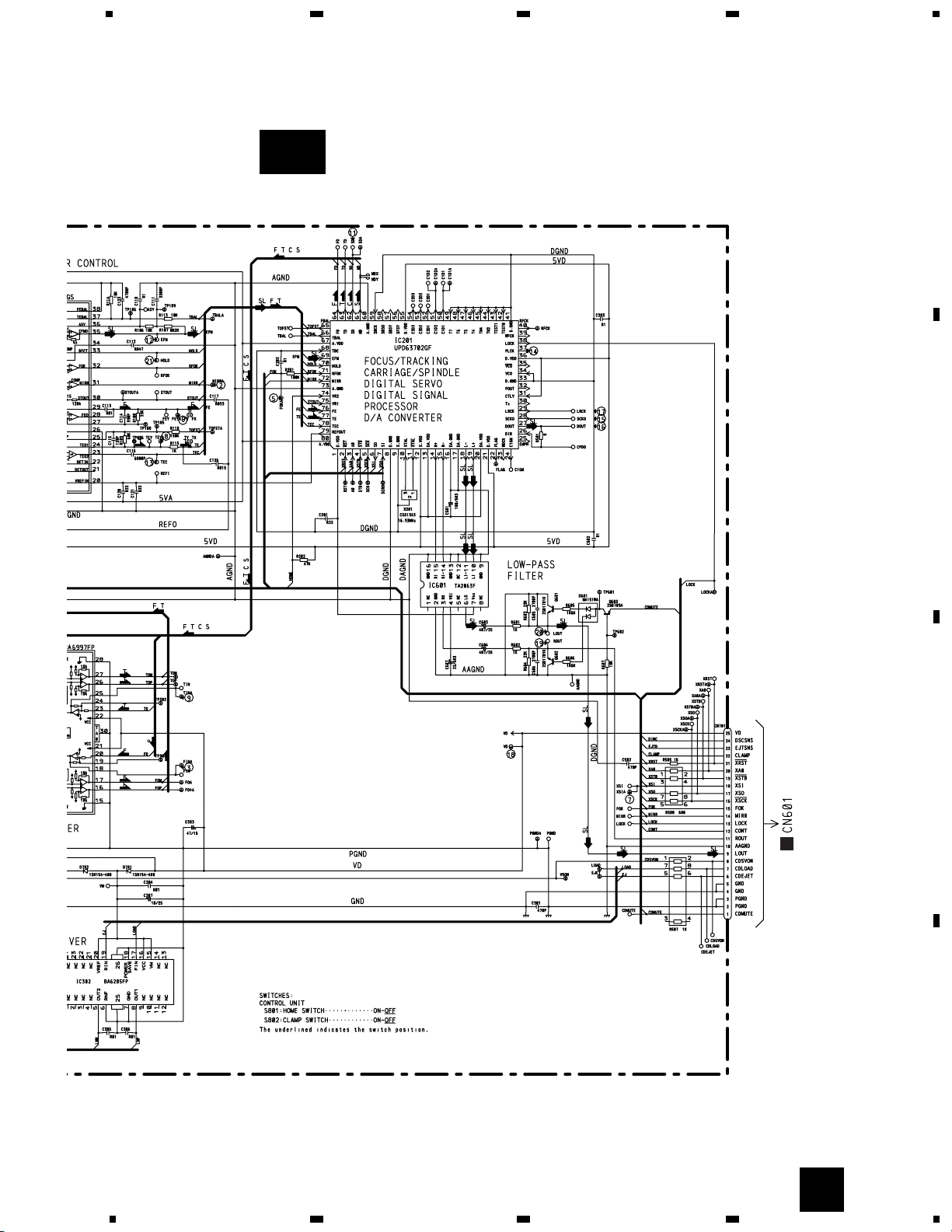
3.2 CD MECHANISM MODULE(GUIDE PAGE)
CONTROL UNIT(S7)
B
PICKUP UNIT(SERVICE)
C
PHOTO UNIT
CXB3043
A-a A-b
A-aA-a
A-b A-b
A-b A-b
A-a A-a
Large size
SCH diagram
Guide page
Detailed page
CB
B-a
11
CDS-9036ZT
5
6
78
5
6
78
D
C
B
A
A
B
B-b
12
CDS-9036ZT
1
23
4
234
D
C
B
A
1
B-a
B-a
B-b
CONTROL UNIT(S7)
B
PICKUP UNIT(SERVICE)
13
CDS-9036ZT
5
6
78
5
6
7
D
C
B
A
8
B-a
C
B-a
B-b
C
PHOTO UNIT
CXB3043
14
CDS-9036ZT
1
23
4
234
D
C
B
A
1
B-b
B-a
B-b
 Loading...