

Page 1
PIONEER ELECTRONIC CORPORATION 4-1, Meguro 1-Chome, Meguro-ku, Tokyo 153-8654, Japan
PIONEER ELECTRONICS SERVICE INC. P.O.Box 1760, Long Beach, CA 90801-1760 U.S.A.
PIONEER ELECTRONIC [EUROPE] N.V. Haven 1087 Keetberglaan 1, 9120 Melsele, Belgium
PIONEER ELECTRONICS ASIACENTRE PTE.LTD. 253 Alexandra Road, #04-01, Singapore 159936
C PIONEER ELECTRONIC CORPORATION 1999
K-ZZU. APR. 1999 Printed in Japan
ORDER NO.
CRT2381
1DIN SINGLE CD PLAYER
CDS-1096ZT ES
TOYOTA
- This additional service manual is designed to be used together with Model CDS-9036ZT/ES Service
Manual CRT2262. Refer to it for finding parts numbers and adjustment,etc. which are not shown in
this manual.
VEHICLE DESTINATION PRODUCED AFTER PART No. ID No. PIONEER MODEL No.
CAMRY MIDDLE EAST APR. 1999 86270-06010 CDS-1096ZT/ES
Page 2

CDS-1096ZT
EXPLODED VIEWS AND PARTS LIST
PACKING (Page 3)
- PACKING SECTION PARTS LIST
Part No.
Mark No. Description CDS-9036ZT/ES CDS-1096ZT/ES
5 Owner's Manual CRD2796 •••••
8 Contain Box CHL3594 CHL3814
Connector Assy ••••• CXB1856
EXTERIOR (Page 4)
- EXTERIOR SECTION PARTS LIST *: Non Spare Part
Part No.
Mark No. Description CDS-9036ZT/ES CDS-1096ZT/ES
2 Cord Assy CDE5259 CDE5402
6 Control Unit CWM5461 CWM6586
ELECTRICAL PARTS LIST(Page 26)
Control Unit
Part No.
Symbol and Description CDS-9036ZT/ES CDS-1096ZT/ES
IC601 IC PD4850A PD4809B
IL701-703 Lamp 8V 60mA CEL1523 CEL1623
Page 3
PIONEER CORPORATION 4-1, Meguro 1-Chome, Meguro-ku, Tokyo 153-8654, Japan
PIONEER ELECTRONICS SERVICE INC. P.O.Box 1760, Long Beach, CA 90801-1760 U.S.A.
PIONEER EUROPE N.V. Haven 1087 Keetberglaan 1, 9120 Melsele, Belgium
PIONEER ELECTRONICS ASIACENTRE PTE.LTD. 253 Alexandra Road, #04-01, Singapore 159936
C PIONEER CORPORATION 2001
K-ZZS. MAR. 2001 Printed in Japan
ORDER NO.
CRT2676
1DIN SINGLE CD PLAYER
CDS-1096ZT X1N/ES
TOYOTA
- This service manual should be used together with the manual(s) listed below.
For the parts numbers, adjustments, etc. which are not shown in this manual,
refer to the following manual(s).
Model No. Order No. Mech. Module Remarks
CDS-9036ZT/ES CRT2262
CX-597 CRT1829 S7 CD Mech. Module:Circuit Description, Mech.Description, Disassembly
VEHICLE DESTINATION PRODUCED AFTER TOYOTA PART No. ID No. PIONEER MODEL No.
CAMRY MIDDLE EAST August 2001 86270-06010 CDS-1096ZT/X1N/ES
EXPLODED VIEWS AND PARTS LIST
PACKING(Page 3)
- PACKING SECTION PARTS LIST * : Non spare part
Part No.
Mark No. Symbol and Description CDS-9036ZT/ES CDS-1096ZT/X1N/ES
1 Screw Assy CEA1854 Not used
* 4 Sheet CHW1645 CHW1892
5 Owner’s Manual CRD2796 Not used
6 Polyethylene Bag * E36-609 CEG1297
7 Carton CHA2424 CHG4349
8 Contain Box CHL3594 CHL4349
* 9 Polyethylene Bag CEG-127 Not used
10 Screw HMF50P080FMC Not used
Page 4
CDS-1096ZT
CD MECHANISM MODULE(Page 6)
- CD MECHANISM MODULE SECTION PARTS LIST
Part No.
Mark No. Symbol and Description CDS-9036ZT/ES CDS-1096ZT/X1N/ES
69 Sheet CNM4849 CNM6412
70 Arm CNV5436 CNV5031
75 Arm CNV4139 CNV5032
76 Clamper CNV5308 CNV5912
ELECTRICAL PARTS LIST(Page 26)
- CONTROL UNIT
Part No.
Symbol and Description CDS-9036ZT/ES CDS-1096ZT/X1N/ES
IC 501 HA12187FP CA0008AM
IC 601 PD4850A PD4809B
IL 701 CEL1523 CEL1623
IL 702 CEL1523 CEL1623
IL 703 CEL1523 CEL1623
R 904 RN1/10SE1001D RS1/10S102J
EXTERIOR(Page 4)
- EXTERIOR SECTION PARTS LIST
Part No.
Mark No. Symbol and Description CDS-9036ZT/ES CDS-1096ZT/X1N/ES
2 Cord Assy CDE5259 CDE5402
3 Connector CDE5447 CDE6667
4 Insulator CNM5365 CNM7321
6 Control Unit CWM5461 CWM6586
13 Spacer CNM2683 CNM7319
14 Spacer CNM4676 CNM7320
15 Spacer CNM5523 CNM7322
20
CD Mechanism Module(S7) CXK5020 CXK5060
Insulator CNM6305 CNM7323
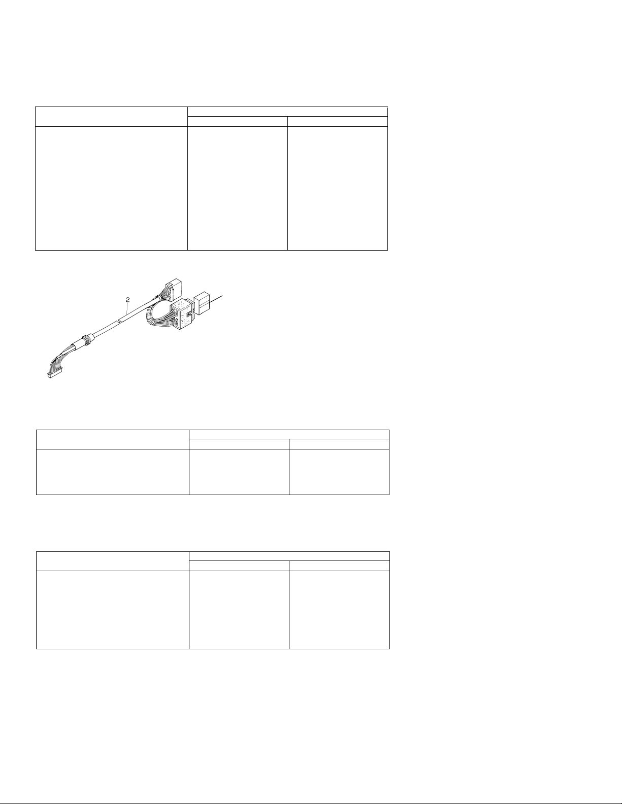
Connector Assy Not used CXB1856
Connector Assy
CXB1856
Page 5
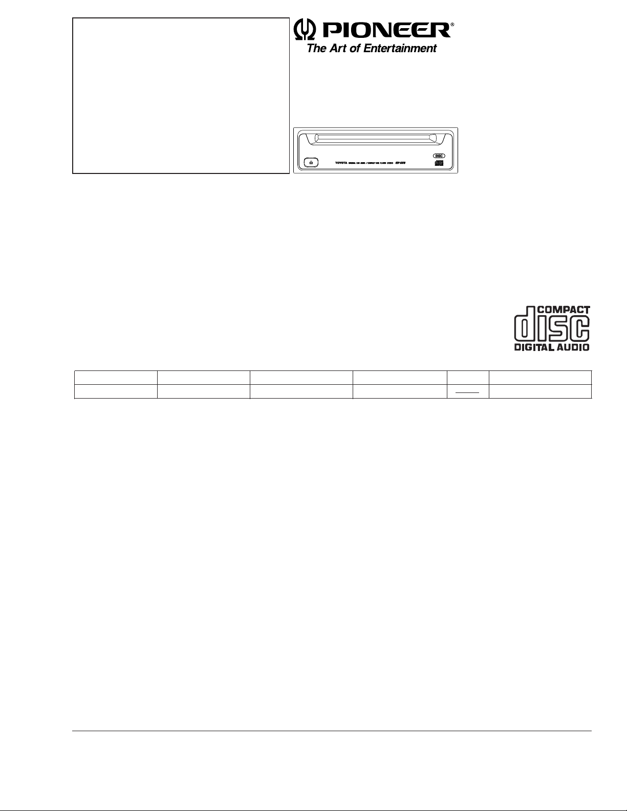
CAR COMPACT DISC PLAYER
CDS-9036ZT ES
Se
r
vic
e
M
a
nu
a
l
TOYOTA
PIONEER ELECTRONIC CORPORATION 4-1, Meguro 1-Chome, Meguro-ku, Tokyo 153-8654, Japan
PIONEER ELECTRONICS SERVICE INC. P.O.Box 1760, Long Beach, CA 90801-1760 U.S.A.
PIONEER ELECTRONIC [EUROPE] N.V. Haven 1087 Keetberglaan 1, 9120 Melsele, Belgium
PIONEER ELECTRONICS ASIACENTRE PTE.LTD. 501 Orchard Road, #10-00, Wheelock Place, Singapore 238880
C PIONEER ELECTRONIC CORPORATION 1998
ORDER NO.
CRT2262
K-ZZS. SEPT. 1998 Printed in Japan
VEHICLE DESTINATION PRODUCED AFTER TOYOTA PART No. ID No. PIONEER MODEL No.
Not specified THAILAND August 1998 08601-00894 CDS-9036ZT/ES
- The CDS-9036ZT/ES is a genuine model of option from TOYOTA MOTOR CORPORATION.
- The CDS-9036ZT/ES uses AVC-LAN for bus.
- See the separate manual CX-597(CRT1829) for the CD mechanism description, disassembly and circuit
description.
- The CD mechanism employed in this model is one of S7 series.
CONTENTS
1. SAFETY INFORMATION ............................................2
2. EXPLODED VIEWS AND PARTS LIST.......................3
3. SCHEMATIC DIAGRAM .............................................8
4. PCB CONNECTION DIAGRAM ................................20
5. ELECTRICAL PARTS LIST ........................................26
6. ADJUSTMENT..........................................................29
7. GENERAL INFORMATION .......................................33
7.1 IC ........................................................................33
7.2 DIAGNOSIS ........................................................35
7.2.1 SELF-DIAGNOSTIC FUNCTION...............35
7.2.2 DISASSEMBLY .........................................39
7.2.3 TEST MODE..............................................40
7.2.4 CONNECTOR FUNCTION DESCRIPTION.......42
7.3 BLOCK DIAGRAM ..............................................43
8. OPERATIONS AND SPECIFICATIONS.....................44
Page 6

2
CDS-9036ZT
1. SAFETY INFORMATION
This service manual is intended for qualified service technicians; it is not meant for the casual do-it-yourselfer.
Qualified technicians have the necessary test equipment and tools, and have been trained to properly and safely repair
complex products such as those covered by this manual.
Improperly performed repairs can adversely affect the safety and reliability of the product and may void the warranty.
If you are not qualified to perform the repair of this product properly and safely; you should not risk trying to do so
and refer the repair to a qualified service technician.
- CD Player Service Precautions
1. For pickup unit(CXX1231) handling, please refer
to"Disassembly"(CX-597 Service Manual CRT1829).
During replacement, handling precautions shall be
taken to prevent an electrostatic discharge(protection
by a short pin).
2. During disassembly, be sure to turn the power off
since an internal IC might be destroyed when a connector is plugged or unplugged.
3. Please checking the grating after changing the service pickup unit(see page 31).
Page 7
3
CDS-9036ZT
7
5
3
2
6
10
9
4
8
1
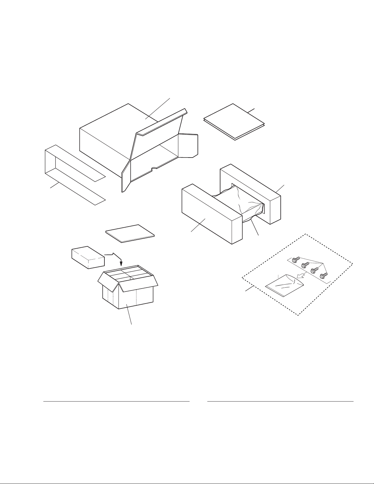
2. EXPLODED VIEWS AND PARTS LIST
2.1 PACKING
NOTE:
- Parts marked by "*"are generally unavailable because they are not in our Master Spare Parts List.
- Screws adjacent to
∇ mark on the product are used for disassembly.
- PACKING SECTION PARTS LIST
Mark No. Description Part No.
Mark No. Description Part No.
1 Screw Assy CEA1854
2 Protector CHP1944
3 Protector CHP1945
* 4 Sheet CHW1645
5 Owner’s Manual CRD2796
(English,Thai)
* 6 Polyethylene Bag E36-609
7 Carton CHA2424
8 Contain Box CHL3594
* 9 Polyethylene Bag CEG-127
10 Screw HMF50P080FMC
Page 8

4
CDS-9036ZT
2.2 EXTERIOR
Page 9

5
CDS-9036ZT
1 Screw BMZ26P050FMC
2 Cord Assy CDE5259
3 Connector CDE5447
4 Insulator CNM5365
5 Holder CNV5014
6 Control Unit CWM5461
7 Screw BMZ26P050FMC
8 Connector(CN601) CKS2228
9 Plug(CN901) CKS2721
10 Holder CNC2218
11 Holder CNC6071
12 Holder CNC7188
13 Spacer CNM2683
14 Spacer CNM4676
15 Spacer CNM5523
16 Screw BPZ20P080FMC
17 Button(Eject) CAC5244
18 Lighting Conductor CNV5013
19 Grille Unit CXB1803
20 CD Mechanism Module CXK5020
21 Case Unit CXB2146
22 Chassis Unit CXB1552
23 Screw IMS30P050FMC
24 Choke Coil(L901) CTH1129
25 Push Switch(S601) CSG1065
26 Transistor(Q704, 911) 2SB1185
27 Case CNB2203
28 Cushion CNM5473
- EXTERIOR SECTION PARTS LIST
Mark No. Description Part No.
Page 10
6
CDS-9036ZT
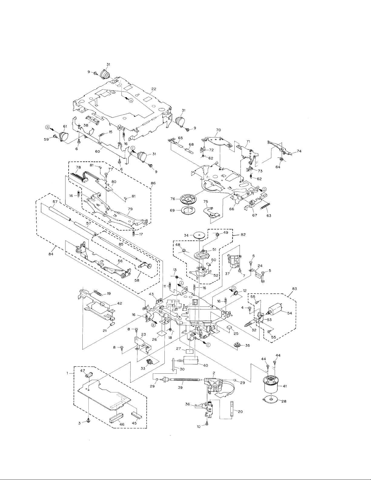
2.4 CD MECHANISM MODULE
Page 11

1 Control Unit(S7) CWX2332
2 Pickup Unit(Service) CXX1231
3 Screw IMS26P035FMC
4 Screw BMZ20P025FMC
5 Screw BMZ20P040FMC
6 Screw BSZ20P040FMC
7 Screw(M2×3) CBA1077
8 Screw(M2×2) CBA1250
9 Screw(M2×5) CBA1296
10 Screw(M2×3.85) CBA1362
11 Spring CBH1724
12 Spring CBH1729
13 Spring CBH1730
14 Spring CBH1731
15 Spring CBH1732
16 Spring CBH1745
17 Spring CBH1848
18 Spring CBH1849
19 Spring CBH1939
20 Spring CBL1214
21 Roller CLA2627
22 Frame CNC5796
23 Bracket CNC5871
* 24 Bracket CNC6376
25 Cushion CNM3917
26 Sheet CNM4873
* 27 Sheet CNM5116
28 PCB CNP4230
29 Bearing CNR1415
30 Belt CNT1071
31 Damper CNV3974
32 Gear CNV4128
33 Gear CNV4129
34 Gear CNV4857
35 Gear CNV4131
36 Holder CNV4663
37 Holder CNV5071
38 Guide CNV4484
39 Screw Unit CXA8699
40 CRG Motor Unit(M2) CXB3043
41 Motor Unit(M1) CXA8912
42 Lever Unit CXA9300
43 Chassis Unit CXB2574
44 Screw JFZ20P025FMC
45 Connector(CN101) CKS1953
46 Connector(CN701) CKS2774
47 Connector(CN801) CKS2196
48 Spring CBH1832
49 Spring CBH1833
50 Roller CLA2627
51 Arm CNV4136
52 Arm Unit CXA8565
53 Bracket CNC6056
54 Load Motor Unit(M3) CXA8702
55 Screw JFZ20P025FMC
56 Arm CNV4120
57 Roller CNV4509
58 Gear Unit CXA8701
59 Screw(M2×5) CBA1455
60 Frame CNC5797
61 Damper CNV3974
62 Spring CBH1736
63 Spring CBH1863
64 Spring CBH1945
65 Spring CBL1269
66 Arm CNC5799
67 Lever CNC6054
68 Spacer CNM3315
69 Sheet CNM4849
70 Arm CNV5436
71 Arm CNV4123
72 Arm CNV4124
73 Arm CNV4125
74 Arm CNV4138
75 Arm CNV4139
76 Clamper CNV4140
77 Screw(M2×2) CBA1250
78 Connector CDE4576
79 Arm CNC7383
* 80 Gathering PCB CNX2533
81 Photo-transistor(Q1, 2) CPT-230S-X
82 ELBO Arm Assy CXA8889
83 Load Motor Assy CXA8891
84 LO Arm Assy CXA8892
85 Shaft CLA3133
86 Guide Arm Assy CXB1851
7
CDS-9036ZT
- CD MECHANISM MODULE SECTION PARTS LIST
Mark No. Description Part No. Mark No. Description Part No.
Page 12
8
CDS-9036ZT
1
23
4
1234
D
C
B
A
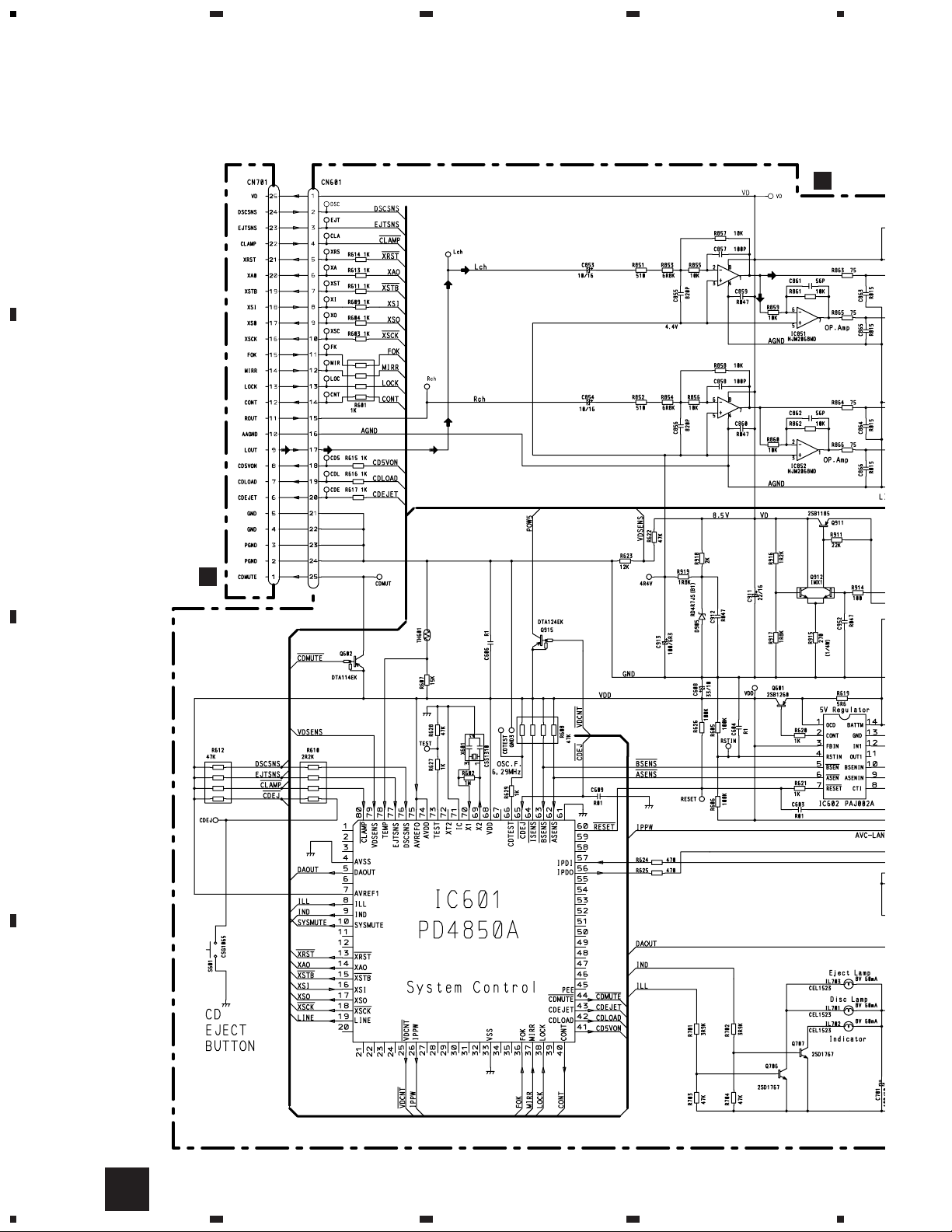
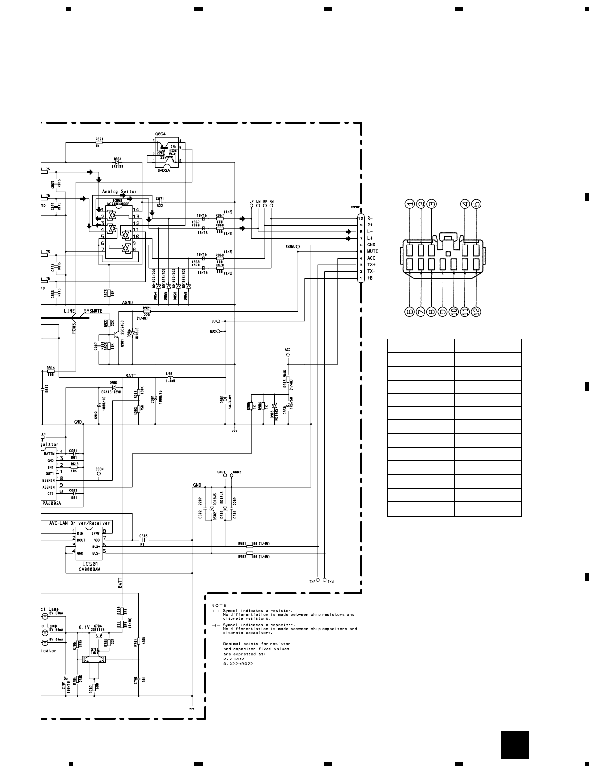
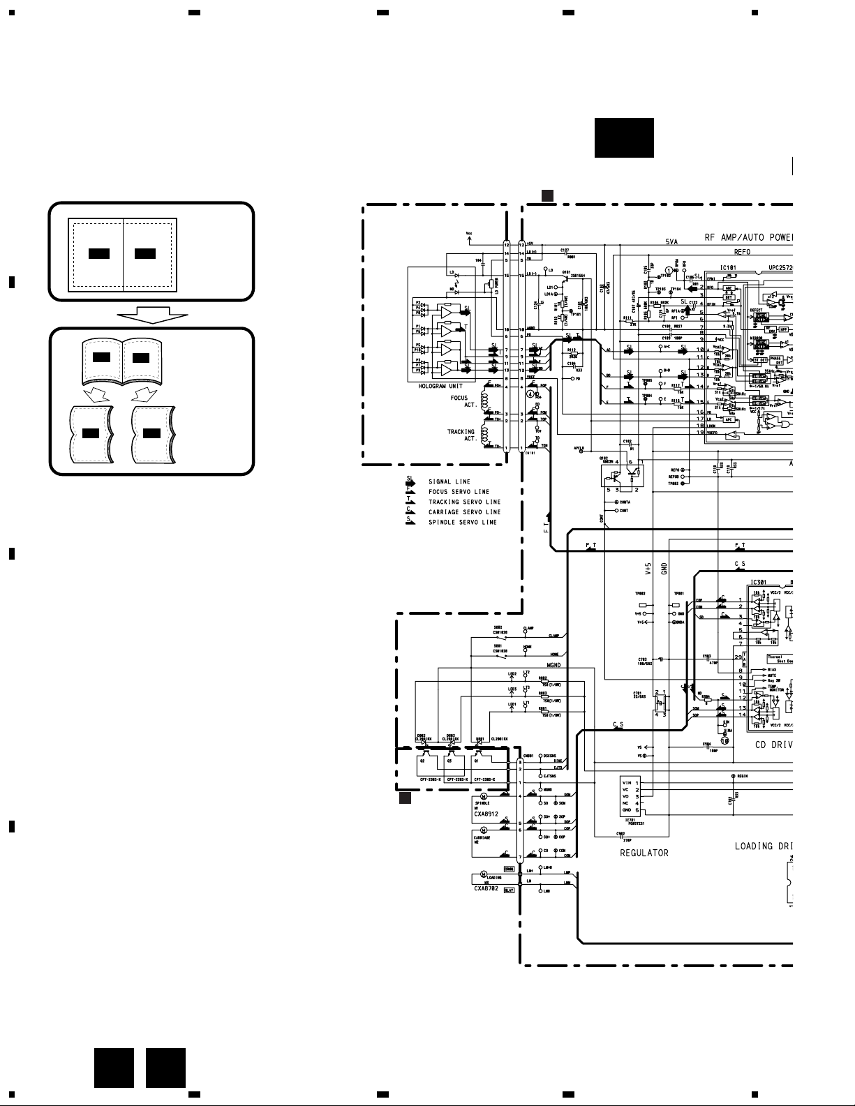
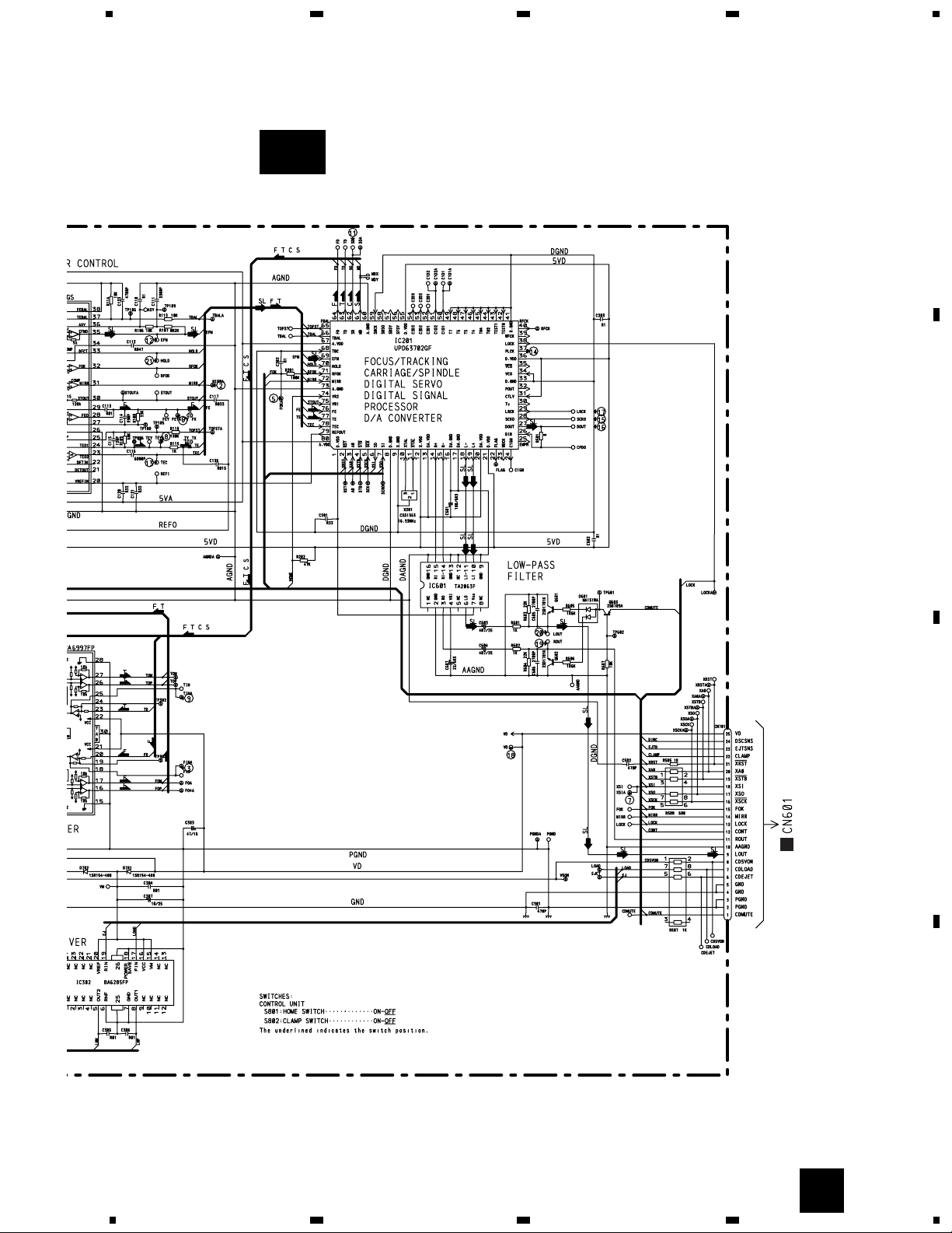
3. SCHEMATIC DIAGRAM
3.1 OVERALL CONNECTION DIAGRAM
Note: When ordering service parts, be sure to refer to “EXPLODED VIEWS AND PARTS LIST” or “ELECTRICAL PARTS
LIST”.
CONTR
A
CONTROL UNIT(S7)
B
A
Page 13
9
CDS-9036ZT
5
6
78
5
6
78
D
C
B
A
A
Connector No Description
1R+
2L+
3 SGND
4 MUTE
5+B
6R≠
7L≠
8 GND
9TX≠
10 TX+
11 NC
12 ACC
Page 14
10
CDS-9036ZT
1
23
4
1234
D
C
B
A
3.2 CD MECHANISM MODULE(GUIDE PAGE)
CONTROL UNIT(S7)
B
PICKUP UNIT(SERVICE)
C
PHOTO UNIT
CXB3043
A-a A-b
A-aA-a
A-b A-b
A-b A-b
A-a A-a
Large size
SCH diagram
Guide page
Detailed page
CB
B-a
Page 15
11
CDS-9036ZT
5
6
78
5
6
78
D
C
B
A
A
B
B-b
Page 16

12
CDS-9036ZT
1
23
4
234
D
C
B
A
1
B-a
B-a
B-b
CONTROL UNIT(S7)
B
PICKUP UNIT(SERVICE)
Page 17

13
CDS-9036ZT
5
6
78
5
6
7
D
C
B
A
8
B-a
C
B-a
B-b
C
PHOTO UNIT
CXB3043
Page 18

14
CDS-9036ZT
1
23
4
234
D
C
B
A
1
B-b
B-a
B-b
Page 19

15
CDS-9036ZT
5
6
78
5
6
7
D
C
B
A
8
B-b
B-a
B-b
A
Page 20

16
CDS-9036ZT
- Waveforms
Note:1. The encircled numbers denote measuring pointes in the circuit diagram.
2. Reference voltage
REFO:2.5V
1 RFO 0.5V/div. 0.5µs/div.
Normal mode: play
1 CH1: RFO 1V/div.
2 CH2: MIRR 5V/div.
Test mode: Tracking open
0.5ms/div.
1 CH1: RFO 1V/div.
2 CH2: MIRR 5V/div.
Normal mode: The defect part
passes 800µm
0.5ms/div.
3 CH1: FIN 0.5V/div.
4 CH2: FO+ 2V/div.
Test mode: No disc, Focus close
0.2s/div.
3 CH1: FIN 0.5V/div.
5 CH2: FOK 2V/div.
Normal mode: Focus close
0.2s/div.
6 CH1: FEY 0.5V/div.
7 CH2: XSI 2V/div.
Normal mode: Focus close
1ms/div.
REFO
→
8 CH1: TEY 0.5V/div.
9 CH2: TIN 0.5V/div.
Test mode: 32 tracks jump (FWD)
0.5ms/div.
8 CH1: TEY 0.5V/div.
9 CH2: TIN 0.5V/div.
Test mode: Single jump (FWD)
0.5ms/div.
8 CH1: TEY 0.5V/div.
9 CH2: TIN 0.5V/div.
Test mode: 100 tracks jump (FWD)
5ms/div.
6 CH1: FEY 0.1V/div.
3 CH2: FIN 0.2V/div.
Normal mode: Play
20ms/div.
3 CH1: FIN 0.5V/div.
0 CH2: SIN 1V/div.
Normal mode: Focus close (12cm)
0.5s/div.
3 CH1: FIN 0.5V/div.
0 CH2: SIN 1V/div.
Normal mode: Focus close (8cm)
0.5s/div.
GND
→
GND
→
REFO
→
REFO
→
REFO
→
REFO
→
GND
→
REFO
→
REFO
→
GND
→
REFO
→
REFO
→
REFO
→
REFO
→
REFO
→
REFO
→
REFO
→
REFO
→
REFO
→
REFO
→
REFO
→
REFO
→
Page 21

17
CDS-9036ZT
8 CH1: TEY 0.2V/div.
9 CH2: TIN 0.2V/div.
Normal mode: play
8 CH1: TEY 0.5V/div.
! CH2: SD 0.5V/div.
5ms/div.
0 SIN 0.5V/div. 0.1s/div.
Normal mode: Play (12cm)
0 SIN 1V/div. 10ms/div.
Long Search (12cm)
@ EFM 1V/div. 5µs/div.
Play
8 CH1: TEY 1V/div.
# CH2: TEC 1V/div.
Test mode: Focus close
Tracking open
2ms/div.
8 CH1: TEY 0.5V/div.
6 CH2: FEY 0.5V/div.
Normal mode:
AGC after focus close
0.2s/div.
$ PLCK 2V/div. 0.5µs/div.
Play
20ms/div.
% SCKO 2V/div. 1µs/div.
Play
^ Dout 2V/div. 10µs/div.
Play
& LRCK 2V/div. 20µs/div. * VD 5V/div. 50ms/div.
Normal mode: No disc
GND
→
REFO
→
REFO
→
GND
→
REFO
→
REFO
→
REFO
→
REFO
→
REFO
→
REFO
→
REFO
→
REFO
→
REFO
→
GND
→
REFO
→
GND
→
REFO
→
GND
→
REFO
→
GND
→
REFO
→
Page 22

18
CDS-9036ZT
( CH1: R OUT 1V/div.
) CH2: L OUT 1V/div.
Normal mode: Play (1kHz 0dB)
6 CH1: FEY 0.2V/div.
3 CH2: FIN 0.5V/div.
Normal mode: During AGC
1ms/div.
8 CH1: TEY 0.2V/div.
9 CH2: TIN 0.5V/div.
Normal mode: During AGC
1 CH1: RFO 1V/div.
⁄ CH2: HOLD 5V/div.
Normal mode: The defect part passes
800µm
0.2ms/div. 1ms/div.
0.5ms/div.
3 CH1: FIN 1V/div.
⁄ CH2: HOLD 5V/div.
Normal mode: The defect part passes
800µm
0.5ms/div.
GND
→
GND
→
REFO
→
REFO
→
REFO
→
REFO
→
REFO
→
REFO
→
Page 23

19
CDS-9036ZT
Page 24

20
CDS-9036ZT
1
23
4
234
D
C
B
A
1
4. PCB CONNECTION DIAGRAM
4.1 CONTROL UNIT
CONTROL UNIT
A
A
CD EJECT
B
CN701
CD TEST
Page 25

21
CDS-9036ZT
5
6
78
5
6
7
D
C
B
A
8
SIDE A
NOTE FOR PCB DIAGRAMS
1. The parts mounted on this PCB include all necessary parts for
several destination.
For further information for respective destinations, be sure to
check with the schematic diagram.
2. Viewpoint of PCB diagrams
A
Connector
Capacitor
SIDE A
P.C.Board
Chip Part
SIDE B
Page 26

22
CDS-9036ZT
1
23
4
234
D
C
B
A
1
CONTROL UNIT
A
A
Page 27

23
CDS-9036ZT
5
6
78
5
6
7
D
C
B
A
8
SIDE B
A
Page 28

24
CDS-9036ZT
1
23
4
1234
D
C
B
A
4.2 CONTROL UNIT(S7),PHOTO UNIT
SIDE A
B
C
CONTROL UNIT(S7)
B
PHOTO UNIT
C
PICKUP UNIT(SERVICE)
A
CN601
B
Page 29

25
CDS-9036ZT
D
C
B
A
1
2
34
1
2
34
SIDE B
B
CONTROL UNIT(S7)
B
C
Page 30

CDS-9036ZT
5. ELECTRICAL PARTS LIST
NOTES:
- Parts whose parts numbers are omitted are subject to being not supplied.
- The part numbers shown below indicate chip components.
Chip Resistor
RS1/_S___J,RS1/__S___J
Chip Capacitor (except for CQS.....)
CKS....., CCS....., CSZS.....
=====Circuit Symbol and No.===Part Name Part No.
--- ------ ------------------------------------------ -------------------------
Unit Number :CWX2332
Unit Name :Control Unit(S7)
IC 101 IC UPC2572GS
IC 201 IC UPD63702GF
IC 301 IC BA6997FP
IC 302 IC BA6285FP
IC 601 IC TA2063F
IC 701 IC PQ05TZ51
Q 101 Transistor 2SD1664
Q 102 Transistor UMD2N
Q 601 Transistor 2SD1781K
Q 602 Transistor 2SD1781K
Q 603 Transistor 2SB709A
D 601 Chip Diode MA151WA
D 701 Diode 1SR154-400
D 702 Diode 1SR154-400
D 801 Chip LED CL200IRX
D 802 Chip LED CL200IRX
D 803 Chip LED CL200IRX
X 201 Ceramic Resonator 16.93MHz CSS1363
S 801 Switch(Home) CSN1028
S 802 Switch(Clamp) CSN1028
RESISTORS
R 101 RS1/8S100J
R 102 RS1/8S120J
R 103 RS1/16S102J
R 104 RS1/16S822J
R 105 RS1/16S682J
R 106 RS1/16S183J
R 107 RS1/16S822J
R 108 RS1/16S333J
R 109 RS1/16S683J
R 110 RS1/16S134J
R 111 RS1/16S273J
R 112 RS1/16S222J
R 113 RS1/16S103J
R 114 RS1/16S103J
R 115 RS1/16S102J
R 116 RS1/16S163J
R 117 RS1/16S163J
R 201 RS1/16S104J
R 202 RS1/16S473J
R 304 RS1/16S0R0J
R 501 RS1/16S0R0J
R 505 RS1/16S102J
R 507 RA4C102J
R 508 RA4C681J
R 601 RS1/16S102J
R 602 RS1/16S102J
R 603 RS1/16S223J
R 604 RS1/16S223J
R 605 RS1/16S162J
R 606 RS1/16S162J
R 607 RS1/16S103J
R 801 RS1/8S751J
R 802 RS1/8S751J
R 803 RS1/8S751J
CAPACITORS
C 101 CEV101M6R3
C 102 CKSQYB104K16
C 103 CEV470M6R3
C 104 CKSYB334K16
C 105 CCSRCH330J50
C 106 CKSRYB103K25
C 107 CEV4R7M35
C 108 CKSQYB273K50
C 109 CCSRCH101J50
C 110 CKSQYB104K16
C 111 CKSRYB332K50
C 112 CKSQYB473K16
C 113 CKSRYB103K25
C 114 CKSRYB391K50
C 115 CCSRCH121J50
C 116 CKSRYB682K25
C 117 CKSRYB333K16
C 118 CKSYB334K16
C 119 CKSYB334K16
C 120 CKSYB334K16
C 121 CKSYB334K16
C 122 CKSQYB104K16
C 123 CKSRYB472K50
C 124 CKSQYB104K16
C 125 CCSRCH6R0D50
C 126 CKSRYB153K25
C 127 CCSRCH102J25
C 201 CKSYB334K16
C 202 CKSQYB104K16
C 203 CKSQYB104K16
C 303 CEV470M16
C 304 CKSRYB103K25
C 305 CKSRYB103K25
C 306 CKSRYB103K25
C 307 CEV100M25
C 502 CKSRYB471K50
C 601 CEV101M6R3
C 602 CKSQYB104K16
C 603 CEV4R7M35
C 604 CEV4R7M35
C 605 CKSRYB272K50
C 606 CKSRYB272K50
C 607 CEV220M6R3
C 701 22µF/6.3V CCH1233
C 702 CKSYB334K16
C 703 CEV101M6R3
C 901 CCSRCH471J50
=====Circuit Symbol and No.===Part Name Part No.
--- ------ ------------------------------------------ -------------------------
B
26
Page 31

C 902 CCSRCH271J50
C 903 CCSRCH471J50
C 904 CCSRCH101J50
Unit Number :CWM5461
Unit Name :Control Unit
MISCELLANEOUS
IC 501 IC CA0008AM
IC 601 IC PD4850A
IC 602 IC PAJ002A
IC 851 IC NJM2068MD
IC 852 IC NJM2068MD
IC 853 IC MC74HC4066F
Q 601 Transistor 2SB1260
Q 602 Transistor DTA114EK
Q 703 Transistor IMX1
Q 704 Transistor 2SB1185
Q 706 Transistor 2SD1767
Q 707 Transistor 2SD1767
Q 854 Transistor IMD2A
Q 901 Transistor 2SC2458
Q 911 Transistor 2SB1185
Q 912 Transistor IMX1
Q 915 Transistor DTA124EK
D 501 Diode RD18JS
D 502 Diode RD18JS
D 854 Zener Diode RD10ES(B2)
D 856 Zener Diode RD10ES(B2)
D 858 Zener Diode RD10ES(B2)
D 860 Zener Diode RD10ES(B2)
D 861 Diode 1SS133
D 901 Diode SM-3-02
D 902 Diode ERA15-02VH
D 903 Diode RD18JS
D 904 Diode RD18JS
D 905 Diode RD4R7JS(B1)
L 901 Choke Coil 1.4mH CTH1129
TH 601 Thermistor CCX1015
X 601 Ceramic Resonator 6.29MHz CSS1310
S 601 Switch(CD Eject) CSG1065
IL 701 Lamp 8V60mA CEL1523
IL 702 Lamp 8V60mA CEL1523
IL 703 Lamp 8V60mA CEL1523
RESISTORS
R 501 RD1/4PU101J
R 502 RD1/4PU101J
R 601 RA4C102J
R 602 RS1/10S105J
R 603 RS1/10S102J
R 604 RS1/10S102J
R 605 RS1/10S104J
R 606 RS1/10S104J
R 607 RS1/10S153J
R 608 RA4C473J
R 609 RS1/10S102J
R 610 RA4C222J
R 611 RS1/10S102J
R 612 RA4C473J
R 613 RS1/10S102J
R 614 RS1/10S102J
R 615 RS1/10S102J
R 616 RS1/10S102J
R 617 RS1/10S102J
R 618 RS1/10S103J
R 619 RS1/10S5R6J
R 620 RS1/10S102J
R 621 RS1/10S102J
R 622 RS1/10S473J
R 623 RS1/10S123J
R 624 RS1/10S471J
R 625 RS1/10S471J
R 626 RS1/10S104J
R 627 RS1/10S102J
R 628 RS1/10S473J
R 629 RS1/10S102J
R 701 RS1/10S392J
R 702 RS1/10S392J
R 703 RS1/10S473J
R 704 RS1/10S473J
R 705 RS1/10S152J
R 706 RS1/10S242J
R 707 RS1/10S681J
R 708 RS1/10S223J
R 709 RS1/10S472J
R 710 RD1/4PU3R9J
R 711 RD1/4PU3R9J
R 851 RS1/10S511J
R 852 RS1/10S511J
R 853 RS1/10S682J
R 854 RS1/10S682J
R 855 RS1/10S103J
R 856 RS1/10S103J
R 857 RS1/10S103J
R 858 RS1/10S103J
R 859 RS1/10S103J
R 860 RS1/10S103J
R 861 RS1/10S103J
R 862 RS1/10S103J
R 863 RS1/10S750J
R 864 RS1/10S750J
R 865 RS1/10S750J
R 866 RS1/10S750J
R 867 RS1/8S101J
R 868 RS1/8S101J
R 869 RS1/8S101J
R 870 RS1/8S101J
R 871 RS1/10S102J
R 873 RS1/10S103J
R 901 RS1/10S184J
R 902 RS1/10S753J
R 903 RD1/4PU242J
R 904 RN1/10SE1001D
R 905 RS1/10S102J
R 911 RS1/10S223J
R 914 RS1/10S101J
R 915 RD1/4PU271J
R 916 RS1/10S122J
R 917 RS1/10S182J
R 918 RS1/10S202J
R 919 RS1/10S182J
R 921 RD1/4PU221J
R 922 RS1/10S223J
R 923 RS1/10S103J
CAPACITORS
C 501 CKSQYB221K50
C 502 CKSQYB221K50
C 503 CKSQYB104K50
C 601 CKSQYB103K50
C 602 CKSQYB103K50
C 603 CKSQYB103K50
C 604 CKSQYB104K50
C 606 CKSQYB104K50
C 608 CSZST330M10
C 609 CKSQYB103K50
27
CDS-9036ZT
=====Circuit Symbol and No.===Part Name Part No.
--- ------ ------------------------------------------ -------------------------
=====Circuit Symbol and No.===Part Name Part No.
--- ------ ------------------------------------------ -------------------------
A
Page 32

C 701 CEJA101M10
C 702 CKSQYB103K50
C 853 CEJA100M16
C 854 CEJA100M16
C 855 CCSQCH821J50
C 856 CCSQCH821J50
C 857 CCSQCH101J50
C 858 CCSQCH101J50
C 859 CKSQYB473K50
C 860 CKSQYB473K50
C 861 CCSQCH560J50
C 862 CCSQCH560J50
C 863 CKSQYB153K50
C 864 CKSQYB153K50
C 865 CKSQYB153K50
C 866 CKSQYB153K50
C 867 CEJANP100M16
C 868 CEJANP100M16
C 869 CEJANP100M16
C 870 CEJANP100M16
C 871 CKSQYB224K16
C 901 1000µF/16V CCH1149
C 902 1000µF/16V CCH1149
C 907 CKSQYB102K50
C 911 CEJA220M16
C 912 CKSQYB473K50
C 913 CEJA101M6R3
C 950 CEJA1R5M50
C 952 CKSQYB473K50
Unit Number :
Unit Name :Photo Unit
Q 1 Photo-transistor CPT-230S-X
Q 2 Photo-transistor CPT-230S-X
Q 3 Photo-transistor CPT-230S-X
Miscellaneous Parts List
Pickup Unit(Service) CXX1231
M 1 Motor Unit(Spindle) CXA8912
M 2 CRG Motor Unit(S7)(Carriage) CXB3043
M 3 Load Motor Unit(S7)(Loading) CXA8702
28
CDS-9036ZT
=====Circuit Symbol and No.===Part Name Part No.
--- ------ ------------------------------------------ -------------------------
C
Page 33

29
CDS-9036ZT
1)Precautions
• This unit uses a single power supply (+5V) for the reg-
ulator. The signal reference potential, therefore, is
connected to REFO(approx. 2.5V) instead of GND.
If REFO and GND are connected to each other by mis-
take during adjustments, not only will it be impossible to measure the potential correctly, but the servo
will malfunction and a severe shock will be applied to
the pick-up. To avoid this, take special note of the following.
Do not connect the negative probe of the measuring
equipment to REFO and GND together. It is especially
important not to connect the channel 1 negative
probe of the oscilloscope to REFO with the channel 2
negative probe connected to GND.
Since the frame of the measuring instrument is usual-
ly at the same potential as the negative probe, change
the frame of the measuring instrument to floating status.
If by accident REFO comes in contact with GND,
immediately switch the regulator or power OFF.
• Always make sure the regulator is OFF when connect-
ing and disconnecting the various filters and wiring
required for measurements.
• Before proceeding to further adjustments and mea-
surements after switching regulator ON, let the player
run for about one minute to allow the circuits to stabilize.
• Since the protective systems in the unit's software are
rendered inoperative in test mode, be very careful to
avoid mechanical and /or electrical shocks to the system when making adjustment.
• Disc detection during loading and eject operations is
performed by means of a photo transistor in this
unit.Consequently, if the inside of the unit is exposed
to a strong light source when the outer casing is
removed for repairs or adjustment, the following malfunctions may occur.
*During PLAY, even if the eject button is pressed,the
disc will not be ejected and the unit will remain in
the PLAY mode.
*The unit will not load a disc.
When the unit malfunctions this way, either re-position the light source, move the unit or cover the
photo transistor.
• When loading and unloading discs during adjustment
procedures, always wait for the disc to be properly
clamped or ejected before pressing another key.
Otherwise, there is a risk of the actuator being
destroyed.
• Turn power off when pressing the button /FF or the
button REV key for focus search in the test mode. (Or
else lens may stick and the actuator may be damaged.)
2)Test Mode
The CDS-9036ZT/ES is used together with a CD con-
trol unit(KEH-M8276ZT/X1N/ES) to make adjustment.
For adjustment, keys of the CD control unit are used.
For your reference, how to enter Test mode and operate keys when using a CD control unit are shown below. The keys mentioned in the explanation of adjustment are of a CD control unit(KEH-M8276ZT/X1N/ES).
• Entering Test mode
Short-circuit the probes indicated as "CD TEST" on
the substrate of the CDS-9036ZT/ES, then set ACC or
BACK UP to ON.
• Cancelling Test mode
Set ACC or BACK UP to OFF.
• SINGLE/4TRK/10TRK/32TRK will continue to operate
even after the key is released.Tracking is closed the
moment C-MOVE is released.
• JUMP MODE resets to SINGLE as soon as power is
switched OFF.
6. ADJUSTMENT
6.1 CD
CD TEST
CONTROL UNIT(SIDE A)
Short-circuit these two probes.
Page 34

30
CDS-9036ZT
- Flow Chart
RAND
CD
Carriage move
or T. jump
Carriage move
or T. jump
SCAN
SCAN
TRACK+
C
RAND
TRACK+ TRACK-
RPT
RPT
RPT
RPT
RPT
TRACK+
RAND
SCAN
TRACK+ TRACK- TRACK-
TRACK+ TRACK-
SCAN
TRACK+
RAND
TRACK-
TRACK-
1-
CD
1-99
CD
1-00
CD
1-91
CD
1-01
CD
CD TEST
ACC, Back-up ON
Regulator OFF
Display
CD Player Select
Regulator ON
Display
Power ON
Regulator ON
Display
During regulator off, press the SCAN key
and the system will be put into the
new test mode.
*1
*1
Display
Tracking Close
CRG+
CRG–
Power
OFF
Power
OFF
Focus Close
*1
Focus Mode
Select
Power
OFF
Tracking Close
Tracking Close
Auto Adjustment Display
*4
Display
CRG+
CRG–
Tracking Balance
Adjustment
Tracking Open
AGC
*2
AGC Display
Select
Power
OFF
(in the case of
continuous jumping)
Tracking Open
Single
91(81)
10TRK
93(83)
32TRK
94(84)
C.MOVE
96(86)
4TRK
92(82)
100TRK
95(85)
T.JUMP MODE Select
Display
Normal focus close
100 TRK jump and carriage move
Normal display
*1 S curve check Focus EQ check
*2 Focus gain Track gain
*3
00 01 02
Tracking Close in a little while the keys are released
Focus bias
Normal display*4 Focus cancel Tracking offset Tracking balance
Spindle Close : Rough
Display
(99)
*3
Test Point Short
Page 35

31
CDS-9036ZT
• Note :
Unlike previous CD mechanism modules the grating angle of the pickup unit cannot be adjusted after the pickup
unit is changed. The pickup unit in the CD mechanism module is adjusted on the production line to match the CD
mechanism module and is thus the best adjusted pickup unit for the CD mechanism module. Changing the pickup
unit is thus best considered as a last resort. However, if the pickup unit must be changed, the grating should be
checked using the procedure below.
• Purpose :
To check that the grating is within an acceptable range.
• Symptoms of Mal-adjustment :
If the grating is off by a large amount symptoms such as being unable to close tracking, being unable to perform
track search operations, or track searching taking a long time, may appear.
• Method :
• Measuring Equipment • Oscilloscope, Two L.P.F.
• Measuring Points • E, F, REFOUT
• Disc • ABEX TCD-784
• Mode • TEST MODE
• Checking Procedure
1. In test mode, load the disc and switch the 5V regulator on.
2. Using the TRACK+ and TRACK- buttons, move the pickup unit to the innermost track.
3. Press key RAND to close focus, the display should read "91". Press key TRACK- to implement the tracking bal-
ance adjustment the display should now read "8x". Press key RAND 4 times. The display will change, returning
to "8x" on the fourth press.
4. As shown in the diagram above, monitor the LPF outputs using the oscilloscope and check that the phase differ-
ence is within 75° . Refer to the photographs supplied to determine the phase angle.
5. If the phase difference is determined to be greater than 75° try changing the PU unit to see if there is any
improvement. If, after trying this a number of times, the grating angle does not become less than 75° then the
mechanism should be judged to be at fault.
• Note
Because of eccentricity in the disc and a slight misalignment of the clamping center the grating waveform may be
seen to "wobble" ( the phase difference changes as the disc rotates). The angle specified above indicates the average angle.
• Hint
Reloading the disc changes the clamp position and may decrease the "wobble".
100kΩ
390pF
100kΩ
390pF
E
REFOUT
F
REFOUT
Xch Ych
OSCILLOSCOPE
L.P.F.
L.P.F.
CONTROL UNIT(S7)
6.2 CHECKING THE GRATING AFTER CHANGING THE PICKUP UNIT
Page 36

32
CDS-9036ZT
Grating waveform
Ech → Xch 20mV/div, AC
Fch → Ych 20mV/div, AC
45°
0°
75°
60°
30°
90°
Page 37

33
CDS-9036ZT
7. GENERAL INFORMATION
7.1 IC
- Pin Functions(PD4850A)
Pin No. Pin Name I/O Format Function and Operation
1-3 NC Not used
4 AVSS GND
5 DAOUT O Luminance adjustment output
6 NC Not used
7 AVREF1 I D/A converter reference voltage input
8 ILL O C Key illumination output
9 IND O C Indicator output
10 MUTE O C System mute output
11, 12 NC Not used
13 xrst O C LSI reset output for CD
14 XA0 O C LSI data identification control signal output for CD
15 xstb O C LSI strobe output for CD
16 XSI/TSI I LSI serial data input for CD
17 XSO/TSO O C LSI serial data output for CD
18 xsck/tck O C LSI serial clock output for CD
19 LINE O C Audio line output (analog SW)
20-24 NC Not used
25 vdcnt O C VD (CD module power) control output
26 IPPW O C IP-Bus driver power control output
27-32 NC Not used
33 VSS GND
34, 35 NC Not used
36 FOK I Focus OK input
37 MIRR I Mirror detector input
38 LOCK I Spindle lock detector input
39 NC Not used
40 CONT O C Servo driver power control output
41 CD5VON O C CD 5V power supply control output
42 CDLOAD O C Load motor load control output
43 CDEJET O C Load motor eject control output
44 cdmute O C CD mute output
45-55 NC Not used
56 IPDO O Data output for IP-Bus controller
57 IPDI I Data input for IP-Bus controller
58, 59 NC Not used
60 reset I Reset
61 NC GND
62 asens I ACC sense input
63 bsens I BACK UP sense input
64 isens I Illumination sense input
65 cdej I CD eject SW input
66 testcd CD test
67 NC Not used
68 VDD Microcomputer power supply
69 X2 O Oscillator output
70 X1 I Oscillator input
71 IC Connect to GND
72 XT2 Open
73 TEST/ten I Test mode/Test mode enable
74 AVDD I A/D converter analog power supply
75 AVREF0 I A/D converter reference voltage input
Page 38

34
CDS-9036ZT
IC's marked by* are MOS type.
Be careful in handling them because they are very
liable to be damaged by electrostatic induction.
*PD4850A
20
21
40
41
60
80
1
61
Pin No. Pin Name I/O Format Function and Operation
76 DSCSNS I Disc detect input
77 EJTSNS I Disc eject sense input
78 TEMP I Temperature detector input
79 VDSENS I VD overvoltage, ground-fault sensing input
80 clamp I Disc clamp sense input
BA6997FP
Page 39

35
CDS-9036ZT
7.2 DIAGNOSIS
7.2.1 SELF-DIAGNOSTIC FUNCTION
Normal
mode
System Check mode
The system runs a self-diagnosis and displays the
results (diagnostic codes).
•Max. 6 Diagnostic codes for each physical address (for
each connected device)
•Displays the current status (past errors not displayed)
Diagnosis Memory mode
The system displays historical operational errors
recorded for each physical address (for each device)
during normal operation in the past.
•Max. 6 Diagnostic codes for each physical address (for
each connected device)
LAN CHECK mode
The system displays the physical address of each
device connected to AVC-LAN.
•The device's own physical address is included.
Diagnosis Memory Clear
The system clears Diagnosis
Memory (the codes).
•After completing clearing, the sys-
tem goes to LAN CHECK mode.
6Memory Clear
Complete clearing
(automatic)
2End Diagnosis
3Go to System Check
4Return to LAN CHECK
5Go to Diagnosis Memory
4Return to LAN CHECK
2End Diagnosis
1Go to Diagnosis
2End Diagnosis
- Operation Specifications
KEH-M8276ZT/X1N/ES
1Go to Diagnosis Press the AM/SW key three times,
while holding down CH1 or CH6.
2End Diagnosis AM/SW key (Press and hold for 1.7 seconds.)
ACC OFF/ON
3Go to System Check CH1
4Return to LAN CHECK CH6
5Go to Diagnosis Memory CH2
6Memory Clear CH5 (Press and hold for 1.7 seconds.)
•Page up TRACK+
•Page down TRACK-
- AVC-LAN Diagnosis Mode
- Flowchart and Functions
Page 40

36
CDS-9036ZT
1 0123456789ABCDEF
1
3
2
Display
1—123
Serial No. Physical address
Example:2—190
The second device
connected is
an “audio H/U.”
1Device groups
1 : Controllers
2 : Video output devices
3 : Audio output devices
4 : Audio processing devices
5 : Information output devices
6 : Vehicle devices
- Physical Address Assignment
M.DISP
computer
AV
machine
1DIN
-TV
EMV
CD-ROM
navigation
Audio
ECU
Audio
H/U
Rear seatTVDisplay
with SW
Rear
control
SW
CD-CH
commander
MD-CH
commander
0
8
1-8
A-F
1 0123456789ABCDEF
2
Navigation
computer
ATIS
FM
multiple
TV tuner
CD-CH
with
video
0
1-F
1 0123456789ABCDEF
3
Radio
Cassette
Radio/cas-
sette with-
out CH
controller
CD-P
CD-CH
MD-P
MD-CH
DAT
DCC
TEL
ECU
0
8
1-7
9-F
1 0123456789ABCDEF
4
Equalizer
DSP
H. W
AMP
0
1-F
1 0123456789ABCDEF
5
GPS
receiver
ATIS
decoder
FM mul-
tiplex
decoder
CD-CH
MD-CH
CD-ROM
-CH
MD-ROM
-CH
0
1-F
1 0123456789ABCDEF
6
A/C
computer
Body
computer
0
1-F
Page 41

37
CDS-9036ZT
1
2
- Assignment of Diagnostic Codes
Display
1 12
Serial No. Diagnostic code
Example: 3D2
The third content of Diagnosis is
"No response to periodical
communications."
NOTES:
*1 Instruction to check for an error
in periodical communications is
interrupted.
- Items corresponding each model
<During Diagnosis Memory mode>
• CDS-9036ZT/ES(CD-P)
D1, D4, 60
<During System Check mode>
• CDS-9036ZT/ES(CD-P)
No Diagnostic code assigned 00
Common Diagnostic code
among devices
Diagnostic code specific to a particular device Diagnostic code for
communications
NO
ERR
+B error
ACC
error
MUTE
error
Micropro-
cessor
error
ROM
error
RAM
error
AM tuner
error
FM tuner
error
TV tuner
error
Cassette
deck
error
Cassette
deck EJT
failure
Tape entan-
gled in the
cassette
deck
Dirt in
cassette
deck
head
Broken
cassette
deck belt
CD deck
or CD-CH
error
CD, CH
EJT
failure
Dirt, scar
and upside-
down in
CD, CH
Detected
P.U tem-
perature
in CD, CH
Detected
overcur-
rent in
CD, CH
CH
tray errorCHelevator
error
CD, CH
clamp
error
MD deck
or MD-CH
error
MD, CHrMD, CHrMD, CHrMD, CHrMD, CH
recording
function
error
CHrMD, CH
r
Amplifier
error
DSP
error
EQ error
LCD
error
Switch
error
Antenna
error
Main
antenna
error
Sub
antenna
errorTVantenna
error
Antenna
selector
error
AUDIO
ECU
error
No response
to commu-
nications
Commu-
nications
failure
No response
to periodical
communica-
tions
*1
No response
to Diagnosis
0123456789ABCDEF
0
1
2
3
4
5
6
7
8
9
A
B
C
D/E
F
Page 42

38
CDS-9036ZT
LAN-CHECK mode System Check mode Diagnosis Memory mode
Beep
Display
• The system displays the physical address of each
device connected to AVC-LAN in sequence from
the lowest address.
Example: 1 — 1E0
Serial No. Physical address
(CD commander)
• When changing to another mode
Blinking "SYS" is displayed.
• After completing System Check
Displays a physical address.
••Identifies the device.
Example: H 150
Physical address (1DIN-TV)
Distinguishes from LAN-CHECK.
Displays a Diagnostic code.
••Identifies the type of error.
Example: 1 — d2
Serial No. Diagnostic code
(no response to periodical
communications)
Max. 6 for each physical address
Displays an auxiliary code
••Identifies the device involved in the error.
Example: 1 — 360
Serial No. Physical address (CD-CH)
1DIN-TV has recorded an error indicating there
is no response to periodical communications
in CD-CH.
1 — ———
When there is no physical address:
Displays a physical address.
The next lowest physical address
• When there is no Diagnostic code after completion
of System Check
00
The system changes as shown above, as this unit
does not include System Check.
• The system beeps three times
when changing to another mode.
• The system beeps once every time
a physical address is displayed.
• When changing to another mode
Blinking "CODE" is displayed.
• Then, "Latest periodical communications num-
ber" is displayed.
••Elapsed time at the current point is displayed.
Example: 1F
Elapsed time (31 minutes)
• The system displays a number from 00 to
FF (increases a digit every minute).
• When 256 minutes are reached, the system
returns to 00.
• Displays the details of Diagnosis.
Displays a physical address.
(Same as the left.)
Displays a periodical communications num-
ber.
••Displays the time when the error occurred.
Example: 1 — 02
Serial No. Elapsed time (2 minutes)
Displays Diagnostic code. (Same as the left.)
Displays an auxiliary code. (Same as the left.)
Displays a physical address.
• When there is no Diagnostic data:
00
• The system beeps three times
when changing to another mode.
• The system beeps once every time
a physical address is displayed.
• The system beeps three times
when starting up Diagnosis.
- Go to Diagnosis (Beep and Display)
Page 43

39
CDS-9036ZT
7.2.2 DISASSEMBLY
- Removing the Case(Not shown)
1.Insert and turn a flat screwdriver to remove the case.
- Removing the CD Mechanism Module
1.Remove the four screws.
2.Disconnect the connector.
3.Remove the CD Mechanism Module.
- Removing the Grille Assy
1.Disconnect the four stoppers indicated by arrows,
and then remove the Grille Assy.
-
Removing the Control Unit
1.Remove the two screws.
2.Stretch the four claws, and then remove the Control
Unit.
Page 44

40
CDS-9036ZT
7.2.3 TEST MODE
- Error Number Indication
If the CD should fail to operate in CD multi player or if an error has taken place during the operation and resulted in
an error, the player will enter into the error mode. And the cause of such error is numerically indicated.
This is armed at assisting an analysis or repair.
Error mode ............................... Mode (A), Mode (B)
(1) Examples of Display
• Mode (A) ............................... ErrX
• Mode (B) ............................... ErrXX
(2) Error Codes
*1 *2 Classification Description Cause/Detail
3 10 ELECTRIC Carriage home failure Carriage doesn't move to or from the innermost position
→Home switch failed and/or carriage immobile
1 11 ELECTRIC Focus failure Focus failed
→Defects, disc upside-down, severe vibration
12 ELECTRIC SETUP failure Spindle failed to lock or subcode unreadable
Subcode failure →Spindle defective, defect, severe vibration
14 ELECTRIC Mirror failure Unrecorded CD-R
The disc is upside-down, defects, vibration
17 ELECTRIC Set up failure AGC protect failed
→Defects, disc upside-down, severe vibration
30 ELECTRIC Search time out Failed to reach target address
→Carriage/tracking defective and/or defects
4 A0 SYSTEM Power failure Power overvoltage or short circuit detected
→Switching transistor defective and/or power abnormal
• *1 ........................................... Mode (A) error code
• *2 ........................................... Mode (B) error code
• CDS-9036ZT/ES : Mode (B)(Not used)
Normal play
Mode(A):
Displays an error code
Error
- New Test Mode(aging operation and setup analysis)
The single CD player plays in normal mode. After being set up, it will display FOK (focus), LOCK (spindle), subcode,
sound skip, protection against a mechanical error or the like, occurrence of an error, cause and time of an expiry, if
any, (and disc number).
During the setup, the CD software operation status (internal RAM and C-point)is displayed.
(1) How to enter NEW TEST Mode
See the test mode flow chart Page 30.
Page 45

41
CDS-9036ZT
(2) Relations of keys between TEST and NEW TEST Modes
Keys Test Mode New Test Mode
Regulator OFF Regulator ON PLAY in progress Error Occurred, Protection Activated
RPT Regulator ON Regulator OFF RPT Time of occurrence / cause of error select
TRACK+/FF FWD-KICK TRACK+/FF
TRACK-/REV REV-KICK TRACK-/REV
TRACK+ TRACKING CLOSE TRACK+
TRACK- TRACKING OPEN TRACK-
RAND FOCUS CLOSE RAND
SCAN To New Test FOCUS MODE SCAN
Mode Select
Operations, such as EJECT, CD ON/OFF, etc. are performed normally.
(3) Error Cause (Error Number) Code
Error Code Classification Mode Description Cause Detail
40 ELECTRIC PLAY FOK=L 100ms Put out of focus Scratch,
41 ELECTRIC PLAY LOCK=L 100ms Spindle unlock Stain,
42 ELECTRIC PLAY Subcode Failed to read subcode Vibration,
unacceptable 500ms Servo defect,
43 ELECTRIC PLAY Sound skipped Last address memory etc...
operated
(4) Indicating an Operation Status During Setup
Status No. Description Protection operation
01 Carriage home mode started None
02 Carriage moving inwards 10-second time out, Home switch failed
03 Carriage moving outwards 10-second time out, Home switch failed
05 Carriage moving outwards None
11 Setup started None
12 Spindle turn/Focus search started None
13 Waiting for focus closure (XSI=L) Failure to close focus
10,14 Waiting for focus closure (FOK=H) Failure to close focus
15, 16, 17 Focus closed, Tracking open Focus disrupted
18 During focus AGC Focus disrupted
Subcode waiting
19 During tracking AGC Disrupted focus
20 Waiting for MIRR, LOCK or subcode read Focus disrupted, MIRR NG, Failure to lock,
Carriage closed, SPINDLE=ADAPTIVE Failed to read subcode
(5) Example of Display.
• SET UP in progress
• Operation (PLAY, SEARCH, etc.) in progress perfectly
identical with that in the normal mode.
• Protection/Error upon occurrence
(a) Error number indicated
(b) Track number and
absolute time indicated
CD
11'11
CD
40'05
CD
XX'XX
Select the display
with the RPT key.
Page 46

42
CDS-9036ZT
7.2.4 CONNECTOR FUNCTION DESCRIPTION
Connector No Description
1R+
2L+
3 SGND
4 MUTE
5+B
6R≠
7L≠
8 GND
9TX≠
10 TX+
11 NC
12 ACC
Page 47

43
CDS-9036ZT
7.3 BLOCK DIAGRAM
B
A
C
Page 48

44
CDS-9036ZT
8. OPERATIONS AND SPECIFICATIONS
8.1 OPERATIONS
C9200
CD loading slot
CD eject button
DISC indicator light
12P
12P
6P
10P
10P 6P
CD player
AM/FM tuner/cassette player
Antenna plug(car side)
Wire harness(car side)
Connection diagram
Page 49

45
CDS-9036ZT
8.2 SPECIFICATIONS
Power source .................................... 13.2 V DC (10.5 – 16.0 V allowable)
Grounding system ................................................................ Negative type
Dimensions ................................................ 180 (W) x 50 (H) x 160 (D) mm
System .......................................................... Compact disc audio system
Usable discs .......................................................................... Compact disc
Signal format .............................................. Sampling frquency: 44.1 kHz
................................................Number of quantization bits: 16; linear
Frequency characteristics ........................................ 5 – 20,000 Hz (±1 dB)
Number of channel ...................................................................... 2 (stereo)
 Loading...