

Page 1
PIONEER CORPORATION 4-1, Meguro 1-Chome, Meguro-ku, Tokyo 153-8654, Japan
PIONEER ELECTRONICS (USA) INC. P.O.Box 1760, Long Beach, CA 90801-1760 U.S.A.
PIONEER EUROPE NV Haven 1087 Keetberglaan 1, 9120 Melsele, Belgium
PIONEER ELECTRONICS ASIACENTRE PTE.LTD. 253 Alexandra Road, #04-01, Singapore 159936
C PIONEER CORPORATION 2005
K-ZZB. JAN. 2005 Printed in Japan
ORDER NO.
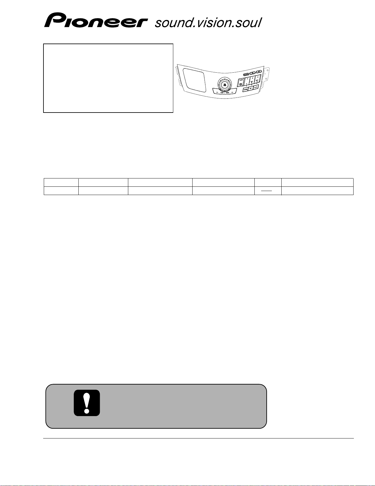
CRT3418
AUDIO CONTROL UNIT
CD-R4546ZH/XU/ES
For details, refer to "Important check points for good servicing".
CD-R4546ZH/XU/ES
VEHICLE DESTINATION PRODUCED AFTER OEM PART No. ID No. PIONEER MODEL No.
ODYSSEY CHINA February 2005 39050-SFJ-W010-M1 CD-R4546ZH/XU/ES
HONDA
Page 2

2
1
234
12
34
F
E
D
C
B
A
CD-R4546ZH/XU/ES
SAFETY INFORMATION
This service manual is intended for qualified service technicians; it is not meant for the casual do-it-yourselfer.
Qualified technicians have the necessary test equipment and tools, and have been trained to properly and safely repair
complex products such as those covered by this manual.
Improperly performed repairs can adversely affect the safety and reliability of the product and may void the warranty.
If you are not qualified to perform the repair of this product properly and safely, you should not risk trying to do so
and refer the repair to a qualified service technician.
- Service Precaution
You should conform to the regulations governing the product (safety, radio and noise, and other regulations),
and should keep the safety during servicing by following the safety instructions described in this manual.
Page 3
3
5
6
7
8
F
E
D
C
B
A
5
6
7
8
CD-R4546ZH/XU/ES
[Important Check Points for Good Servicing]
In this manual, procedures that must be performed during repairs are marked with the below symbol.
Please be sure to confirm and follow these procedures.
1. Product safety
Please conform to product regulations (such as safety and radiation regulations), and maintain a safe servicing environment by
following the safety instructions described in this manual.
1 Use specified parts for repair.
Use genuine parts. Be sure to use important parts for safety.
2 Do not perform modifications without proper instructions.
Please follow the specified safety methods when modification(addition/change of parts) is required due to interferences such as
radio/TV interference and foreign noise.
3 Make sure the soldering of repaired locations is properly performed.
When you solder while repairing, please be sure that there are no cold solder and other debris.
Soldering should be finished with the proper quantity. (Refer to the example)
4 Make sure the screws are tightly fastened.
Please be sure that all screws are fastened, and that there are no loose screws.
5 Make sure each connectors are correctly inserted.
Please be sure that all connectors are inserted, and that there are no imperfect insertion.
6 Make sure the wiring cables are set to their original state.
Please replace the wiring and cables to the original state after repairs.
In addition, be sure that there are no pinched wires, etc.
7 Make sure screws and soldering scraps do not remain inside the product.
Please check that neither solder debris nor screws remain inside the product.
8 There should be no semi-broken wires, scratches, melting, etc. on the coating of the power cord.
Damaged power cords may lead to fire accidents, so please be sure that there are no damages.
If you find a damaged power cord, please exchange it with a suitable one.
9 There should be no spark traces or similar marks on the power plug.
When spark traces or similar marks are found on the power supply plug, please check the connection and advise on secure
connections and suitable usage. Please exchange the power cord if necessary.
0 Safe environment should be secured during servicing.
When you perform repairs, please pay attention to static electricity, furniture, household articles, etc. in order to prevent injuries.
Please pay attention to your surroundings and repair safely.
2. Adjustments
To keep the original performance of the products, optimum adjustments and confirmation of characteristics within specification.
Adjustments should be performed in accordance with the procedures/instructions described in this manual.
4. Cleaning
For parts that require cleaning, such as optical pickups, tape deck heads, lenses and mirrors used in projection monitors, proper
cleaning should be performed to restore their performances.
3. Lubricants, Glues, and Replacement parts
Use grease and adhesives that are equal to the specified substance.
Make sure the proper amount is applied.
5. Shipping mode and Shipping screws
To protect products from damages or failures during transit, the shipping mode should be set or the shipping screws should be
installed before shipment. Please be sure to follow this method especially if it is specified in this manual.
Page 4

4
1
234
12
34
F
E
D
C
B
A
CD-R4546ZH/XU/ES
CONTENTS
SAFETY INFORMATION............................................2
1. SPECIFICATIONS .......................................................4
2. EXPLODED VIEWS AND PARTS LIST ......................5
2.1 PACKING..............................................................5
2.2 EXTERIOR............................................................6
3. SCHEMATIC DIAGRAM.............................................8
3.1 OVERALL CONNECTION DIAGRAM..................8
4. PCB CONNECTION DIAGRAM................................10
4.1 CONTROL PCB ..................................................10
4.2 SWITCH PCB and ENCODER PCB....................12
5. ELECTRICAL PARTS LIST........................................14
6. ADJUSTMENT.........................................................16
7. GENERAL INFORMATION.......................................17
7.1 DIAGNOSIS .......................................................17
7.1.1 DISASSEMBLY.........................................17
7.1.2 CONNECTOR FUNCTION DESCRIPTION ......18
7.2EXPLANATION...................................................19
7.3.1 SYSTEM BLOCK DIAGRAM.....................19
8. OPERATIONS ...........................................................20
1. SPECIFICATIONS
Grounding . . . . . . . . . . . . . . . .Negative type
Weight . . . . . . . . . . . . . . . . . . .0.41kg
Page 5
5
5
6
7
8
F
E
D
C
B
A
5
6
7
8
CD-R4546ZH/XU/ES
- PACKING SECTION PARTS LIST
NOTE:
- Parts marked by “*” are generally unavailable because they are not in our Master Spare Parts List.
- The > mark found on some component parts indicates the importance of the safety factor of the part.
Therefore, when replacing, be sure to use parts of identical designation.
- Screws adjacent to ∇ mark on the product are used for disassembly.
- For the applying amount of lubricants or glue, follow the instructions in this manual.
( In the case of no amount instructions, apply as you think it appropriate.)
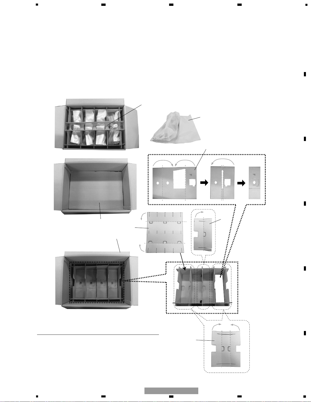
1 Protector CHP2932
2 Cover CEG1145
3 Protector CHP2928
4 Protector CHP2952
5 Protector CHP2929
6 Protector CHP2930
7 Protector CHP2931
8 Contain Box CHL5405
Mark No. Description Part No.
2. EXPLODED VIEWS AND PARTS LIST
2.1 PACKING
UPPER STAGE
LOWER STAGE
1
2
3
7
5
8
4
6
Page 6
6
1
234
12
34
F
E
D
C
B
A
CD-R4546ZH/XU/ES
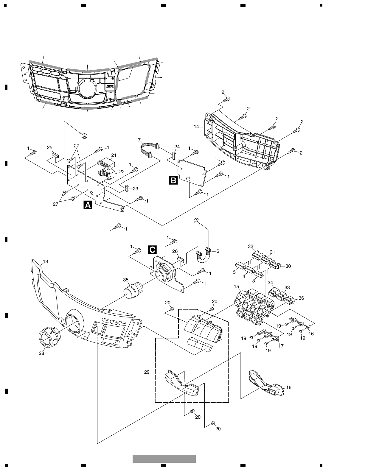
2.2 EXTERIOR
12
11
11
9
8
9
8
9
8
8
8
9
10
8
Page 7

7
5
6
7
8
F
E
D
C
B
A
5
6
7
8
CD-R4546ZH/XU/ES
1 Screw BPZ26P080FTC
2 Screw BPZ26P100FTC
3 Button(AM) CAC9356
4 Button(FM) CAC9357
5 Button(CD/AUX) CAC9358
6 Cord Assy CDE7458
7 Cord Assy CDE7307
8 Sheet CNM9260
9 Sheet CNM9261
10 Sheet CNM9262
11 Sheet CNM9263
12 Sheet CNM9264
13 Grille CNS8070
14 Cover CNV8228
15 Holder CNV8229
16 Pin CNV8230
17 Pin CNV8231
18 Holder CNV8351
19 Cushion CNV8418
20 Cap CNV8419
21 Plug(CN902) CKM1423
22 Plug(CN901) CKM1424
23 Connector(CN904) CKS2197
24 Connector(CN981) CKS2197
25 Connector(CN903) CKS2198
26 Connector(CN951) CKS2198
27 Screw PRZ30P060FTC
28 Knob Unit CXC3063
29 Button Assy CXC3755
30 Slider Unit CXC3756
31 Slider Unit CXC3757
32 Slider Unit CXC3758
33 Slider Unit CXC3760
34 Slider Unit CXC3761
35 Button Unit CXC3762
36 Slider Unit CXC4996
Mark No. Description Part No.
- EXTERIOR SECTION PARTS LIST
Page 8

8
1
234
12
34
F
E
D
C
B
A
CD-R4546ZH/XU/ES
Note: When ordering service parts, be sure to refer to " EXPLODED VIEWS AND PARTS LIST" or
"ELECTRICAL PARTS LIST".
A B
B
A
CONTROL PCB
KEY CONTROLLER
3. SCHEMATIC DIAGRAM
3.1 OVERALL CONNECTION DIAGRAM
Page 9

9
5
6
7
8
F
E
D
C
B
A
5
6
7
8
CD-R4546ZH/XU/ES
B CA
Decimal points for resistor
and capacitor fixed values
are expressed as :
2.2 2R2
0.022 R022
←
←
Symbol indicates a resistor.
No differentiation is made between chip resistors and
discrete resistors.
NOTE :
Symbol indicates a capacitor.
No differentiation is made between chip capacitors and
discrete capacitors.
B
SWITCH PCB
C
ENCODER PCB
Keyboard Unit
Consists of
Control PCB
Switch PCB
Encoder PCB
ENCODER
VOL
Page 10

A
Capacitor
Connector
P.C.Board
Chip Part
A
CONTROL PCB
SIDE B
SIDE A
NOTE FOR PCB DIAGRAMS
1.The parts mounted on this PCB
include all necessary parts for
several destination.
For further information for
respective destinations, be sure
to check with the schematic dia gram.
2.Viewpoint of PCB diagrams
SIDE A
CLOCK
RPT
SOUND
A.SEL
SCAN
10
1
234
12
34
F
E
D
C
B
A
CD-R4546ZH/XU/ES
4. PCB CONNECTION DIAGRAM
4.1 CONTROL PCB
Page 11

11
5
6
7
8
F
E
D
C
B
A
5
6
7
8
CD-R4546ZH/XU/ES
A
A
CONTROL PCB
SIDE B
B
CN981
C
CN951
DISPLAY UNIT
(OTHER COMPANY)
DEX-MG6157ZH/XU/ES
Page 12

12
1
234
12
34
F
E
D
C
B
A
CD-R4546ZH/XU/ES
B
B
SWITCH PCB
C
ENCODER PCB
SIDE A
SIDE A
C
VOL
PWR
TUNE+
TUNE-
6
5
4
CD/AUX
FM
AM
1
2
3
4.2 SWITCH PCB and ENCODER PCB
Page 13

13
5
6
7
8
F
E
D
C
B
A
5
6
7
8
CD-R4546ZH/XU/ES
B
B
SWITCH PCB
C
ENCODER PCB
SIDE B
SIDE B
C
A
CN904
A
CN903
Page 14

Keyboard Unit
Consists of
Control PCB
Switch PCB
Encoder PCB
Unit Number:
Unit Name : Keyboard Unit
MISCELLANEOUS
IC 901 (A,18,88) IC LC75853NE
D 901 (A,51,134) LED NSCB017R2-4328
D 902 (A,30,115) LED NSCB017R2-4328
D 903 (A,42,174) LED NSCB017R2-4328
D 904 (A,46,154) LED NSCB017R2-4328
D 906 (A,31,87) Diode UDZS6R8(B)
D 907 (A,19,46) Diode MA153
D 908 (A,19,51) Diode MA153
D 909 (A,19,57) Diode MA153
D 910 (A,19,62) Diode MA153
D 911 (B,11,28) Diode MA153
D 912 (B,16,30) Diode MA153
D 951 (A,40,10) LED NSCB017R2-4328
D 952 (A,51,40) LED NSCB017R2-4328
D 953 (A,74,10) LED NSCB017R2-4328
D 954 (A,62,40) LED NSCB017R2-4328
D 981 (A,66,32) LED NSCB017R2-4328
D 982 (A,71,65) LED NSCB017R2-4329
D 983 (A,46,27) LED NSCB017R2-4328
D 984 (A,46,59) LED NSCB017R2-4329
D 985 (A,26,23) LED NSCB017R2-4328
D 986 (A,22,54) LED NSCB017R2-4329
L 901 (A,36,91) Inductor LCYA100J2520
S 901 (A,6,120) Push Switch CSG1168
S 902 (A,43,113) Push Switch CSG1168
S 903 (A,56,134) Push Switch CSG1169
S 904 (A,47,174) Push Switch CSG1169
S 905 (A,52,154) Push Switch CSG1169
S 951 (A,57,40) Rotary Switch CSD1101
S 952 (A,57,40) Push Switch CSG1169
S 953 (A,90,17) Push Switch CSG1169
S 954 (A,24,17) Push Switch CSG1169
S 981 (A,76,66) Push Switch CSG1169
S 982 (A,52,60) Push Switch CSG1169
S 983 (A,27,55) Push Switch CSG1169
S 984 (A,75,55) Push Switch CSG1168
S 985 (A,55,50) Push Switch CSG1168
S 986 (A,35,46) Push Switch CSG1168
S 987 (A,59,19) Push Switch CSG1168
S 988 (A,39,14) Push Switch CSG1168
S 989 (A,19,10) Push Switch CSG1168
RESISTORS
R 901 (A,31,91) RS1/16S683J
R 902 (A,29,94) RS1/16S472J
R 904 (A,31,77) RS1/16S682J
R 905 (A,31,79) RS1/16S682J
R 906 (A,30,81) RS1/16S682J
R 907 (A,31,82) RS1/16S682J
R 908 (A,31,84) RS1/16S682J
R 909 (B,24,29) RS1/16S103J
R 910 (B,21,27) RS1/16S103J
R 911 (B,40,113) RS1/10S102J
R 912 (B,52,147) RS1/10S272J
R 913 (B,57,128) RS1/10S182J
R 914 (B,49,167) RS1/10S272J
R 915 (A,25,46) RS1/10S152J
R 916 (A,25,51) RS1/10S152J
R 917 (A,25,56) RS1/10S152J
R 918 (A,25,58) RS1/10S152J
R 919 (A,51,58) RS1/10S152J
R 920 (A,51,61) RS1/10S152J
R 921 (A,18,77) RS1/16S222J
R 922 (A,21,76) RS1/16S222J
R 923 (A,23,76) RS1/16S222J
R 924 (A,24,76) RS1/16S222J
R 925 (A,26,76) RS1/16S222J
R 926 (B,40,118) RS1/10S821J
R 927 (B,52,142) RS1/10S122J
R 928 (B,57,123) RS1/10S102J
R 929 (B,49,161) RS1/10S122J
R 931 (B,21,74) RS1/16S0R0J
R 932 (B,21,71) RS1/16S0R0J
R 933 (B,34,71) RS1/16S0R0J
R 934 (B,32,74) RS1/16S0R0J
R 935 (B,27,49) RS1/16S0R0J
R 936 (B,27,52) RS1/16S0R0J
R 937 (B,27,54) RS1/16S0R0J
R 951 (A,32,12) RS1/10S561J
R 952 (A,30,48) RS1/10S681J
R 954 (A,32,17) RS1/10S681J
R 955 (A,30,43) RS1/10S561J
R 981 (B,60,60) RS1/10S122J
R 982 (B,43,56) RS1/10S102J
R 983 (B,23,53) RS1/10S681J
R 984 (B,61,30) RS1/10S122J
R 985 (B,40,30) RS1/10S122J
R 986 (B,24,30) RS1/10S561J
14
1
234
12
34
F
E
D
C
B
A
CD-R4546ZH/XU/ES
=====Circuit Symbol and No.===Part Name Part No.
--- ------ ------------------------------------------ -------------------------
=====Circuit Symbol and No.===Part Name Part No.
--- ------ ------------------------------------------ -------------------------
A
5. ELECTRICAL PARTS LIST
NOTE:
Parts whose parts numbers are omitted are subject to being not supplied.
The part numbers shown below indicate chip components.
Chip Resistor
RS1/_S___J,RS1/__S___J
Chip Capacitor (except for CQS.....)
CKS....., CCS....., CSZS.....
The > mark found on some component parts indicatesthe importance of the safety factor of the part.
Therefore, when replacing, be sure to use parts of identical designation.
Meaning of the figures and others in the parentheses in the parts list.
Example) IC 301 is on the point (face A, 91 of x-axis, and 111 of y-axis) of the corresponding
PC board.
IC 301 (A, 91, 111) IC NJM2068V
B C
Page 15

15
5
6
7
8
F
E
D
C
B
A
5
6
7
8
CD-R4546ZH/XU/ES
R 987 (B,63,60) RS1/10S122J
R 988 (B,46,56) RS1/10S821J
R 989 (B,26,53) RS1/10S821J
R 990 (B,58,30) RS1/10S122J
R 991 (B,37,30) RS1/10S102J
R 992 (B,21,30) RS1/10S122J
CAPACITORS
C 901 (A,33,91) CCSRCH821J50
C 902 (A,29,89) CKSRYB103K50
C 903 (B,12,90) CEVW470M10
C 906 (A,52,139) CKSRYB104K25
C 907 (A,31,112) CKSRYB104K25
C 908 (A,43,178) CKSRYB104K25
C 909 (A,46,159) CKSRYB104K25
C 911 (A,19,48) CKSRYB102K50
C 912 (A,19,54) CCSRCH470J50
C 913 (A,19,59) CCSRCH101J50
C 920 (A,31,31) CKSQYB224K16
C 951 (A,39,13) CKSRYB104K25
C 952 (A,48,40) CKSRYB104K25
C 953 (A,75,13) CKSRYB104K25
C 954 (A,65,40) CKSRYB104K25
C 957 (B,44,57) CKSRYB103K50
C 958 (B,47,57) CKSRYB103K50
C 981 (A,63,32) CKSRYB104K25
C 982 (A,67,64) CKSRYB104K25
C 983 (A,43,27) CKSRYB104K25
C 984 (A,43,59) CKSRYB104K25
C 985 (A,23,23) CKSRYB104K25
C 986 (A,18,53) CKSRYB104K25
=====Circuit Symbol and No.===Part Name Part No.
--- ------ ------------------------------------------ -------------------------
Page 16

16
1
234
12
34
F
E
D
C
B
A
CD-R4546ZH/XU/ES
6. ADJUSTMENT
Connection Diagram
GGD1097
GGD1351
14P
GA-NET
ANT
3P
(GT-13)
AUDIO
6CD TUNER
DEX-MG6157ZH/XU/ES
AUX
14P
GGD1352
GGD1353
20P
16P
ILLUMINATION
CONTROLLER
GGD1350
KEY DRIVER
CONTROL
POWER
14P
AMPLIFIER
GM-6157ZH/XU/ES
20P
GGD1140
SPEAKER
&POWER
AUDIO CONTROLLER
CD-R4546ZH/XU/ES
14P
10P
AUDIO
DISPLAY
(Made by Nippon Seiki)
10P (D-2)
LCD DRIVER
CONTROL
LCD BL+/BL-
Page 17

17
5
6
7
8
F
E
D
C
B
A
5
6
7
8
CD-R4546ZH/XU/ES
7. GENERAL INFORMATION
7.1 DIAGNOSIS
7.1.1 DISASSEMBLY
1
1
- Removing the Cover (Fig.1)
- Removing the Switch PCB (Fig.2)
Remove the five screws and then
remove the Cover.
Remove the four screws.
Fig.1
Fig.2
Cover
1
- Removing the Encoder PCB (Fig.3, 4)
Remove the four screws and then
remove the Encoder PCB (Fig.3).
1
1
1
1
Fig.4
Remove the Knob Unit and then remove
the Button Unit (Fig.4).
Control PCB
Switch PCB
1
2
1
1
2
1
Button Unit
Knob Unit
1
2
2
2
- Removing the Control PCB (Fig.2)
Remove the five screws and then
remove the Control PCB.
1
1
1
1
Fig.3
Disconnect the connector and then remove the
Switch PCB.
2
Encoder PCB
Page 18

18
1
234
12
34
F
E
D
C
B
A
CD-R4546ZH/XU/ES
7.1.2 CONNECTOR FUNCTION DESCRIPTION
9
11
10
9
8
7
1
3
2
12
13
14
5
6
4
10
1. 5V
2. ILL+
3. ILL-
4. EN+
5. EN-
6. SGND1
7. 5V GND
8. CE
9. INH
10. CLOCK
8
7
1. 5V GND
2. 5V
3. NC
4. INH
5. CLOCK
6. DATA1
7. CE
8. SGND1
9. NC
10. NC
5
4
6
3
1
2
11. DATA1
12. DATA2
13. SGND2
14. NC
Page 19

19
5
6
7
8
F
E
D
C
B
A
5
6
7
8
CD-R4546ZH/XU/ES
7.2 EXPLANATION
7.2 SYSTEM BLOCK DIAGRAM
< HEAD UNIT SIDE > < SUB DISPLAY SIDE >
5V GND
5V
INH
CLOCK
DATA1
DATA2(KEY DATA)
ENCORDOR+
ENCORDOR-
ILL+
ILLLED
KNOB ILLUMINATION
ENCODER
CASE
KEY SCAN DRIVER
(LC75853)
KEY
MAIN ANT
ANTENNA
AMP
AUX
FROM VEHICLES
ILLUMINATION
CONTROLLER
SW+B
CIRCUIT
AM TUNER
FM TUNER
6CD PLAYER
AUX
INPUT
GA-NET
CONTROL
CIRCUIT
NOISE
CANCELLER
POWER
SUPPLY
DEX-MG6157ZH/XU/ES
SELECTOR
12V BATTERY
DSP
6CD PLAYER
CONTROL CIRCUIT
ELECTRONIC VOLUME
VOLUME
SYSTEM
CONTROLLER
CONVERTER
TUNER CONTROL
CIRCUIT
SWITCH PANEL
SECTSON
CD-R4546ZH/XU/ES
D/A
POWER SUPPLY
POWER SUPPLY(5V)
MUTE CONTROL
CIRCUIT
BACKLIGHT
INTERFACE
KEY
PRE
AMP
POWER
AMP
4CH
PRE OUT
STEERING
REMOTE CONTROL
DISPLAY
(LCD)
SUB DISPLAY
Page 20

20
1
234
12
34
F
E
D
C
B
A
CD-R4546ZH/XU/ES
8. OPERATIONS
CD→GA-NET CD CHANGER→AUX
POWER/
VOLUME
TRACK SCAN
DISC SCAN
TRACK UP/DOWN
CUE/REV
RANDOM PLAY
TRACK REPEAT
DISC REPEAT
- CD
DISC SELECT(1-6)
- GA-NET CD CHANGER CONTROL
CD→GA-NET CD CHANGER→AUX
POWER/
VOLUME
TRACK SCAN
DISC SCAN
TRACK UP/DOWN
CUE/REV
RANDOM PLAY
TRACK REPEAT
DISC REPEAT
DISC SELECT(DISC+,DISC-)
Page 21

21
5
6
7
8
F
E
D
C
B
A
5
6
7
8
CD-R4546ZH/XU/ES
BAS→TRE→FAD→BAL
CLOCK
AMSEEK SCAN
FM1→FM2
MANUAL TUNING/
SEEK TUNING
AUTOMATIC PRESET
MEMORY
PRESET CHANNEL CALL/
PRESET CHANNEL MEMORY
- Tuner
- Audio
POWER/
VOLUME
Page 22

22
1
234
12
34
F
E
D
C
B
A
CD-R4546ZH/XU/ES
- Jig List
Name Jig No. Remarks
Extention Cord GGD1097 GA-NET Cable
Extention Cord GGD1351 Antenna Cable
Extention Cord GGD1352 AUX Connector
Extention Cord GGD1350 System Cable
Extention Cord GGD1353 Pre-out Power Cable
Extention Cord GGD1140 Power Supply Cable
 Loading...