

Pioneer CDJ-800 Mk2 Service manual
PIONEER CORPORATION 4-1, Meguro 1-chome, Meguro-ku, Tokyo 153-8654, Japan
PIONEER ELECTRONICS (USA) INC. P.O. Box 1760, Long Beach, CA 90801-1760, U.S.A.
PIONEER EUROPE NV Haven 1087, Keetberglaan 1, 9120 Melsele, Belgium
PIONEER ELECTRONICS ASIACENTRE PTE. LTD. 253 Alexandra Road, #04-01, Singapore 159936
PIONEER CORPORATION 2006
ORDER NO.
RRV3364
CDJ-800MK2
COMPACT DISC PLAYER
CDJ-800MK2
THIS MANUAL IS APPLICABLE TO THE FOLLOWING MODEL(S) AND TYPE(S).
Model Type Power Requirement Remarks
CDJ-800MK2 KUCXJ AC 120 V
CDJ-800MK2 WYXJ5 AC 220 – 240 V
CDJ-800MK2 RLFXJ AC 110-120 V / 220-240 V
For details, refer to "Important symbols for good services" .
T-ZZR JUNE 2006 printed in Japan
-
1234
SAFETY INFORMATION
A
This service manual is intended for qualified service technicians ; it is not meant for the casual do-it
yourselfer. Qualified technicians have the necessary test equipment and tools, and have been trained
to properly and safely repair complex products such as those covered by this manual.
Improperly performed repairs can adversely affect the safety and reliability of the product and may
void the warranty. If you are not qualified to perform the repair of this product properly and safely, you
should not risk trying to do so and refer the repair to a qualified service technician.
WARNING
This product contains lead in solder and certain electrical parts contain chemicals which are known to the state of California to
causecancer, birth defects or other reproductive harm.
B
NOTICE
(FOR CANADIAN MODEL ONLY)
Fuse symbols (fast operating fuse) and/or (slow operating fuse) on PCB indicate that replacement
parts must be of identical designation.
REMARQUE
(POUR MODÈLE CANADIEN SEULEMENT)
Les symboles de fusible (fusible de type rapide) et/ou (fusible de type lent) sur CCI indiquent que
les pièces de remplacement doivent avoir la même désignation.
Health & Safety Code Section 25249.6 – Proposition 65
C
(FOR USA MODEL ONLY)
1. SAFETY PRECAUTIONS
The following check should be performed for the
continued protection of the customer and
service technician.
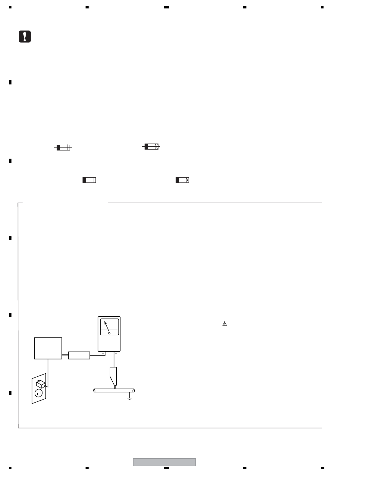
LEAKAGE CURRENT CHECK
Measure leakage current to a known earth ground (waterpipe
, conduit, etc.) by connecting a leakage current tester
such as Simpson Model 229-2 or equivalent between the
D
earth ground and all exposed metal parts of the appliance
(input/output terminals, screwheads, metal overlays, control
shaft, etc.). Plug the AC line cord of the appliance directly
into a 120V AC 60Hz outlet and turn the AC power switch
on. Any current measured must not exceed 0.5mA.
Reading should
Leakage
Device
under
E
test
Also test with
plug reversed
(Using AC adapter
plug as required)
Test all
exposed metal
surfaces
current
tester
not be above
0.5mA
Earth
ground
ANY MEASUREMENTS NOT WITHIN THE LIMITS
OUTLINED ABOVE ARE INDICATIVE OF A POTENTIAL
SHOCK HAZARD AND MUST BE CORRECTED BEFORE
RETURNING THE APPLIANCE TO THE CUSTOMER.
2. PRODUCT SAFETY NOTICE
Many electrical and mechanical parts in the appliance
have special safety related characteristics. These are
often not evident from visual inspection nor the protection
afforded by them necessarily can be obtained by using
replacement components rated for voltage, wattage, etc.
Replacement parts which have these special safety
characteristics are identified in this Service Manual.
Electrical components having such features are identified
by marking with a on the schematics and on the parts list
in this Service Manual.
The use of a substitute replacement component which does
not have the same safety characteristics as the PIONEER
recommended replacement one, shown in the parts list in
this Service Manual, may create shock, fire, or other hazards.
Product Safety is continuously under review and new
instructions are issued from time to time. For the latest
information, always consult the current PIONEER Service
Manual. A subscription to, or additional copies of, PIONEER
Service Manual may be obtained at a nominal charge
from PIONEER.
AC Leakage Test
F
2
1234
CDJ-800MK2
5678
THIS PIONEER APPARATUS CONTAINS
IMPORTANT
LASER OF CLASS 1.
SERVICING OPERATION OF THE APPARATUS
SHOULD BE DONE BY A SPECIALLY
INSTRUCTED PERSON.
The AEL(accessible emission level) of the laser power output is less then CLASS 1
but the laser component is capable of emitting radiation exceeding the limit for
CLASS 1.
A specially instructed person should servicing operation of the apparatus.
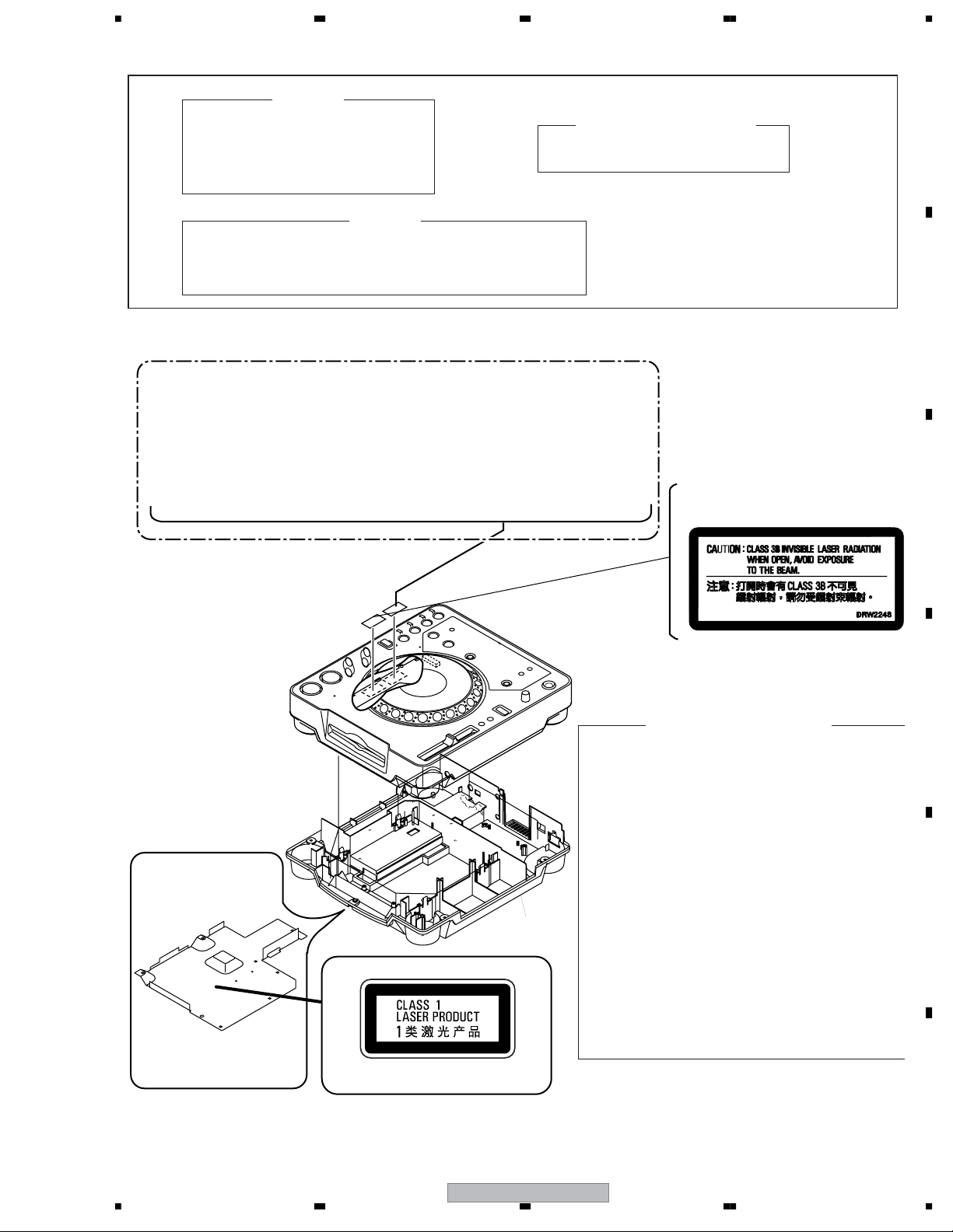
LABEL CHECK
MAXIMUM OUTPUT POWER: 5 mW
WAVELENGTH: 780 – 785 nm
WARNING !
CDJ-800MK2 WYXJ5 and KUCXJ : Types Only
LASER DIODE CHARACTERISTICS
for RLFXJ
(DRW2308)
A
B
C
Bottom Plate
Printed on the Bottom Plate
(DRW2248)
Additional Laser Caution
1. Laser Interlock Mechanism
The position of the switch (S1901) for detecting loading
completion is detected by the system microprocessor,
and the design prevents laser diode oscillation when
the switch is not in LPS1 terminal side (when the
mechanism is not clamped and LPS1 signal is
high level.)
Thus, the interlock will no longer function if the switch is
deliberately set to LPS1 terminal side. ( if LPS1 signal
is low level ).
In the test mode∗ the interlock mechanism will not
function. Laser diode oscillation will continue, if pin 41
of TC94A15FG (IC101) on the MAIN Assy is
connected to GND, or else the terminals of Q101 are
shorted to each other (fault condition).
2. When the cover is opened, close viewing of the
objective lens with the naked eye will cause exposure
to a Class 1 laser beam.
∗ : Refer to page 86.
D
E
56
CDJ-800MK2
F
3
7
8
1234
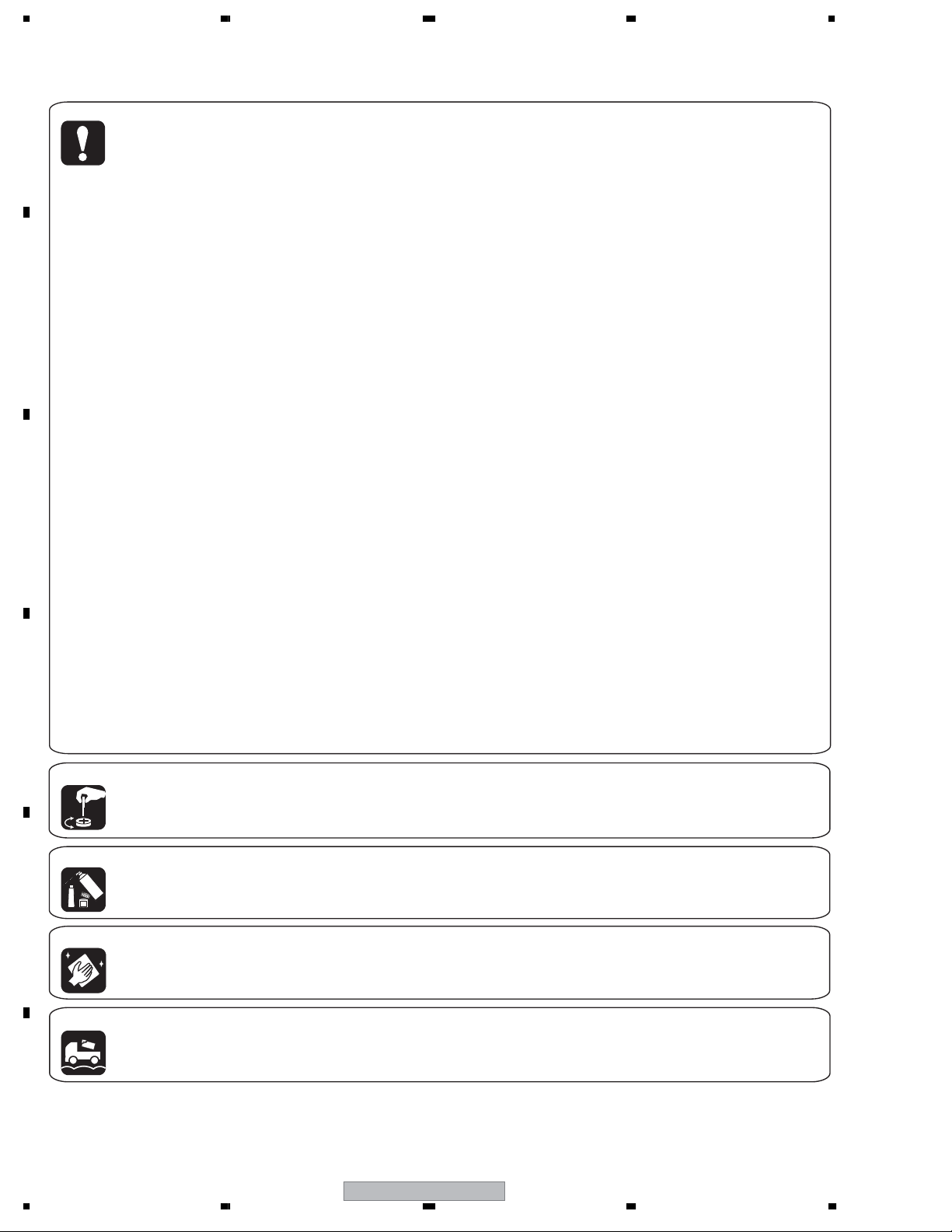
[Important Check Points for Good Servicing]
In this manual, procedures that must be performed during repairs are marked with the below symbol.
Please be sure to confirm and follow these procedures.
1. Product safety
A
Please conform to product regulations (such as safety and radiation regulations), and maintain a safe servicing environment by
following the safety instructions described in this manual.
1 Use specified parts for repair.
Use genuine parts. Be sure to use important parts for safety.
2 Do not perform modifications without proper instructions.
Please follow the specified safety methods when modification(addition/change of parts) is required due to interferences such as
radio/TV interference and foreign noise.
B
C
D
3 Make sure the soldering of repaired locations is properly performed.
When you solder while repairing, please be sure that there are no cold solder and other debris.
Soldering should be finished with the proper quantity. (Refer to the example)
4 Make sure the screws are tightly fastened.
Please be sure that all screws are fastened, and that there are no loose screws.
5 Make sure each connectors are correctly inserted.
Please be sure that all connectors are inserted, and that there are no imperfect insertion.
6 Make sure the wiring cables are set to their original state.
Please replace the wiring and cables to the original state after repairs.
In addition, be sure that there are no pinched wires, etc.
7 Make sure screws and soldering scraps do not remain inside the product.
Please check that neither solder debris nor screws remain inside the product.
8 There should be no semi-broken wires, scratches, melting, etc. on the coating of the power cord.
Damaged power cords may lead to fire accidents, so please be sure that there are no damages.
If you find a damaged power cord, please exchange it with a suitable one.
9 There should be no spark traces or similar marks on the power plug.
When spark traces or similar marks are found on the power supply plug, please check the connection and advise on secure
connections and suitable usage. Please exchange the power cord if necessary.
0 Safe environment should be secured during servicing.
When you perform repairs, please pay attention to static electricity, furniture, household articles, etc. in order to prevent injuries.
Please pay attention to your surroundings and repair safely.
2. Adjustments
To keep the original performance of the products, optimum adjustments and confirmation of characteristics within specification.
Adjustments should be performed in accordance with the procedures/instructions described in this manual.
3. Lubricants, Glues, and Replacement parts
Use grease and adhesives that are equal to the specified substance.
Make sure the proper amount is applied.
E
4. Cleaning
For parts that require cleaning, such as optical pickups, tape deck heads, lenses and mirrors used in projection monitors, proper
cleaning should be performed to restore their performances.
5. Shipping mode and Shipping screws
To protect products from damages or failures during transit, the shipping mode should be set or the shipping screws should be
installed before shipment. Please be sure to follow this method especially if it is specified in this manual.
F
4
1234
CDJ-800MK2

5678
CONTENTS
SAFETY INFORMATION......................................................................................................................................2
1. SPECIFICATIONS.............................................................................................................................................6
2. EXPLODED VIEWS AND PARTS LIST.............................................................................................................8
2.1 PACKING ....................................................................................................................................................8
2.2 EXTERIOR SECTION ..............................................................................................................................10
2.3 CONTROL PANEL SECTION ...................................................................................................................12
2.4 SLOT-IN MECHANISM SECTION ............................................................................................................14
3. BLOCK DIAGRAM AND SCHEMATIC DIAGRAM ..........................................................................................16
3.1 BLOCK DIAGRAM....................................................................................................................................16
3.2 BLOCK DIAGRAM (2) ..............................................................................................................................18
3.3 BLOCK DIAGRAM (Power).......................................................................................................................20
3.4 OVERALL WIRING DIAGRAM .................................................................................................................22
3.5 MAIN (1/3) and RLYB ASSYS ..................................................................................................................24
3.6 MAIN ASSY(2/3).......................................................................................................................................26
3.7 MAIN ASSY(3/3).......................................................................................................................................30
3.8 AC IN, TRNS, SECB and REGB ASSYS..................................................................................................32
3.9 DFLB, JACK and KSWB ASSYS..............................................................................................................34
3.10 JFLB, SLDB, SLMB and JOGB ASSYS .................................................................................................36
3.11 WAVEFORMS.........................................................................................................................................38
3.12 VOLTAGES..............................................................................................................................................45
4. PCB CONNECTION DIAGRAM ......................................................................................................................49
4.1 MAIN ASSY ..............................................................................................................................................50
4.2 RLYB ASSY ..............................................................................................................................................54
4.3 SECB ASSY .............................................................................................................................................56
4.4 TRNS ASSY..............................................................................................................................................60
4.5 AC IN ASSYS ...........................................................................................................................................62
4.6 DFLB ASSY..............................................................................................................................................64
4.7 REGB and JACK ASSYS..........................................................................................................................68
4.8 KSWB ASSY.............................................................................................................................................70
4.9 JFLB ASSY...............................................................................................................................................72
4.10 SLDB ASSY............................................................................................................................................76
4.11 SLMB and JOGB ASSYS .......................................................................................................................78
5. PCB PARTS LIST............................................................................................................................................80
6. ADJUSTMENT ................................................................................................................................................85
7. GENERAL INFORMATION .............................................................................................................................86
7.1 DIAGNOSIS..............................................................................................................................................86
7.1.1 SERVICE MODE................................................................................................................................86
7.1.2 RESET and CLOCK MAP ..................................................................................................................92
7.1.3 TROBLE SHOOTING .........................................................................................................................94
7.1.4 POWER ON SEQUENCE ................................................................................................................105
7.1.5 DISASSEMBLY ................................................................................................................................106
7.2 PARTS ....................................................................................................................................................114
7.2.1 IC......................................................................................................................................................114
8. PANEL FACILITIES .......................................................................................................................................140
A
B
C
D
56
CDJ-800MK2
E
F
5
7
8

1234
1. SPECIFICATIONS
Specifications
A
• KUCXJ type
1. General
System..............................Compact disc digital audio system
Power requirements.....................................AC 120 V, 60 Hz
Power consumption.......................................................20 W
Operating temperature.......... +5˚C to +35˚C (+41˚F to +95˚F)
Operating humidity...............................................5 % to 85 %
(There should be no condensation of moisture.)
Weight..............................................................4.0 kg (8.8 lb)
Dimensions..................... 305 (W) × 344.1 (D) × 106.5 (H)mm
B
12 (W) × 13 –9/16 (D) × 4 – 1/4 (H) in
• RLFXJ type
1. General
System........................... Compact disc digital audio system
Power requirements .... AC 110-120 V/220-240 V, 50/60 Hz
Power consumption ..................................................... 22 W
For Taiwan: 21 W
Operating temperature ..................................+5°C to +35°C
Operating humidity ........................................... 5 % to 85 %
(There should be no condensation of moisture.)
Weight ........................................................................4.0 kg
Dimensions .................. 305 (W) x 344.1 (D) x 106.5 (H) m
m
2. Audio section
Frequency response........................................4 Hz to 20 kHz
Signal-to-noise ratio..........................115 dB or more (JEITA)
Distortion.................................................... .0.006 % (JEITA)
3. Accessories
• Operating instructions........................................................1
• Power cord........................................................................1
• Audio cable....................................................................... 1
• Control cable..................................................................... 1
C
• Forced eject pin (housed in a groove in the bottom panel)... 1
• Limited warranty................................................................1
NOTE:
Specifications and design are subject to possible modification
with-out notice.
• WYXJ5 type
1. General
System.......................... Compact disc digital audio system
Power requirements .................... AC 220-240 V, 50/60 Hz
D
Power consumption ..................................................... 22 W
Operating temperature .................................. +5°C to +35°C
Operating humidity ............................................ 5 % to 85 %
(There should be no condensation of moisture.)
Weight ....................................................................... 4.0 kg
Dimensions ..................305 (W) x 344.1 (D) x 106.5 (H) mm
2. Audio section
Frequency response...................................... 4 Hz to 20 kHz
Signal-to-noise ratio ....................... 115 dB or more (JEITA)
Distortion ................................................... 0.006 % (JEITA)
3. Accessories
• Operating instructions ..................................................... 1
• Power cord ...................................................................... 1
• Audio cable ..................................................................... 1
• Control cable ................................................................... 1
• Forced eject pin (housed in a groove in the bottom panel)... 1
NOTE:
Specifications and design are subject to possible modification
with-out notice.
Voltage selector (RLFXJ type only)
• You can find the voltage selector switch on the bottom plate
of the unit.
The factory setting for the voltage selector is 220 – 240 V.
Please set it to the correct voltage for your country or region.
• For Taiwan, please set to 110 – 120 V before using.
Before changing the voltage, disconnect the AC power cord.
Use a medium size screwdriver to change the voltage
selector switch.
220-240V
2. Audio section
Frequency response...................................... 4 Hz to 20 kHz
Signal-to-noise ratio ....................... 115 dB or more (JEITA)
Distortion ................................................... 0.006 % (JEITA)
E
3. Accessories
• Operating instructions ..................................................... 1
• Power cord ...................................................................... 1
• Audio cable ..................................................................... 1
• Control cable ................................................................... 1
• Forced eject pin (housed in a groove in the bottom panel)... 1
NOTE:
Specifications and design are subject to possible modification
with-out notice.
F
6
1234
110-120V
CDJ-800MK2
5678
A
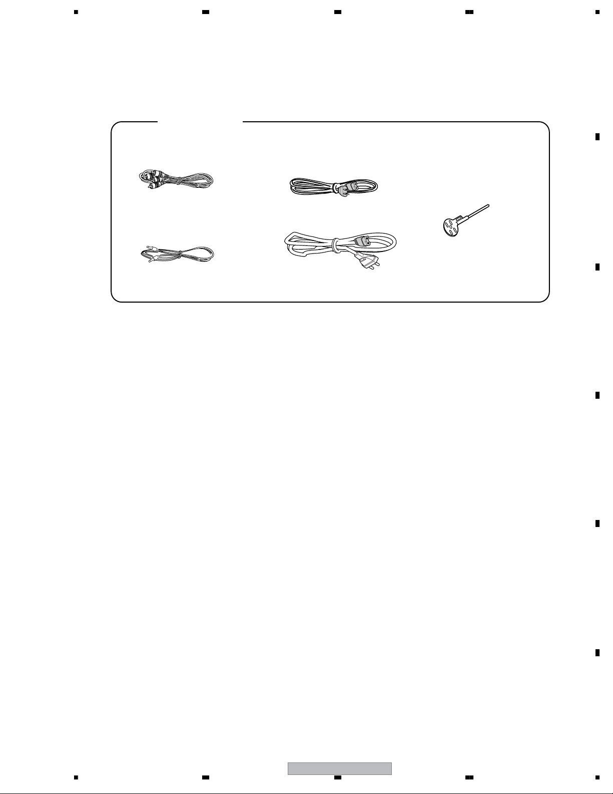
Accessories
Audio Cable
(VDE1064) L=1.5m
Control Cord
(XDE3063) L=1 m
Power Cord
(ADG7021 : KUCXJ)
(ADG7097 : RLFXJ)
(ADG1154 : WYXJ,RLFXJ)
Forced Fject Pin
(housed in a groove in
the bottom panel)
(DEX1008)
B
C
D
E
F
56
CDJ-800MK2
7
7
8
1234
2. EXPLODED VIEWS AND PARTS LIST
NOTES:
A
Parts marked by "NSP" are generally unavailable because they are not in our Master Spare Parts List.
The mark found on some component parts indicates the importance of the safety factor of the part.
Therefore, when replacing, be sure to use parts of identical designation.
Screws adjacent to mark on product are used for disassembly.
For the applying amount of lubricants or glue, follow the instructions in this manual.
(In the case of no amount instructions, apply as you think it appropriate.)
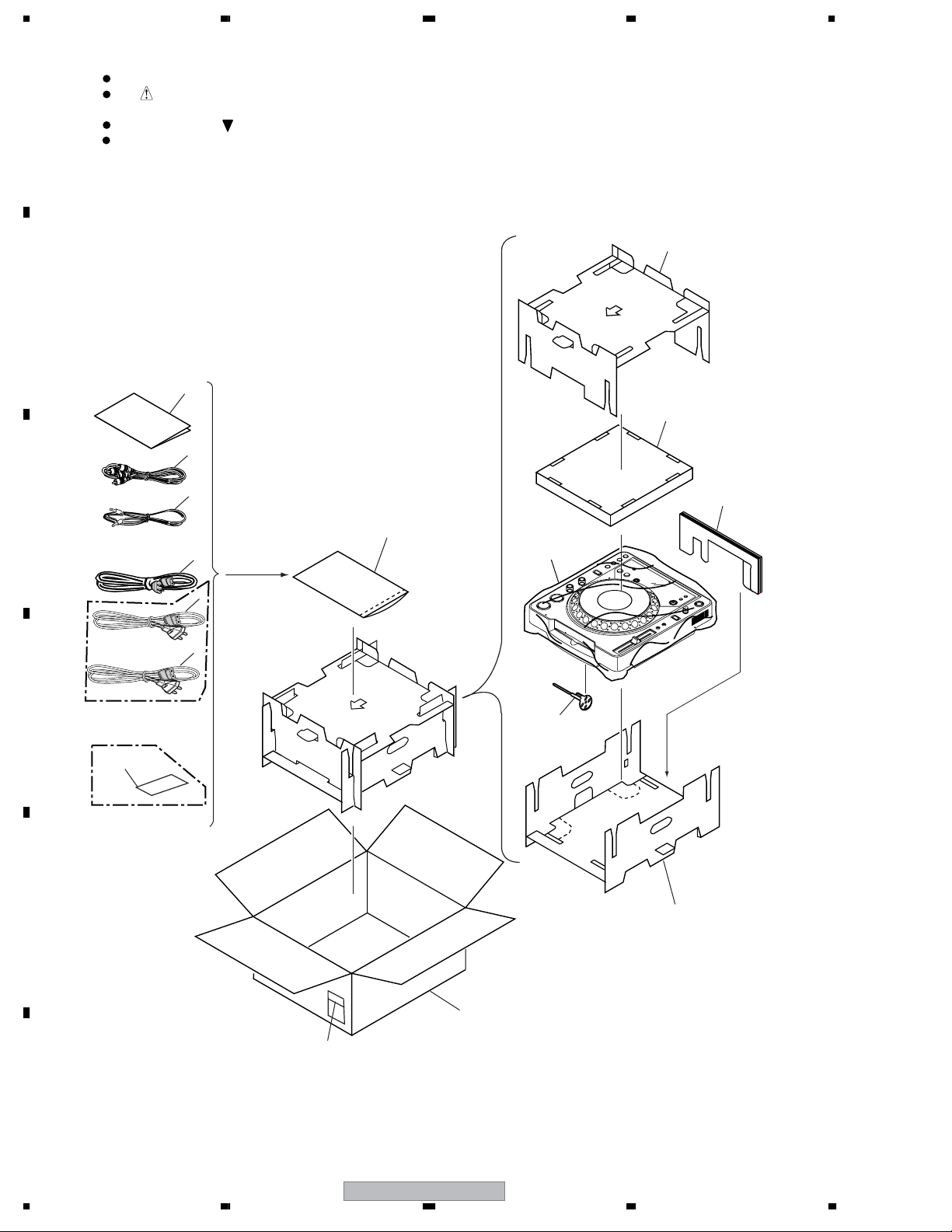
2.1 PACKING
B
C
KUCXJ & RLFXJ
types only
6
4
7
3
2
5
1
9
8
1
1
D
E
WYXJ & RLFXJ
type only
13
KUCXJ type
only
10
11
12
14
F
8
1234
CDJ-800MK2
>
>
>
5678
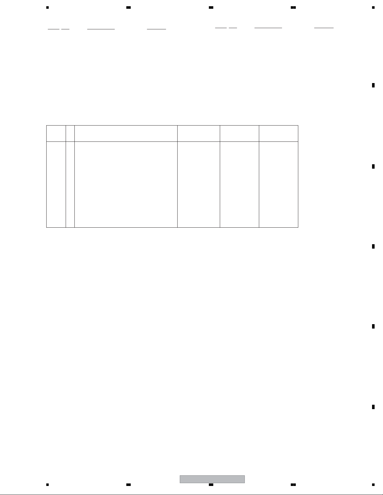
PACKING parts List
No. Description Part No.
No. Description Part No.
Mark
1AC Power Cord See Contrast table(2)
2 Control Cord XDE3063
3Audio Cord VDE1064
4 Operating Instructions See Contrast table(2)
NSP 5 Polyethylene Bag AHG7117
6Pad B DHA1556
7Pad C DHA1557
8Pad D DHA1558
Mark
9 Sheet RHX1006
10 Push Rod DEX1008
11 Pad A DHA1555
12 Packing Case See Contrast table(2)
NSP 13 Warranty Card See Contrast table(2)
NSP 14 Label See Contrast table(2)
(2) CONTRAST TABLE
CDJ-800MK2/KUCXJ, /WYXJ5 and RLFXJ types are constructed the same except for the following:
Mark No. Symbol and Description
1AC Power Cord ADG7021 ADG1154 ADG1154
1AC Power Cord Not used Not used ADG7097
4 Operating Instructions (English)(KUCXJ) DRB1401 Not used Not used
4 Operating Instructions (WYXJ5)(English, Not used DRB1400 Not used
French, German, Italian, Dutch, Spanish)
CDJ-800MK2/
KUCXJ
CDJ-800MK2/
WYXJ5
CDJ-800MK2/
RLFXJ
A
B
4 Operating Instructions (RLFXJ) Not used Not used DRB1402
(English, Spanish, Chinese)
12 Packing Case DHG2595 DHG2594 DHG2596
NSP 13 Warranty Card ARY7043 Not used Not used
NSP 14 Label DRW2311 VRW1629 VRW1629
C
D
E
56
CDJ-800MK2
F
9
7
8
1234
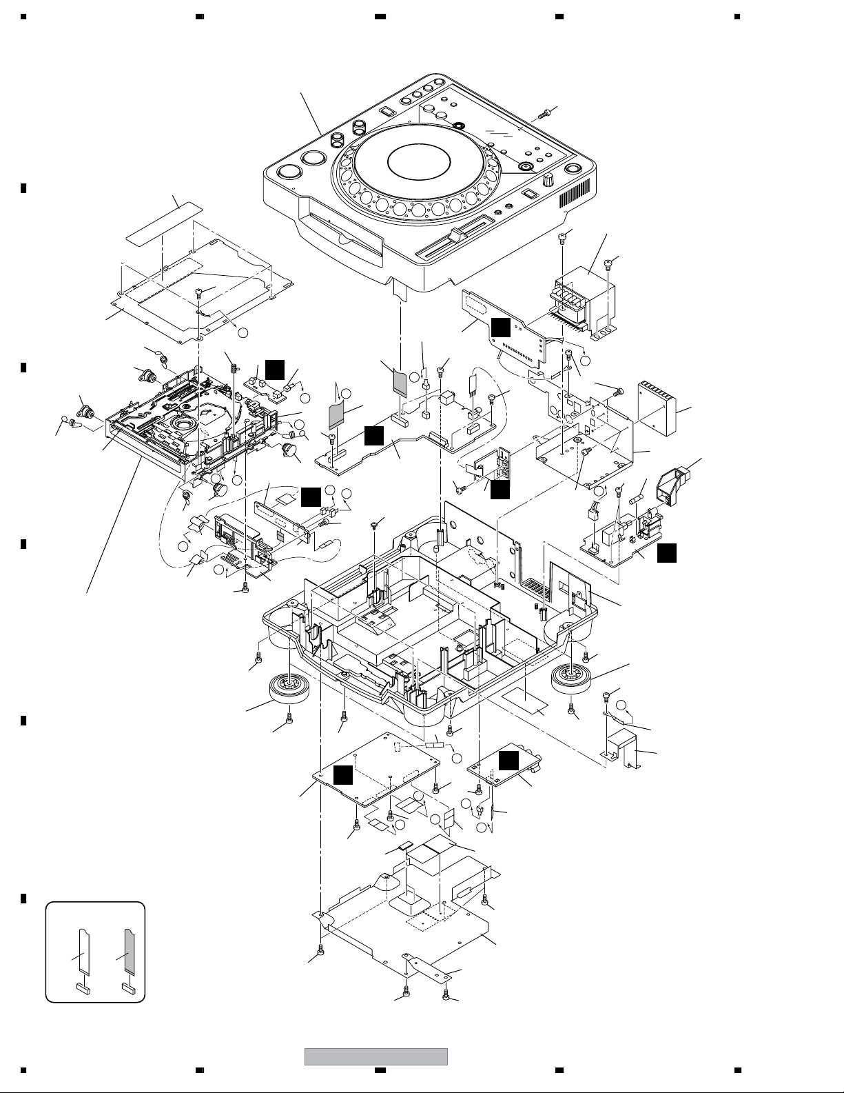
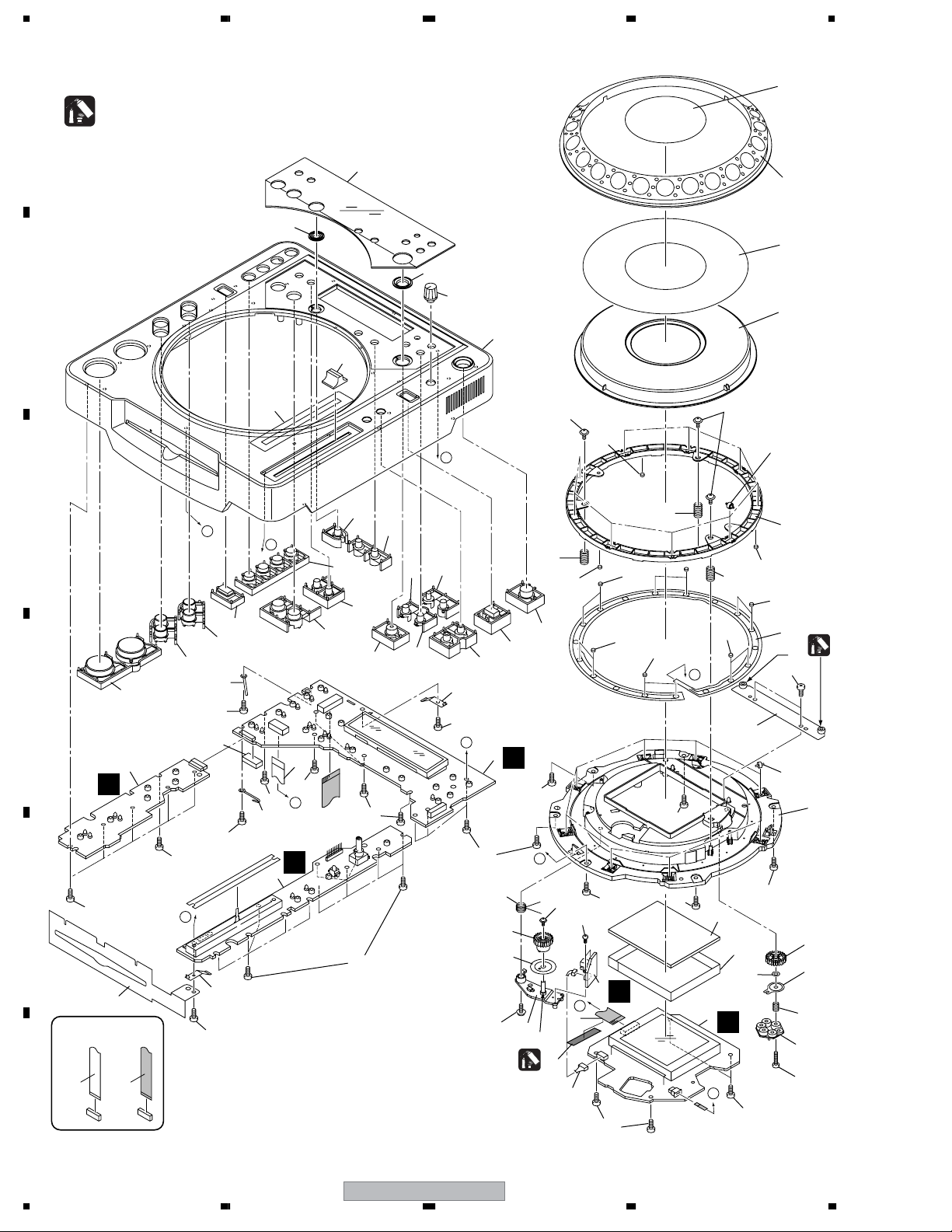
2.2 EXTERIOR SECTION
Refer to
"2.3 CONTROL PANEL SECTION".
A
38
42
43
17
43
B
35
33
31
31x4
33x4
C
D
E
34
Refer to
"2.4 SLOT-IN MECHANISM SECTION".
33
G
15
31
12
F
44
A
32
6
18
M
B
37
D
44
33
31
9-(b)
E
B
7
E
44
36
44
30
46x4
14
C
13
C
B
D
44
44
A
1
44
22
45
19
44
H
4
F
44
41
11
44
C
G
3
J
44
12
44
H
J
23
D
I
39
41
46
41
24
28
10
44
I
E
2
29
44
30
44
A
16
25
21
44
F
5
I
8
11
F
10
NON-CONTACT
CONTACT SIDE
SIDE
1234
44
44
CDJ-800MK2
40
26
27
44
>
>
>
>
>
>
>
>
>
5678
EXTERIOR SECTION parts List
No. Description Part No.
Mark
1 MAIN Assy DWG1622
2AC IN Assy See Contrast table(2)
3 TRNS Assy See Contrast table(2)
4 SECB Assy DWR1309
5 REGB Assy DWR1310
6 SLMB Assy DWS1388
7RLYB Assy DWX2602
8JACK Assy DWG1626
9• • • •
10 Fuse See Contrast table(2)
11 FFC (9p) DDD1311
12 FFC (32p) DDD1312
13 FFC (25p) DDD1313
14 FFC (17p) DDD1314
15 FFC (24p) DDD1315
NSP 16 Earth Lead DE010VF0
17 Power Transfomer See Contrast table(2)
18 Connector Assy PF03PP-B05
19 Connector Assy PF03PP-C12
20 • • • •
21 Power Knob DAC2073
NSP 22 Silicon Lubber D5 L DEB1456
23 Bottom Cushion S4 DEC2506
24 Heat Sink DNG1102
No. Description Part No.
Mark
25 Earth Plate DNH2532
26 Bottom Plate See Contrast table(2)
27 Bottom Earth Plate DNH2694
28 Trans Plate DNH2733
NSP 29 Chassis See Contrast table(2)
30 Insulator Assembly DXA2069
31 Damper CNV6011
32 Earth Spring DBH1398
33 Float Spring (G5) DBH1494
34 Front Sheet DED1132
35 Mecha Plate DNH2642
36 PCB Holder DNK4524
37 Float Base 04 Assy DXB1838
38 Laser Caution See Contrast table(2)
NSP 39 Serial Label (UPC) See Contrast table(2)
40 Screw BBT30P060FCC
41 Screw BBZ30P060FTC
42 Screw BBZ30P100FTC
43 Screw BBZ40P060FTC
44 Screw BPZ30P080FTB
45 DM Screw (FTC) DBA1260
46 Screw IPZ30P100FTC
A
B
C
(2) CONTRAST TABLE
CDJ-800MK2/KUCXJ, /WYXJ5 and RLFXJ types are constructed the same except for the following:
Mark No. Symbol and Description
2AC IN ASSY DWR1430 DWR1429 DWR1432
3 TRANS ASSY DWR1371 DWR1371 DWR1428
10 Fuse (T1.6A) AEK7075 Not used Not used
10 Fuse (800MA) Not used REK1021 REK1021
17 Power Transfomer DTT1204 DTT1203 DTT1203
26 Bottom Plate DNK2689 DNK2689 DNK2691
29 Chassis DNK4518 DNK4517 DNK4519
38 Laser Caution DRW2308 DRW2308 DRW2248
NSP 39 Serial Label DRW2311 VRW1629 VRW1629
CDJ-800MK2/
KUCXJ
CDJ-800MK2/
WYXJ5
CDJ-800MK2/
RLFXJ
D
E
56
CDJ-800MK2
F
11
7
8
1234
2.3 CONTROL PANEL SECTION
8
A
B
C
D
E
F
Grease: GYA1001( ZLB-PN397B)
1
*
37
2
H
58
49
NON-CONTACT
SIDE
CONTACT SIDE
38-(c)
58
B
C
38-(b)
60
58
50
58
48-1
58
45
60
46
B
58
47
21
51
9
52
31
53
41
5656x3
17
A
40
43
23
14
33
G
58
22
10
38-(a)
C
1
*
59
56
17
58
54x2
5
D
6
7
58
35
42
34
36
6
58
D
J
4
58
58
39
39
44
48-2
58
A
32
1
58
12
57
L
13
13
13
10
58
58
10x3
13
E
15
16
3
K
E
29
61
58
28x9
17x3
58
26
18
13x12
27
*
58
30x8
1
20
25
24
11
19
55
12
CDJ-800MK2
1234

5678
CONTROL PANEL SECTION parts List
No. Description Part No.
Mark
1 DFLB Assy DWG1623
2 KSWB Assy DWS1386
3 JFLB Assy DWG1624
4 SLDB Assy DWS1387
5 JOGB Assy DWG1625
6 FFC DDD1220
7 Connector Assy PF04PP-B07
8 Jog Panel (PMMA) DAH2182
9 Jog Plate DAH2438
10 SW spring 25 DBH1514
11 Gear spring 200 DBH1525
12 ARM Sprimg DBH1566
13 SW Cushion HH48/2 DEC2538
14 Encorder Plate DEC2889
15 Protector Sheet DEC2945
16 FL Sheet DEC2946
17 Ring Cushion L24/2.0 DEC2958
18 SW Ring DNK4070
19 Adjust Plate DNK4178
20 Jog Holder DNK4545
21 Jog B DNK4557
22 Gear ARM DNK4559
23 Gear DNK4560
24 Smoother DNK4561
25 Load Gear A DNK4562
No. Description Part No.
Mark
50 FFC Guard DEC2586
51 Reloop Guard DNK4057
52 Q R Guard DNK4058
53 Control Panel DNK4525
54 Screw BPZ20P060FTC
55 Screw BPZ20P100FTC
56 Screw (FE) DBA1265
57 Screw IPZ30P100FTC
58 Screw BPZ30P080FTB
59 Ecsane Tape (10x50 ) DEC2988
60 Cord Clamper RNH-184-0
61 Washer WA42D080D050
A
B
C
26 Jog A DNK4586
27 Sheet SW DSX1065
28 Roller A Assy DXB1825
29 Jog Stay Assy DXB1876
30 Roller B Assy DXB1877
31 Rotary Knob C DAA1194
32 TEMPO Knob DAC2061
33 VINYL Knob DAC2063
34 LOOP Knob DAC2066
35 Auto Beat Loop Knob DAC2069
36 Quick Return Knob DAC2070
37 PLAY Knob DAC2286
38 Set Knob (Eject) DAC2287
39 CALL Knob DAC2289
40 RELOOP Knob DAC2291
41 Slide Knob DAC2292
42 TEXT/A.CUE Knob DAC2294
43 Folder Search Knob DAC2298
44 DEL/MEMO Knob DAC2299
45 Reverse Knob DAC2364
46 Slide Sheet (gray) DAH2374
47 Display Panel DAH2418
48 Earth Plate (CU) DBK1224
49 Vessel Sheet DEC2495
D
E
F
56
CDJ-800MK2
13
7
8
1234
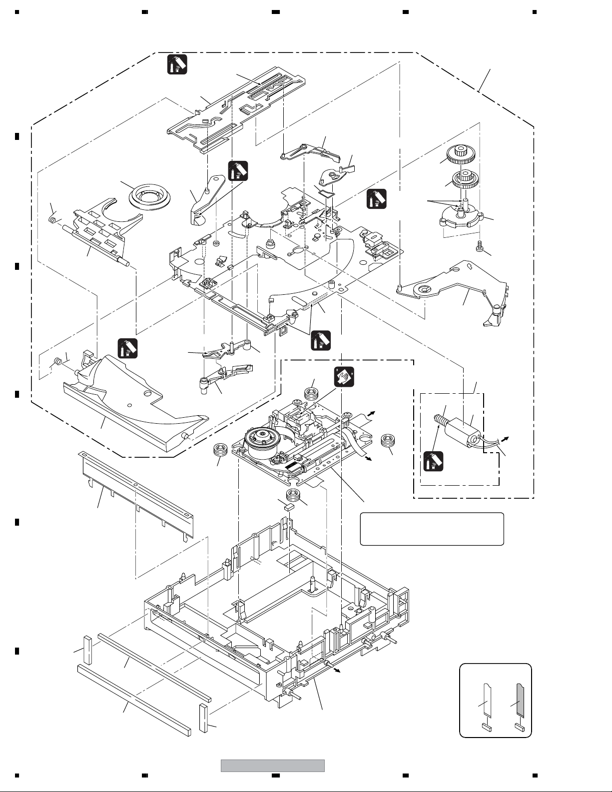
2.4 SLOT-IN MECHANISM SECTION
Grease
A
GYA1001
1
(ZLB-PN397B)
11
20
21
Dyefree
23
B
7
10
GEM1036
(ZLX-ME413A)
9
Grease
GYA1001
(ZLB-PN397B)
13
19
C
8
Dyefree
GEM1036
15
(ZLX-ME413A)
16
Dyefree
GEM1036 (ZLX-ME413A)
25
Cleaning liquid : GEM1004
Cleaning paper : GED-008
RLYB CN12
To
(Pickup)
12
18
17
22
24
14
3
4
5
To
RLYB CN16
(Loading Motor)
D
25
RLYB CN14
(Stepping Motor)
25
To
Grease
GYA1001
(ZLB-PN397B)
6
27
31
25
2
Note:
The TM. Assy 03-S is supplied only in
assembly form, not as a single part.
E
30
29
F
28
30
26
To MAIN CN102
(Spindle Motor)
NON-CONTACT
SIDE
CONTACT SIDE
14
CDJ-800MK2
1234

5678
SLOT-IN MECHANISM SECTION parts List
No. Description Part No.
Mark
NSP 1 Slot-in Mecha SV Assy DXA2005
2 TM. Assy 03-S VXX3125
3 Loading Motor Assy-S DXX2510
NSP 4 Worm Gear DNK3910
NSP 5 DC Motor S (ROHS) DXM1230
6 Connector Assy PF02PY-B22
7 Clamp Spring DBH1374
8 Guide Spring DBH1375
9 SW Lever Spacer SV DEC2831
10 Loading Lever DNK3406
A
11 Main Cam DNK3407
12 Disc Guide DNK3478
13 Clamp Arm DNK3576
14 Eject Lever DNK3684
15 Lever AP DNK3835
16 Lever BP DNK3836
17 Loading Gear DNK3911
18 Drive Gear DNK3912
19 Loading Base SV DNK4369
20 SW Lever SV1 DNK4370
21 SW Lever SV2 DNK4371
22 Gear Holder SV DNK4372
23 Clamper 04 Assy DXB1859
24 Screw BPZ20P060FTC
25 Floating Rubber (SI) VEB1351
26 Float Base 04 Assy DXB1838
27 Spacer POR (T3) DEB1566
28 Vessel Cushion A DEC2852
29 Vessel Cushion B DEC2853
30 Vessel Cushion C DEC2854
31 Front Sheet DED1132
B
C
D
56
CDJ-800MK2
E
F
15
7
8
1234
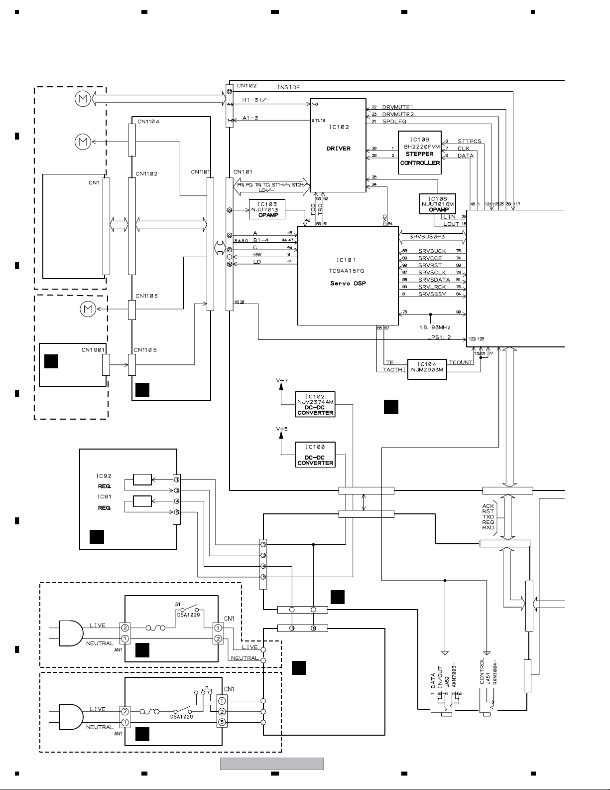
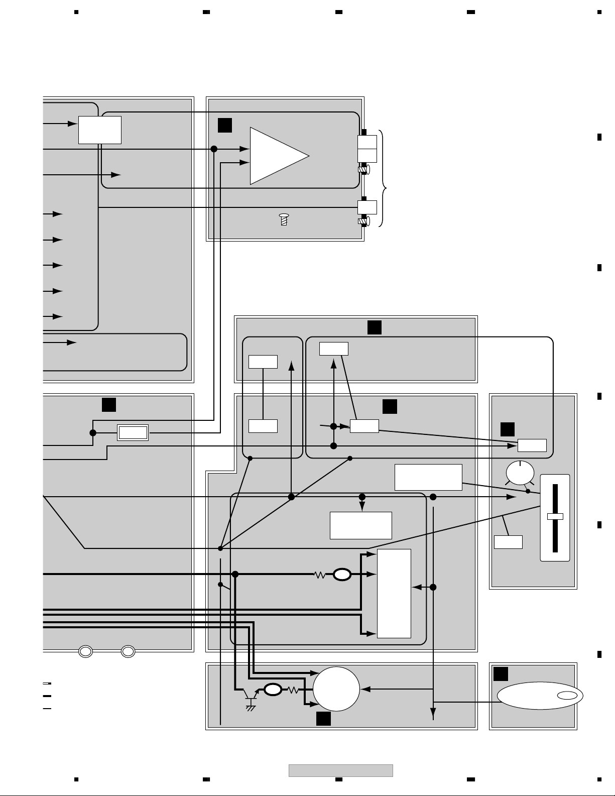
3. BLOCK DIAGRAM AND SCHEMATIC DIAGRAM
3.1 BLOCK DIAGRAM
A
TM. ASSY 03-S (VXX3125)
SPINDLE
MOTOR 04
B
C
Loading MOTOR
ASSY-S
(DXX2510)
STEPPING
MOTOR 04
PICKUP ASSY
M
SLMB ASSY
SLOT-IN
MECHANISM SV
ASSY
RLYB ASSY
B
M63018FP
COMPARATOR
MAIN ASSY
A
D
J91
BA008C0WCP
BA008C0WCP
REGB ASSY
F
E
F
For KUCXJ, WYXJ5
For RLFXJ
ACIN ASSY
E
ACIN ASSY
E
S2
S1
BROWN
VIOLET
BLUE
V+10B
V+7A
V+6B
V+3D
CN52
CN51
CN22
J2
J3
NJM2885DL1
CN301
CN53
11 9
TRNS ASSY
D
SECB ASSY
C
CN301
CN53
CN56
CN50
16
CDJ-800MK2
1234
5678
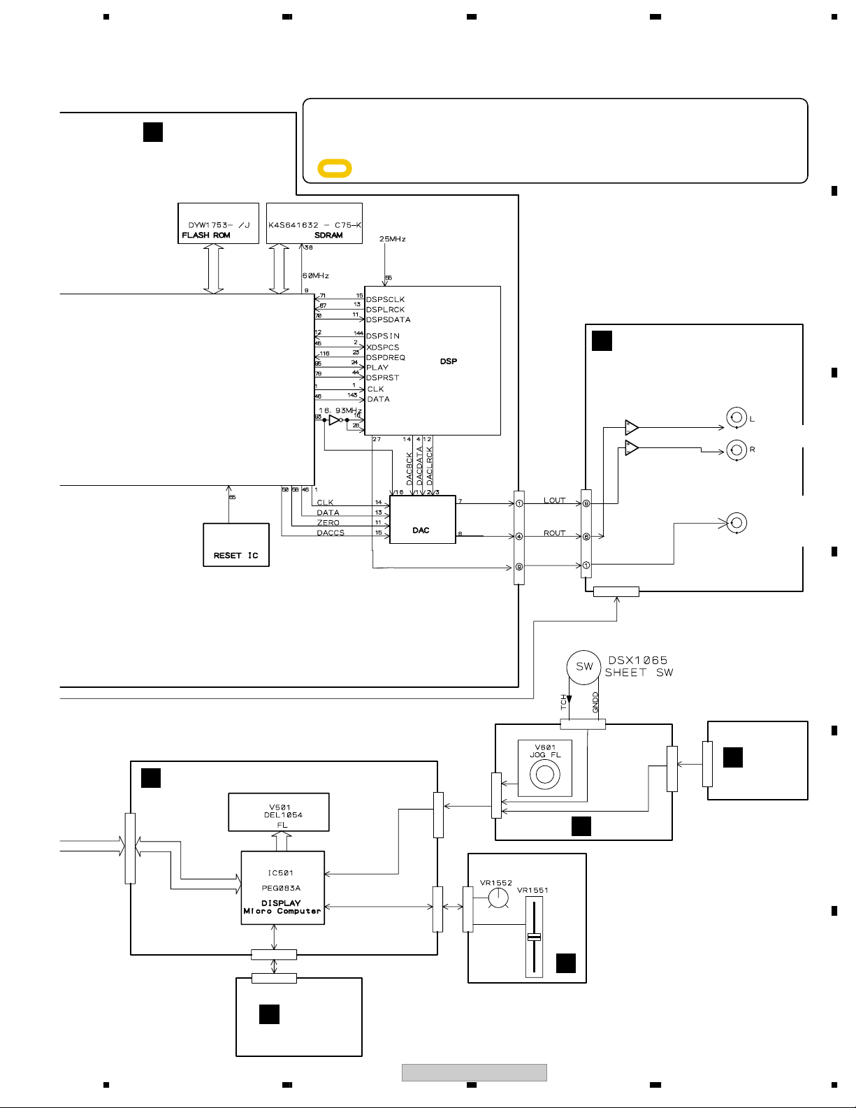
MAIN ASSY
A
IC300
8 Mbit 64 Mbit
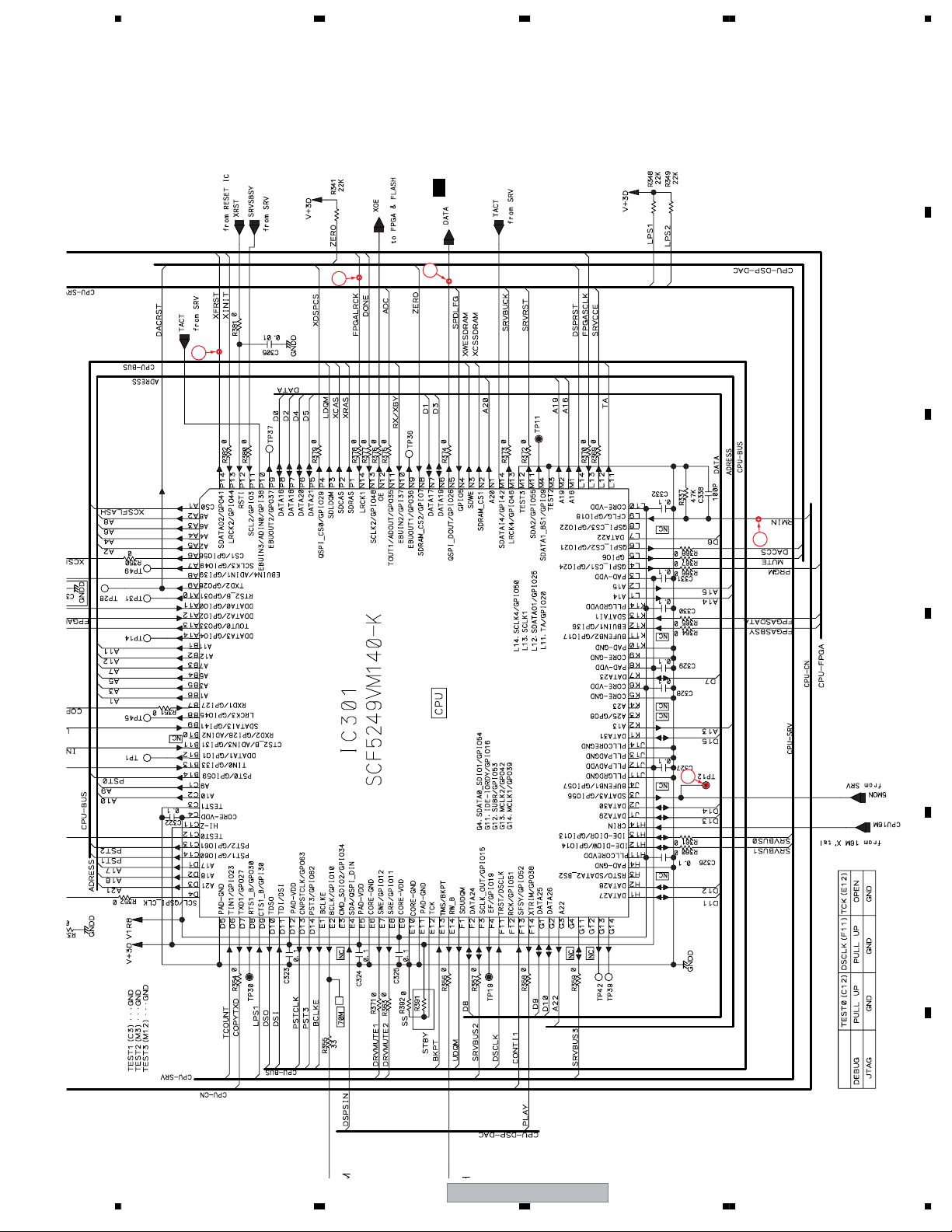
IC301
SCF5249VM140-K
MPU
IC304
BU4230G
÷
When ordering service parts, be sure to refer to "EXPLODED VIEWS and PARTS LIST" or
"PCB PARTS LIST".
÷
The > mark found on some component parts indicates the importance of the safety factor
of the part. Therefore, when replacing, be sure to use parts of identical designation.
÷
IC303
: The power supply is shown with the marked box.
KU
IC701
DSPC56371AF180-K
CN701
IC702
PE8001A
19
4
9
CN801
JACK ASSY
I
IC801
OP AMP
6
1
CN802
JA801
DKB1053
JA802
PKB1033
DIGITAL OUT
A
B
AUDIO OUT
C
DFLB ASSY
G
CN501
CN502
CN1502
H
KSWB ASSY
CN500
CN503
CN600
CN1503
CN602
CN601
K
JFLB ASSY
SLDB ASSY
J
D
CN1601
L
JOGB ASSY
E
F
56
CDJ-800MK2
17
7
8
R
S
R
C
C
R
1234
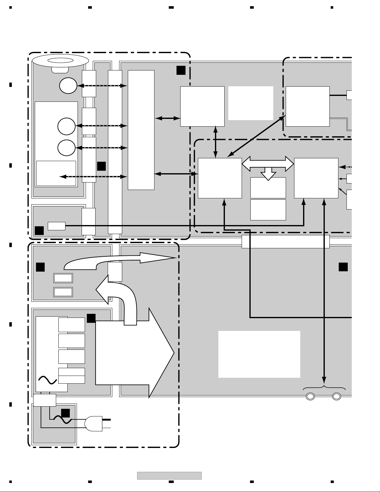
3.2 BLOCK DIAGRAM (2)
• Blick diagra Map
A
CD DRIVE BLOCK
AUDIO BLOCK
MAIN ASSY
A
Loading
TRAVERS
B
SLED
Spindle
Pickup ASSY
MECHA
M
M
M
KP 2PIN
IC101
SERVO DSP
DWX2602
KP 4PINFFC17PINKP 3PIN
IC102 DRIVER
B
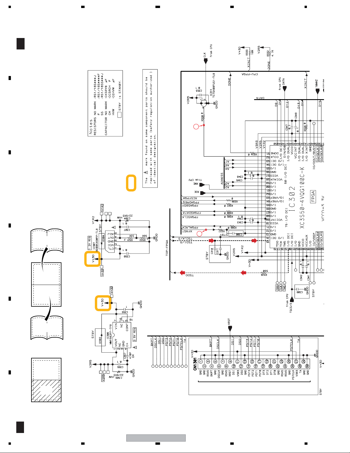
IC302
FPGA
(50000GATE)
DRIVE ASSY
C
SLMB ASSY
DWS1388
SW
FFC 32PIN
RLYB ASSY
DWG1622
SDRAM
(64 Mbit)
FLASH
(8 Mbit)
IC701
AUDIO
DSP
IC301
MPU
(140MHz)
I
1
M
FFC 25PIN
REGB ASSY
DWR1310
SE
DW
F
+3.3V
D
+7V
IC91
IC92
6PIN
C
TRNS ASSY
V+6
UnReg
V+10
UnReg
Vload
E
3PIN
+32V
Transformer
FLAC_D
FLAC_J
D
POWER
SUPPLY
DATA Cntrol
E
CDJ-800MK2 has two MPU, MPU (MAIN), DISPLAY-MPU (DFLB).
One controls CORE BLOCK, Another is Top panel about DISPLAY, LED, VOLUME,
ACIN ASSY
F
POWER BLOCK
RESET IC and X'TAL have on the MAIN ASSY too.
It has two MEMORY. One 64MB sized SDRAM, Another is 8MB sized FLASH MEMO
About POWER BLOCK, Please refer to POWER DELIVERY MAP.
18
CDJ-800MK2
1234
(
O BLOCK
IC701
UDIO
DSP
IC301
MPU
(140MHz)
5678
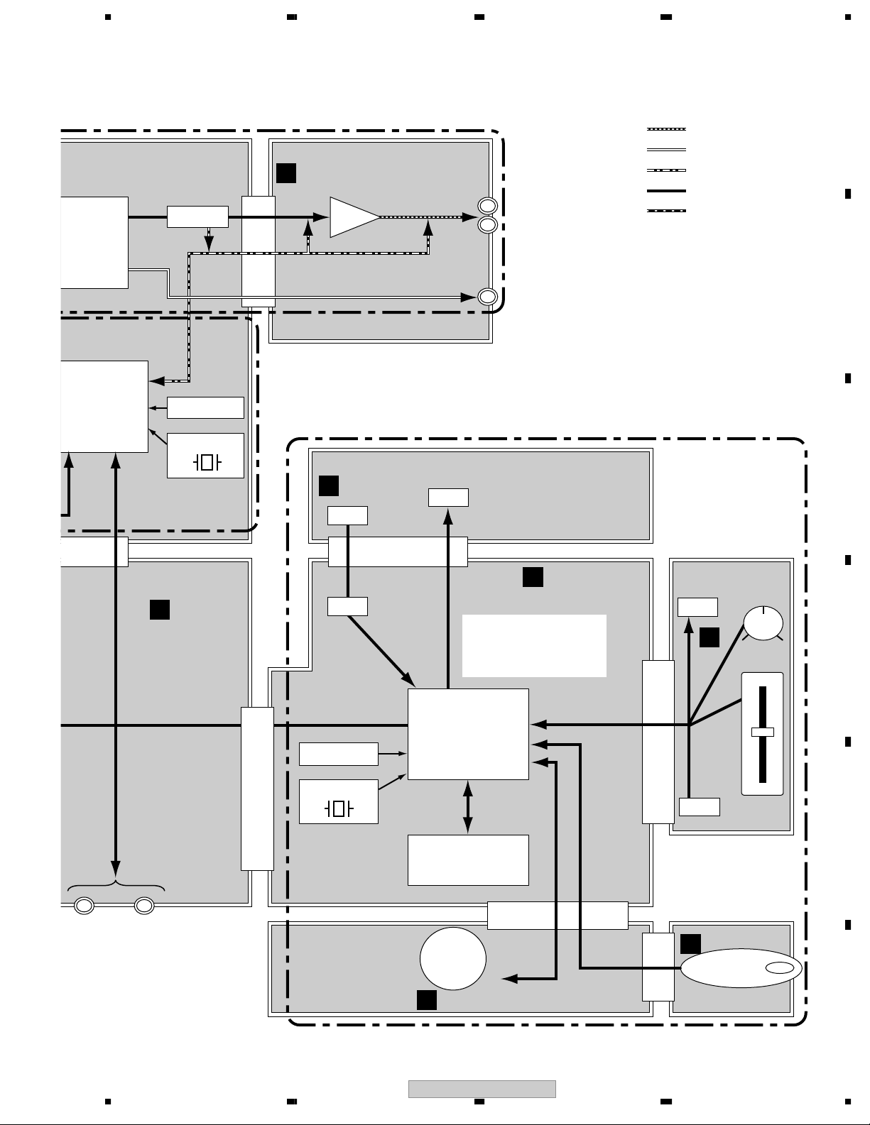
A
AUDIO OUT LINE
DIGITAL OUT LINE
AUDIO MUTE LINE
CONTROL LINE
DRIVE CONTROL
B
IC702
DAC
ZERO
DETECT
RESET IC
JACK ASSY
DWG1626
I
IC801 OPAMP
MUTE MUTE
FFC 9PIN
AUDIO OUT
(L/R)
Digital OUT
PANEl BLOCK
16.934MHz
KSWB ASSY
CORE BLOCK
H
SW
DWS1386
LED
C
B to B 8PIN
SECB ASSY
DWR1309
C
RESET IC
16.00MHz
FFC 17PIN
SW
IC501
DISPLAY
MPU
(MASK)
V501
DATA FL
DFLB ASSY
G
DWG1623
SLDB ASSY
SLDB ASSY
DWS1387-A/J
DWS1387
LED
J
SW
B to B 11PIN
Vol
D
VYNIL
SLIDER
E
JOGB ASSY
DATA Cntrol
R to R 13PIN
JOG
DFLB).
ISPLAY, LED, VOLUME, SW, JOG, etc.
8MB sized FLASH MEMORY.
MAP.
FL
K
JFLB ASSY
DWG1624
DWG1625
L
KP 4PIN
Rotation Detect
F
56
CDJ-800MK2
19
7
8
0
C506
)
GNDA
GNDD
GNDD
GNDD
1234
3.3 BLOCK DIAGRAM (Power)
• Power Delivery Map
A
Loading
M
GNDMGNDM
Motor Drive
GNDMGNDM
MAIN ASSY
A
DWG1622
5A
IC704 <0.3A
DAC
TRAVERS
MECHA
B
Spindle
SLED
M
M
Pickup ASSY
C
DWX2602
Stby
RLYB ASSY
GNDSGNDS
B
SLMB ASSY
DWS1388 ServoDSP 83
GNDDGNDD
M
V+7M V+8A V+5P V+6B
REGB ASSY
DWR1310
F
D
TRNS ASSY
E
Transformer
+3.3D
+7A
V+6
UnReg
V+10
UnReg
Vload
+32V
FLAC_D
FLAC_J
IC91 <
<1.0A
IC92
<1.0A
D
IC23,24IC23,24
<3.5A<3.5A
IC21,22IC21,22
<5.0A<5.0A
IC25IC25
<630mA<630mA
ICP
<10 A
IC56
<800mA IC53
<1.5A IC54
GNDMGNDM
<200mA
IC58 IC59
GNDDGNDD
+8A
<0.8A IC61
IC57 <1.0A
+5P
<1A IC50
Q53
+1.2D
1.25D
1.8D
2.5D
V+3D
IC100 <x.x0.6A LD 80
GNDDGNDD
ICP <200mA IC60
<200mA
IC307 <0.6A FPGA (SPARTAN3)FPGA (SPARTAN3)
IC703 <0.6A DSP
IC305 <0.5A CPU (AMADEUS)CPU (AMADEUS)
IC306 <0.5A FPGA (SPARTAN3)FPGA (SPARTAN3)
CUP 21 FPGA 60 DSP 5CUP 21 FPGA 60 DSP 5
SDRAM 22 FLASH 5SDRAM 22 FLASH 5
3.3S
GNDSGNDS
C52
C
MUTE
GNDSGNDS
SECB
DWR13
-7
F
20
E
ACIN ASSY
1234
3.3V
3.3V
CDJ-800MK2
Regurator supporting Current Shutdown
IC Protect
ICP
Pori SW
FUSE
MAX SPEC
A
DATA Cntrol
15W POINT
Before REG-IC
GND
Screw (Chasis GND
GNDSGNDS
5678
A
<0.3A
6A FPGA (SPARTAN3)FPGA (SPARTAN3)
6A DSP
5A CPU (AMADEUS)CPU (AMADEUS)
5A FPGA (SPARTAN3)FPGA (SPARTAN3)
DAC
CUP 21 FPGA 60 DSP 5CUP 21 FPGA 60 DSP 5
SDRAM 22 FLASH 5SDRAM 22 FLASH 5
ServoDSP 83
LD 80
SECB ASSY
C
DWR1309
MUTE
GNDSGNDS
-7
<1.0A IC51
JACK ASSY
I
GNDAGNDA
GNDDGNDD
DWG1626-A/J
OP
AMP
GNDDGNDD
Stby
KSWB ASSY
SW
V+5P V+7
GNDADGNDAD
SW
DWS1386
LED
L
R
D
LED
H
GNDDGNDD
Jack
DFLB ASSY
G
DWG1623
EarthPlate
ChasisGND
SLDB ASSY
SLDB ASSY
DWS1387
GNDDGNDDGNDD
J
GNDFGNDF
GNDFGNDF
Vol
LED
VYNIL
B
C
D
DATA Cntrol
15W POINT
Before REG-IC
GND
Screw (Chasis GND)
56
C506 C506
GNDDGNDD
DISPLAY
MPU
DATA FL
GNDDGNDD
GNDDGNDD
JOG
FL
<200mA IC603
Q604 DWG1624
K
JFLB ASSY
CDJ-800MK2
7
GNDADGNDAD
V+5P
SW
SLIDER
JOGB ASSY
DWG1625
L
Rotation Detect
8
E
F
21
1234
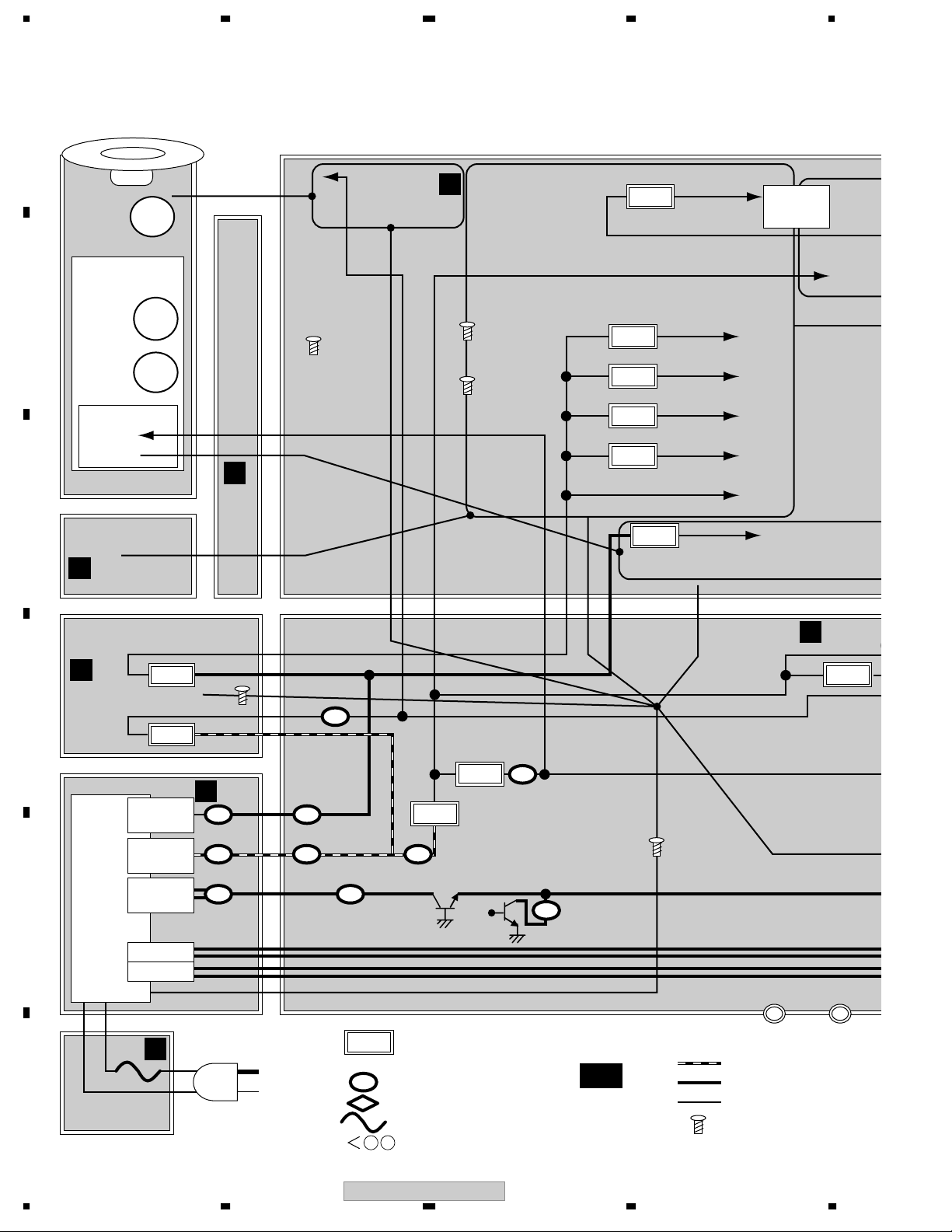
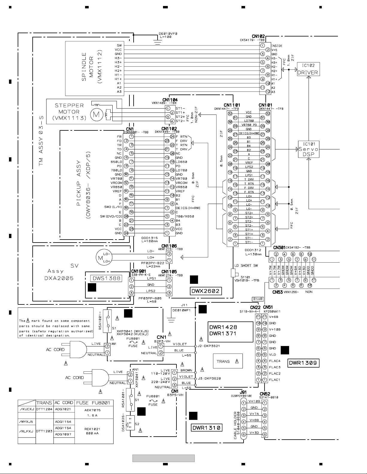
3.4 OVERALL WIRING DIAGRAM
A
B
(VXX3125)
CD PLAYER UNIT
C
D
E
(Loading Motor Assy-S)
DXX2510
SLOT-IN
SLMB ASSY
M
ACIN ASSY
E
DWR1429(WYXJ5)
DWR1430(KUCXJ)
RLYB ASSY
B
D
TRNS ASSY
(KUCXJ, WYXJ5)
(RLFXJ)
SECB ASSY
C
ACIN ASSY
E
DWR1432(RLFXJ)
F
22
1234
CDJ-800MK2
REGB ASSY
F
5678
MAIN ASSY
A
A A( 1/3 – 3/3)
JACK ASSY
I
A
B
C
DFLB ASSY
G
JFLB ASSY
K
JOGB ASSY
L
D
SLDB ASSY
J
E
KSWB ASSY
H
56
CDJ-800MK2
F
23
7
8
1234
3.5 MAIN (1/3) and RLYB ASSYS
A
A 1/3
MAIN ASSY (DWG1622)
20
B
C
17
(RF)
(RF)
(RF)
(RF)
(TS)
(F)
(TS)
8
(RF)
(RF)
(RF)
(RF)
(RF)
(RF)
(TD)
(TD)
(F)
(F)
(F)
1
2
13
(F)
(TS)
28
12
14
9
(TS)
11
(F)
D
5
(S)
(S)
10
E
to SPINDLE MOTOR
16
15
(S)
(S)
(S)
(S)
(S)
(S)
(TS)
(F)
37
38
(F)
(TS)
(TS)
(F)
(F)
(TS)
F
A 1/3
24
CDJ-800MK2
1234
(RF) (F)
(RF)
(RF)
(RF)
(TD)
(TD)
5678
(RF)
: RF DATA SIGNAL ROUTE
(TD)
: TRACKING DATA SIGNAL ROUTE
(F)
: FOCUS SERVO LOOP LINE
(TS)
: TRACKING SERVO LOOP LINE
(S)
: STEPPING SERVO LOOP LINE
(F)
(F)
(F)
to PICK UP ASSY (CN1)
4
A
B
C
3
(TS)
(TS)
(F)
(F)
CN1901
6
M
7
(S)
(S)
(S)
to LOADING MOTOR
D
to STEPPER MOTOR
(S)
RLYB ASSY
B
(DWX2602)
E
: The Power supply is shown with the marked box.
CDJ-800MK2
56
F
A 1/3
B
25
7
8
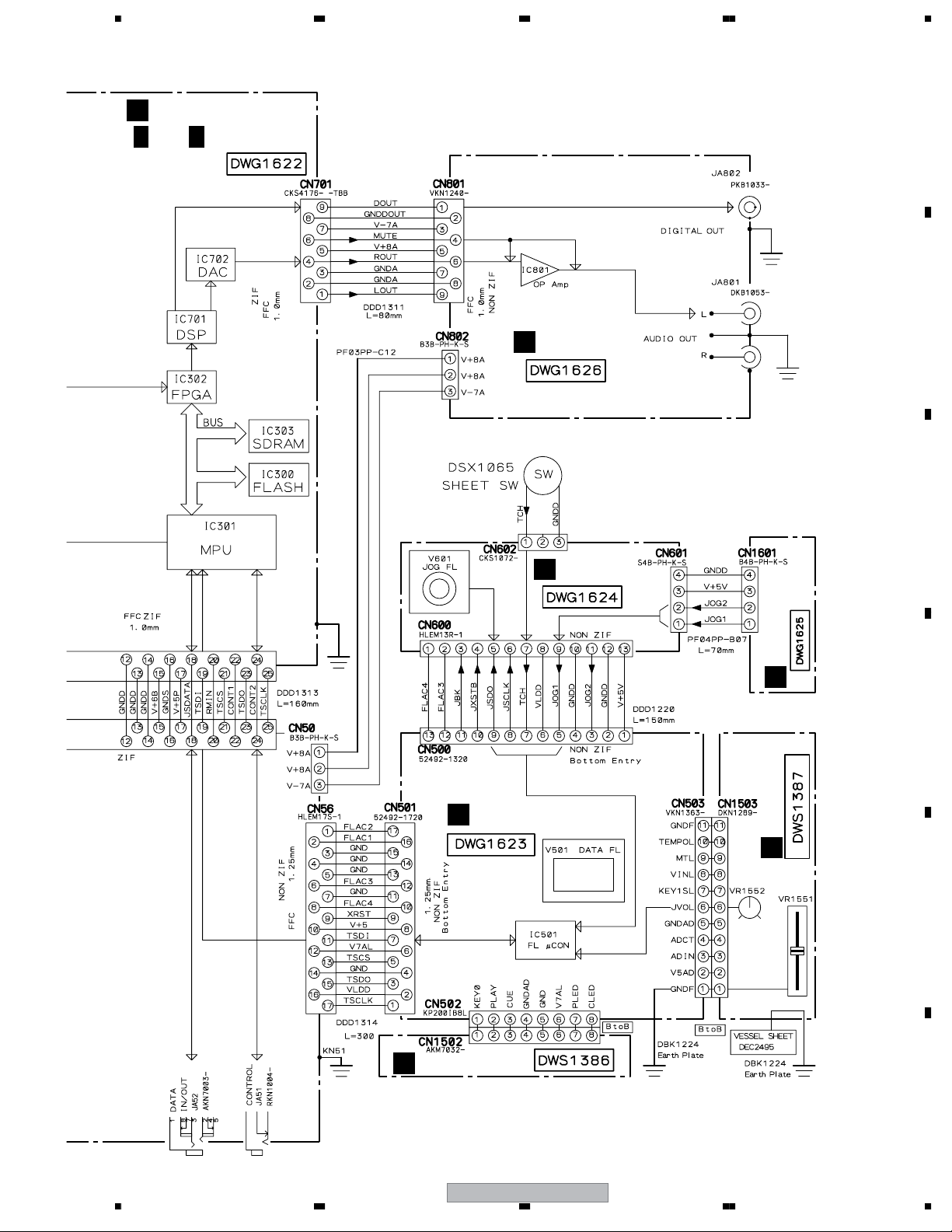
1234
3.6 MAIN ASSY(2/3)
A 2/3
A
Large size
SCH diagram
B
C
MAIN ASSY (DWG1622) (1/2)
1/2
(Data)
2/2
(Data)
(Data)
(Data)
C
CN53
22
1/2
D
(Data)
E
: PANEL DATA (Digital)
(Data)
(Data)
18
(Data)
2/3
A
F
26
1234
71
CDJ-800MK2
5678
A
3/3
A
24
27
26
B
C
19
D
56
CDJ-800MK2
36
E
MODE
MODE
F
27
7
8
A
A 2/3
B
1234
MAIN ASSY (DWG1622) (2/2)
25
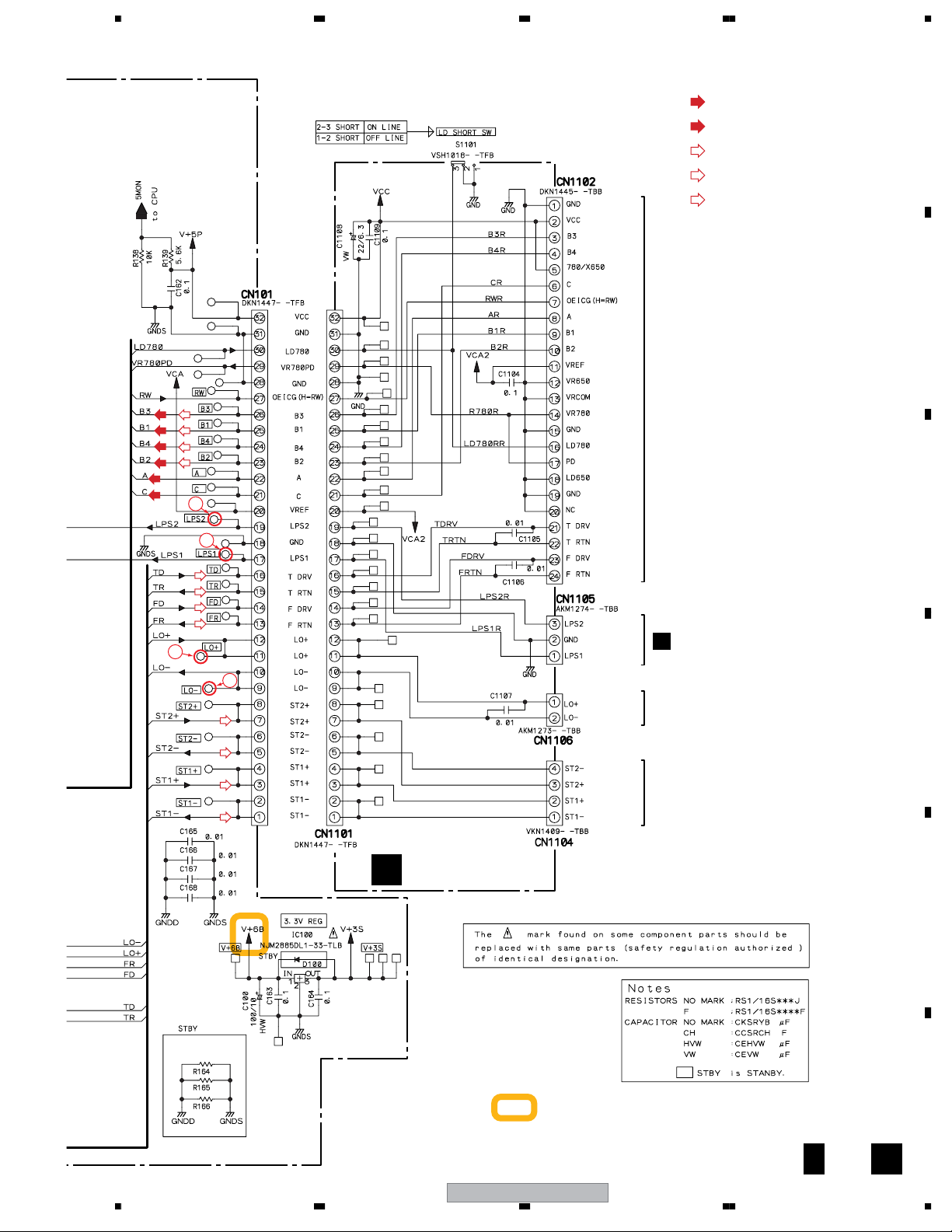
: The Power supply is shown with the marked box.
C
Large size
SCH diagram
30
(Data) (Data)
1/2
D
(Data) (Data)
2/2
E
F
A 2/3
28
to ICE BOARD
2/2
CDJ-800MK2
1234
5678
A
B
23
3/3
A
3/3
A
C
D
E
(Data)
: PANEL DATA (Digital)
CDJ-800MK2
56
F
A 2/3
29
7
8
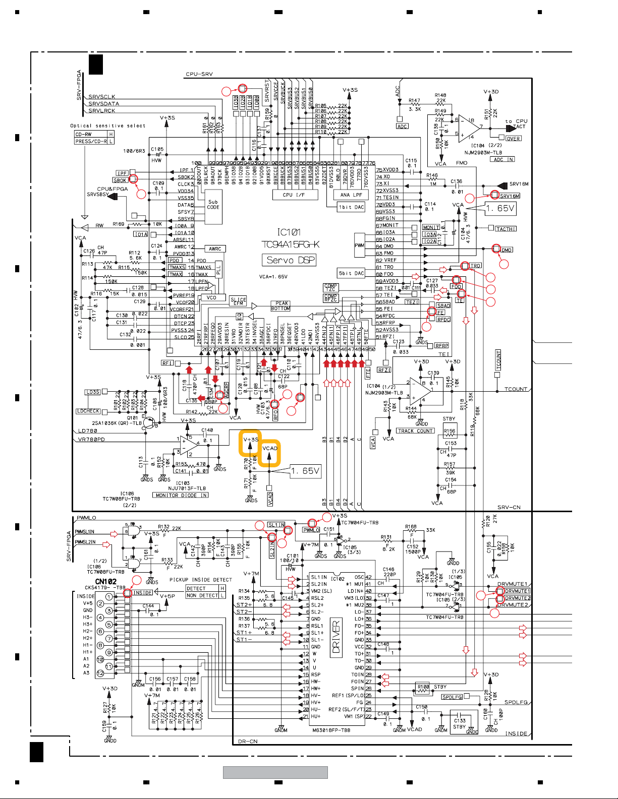
1234
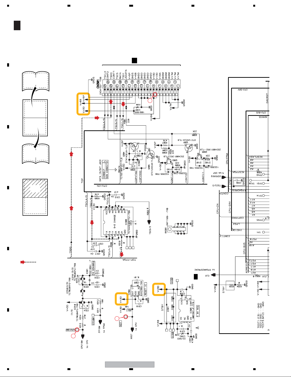
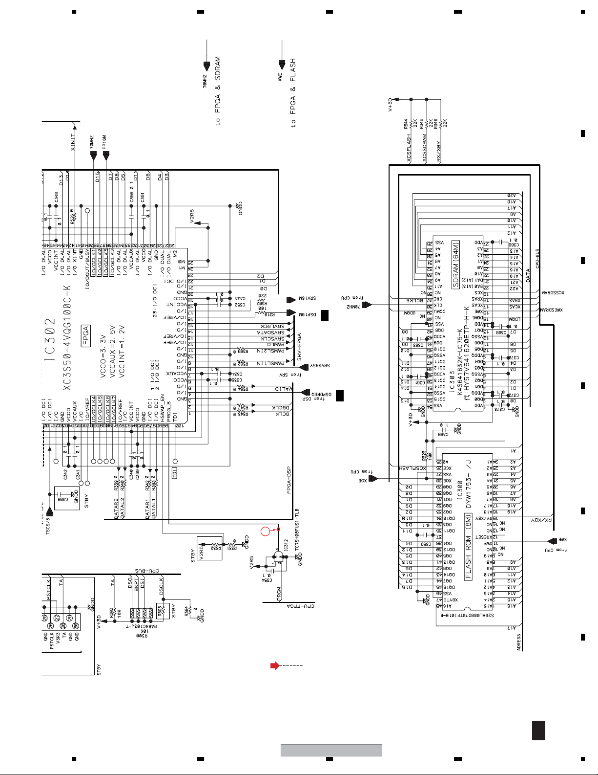
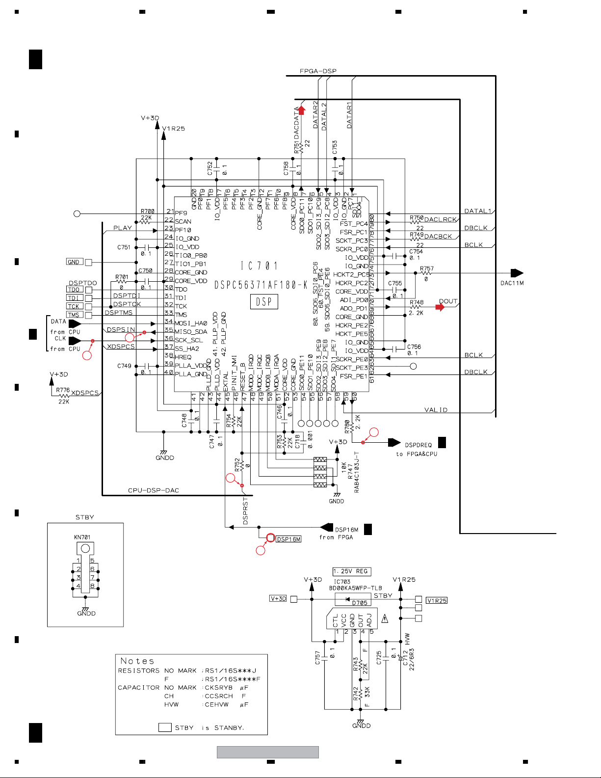
3.7 MAIN ASSY(3/3)
A 3/3
A
B
C
A
2/3
MAIN ASSY (DWG1622)
(Data)
31
32
34
2/3
D
21
2/3
A
29
E
A
F
A 3/3
30
CDJ-800MK2
1234
 Loading...