

Pioneer CDJ-800 Service Manual
PIONEER CORPORATION 4-1, Meguro 1-chome, Meguro-ku, Tokyo 153-8654, Japan
PIONEER ELECTRONICS (USA) INC. P.O. Box 1760, Long Beach, CA 90801-1760, U.S.A.
PIONEER EUROPE NV Haven 1087, Keetberglaan 1, 9120 Melsele, Belgium
PIONEER ELECTRONICS ASIACENTRE PTE. LTD. 253 Alexandra Road, #04-01, Singapore 159936
PIONEER CORPORATION 2002
CDJ-800
COMPACT DISC PLAYER
CDJ-800
THIS MANUAL IS APPLICABLE TO THE FOLLOWING MODEL(S) AND TYPE(S).
Model Type Power Requirement Remarks
CDJ-800 KUCXJ AC120V
CDJ-800 WYXJ AC220-240V
ORDER NO.
RRV2690
For details, refer to "Important symbols for good services" .
T-ZZR OCT. 2002 2002 printed in Japan
1234
-
d
y
u
SAFETY INFORMATION
A
This service manual is intended for qualified service technicians ; it is not meant for the casual do-it
yourselfer. Qualified technicians have the necessary test equipment and tools, and have been traine
to properly and safely repair complex products such as those covered by this manual.
Improperly performed repairs can adversely affect the safety and reliability of the product and ma
void the warranty. If you are not qualified to perform the repair of this product properly and safely, yo
should not risk trying to do so and refer the repair to a qualified service technician.
WARNING
This product contains lead in solder and certain electrical parts contain chemicals which are known to the state of California to cause
cancer, birth defects or other reproductive harm.
B
NOTICE
(FOR CANADIAN MODEL ONLY)
Fuse symbols (fast operating fuse) and/or (slow operating fuse) on PCB indicate that replacement par ts must
be of identical designation.
REMARQUE
(POUR MODÈLE CANADIEN SEULEMENT)
Les symboles de fusible (fusible de type rapide) et/ou (fusible de type lent) sur CCI indiquent que les pièces
de remplacement doivent avoir la même désignation.
C
(FOR USA MODEL ONLY)
Health & Safety Code Section 25249.6 – Proposition 65
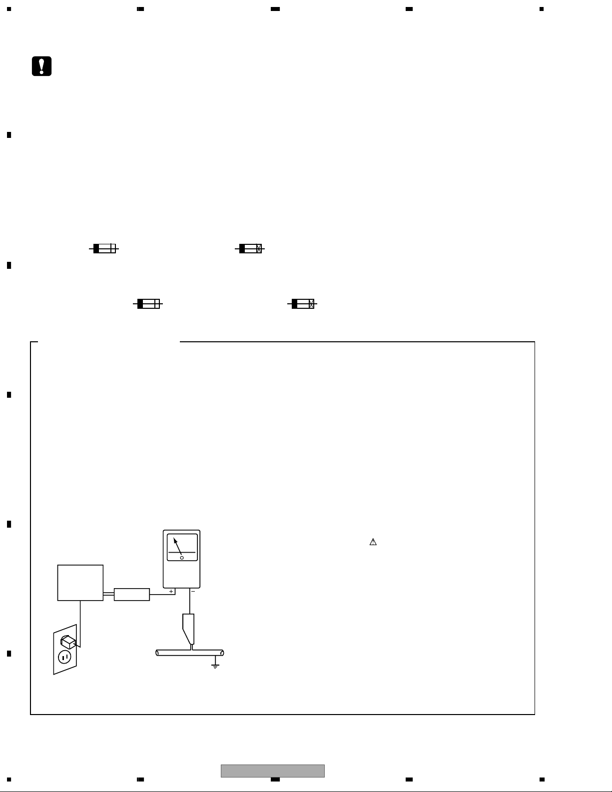
1. SAFETY PRECAUTIONS
The following check should be performed for the
continued protection of the customer and service
technician.
ANY MEASUREMENTS NOT WITHIN THE LIMITS
OUTLINED ABOVE ARE INDICATIVE OF A POTENTIAL
SHOCK HAZARD AND MUST BE CORRECTED BEFORE
RETURNING THE APPLIANCE TO THE CUSTOMER.
LEAKAGE CURRENT CHECK
Measure leakage current to a known earth ground (water
pipe, conduit, etc.) by connecting a leakage current tester
D
E
such as Simpson Model 229-2 or equivalent between the
earth ground and all exposed metal parts of the appliance
(input/output terminals, screwheads, metal overlays, control
shaft, etc.). Plug the AC line cord of the appliance directly
into a 120V AC 60Hz outlet and turn the AC power switch
on. Any current measured must not exceed 0.5mA.
Reading should
not be above
0.5mA
Earth
ground
Device
under
test
Also test with
plug reversed
(Using AC adapter
plug as required)
Test all
exposed metal
surfaces
Leakage
current
tester
2. PRODUCT SAFETY NOTICE
Many electrical and mechanical parts in the appliance
have special safety related characteristics. These are
often not evident from visual inspection nor the protection
afforded by them necessarily can be obtained by using
replacement components rated for voltage, wattage, etc.
Replacement parts which have these special safety
characteristics are identified in this Service Manual.
Electrical components having such features are identified
by marking with a
in this Service Manual.
The use of a substitute replacement component which does
not have the same safety characteristics as the PIONEER
recommended replacement one, shown in the parts list in
this Service Manual, may create shock, fire, or other hazards.
Product Safety is continuously under review and new
instructions are issued from time to time. For the latest
information, always consult the current PIONEER Service
Manual. A subscription to, or additional copies of, PIONEER
Service Manual may be obtained at a nominal charge from
PIONEER.
on the schematics and on the parts list
AC Leakage Test
F
2
1234
CDJ-800
5678
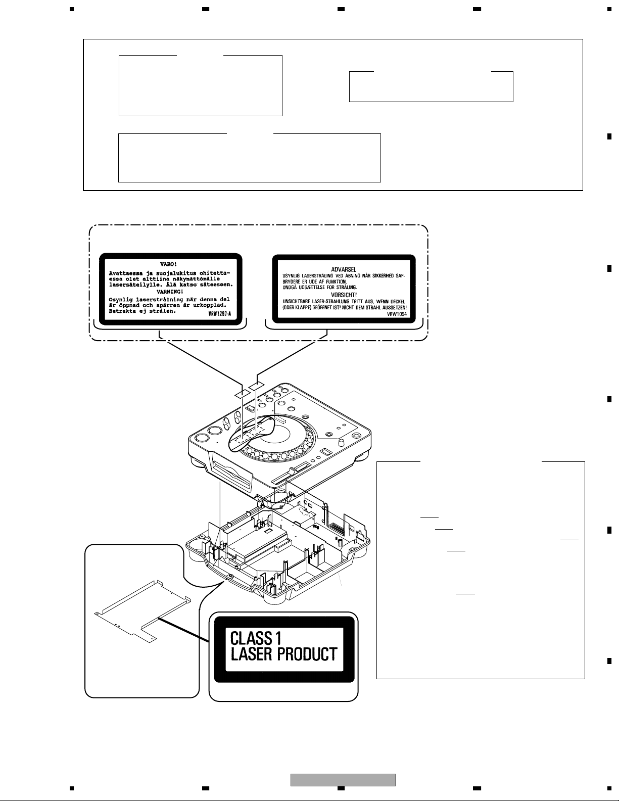
IMPORTANT
THIS PIONEER APPARATUS CONTAINS
LASER OF CLASS 1.
SERVICING OPERATION OF THE APPARATUS
SHOULD BE DONE BY A SPECIALLY
INSTRUCTED PERSON.
LASER DIODE CHARACTERISTICS
MAXIMUM OUTPUT POWER: 5 mW
WAVELENGTH: 780 – 785 nm
WARNING !
The AEL(accessible emission level) of the laser power output is less then CLASS 1
but the laser component is capable of emitting radiation exceeding the limit for
CLASS 1.
A specially instructed person should servicing operation of the apparatus.
Additional Laser Caution
1. Laser Interlock Mechanism
The position of the switch (S1901) for detecting loading
completion is detected by the system microprocessor, and
the design prevents laser diode oscillation when the switch
is not in LPS1 terminal side (when the mechanism is not
clamped and LPS1 signal is high level.) Thus, the interlock
will no longer function if the switch is deliberately set to LPS1
terminal side. ( if LPS1 signal is low level ).
In the test mode
∗ the interlock mechanism will not function.
Laser diode oscillation will continue, if pin 9 of TA2153FN
(IC118)on the MAIN ASSY is connected to GND,
or pin 10 of IC118 (LDON) is connected to low level
(ON), or else the terminals of Q110 are shorted to each
other (fault condition).
2. When the cover is opened, close viewing of the objective
lens with the naked eye will cause exposure to a Class 1
laser beam.
∗ : Refer to page 53.
CDJ-800 WYXJ : Types Only
Printed on the Bottom Plate
Bottom Plate
LABEL CHECK
A
B
C
D
E
F
56
CDJ-800
7
8
3

1234
[ Important symbols for good services ]
In this manual, the symbols shown-below indicate that adjustments, settings or cleaning should be made securely.
A
When you find the procedures bearing any of the symbols, be sure to fulfill them:
1. Product safety
You should conform to the regulations governing the product (safety, radio and noise, and other regulations), and
should keep the safety during servicing by following the safety instructions described in this manual.
2. Adjustments
To keep the original performances of the product, optimum adjustments or specification confirmation is indispensable.
In accordance with the procedures or instructions described in this manual, adjustments should be performed.
3. Cleaning
B
For optical pickups, tape-deck heads, lenses and mirrors used in projection monitors, and other parts requiring cleaning,
proper cleaning should be performed to restore their performances.
4. Shipping mode and shipping screws
To protect the product from damages or failures that may be caused during transit, the shipping mode should be set or
the shipping screws should be installed before shipping out in accordance with this manual, if necessary.
5. Lubricants, glues, and replacement parts
Appropriately applying grease or glue can maintain the product performances. But improper lubrication or applying
glue may lead to failures or troubles in the product. By following the instructions in this manual, be sure to apply the
prescribed grease or glue to proper portions by the appropriate amount.For replacement parts or tools, the prescribed
C
ones should be used.
[ NOTES ON SERVICING ]
7 CLEARNING
D
E
Before shipping out the product, be sure to clean the following positions by using the prescribed cleaning tools:
Position to be cleaned Cleaning tools
Pickup leneses Cleaning liquid : GEM1004
Cleaning paper : GED-008
F
4
1234
CDJ-800

5678
CONTENTS
SAFETY INFORMATION......................................................................................................................................2
1. SPECIFICATIONS.............................................................................................................................................6
2. EXPLODED VIEWS AND PARTS LIST.............................................................................................................8
2.1 PACKING ....................................................................................................................................................8
2.2 EXTERIOR SECTION ..............................................................................................................................10
2.3 CONTROL PANEL SECTION...................................................................................................................12
2.4 SLOT-IN MECHANISM SECTION ............................................................................................................14
3. BLOCK DIAGRAM AND SCHEMATIC DIAGRAM ..........................................................................................16
3.1 BLOCK DIAGRAM....................................................................................................................................16
3.2 OVERALL WIRING DIAGRAM .................................................................................................................18
3.3 MAIN ASSY(1/2).......................................................................................................................................20
3.4 MAIN ASSY(2/2).......................................................................................................................................22
3.5 AC IN, TRNS, SECB and REGB ASSYS..................................................................................................24
3.6 MFLB, SLMB and KSWB ASSYS.............................................................................................................26
3.7 JFLB, SLDB and JOGB ASSYS ...............................................................................................................28
4. PCB CONNECTION DIAGRAM ......................................................................................................................35
4.1 MAIN ASSY ..............................................................................................................................................36
4.2 AC IN and TRNS ASSYS..........................................................................................................................38
4.3 SECB, REGB and SLMB ASSYS.............................................................................................................40
4.4 MFLB and KSWB ASSYS.........................................................................................................................42
4.5 SLDB, JOGB and JFLB ASSYS ...............................................................................................................46
5. PCB PARTS LIST............................................................................................................................................50
6. ADJUSTMENT ................................................................................................................................................54
7. GENERAL INFORMATION .............................................................................................................................55
7.1 DIAGNOSIS..............................................................................................................................................55
7.1.1 SERVICE MODE ...................................................................................................................................55
7.1.2 POWER ON SEQUENCE......................................................................................................................60
7.1.3 DISASSEMBLY......................................................................................................................................62
7.2 PARTS ......................................................................................................................................................65
7.2.1 IC ...........................................................................................................................................................65
7.2.2 DISPLAY................................................................................................................................................75
8. PANEL FACILITIES .........................................................................................................................................76
A
B
C
D
E
F
56
CDJ-800
7
8
5
1234
1. SPECIFICATIONS
A
1. General
System
Power requirements
Power requirements
Power consumption
Power consumption
Operating temperature
Operating humidity
(There should be no condensation of moisture.)
B
Weight
Dimensions
..............................
................................................
.............................................................
....................
12 - 5/8 (W) x 13 -17/32 (D) x 4 - 1/4 (H) in
Compact disc digital audio system
......................... (KUCXJ)AC 120 V, 60 Hz
...............(WYXJ)AC 220 -240V, 50/60 Hz
............................................ (KUCXJ)18 W
..............................................(WYXJ)21 W
......................................
305 (W)x 344.1 (D) x 108.5 (H) mm
+5
°C to +35°C
5% to 85%
3.9 kg (8.6 lb)
2. Audio section
Frequency response
Signal-to-noise ratio
Distortion
..............................................0.006% (JEITA)
.................................4 Hz to 20 kHz
...................115 dB or more (JEITA)
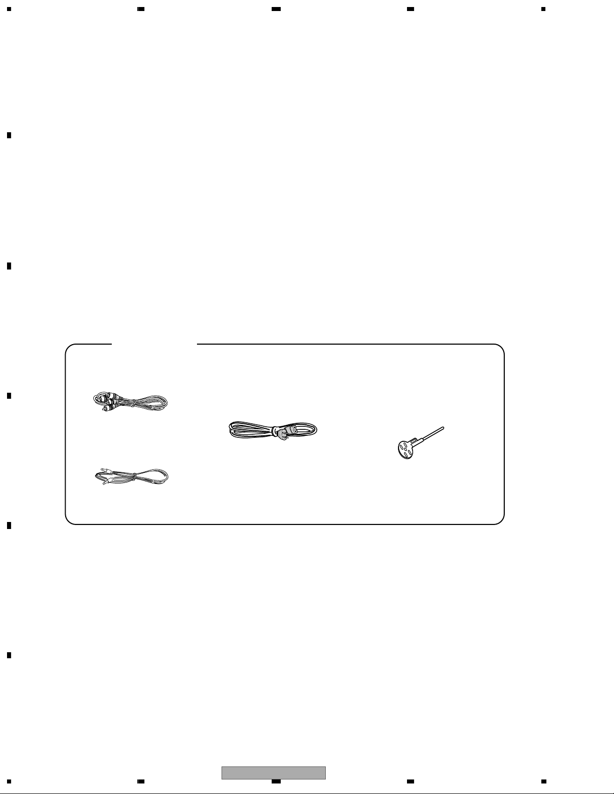
3. Accessories
÷ Operating instructions
÷ Power cord
÷ Audio cable
÷ Control cord.............................................................
÷ Forced eject pin
(housed in a groove in the bottom panel)
÷ Warranty(KUCXJ)
...............................................................
.............................................................
.............................................
.............................................
...................................................
1
1
1
1
1
1
NOTE:
Specifications and design are subject to possible
modification without notice.
C
Accessories
Audio Cable
(VDE1052) L=1.5m
Power Cord
(ADG1154 : WYXJ)
(ADG7021 : KUCXJ)
Forced Fject Pin
(housed in a groove in
the bottom panel)
(DEX1008)
Control Cord
D
E
F
(PDE-319) L=1 m
6
1234
CDJ-800

5678
A
B
C
D
E
56
CDJ-800
F
7
8
7
1234
2. EXPLODED VIEWS AND PARTS LIST
NOTES:
A
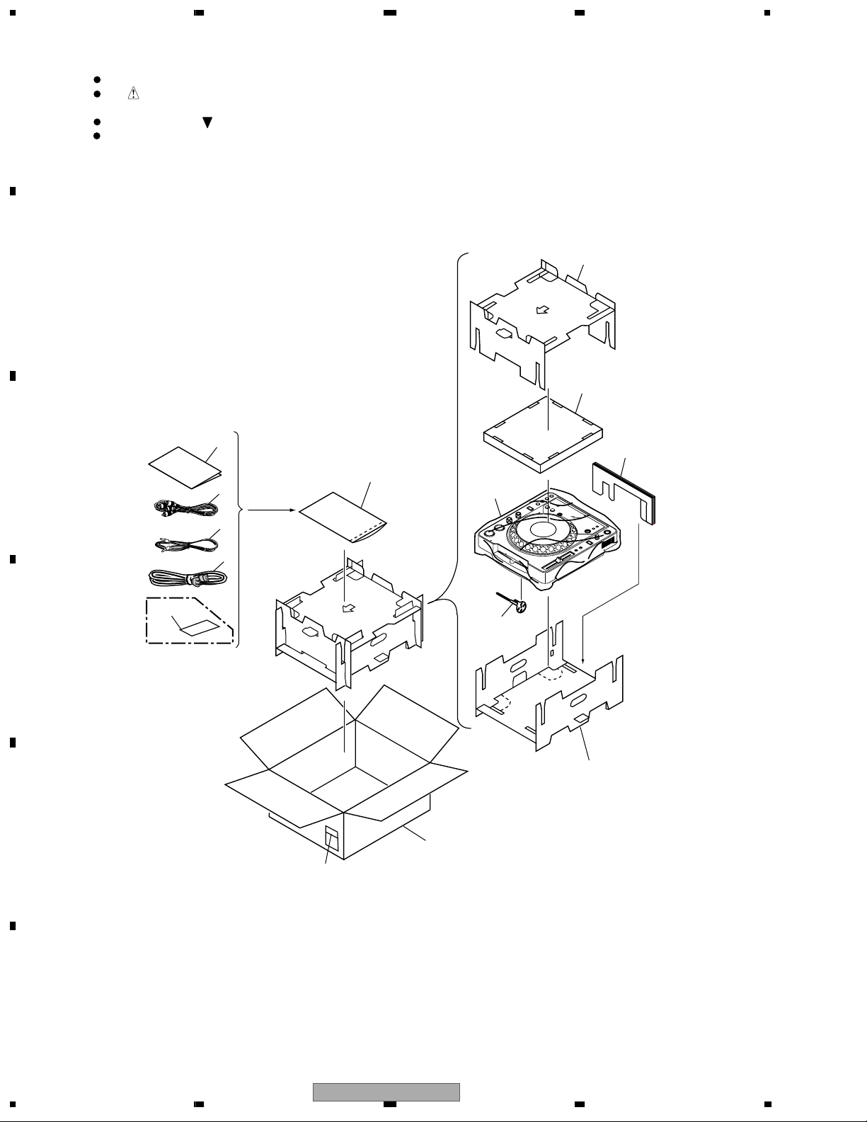
2.1 PACKING
B
C
Parts marked by "NSP" are generally unavailable because they are not in our Master Spare Parts List.
The mark found on some component parts indicates the importance of the safety factor of the part.
Therefore, when replacing, be sure to use parts of identical designation.
Screws adjacent to mark on product are used for disassembly.
For the applying amount of lubricants or glue, follow the instructions in this manual.
(In the case of no amount instructions, apply as you think it appropriate.)
6
7
4
5
3
9
8
2
1
13
10
D
E
KUCXJ type
only
11
12
14
F
8
1234
CDJ-800
>
>
5678
PACKING parts List
Mark
Mark No. Description Part No.
1 AC Power Cord See Contrast table(2)
2 Control Cord PDE-319
3 Audio Cord VDE1052
4 Operating Instructions See Contrast table(2)
5 Polyethylene Bag Z21-038
6 Pad B DHA1556
7 Pad C DHA1557
8 Pad D DHA1558
No. Description Part No.
9 Sheet RHX1006
10 Push Rod DEX1008
11 Pad A DHA1555
12 Packing Case See Contrast table(2)
NSP 13 Warranty Card See Contrast table(2)
NSP 14 Label VRW1629
(2) CONTRAST TABLE
CDJ-800/KUCXJ and WYXJ types are constructed the same except for the following:
Mark No. Symbol and Description
1 AC Power Cord ADG7021 ADG1154
4 Operating Instructions (KUCXJ) DRB1333 Not used
4 Operating Instructions (WYXJ) Not used DRB1332
12 Packing Case DHG2291 DHG2290
NSP 13 Warranty Card ARY7043 Not used
Part No.
KUCXJ WYXJ
A
B
C
D
E
56
CDJ-800
F
7
8
9
1234
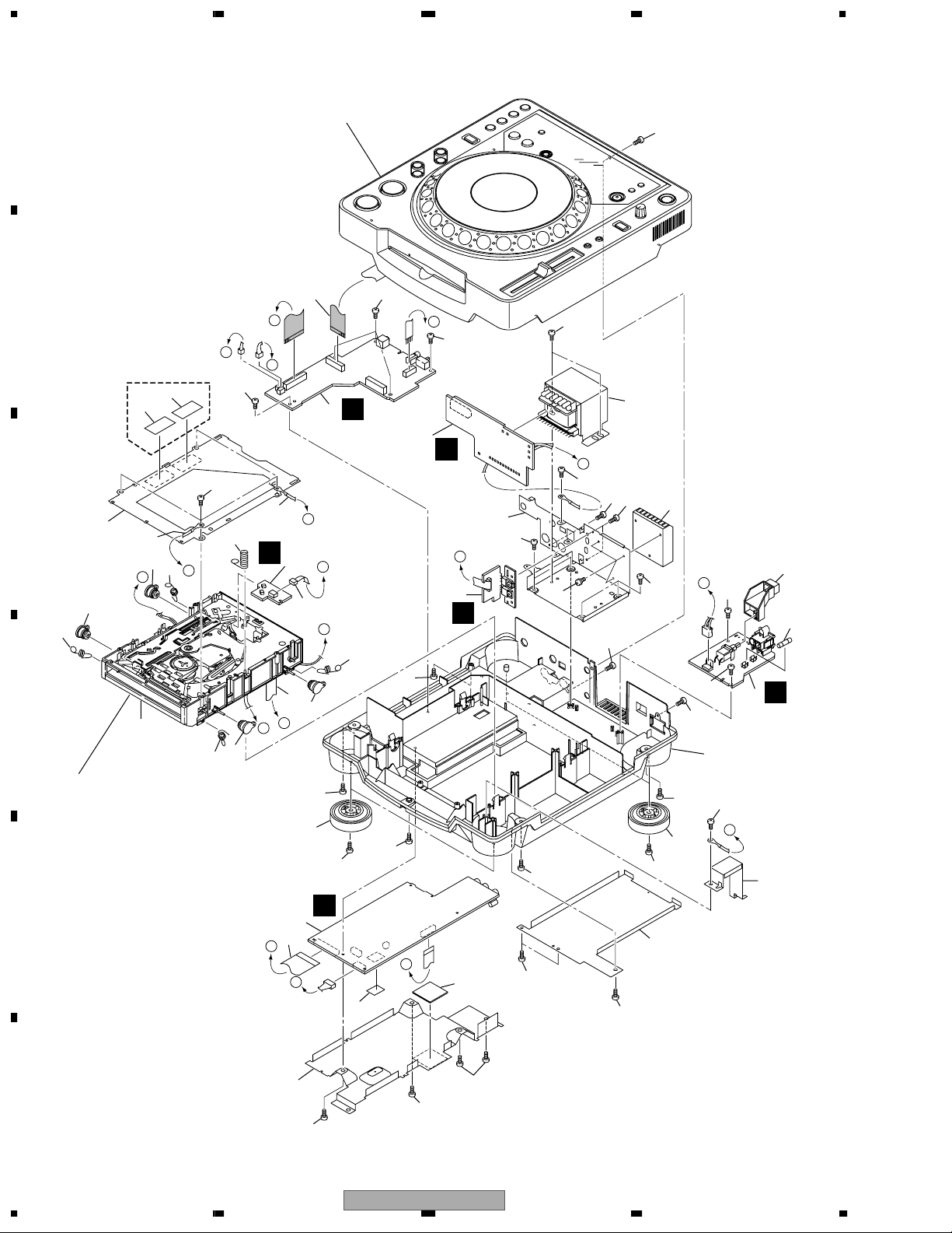
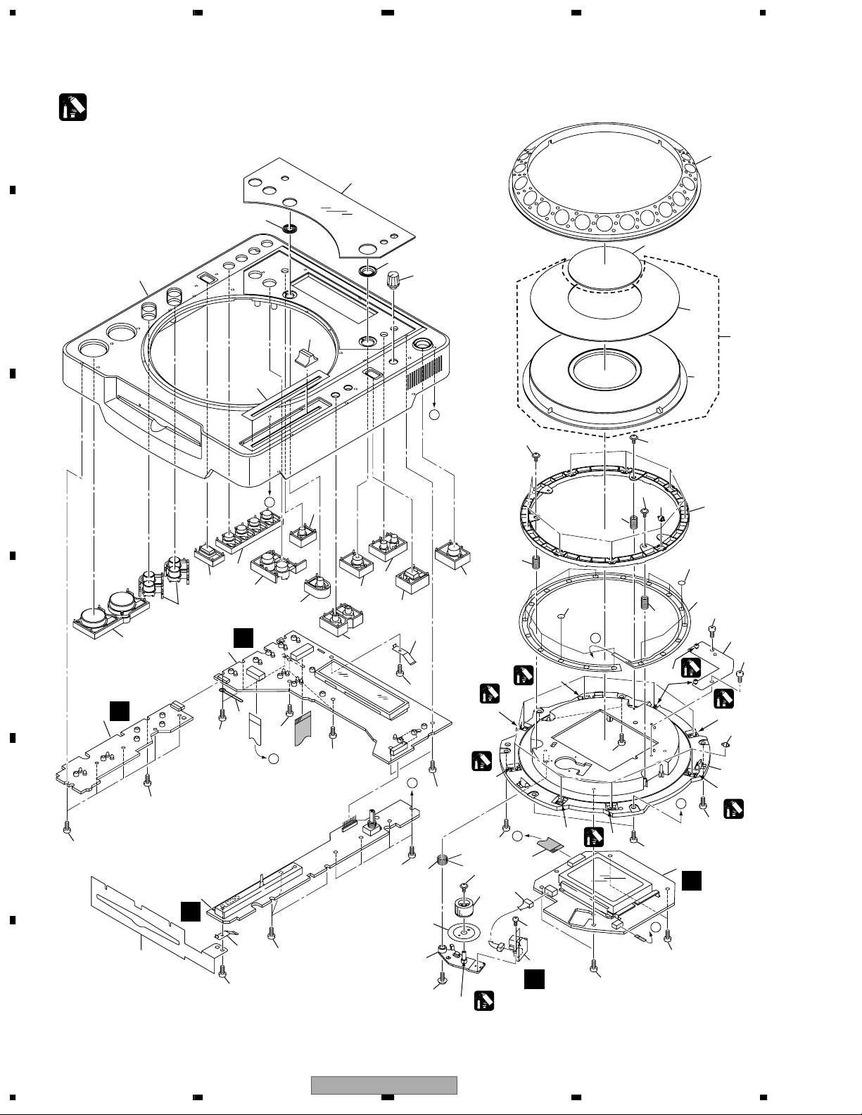
2.2 EXTERIOR SECTION
A
B
WYXJ type only
9
C
D
11
12
15
B
15
16
17
Refer to "2.4 SLOT-IN MECHANISM
SECTION".
16
Refer to "2.3 CONTROL PANEL SECTION".
7
D
B
A
16
33
13
15
33
G
H
10
4
D
E
6
A
14
E
16
18
15
C
33
19
35
8
I
33
33
33
32
F
32
3
C
30
33
F
5
E
33
36
37
G
32
33
33
32
31
33
35
29
19
33
33
33
28
G
33
27
B
2
26
33
I
25
20
23
A
1
24
C
H
21
33
33
22
33
33
32
CDJ-800
E
D
F
10
1234
>
>
>
>
>
5678
EXTERIOR SECTION parts List
Mark
Mark No. Description Part No.
1 MAIN Assy DWG1563
2 AC IN Assy See Contrast table(2)
3 TRNS Assy DWR1364
4 SECB Assy DWR1361
5 REGB Assy DWR1362
6 SLMB Assy DWS1322
7 19P F•F•C/60V DDD1222
8 Caution Label See Contrast table(2)
9 Caution Label HE See Contrast table(2)
10 Earth Lead Unit PDF1104
11 Mecha Plate DNH2339
NSP 12 Cord with Plug DE010VF0
13 Earth Spring DBH1398
14 Connector Assy PG03KK-E22
15 Damper CNV6011
16 Float Spring G5 DBH1494
NSP 17 Slot-in Mecha S4 Assy DXA1946
18 Lead Card 16P DDD1221
19 Insulator Assy DXA1945
No. Description Part No.
20 25P F•F•C/60V DDD1223
NSP 21 Silicon Rubber D5 L DEB1456
22 Bottom Cushion S4 DEC2506
23 Bottom Plate P DNH2531
24 Bottom Plate M DNH2546
25 Earth Plate DNH2532
NSP 26 Chassis See Contrast table(2)
27 FU11 Fuse See Contrast table(2)
28 Power Knob DAC2073
29 Heat Sink DNG1086
30 Trans Plate DNH2529
31 T21 Power Transformer See Contrast table(2)
32 Screw BBZ30P080FMC
33 Screw BPZ30P080FZK
34 . . . . . .
35 Screw IPZ30P100FMC
36 Screw PMA30P060FMC
37 Screw BBZ40P060FMC
(2) CONTRAST TABLE
CDJ-800/KUCXJ and WYXJ types are constructed the same except for the following:
Mark No. Symbol and Description
2 AC IN Assy DWR1366 DWR1363
8 Caution Label Not used VRW1094
9 Caution Label HE Not used PRW1233
NSP 26 Chassis DNK4060 DNK4059
27 FU11 Fuse (1.6A/125V) REK1077 Not used
27 FU11 Fuse (T800mA/L250V) Not used REK1021
31 T21 Power Transformer DTT1169 DTT1168
KUCXJ
Part No.
WYXJ
A
B
C
D
56
CDJ-800
E
F
7
8
11
1234
2.3 CONTROL PANEL SECTION
A
Lubricaing oil : ZLB-PN397B
1
*
7
B
8
11
26
6
27
9
10
29
28
24
B
49
C
A
17
49
35
34
1
*
1
*
1
*
41
46
C
39
44
*
47
5
K
15
14
13-1/2
D
E
46
12
2
H
46
4
46
16
18
F
1
45
46
C
46
J
23
25
46
F
46
19
20
21
46
22
13-2/2
23
46
B
46
40
42
43
48
1
*
35
D
46
1
*
46
49
49
1
46
30
31
35
*
32
34
36
46
37
46
1
1
*
31
38
1
*
A
46
3
I
D
46
12
1234
CDJ-800

5678
CONTROL PANEL SECTION parts List
Mark No. Description Part No.
1 MFLB Assy DWG1564
2 KSWB Assy DWS1321
3 JFLB Assy DWG1565
4 SLDB Assy DWS1323
5 JOGB Assy DWG1566
6 Display Panel DAH2139
7 RELOOP Guard DNK4057
8 Control Panel DNK4054
9 QR Guard DNK4058
10 Rotary Knob C DAA1143
A
11 Slide Knob DAC2067
12 PLAY Knob DAC2059
13 SET Knob (EJECT) DAC2060
14 REVERSE Knob DAC2068
15 AUTO BEAT LOOP Knob DAC2069
16 LOOP Knob DAC2066
17 TIME MODE Knob DAC2065
18 RELOOP Knob DAC2064
19 TEMPO Knob DAC2061
20 QUICK RETURN Knob DAC2070
21 CALL Knob DAC2062
22 VINYL Knob DAC2063
23 Earth Plate (CU) DBK1224
24 Slide Sheet 1C DAH1988
25 Vessel Sheet DEC2495
26 JOG B DNK4068
27 JOG Panel DAH2182
28 JOG Assy-S DXX2521
29 JOG Plate DAH2052
30 JOG A DNK4067
B
C
D
31 Roller A Assy DXB1773
32 SW Ring DNK4070
33 . . . . . .
34 SW Cushion HH48 DEC2523
35 SW Spring DBH1514
36 Sheet SW DSX1060
37 JOG Stay Assy DXB1774
38 JOG Holder DNK4069
39 13P F•F•C/60V DDD1220
40 Arm Spring DBH1503
41 D Gear DNK4066
42 ENC Plate DEC2498
43 Gear Arm DNK4065
44 Connector Assy PF04PP-B07
45 Cord Clamper RNH-184
46 Screw BPZ30P080FZK
47 Screw BPZ20P060FMC
48 Screw IPZ30P100FMC
49 Screw PBA1062
56
CDJ-800
E
F
7
8
13
1234
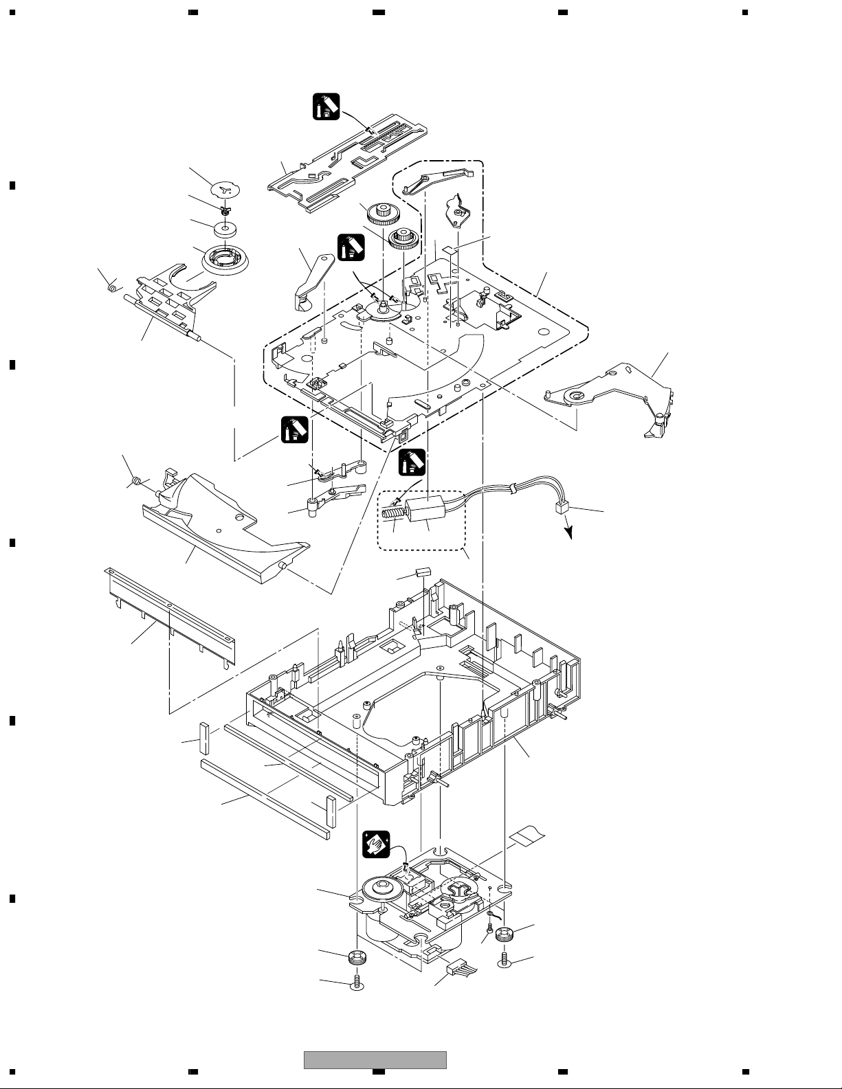
2.4 SLOT-IN MECHANISM SECTION
A
7
B
15
C
8
Paint grease the inner
surface of the wall.
11
13
32
10
Paint on side of axle.
23
Paint grease the inner
Paint grease the inner
surface of the wall.
surface of the wall.
Dyefree
Dyefree
(ZLX-ME413A)
(ZLX-ME413A)
18
Grease
(ZLB-PN397B)
12
(ZLB-PN397B)
22
21
Grease
Grease
(ZLB-PN397B)
33
Grease
(ZLB-PN397B)
9
16
17
1
14
19
20
24
To MAIN Assy
28
2
D
4
25
5
3
25
E
6
27
26
26
F
14
1234
30
29
CDJ-800
31
30

5678
SLOT-IN MECHANISM SECTION parts List
Mark No. Description Part No.
1 Connector Assy DKP3522
2 Spacer Por (T3) DEB1566
3 Float Base S4 Assy DXB1772
4 Front Sheet DED1132
5 Vessel Cushion A DEC2455
6 Vessel Cushion B DEC2456
7 Clamp Spring DBH1374
8 Guide Spring DBH1375
9 SW. Lever Spacer (Pet) DEC2420
10 Clamp Magnet DMG1009
A
11 Yoke S4 DNH2528
12 Loading Lever DNK3406
13 Main Cam DNK3407
14 Disc Guide DNK3478
15 Clamp Arm DNK3576
16 Loading Base Assy-S DEA1022
17 Eject Lever DNK3684
18 Lever AP DNK3835
19 Lever BP DNK3836
NSP 20 Worm Gear DNK3410
21 Loading Gear DNK3409
22 Drive Gear DNK3565
23 Clamper S4 DNK4072
NSP 24 DC Motor DXM1173
25 Vessel Cushion C DEC2457
26 Float Rubber S4 DEB1568
27 CD Mechanism DXA-DA114
28 DC Motor Assy-S DXX2510
29 Connector Assy (6P) PF06PP-B25
30 Screw DM DBA1104
B
C
D
31 Screw BBZ20P040FMC
32 Centering Guide DNK4073
NSP 33 Loading Base DNK3637
56
CDJ-800
E
F
7
8
15
1234
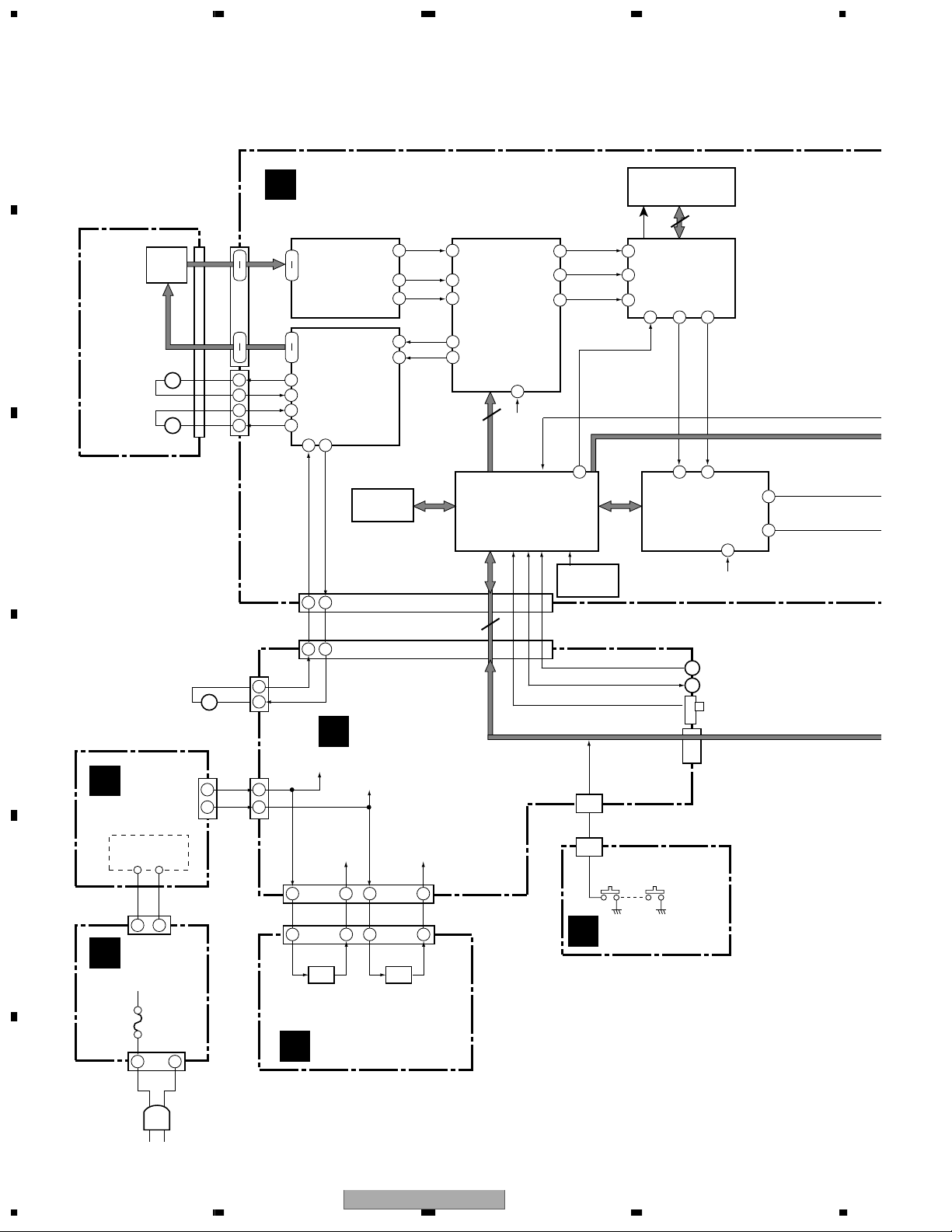
3. BLOCK DIAGRAM AND SCHEMATIC DIAGRAM
3.1 BLOCK DIAGRAM
A
MAIN ASSY
A
CD MECHANISM
PICKUP
ASSY
B
SLED
MOTOR
SPINDLE
MOTOR
+–
M
+–
M
C
LOADING
D
MOTOR
CN22
(11P)
C
TRNS ASSY
11
M
9
A-F
T+,TF+,F-
SL+
SL-
SP-
SP+
CN113
9
14
1
4
3
4
2 8
1 9
CN111
LO-
LO+
+–
V+7B
V+11B
(16P)
A-F
T+,TF+,F-
(6P)
2
1
11
9
CN122
(25P)
CN53
(25P)
CN54
CN51
(11P)
4
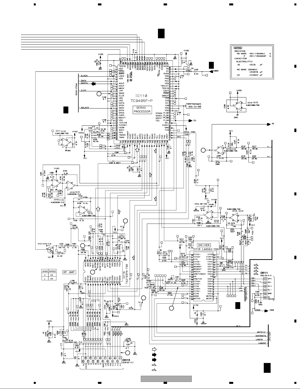
TA2153FN
7
RF AMP
11
14
6
BTL DRIVER
7
4
5
2 1
LO- LO+
24
25
D
V+7B
RFO
TEO
FEO
IC113
BR24C64F
EEPROM
25
14
17
18
19
IC118
IC119
LA6562
SECB ASSY
V+11B
Clock
Enable
RFI
38
TEI
46
FEI
43
FOO
48
TRO
49
Parallel data
BUS0
BUS1
BUS2
BUS3
Serial data in
data out
IC110
TC9495F
SERVO
PROCESSOR
78
16MHz
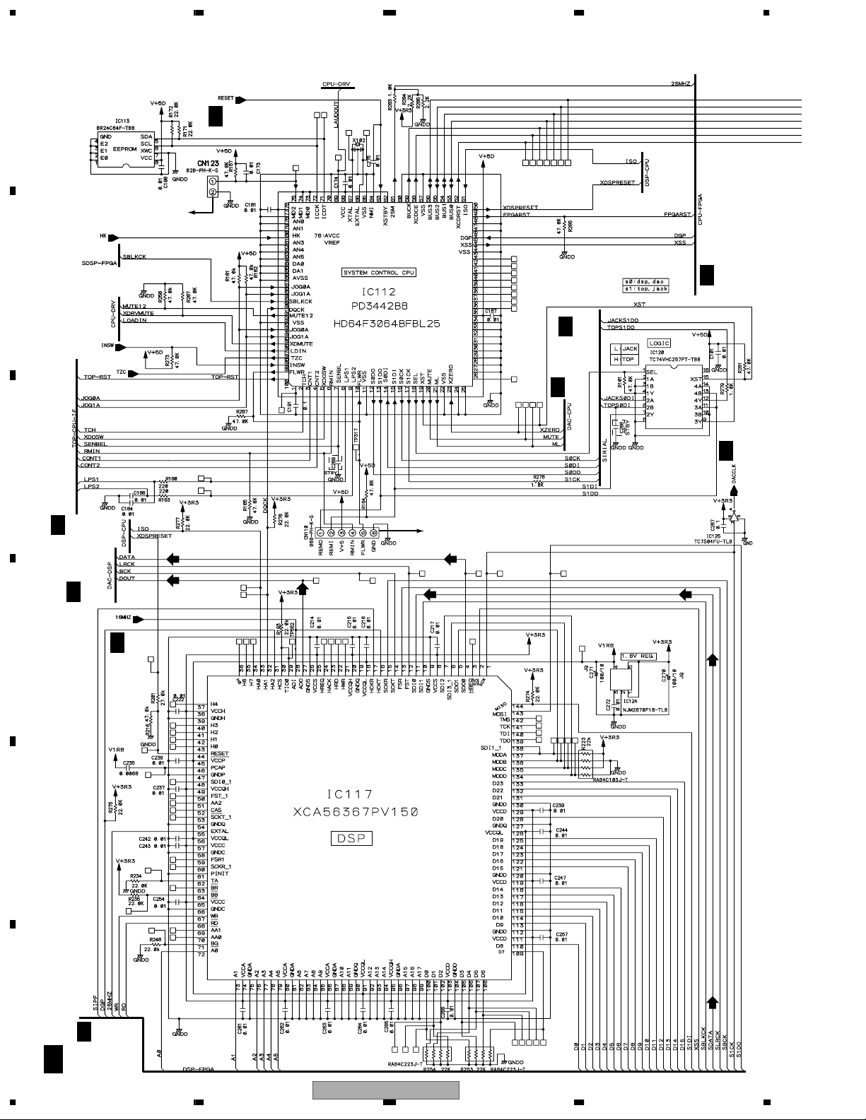
IC112
PD3442B8
SYSTEM CONTROL
MICROCOMPUTER
AOUT
8 83
LRCK
5 85
BCK
7 84
25MHz
61
IC122
M51957BFP
RESET IC
CN55
(3P)
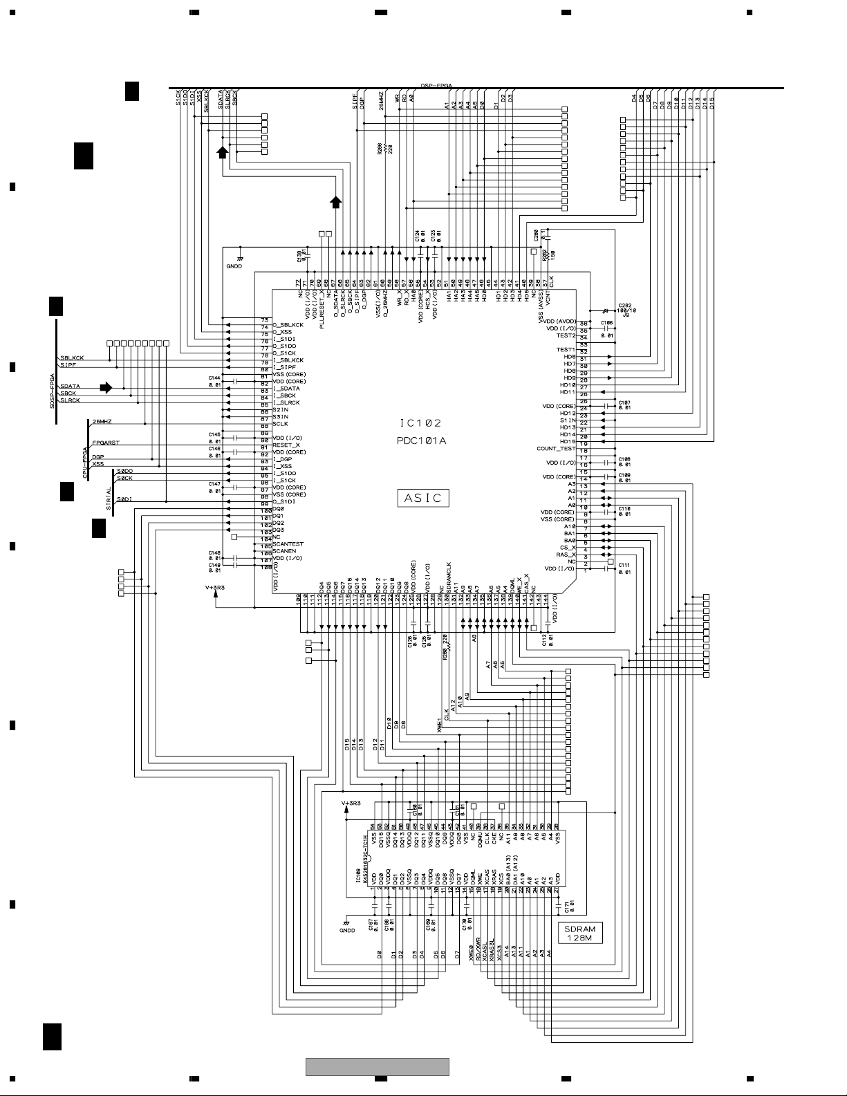
IC109
K4S281632C-TC1H
SDRAM
LR Clock Audio
50MHz
88 67 60
25MHz 25MHz
BCK
Data
IC102
PDC101A
ASIC
O_SDATA
25MHz
11 55
IC117
XCA56367PV150
DSP
CONTROL
DATA IN/OUT
DIGITAL OUT MODE SW
NORMAL— DJ
CN56
(19P)
28
16MHz
SDOO
ADO
4
27
T21 PT
E
1 2
CN11
B
AC IN ASSY
AN11
LIVE
1 2
NEUTRAL
E
V+5D V+7A
1
1 3
IC91
BA05T
REG.
3
REGB ASSY
4 5
4 5
IC92
PQ15RW11
REG.
CN52
(6P)
J91
(6P)
CN1901
(3P)
LOADING PHASE SW
SLMB ASSY
G
F
AC IN
16
CDJ-800
1234

5678
A
B
CN110
ONLY DESIGNER USER
IC104
PE8001A
2 16
DAC
16MHz
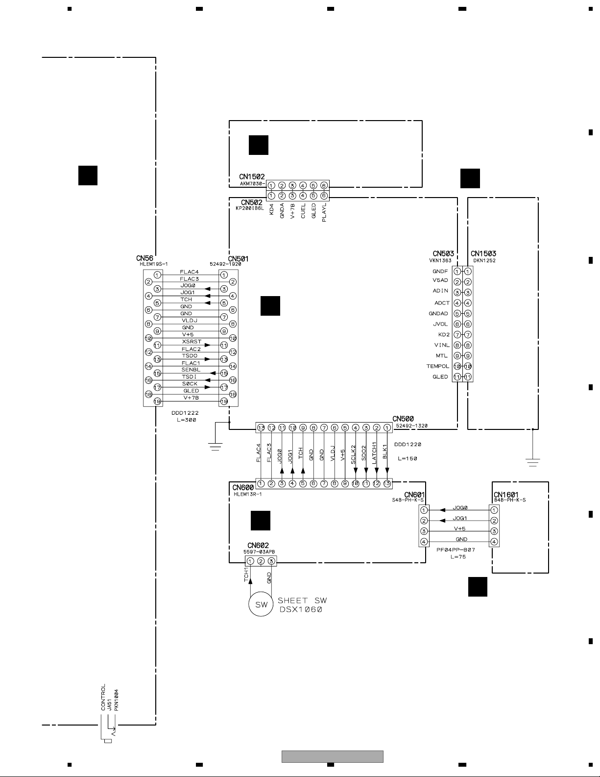
MFLB ASSY
F
CN501
(19P)
PANEL KEY
PANEL KEY
KSWB ASSY
H
IC103 (1/2)
NJM4558MD
IC501
PD5848A
DISPLAY
MICROCOMPUTER
CN502
CN1502
(6P)
2
1
3
4MHz
Serial data
Latch clock
(6P)
CN500
(13P)
Serial data
CN600
(13P)
CN601
(4P)
AUDIO
L
OUT
DIGITAL
OUT
IC502
UPD16306B
FL DRIVER
IC601
UPD16306B
FL DRIVER
JFLB ASSY
I
V501
MAIN FL
V601
JOG FL
CN503
(11P)
CN1503
SHEET SW
CN602
(3P)
SLDB ASSY
J
(11P)
PANEL KEY
Slider
VR
C
D
E
CN1601
(4P)
JOGB ASSY
K
JOG ENCODER
CDJ-800
56
F
7
8
17
1234
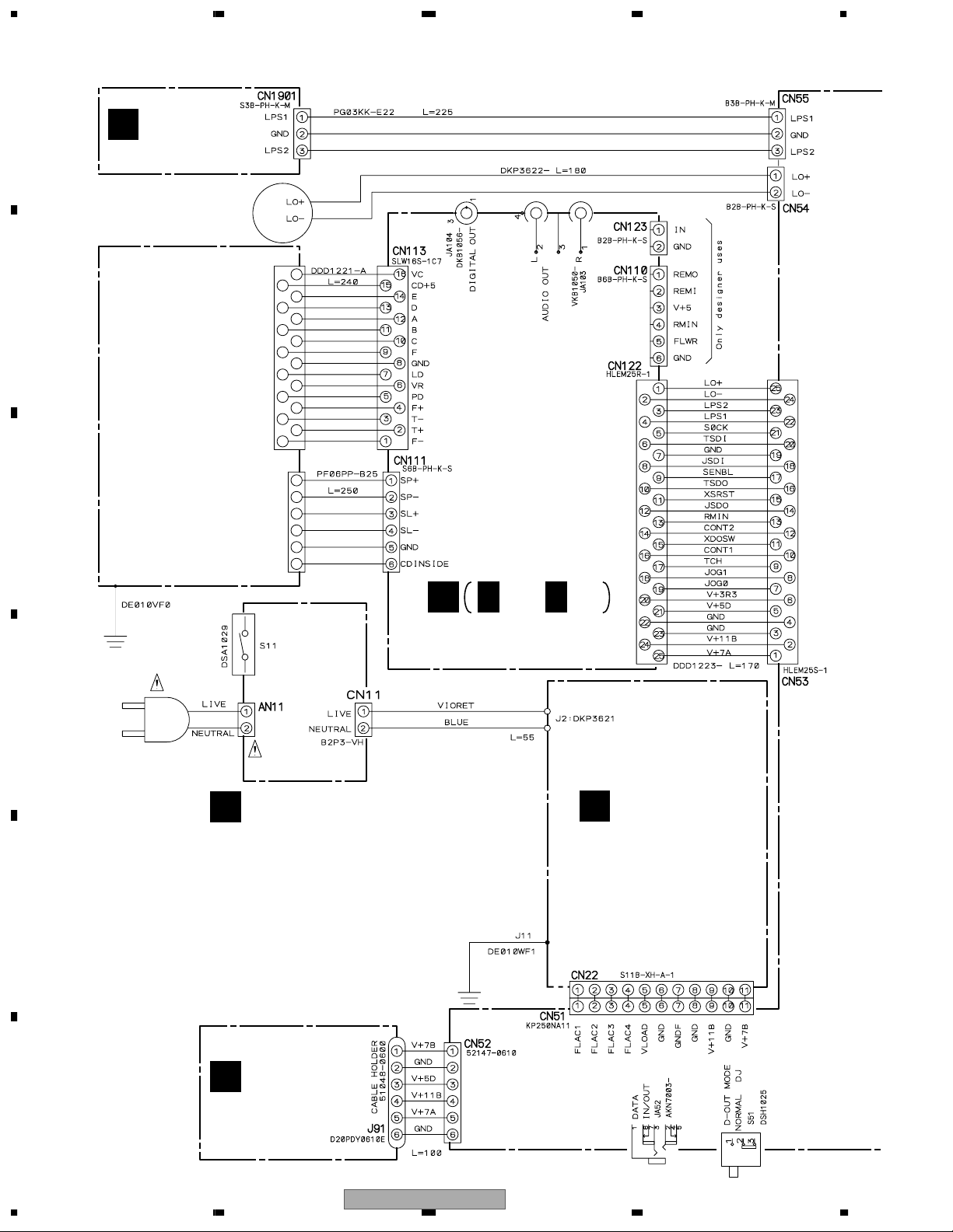
3.2 OVERALL WIRING DIAGRAM
A
SLMB ASSY
G
(DWS1322)
LOADING MOTOR
ASSY-S
DXX2510
B
CD MECHANISM
(DXA-DA114)
C
A
A 1/2- A 2/2
MAIN ASSY
(DWG1563)
AKP7032 (KUCXJ)
BKP1046 (WYXJ)
D
AC POWER CORD
(KUCXJ : ADG7021)
(WYXJ : ADG1154)
AC IN ASSY
B
(KUCXJ : DWR1366)
TRNS ASSY
C
(DWR1364)
(WYXJ : DWR1363)
E
REGB ASSY
E
(DWR1362)
F
18
1234
CDJ-800
5678
D
SECB ASSY
(DWR1361)
Note : When ordering service parts, be sure to refer to
"EXPLODED VIEWS and PARTS LIST" or "PCB PARTS LIST".
KSWB ASSY (DWS1321)
H
MFLB ASSY (DWG1564)
F
SLDB ASSY
J
(DWS1323)
A
B
C
JFLB ASSY (DWG1565)
I
JOGB ASSY
K
(DWG1566)
D
E
F
56
CDJ-800
7
8
19
1234
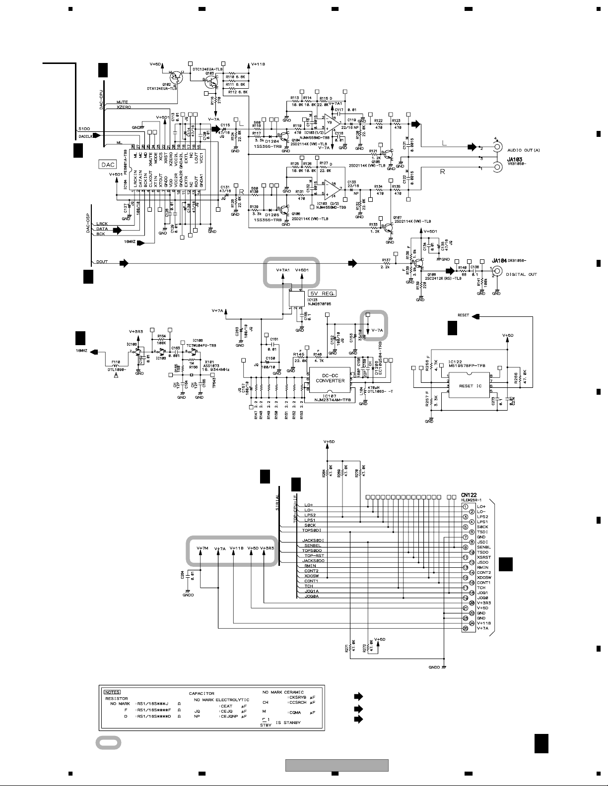
3.3 MAIN ASSY(1/2)
A
ONLY
DESIGNER
USER
A 2/2
DSS1139
B
A 2/2
A 2/2
A 2/2
A 2/2
C
A 2/2
(AD)
A 2/2
D
A 2/2
(D)
(D)
ONLY
DESIGNER
USER
(AD)
(AD)
(AD)
(AD)(AD)
E
F
A 1/2
20
A 2/2
CDJ-800
1234
5678
A 2/2
(AD)
A 1/2
MAIN ASSY
A
(DWG1563)
A 2/2
6
8
(RF)
B
C
(F)
(T) (T)
(RF)
1
2
(F)
3
D
(T)
(T)
4
(T)
7
A 2/2
(F)
(F)
(T)
(T)
E
TO CD MECHANISM
(F)
(T)
(T)
(F)
(RF)
: RF SIGNAL ROUTE
5
TO CD MECHANISM
(AD)
: AUDIO DATA SIGNAL ROUTE
(D)
: DIGITAL OUT SIGNAL ROUTE
(F)
: FOCUS SERVO SIGNAL ROUTE
(T)
: TRACKING SERVO SIGNAL ROUTE
CDJ-800
56
F
A 1/2
7
8
21
1234
3.4 MAIN ASSY(2/2)
A
A 2/2
A 1/2
(AD)
MAIN ASSY
(DWG1563)
(AD)
B
GND
A 1/2
(AD)
C
GND
GND
GND
GND
GND
GND
GND
GND
GND
A 1/2
A 1/2
GND
GND
GND
D
E
GND
GND
GND
GND
GND
F
A 2/2
22
1234
CDJ-800
5678
A 1/2
A 1/2
A 1/2
A 1/2
(AD)
(D) (D)
(D)
A 1/2
A
B
C
A 1/2
A 1/2
: AUDIO SIGNAL ROUTE
(AD)
: AUDIO DATA SIGNAL ROUTE
(D)
: DIGITAL OUT SIGNAL ROUTE
: The power supply is shown with the marked box.
56
CDJ-800
D
CN53
D
E
F
A 2/2
7
8
23
1234
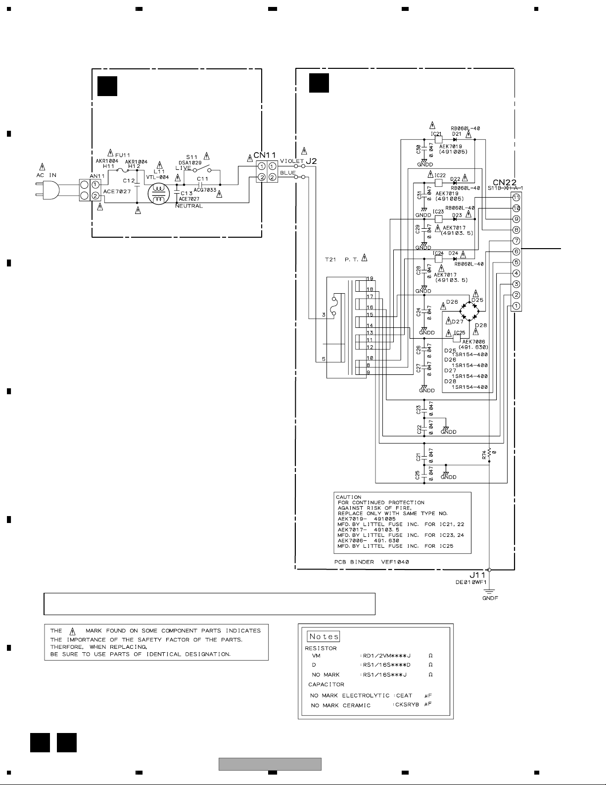
3.5 AC IN, TRNS, SECB and REGB ASSYS
A
AC IN ASSY
B
(KUCXJ : DWR1366)
(WYXJ : DWR1363)
FU11
KUCXJ: 1.6A/125V (REK1077)
WYXJ: T800mA/L250V (REK1021)
LIVE
TRNS ASSY (DWR1364)
C
B
C
D
NEUTRAL
AC POWER CORD
KUCXJ: ADG7021
WYXJ: ADG1154
KUCXJ: DTT1169
WYXJ: DTT1168
E
F
• NOTE FOR FUSE REPLACEMENT
CAUTION -
FOR CONTINUED PROTECTION AGAINST RISK OF FIRE.
REPLACE WITH SAME TYPE AND RATINGS ONLY.
B C
24
1234
CDJ-800
 Loading...