

Page 1

Avid® Symphony™ and
Composer Products
Setup Guide
for the Mac OS® X Operating System
make manage move | media
™
Avid
®
Page 2

Copyright and Disclaimer
Product specifications are subject to change without notice and do not represent a commitment on the part
of Avid Technology, Inc. The software described in this document is furnished under a license agreement.
You can obtain a copy of that license by visiting Avid's Web site at www.avid.com. The terms of that license
are also available in the product in the same directory as the software. The software may not be reverse
assembled and may be used or copied only in accordance with the terms of the license agreement. It is
against the law to copy the software on any medium except as specifically allowed in the license
agreement. Avid products or portions thereof are protected by one or more of the following United States
patents: 4,746,994; 4,970,663; 5,045,940; 5,267,351; 5,309,528; 5,355,450; 5,396,594; 5,440,348;
5,452,378; 5,467,288; 5,513,375; 5,528,310; 5,557,423; 5,568,275; 5,577,190; 5,584,006; 5,640,601;
5,644,364; 5,654,737; 5,715,018; 5,724,605; 5,726,717; 5,729,673; 5,745,637; 5,752,029; 5,754,851;
5,799,150; 5,812,216; 5,852,435; 5,883,670; 5,905,841; 5,929,836; 5,929,942; 5,930,445; 5,946,445;
5,987,501; 5,995,115; 6,016,152; 6,018,337; 6,023,531; 6,035,367; 6,038,573; 6,058,236; 6,061,758;
6,091,778; 6,105,083; 6,118,444; 6,128,001; 6,130,676; 6,134,607; 6,137,919; 6,141,007; 6,141,691;
6,157,929; 6,198,477; 6,201,531; 6,211,869; 6,223,211; 6,239,815; 6,249,280; 6,269,195; 6,301,105;
6,317,158; 6,317,515; 6,327,253; 6,330,369; 6,351,557; 6,353,862; 6,357,047; 6,392,710; 6,404,435;
6,407,775; 6,417,891; 6,426,778; D396,853; D398,912. Additional U.S. and foreign patents pending. No
part of this document may be reproduced or transmitted in any form or by any means, electronic or
mechanical, including photocopying and recording, for any purpose without the express written permission
of Avid Technology, Inc.
Copyright © 2003 Avid Technology, Inc. and its licensors. All rights reserved. Printed in USA.
The following disclaimer is required by Apple Computer, Inc.
APPLE COMPUTER, INC. MAKES NO WARRANTIES WHATSOEVER, EITHER EXPRESS OR IMPLIED,
REGARDING THIS PRODUCT, INCLUDING WARRANTIES WITH RESPECT TO ITS
MERCHANTABILITY OR ITS FITNESS FOR ANY PARTICULAR PURPOSE. THE EXCLUSION OF
IMPLIED WARRANTIES IS NOT PERMITTED BY SOME STATES. THE ABOVE EXCLUSION MAY NOT
APPLY TO YOU. THIS WARRANTY PROVIDES YOU WITH SPECIFIC LEGAL RIGHTS. THERE MAY BE
OTHER RIGHTS THAT YOU MAY HAVE WHICH VARY FROM STATE TO STATE.
The following disclaimer is required by Sam Leffler and Silicon Graphics, Inc. for the use of
their TIFF library:
Copyright © 1988–1997 Sam Leffler
Copyright © 1991–1997 Silicon Graphics, Inc.
Permission to use, copy, modify, distribute, and sell this software [i.e., the TIFF library] and its
documentation for any purpose is hereby granted without fee, provided that (i) the above copyright notices
and this permission notice appear in all copies of the software and related documentation, and (ii) the
names of Sam Leffler and Silicon Graphics may not be used in any advertising or publicity relating to the
software without the specific, prior written permission of Sam Leffler and Silicon Graphics.
THE SOFTWARE IS PROVIDED “AS-IS” AND WITHOUT WARRANTY OF ANY KIND, EXPRESS,
IMPLIED OR OTHERWISE, INCLUDING WITHOUT LIMITATION, ANY WARRANTY OF
MERCHANTABILITY OR FITNESS FOR A PARTICULAR PURPOSE.
IN NO EVENT SHALL SAM LEFFLER OR SILICON GRAPHICS BE LIABLE FOR ANY SPECIAL,
INCIDENTAL, INDIRECT OR CONSEQUENTIAL DAMAGES OF ANY KIND, OR ANY DAMAGES
WHATSOEVER RESULTING FROM LOSS OF USE, DATA OR PROFITS, WHETHER OR NOT ADVISED
OF THE POSSIBILITY OF DAMAGE, AND ON ANY THEORY OF LIABILITY, ARISING OUT OF OR IN
CONNECTION WITH THE USE OR PERFORMANCE OF THIS SOFTWARE.
The following disclaimer is required by the Independent JPEG Group:
Portions of this software are based on work of the Independent JPEG Group.
Page 3

The following disclaimer is required by Ray Sauers Associates, Inc.:
“Install-It” is licensed from Ray Sauers Associates, Inc. End-User is prohibited from taking any action to
derive a source code equivalent of “Install-It,” including by reverse assembly or reverse compilation, Ray
Sauers Associates, Inc. shall in no event be liable for any damages resulting from reseller’s failure to
perform reseller’s obligation; or any damages arising from use or operation of reseller’s products or the
software; or any other damages, including but not limited to, incidental, direct, indirect, special or
consequential Damages including lost profits, or damages resulting from loss of use or inability to use
reseller’s products or the software for any reason including copyright or patent infringement, or lost data,
even if Ray Sauers Associates has been advised, knew or should have known of the possibility of such
damages.
The following disclaimer is required by Videomedia, Inc.:
“Videomedia, Inc. makes no warranties whatsoever, either express or implied, regarding this product,
including warranties with respect to its merchantability or its fitness for any particular purpose.”
“This software contains V-LAN ver. 3.0 Command Protocols which communicate with V-LAN ver. 3.0
products developed by Videomedia, Inc. and V-LAN ver. 3.0 compatible products developed by third parties
under license from Videomedia, Inc. Use of this software will allow “frame accurate” editing control of
applicable videotape recorder decks, videodisc recorders/players and the like.”
The following disclaimer is required by Ultimatte Corporation:
Certain real-time compositing capabilities are provided under a license of such technology from Ultimatte
Corporation and are subject to copyright protection.
The following disclaimer is required by 3Prong.com Inc.:
Certain waveform and vector monitoring capabilities are provided under a license from 3Prong.com Inc.
Attn. Government User(s). Restricted Rights Legend
U.S. GOVERNMENT RESTRICTED RIGHTS. This Software and its documentation are “commercial
computer software” or “commercial computer software documentation.” In the event that such Software or
documentation is acquired by or on behalf of a unit or agency of the U.S. Government, all rights with
respect to this Software and documentation are subject to the terms of the License Agreement, pursuant to
FAR §12.212(a) and/or DFARS §227.7202-1(a), as applicable.
Trademarks
888 I/O, AirPlay, AirSPACE, AirSPACE HD, AniMatte, AudioSuite, AudioVision, AutoSync, Avid, AVIDdrive,
AVIDdrive Towers, AvidNet, AvidNetwork, AVIDstripe, Avid Unity, Avid Xpress, AVoption, AVX, CamCutter,
ChromaCurve, ChromaWheel, DAE, D-Fi, D-fx, Digidesign, Digidesign Audio Engine, Digidesign Intelligent
Noise Reduction, DigiDrive, DINR, D-Verb, Equinox, ExpertRender, FieldPak, Film Composer, FilmScribe,
FluidMotion, HIIP, HyperSPACE, HyperSPACE HDCAM, IllusionFX, Image Independence, Intraframe, iS9,
iS18, iS23, iS36, Lo-Fi, Magic Mask, make manage move | media, Marquee, Matador, Maxim, MCXpress,
Media Composer, MediaDock, MediaDock Shuttle, Media Fusion, Media Illusion, MediaLog,
Media Reader, Media Recorder, MEDIArray, MediaShare, Meridien, MetaSync, NaturalMatch, NetReview,
NewsCutter, OMF, OMF Interchange, OMM, Open Media Framework, Open Media Management,
ProEncode, Pro Tools, QuietDrive, Recti-Fi, rS9, rS18, Sci-Fi, Softimage, Sound Designer II, SPACE,
SPACEShift, Symphony, Trilligent, UnityRAID, Vari-Fi, Video Slave Driver, VideoSPACE, and Xdeck are
either registered trademarks or trademarks of Avid Technology, Inc. in the United States and/or other
countries.
iNEWS, iNEWS ControlAir, and Media Browse are trademarks of iNews, LLC.
Page 4

Apple, Macintosh, Mac OS, and Power Macintosh are trademarks of Apple Computer, Inc., registered in the
U.S. and other countries. ATI and RADEON are trademarks and/or registered trademarks of ATI
Technologies Inc. ATTO is a trademark of ATTO Technology, Inc. DiskWarrior is a registered trademark of
Alsoft, Inc. FaderMaster Pro is a trademark of JL Cooper, a division of Sound Technology. Mitsubishi is a
registered trademark of Mitsubishi Denki Kabushiki Kaisha. PowerPC is a registered trademark of
International Business Machines Corporation, used under license therefrom. RCA is a registered
trademark of General Electric Company. Ultimatte is a registered trademark of Ultimatte Corporation.
Windows is either a registered trademark or trademark of Microsoft Corporation in the United States and/or
other countries. Yamaha is a registered trademark of Yamaha Corporation of America. All other trademarks
contained herein are the property of their respective owners.
Avid Symphony and Composer Products Setup Guide for the Mac OS X Operating System •
Part Number 0130-05434-01 • February 28 2003
Page 5

Contents
Using This Guide . . . . . . . . . . . . . . . . . . . . . . . . . . . . . . . . . . . . 15
Who Should Use This Guide . . . . . . . . . . . . . . . . . . . . . . . . . . . . . . . . . 15
About This Guide . . . . . . . . . . . . . . . . . . . . . . . . . . . . . . . . . . . . . . . . . . 16
Symbols and Conventions . . . . . . . . . . . . . . . . . . . . . . . . . . . . . . . . . . . 17
If You Need Help . . . . . . . . . . . . . . . . . . . . . . . . . . . . . . . . . . . . . . . . . . 18
Related Information . . . . . . . . . . . . . . . . . . . . . . . . . . . . . . . . . . . . . . . . 19
If You Have Documentation Comments . . . . . . . . . . . . . . . . . . . . . . . . . 19
How to Order Documentation . . . . . . . . . . . . . . . . . . . . . . . . . . . . . . . . . 19
Avid Educational Services . . . . . . . . . . . . . . . . . . . . . . . . . . . . . . . . . . . 20
Chapter 1 Hardware Overview . . . . . . . . . . . . . . . . . . . . . . . . . . . . . . . . . . 21
Avid System Components . . . . . . . . . . . . . . . . . . . . . . . . . . . . . . . . . . . 22
G4 Platform . . . . . . . . . . . . . . . . . . . . . . . . . . . . . . . . . . . . . . . . . . . 22
Avid PCI Extender . . . . . . . . . . . . . . . . . . . . . . . . . . . . . . . . . . . . . . 24
Avid System Board Locations . . . . . . . . . . . . . . . . . . . . . . . . . . . . . 25
Avid Extender Interface . . . . . . . . . . . . . . . . . . . . . . . . . . . . . . . 26
SCSI UL3D/160 Dual-Channel LVD Board . . . . . . . . . . . . . . . . 26
Fibre Channel Controller Board. . . . . . . . . . . . . . . . . . . . . . . . . 26
Meridien III (or III-U) Digital Media Board Set . . . . . . . . . . . . . . 26
Meridien 3D Effects Board. . . . . . . . . . . . . . . . . . . . . . . . . . . . . 26
Meridien Display Controller Board. . . . . . . . . . . . . . . . . . . . . . . 27
Meridien I/O Box . . . . . . . . . . . . . . . . . . . . . . . . . . . . . . . . . . . . . . . 27
Meridien Video I/O Board . . . . . . . . . . . . . . . . . . . . . . . . . . . . . 28
Meridien Serial Digital I/O Board . . . . . . . . . . . . . . . . . . . . . . . . 28
Meridien Eight-Channel Audio Interface Board . . . . . . . . . . . . . 28
Meridien Two-Channel Audio I/O Board . . . . . . . . . . . . . . . . . . 28
Universal Serial Bus Devices . . . . . . . . . . . . . . . . . . . . . . . . . . . . . . . . . 29
Page 6

Supported Devices . . . . . . . . . . . . . . . . . . . . . . . . . . . . . . . . . . . . . . . . . 30
Supported Monitors . . . . . . . . . . . . . . . . . . . . . . . . . . . . . . . . . . . . . 30
Supported Storage . . . . . . . . . . . . . . . . . . . . . . . . . . . . . . . . . . . . . . 31
Standalone Fibre Channel . . . . . . . . . . . . . . . . . . . . . . . . . . . . . 31
SCSI UL3D/160 LVD Board . . . . . . . . . . . . . . . . . . . . . . . . . . . . 31
Avid Unity MediaNetwork . . . . . . . . . . . . . . . . . . . . . . . . . . . . . . 32
Audio and Video Equipment . . . . . . . . . . . . . . . . . . . . . . . . . . . . . . . 32
Audio I/O Device . . . . . . . . . . . . . . . . . . . . . . . . . . . . . . . . . . . . 32
Black Burst Generator . . . . . . . . . . . . . . . . . . . . . . . . . . . . . . . . 32
Typical System Layout . . . . . . . . . . . . . . . . . . . . . . . . . . . . . . . . . . . . . . 33
Chapter 2 Setting Up the System Hardware . . . . . . . . . . . . . . . . . . . . . . . 35
Before You Begin . . . . . . . . . . . . . . . . . . . . . . . . . . . . . . . . . . . . . . . . . . 36
Checking the Kit Contents. . . . . . . . . . . . . . . . . . . . . . . . . . . . . . . . . . . . 36
Installing the SCSI or Fibre Channel Board . . . . . . . . . . . . . . . . . . . . . . 37
Arranging the Components . . . . . . . . . . . . . . . . . . . . . . . . . . . . . . . . . . . 37
Assembling the System. . . . . . . . . . . . . . . . . . . . . . . . . . . . . . . . . . . . . . 38
Checking the Voltage Switch on the Avid PCI Extender. . . . . . . . . . 39
Connecting the G4 Platform and the Avid PCI Extender . . . . . . . . . 40
Connecting the Meridien I/O Box . . . . . . . . . . . . . . . . . . . . . . . . . . . . . . 41
Connecting the Monitors . . . . . . . . . . . . . . . . . . . . . . . . . . . . . . . . . . . . . 42
Connecting the Bin Monitor . . . . . . . . . . . . . . . . . . . . . . . . . . . . . . . 43
Connecting the Edit Monitor . . . . . . . . . . . . . . . . . . . . . . . . . . . . . . . 44
Connecting a Single Monitor in an Avid Xpress System. . . . . . . . . . 45
Connecting the Client Monitor . . . . . . . . . . . . . . . . . . . . . . . . . . . . . 45
Connecting USB Devices . . . . . . . . . . . . . . . . . . . . . . . . . . . . . . . . . . . . 46
Connecting the Keyboard and Mouse . . . . . . . . . . . . . . . . . . . . . . . 47
Opening the CD/DVD Drive on the 1-GHz G4 Platform. . . . . . . 47
Connecting the USB Hub . . . . . . . . . . . . . . . . . . . . . . . . . . . . . . . . . 48
Connecting the USB Devices to the USB Hub . . . . . . . . . . . . . . . . . 50
Connecting the USB Floppy Drive . . . . . . . . . . . . . . . . . . . . . . . 50
Connecting the USB-to-Serial Adapter . . . . . . . . . . . . . . . . . . . 51
Connecting the USB-to-MIDI Converter. . . . . . . . . . . . . . . . . . . 51
Connecting the USB Application Key . . . . . . . . . . . . . . . . . . . . . 52
6
Page 7

Connecting the Storage Subsystem. . . . . . . . . . . . . . . . . . . . . . . . . . . . 53
Avid MediaDrives . . . . . . . . . . . . . . . . . . . . . . . . . . . . . . . . . . . . . . . 53
Avid MediaDock LVD . . . . . . . . . . . . . . . . . . . . . . . . . . . . . . . . . . . . 54
Fibre Channel Storage Subsystem . . . . . . . . . . . . . . . . . . . . . . . . . 55
Chapter 3 Turning On the System . . . . . . . . . . . . . . . . . . . . . . . . . . . . . . . 57
Turning On the System. . . . . . . . . . . . . . . . . . . . . . . . . . . . . . . . . . . . . . 58
Configuring the Avid System . . . . . . . . . . . . . . . . . . . . . . . . . . . . . . . . . 58
Setting Up the Edit Monitor . . . . . . . . . . . . . . . . . . . . . . . . . . . . . . . 59
Setting Up the Bin Monitor . . . . . . . . . . . . . . . . . . . . . . . . . . . . . . . . 61
Arranging the Monitors and Desktop . . . . . . . . . . . . . . . . . . . . . . . . 62
Installing USB Device Software . . . . . . . . . . . . . . . . . . . . . . . . . . . . . . . 63
Installing the Avid Software . . . . . . . . . . . . . . . . . . . . . . . . . . . . . . . . . . 63
Running the Diagnostics. . . . . . . . . . . . . . . . . . . . . . . . . . . . . . . . . . . . . 63
Diagnostic Utilities . . . . . . . . . . . . . . . . . . . . . . . . . . . . . . . . . . . . . . . . . 64
Chapter 4 Connecting Audio and Video Equipment . . . . . . . . . . . . . . . . 65
Video Decks . . . . . . . . . . . . . . . . . . . . . . . . . . . . . . . . . . . . . . . . . . . . . . 66
Configuration Notes . . . . . . . . . . . . . . . . . . . . . . . . . . . . . . . . . . . . . . . . 66
Identifying Audio and Video Boards . . . . . . . . . . . . . . . . . . . . . . . . . . . . 67
Meridien I/O Box Connectors . . . . . . . . . . . . . . . . . . . . . . . . . . . . . . . . . 68
Eight-Channel Audio Interface Board Connectors . . . . . . . . . . . . . . 68
Two-Channel Audio I/O Board Connectors . . . . . . . . . . . . . . . . . . . 69
Video I/O Board Connectors . . . . . . . . . . . . . . . . . . . . . . . . . . . . . . 70
Meridien I/O Box Indicators . . . . . . . . . . . . . . . . . . . . . . . . . . . . . . . . . . 73
Connecting a Client Monitor . . . . . . . . . . . . . . . . . . . . . . . . . . . . . . . . . . 74
Synchronizing Audio and Video Equipment . . . . . . . . . . . . . . . . . . . . . . 75
Connecting the Eight-Channel Audio Board and Audio
I/O Device . . . . . . . . . . . . . . . . . . . . . . . . . . . . . . . . . . . . . . . . . . . 76
Connecting the Black Burst Generator (BBGen) . . . . . . . . . . . . . . . 78
Connecting the BBGen to Two Video Decks . . . . . . . . . . . . . . . . . . 79
Controlling a Video Deck . . . . . . . . . . . . . . . . . . . . . . . . . . . . . . . . . . . . 81
Connecting Audio Equipment . . . . . . . . . . . . . . . . . . . . . . . . . . . . . . . . . 82
Connecting the Audio Splitter . . . . . . . . . . . . . . . . . . . . . . . . . . . . . 82
7
Page 8

Connecting the Video Input/Output Board to Decks . . . . . . . . . . . . . . . . 84
Connecting a Single Video Deck — Component Signal. . . . . . . . . . 84
Connecting Two Video Decks — Component Signal . . . . . . . . . . . . 86
Connecting a Single Video Deck — Composite Signal . . . . . . . . . . 89
Connecting Two Video Decks — Composite Signal. . . . . . . . . . . . . 91
Connecting a Single Video Deck — Digital Signal . . . . . . . . . . . . . . 93
Connecting Two Video Decks — Digital Signal . . . . . . . . . . . . . . . . 95
Connecting a Video Server . . . . . . . . . . . . . . . . . . . . . . . . . . . . . . . . . . . 97
Chapter 5 Connecting Serial and MIDI Port Devices . . . . . . . . . . . . . . . . 99
Connecting JL Cooper Fader Controllers . . . . . . . . . . . . . . . . . . . . . . . 100
Connecting the Yamaha 01V Mixer . . . . . . . . . . . . . . . . . . . . . . . . . . . 102
Connecting the JL Cooper Jog/Shuttle Wheel . . . . . . . . . . . . . . . . . . . 103
Connecting a VTR Emulator Cable . . . . . . . . . . . . . . . . . . . . . . . . . . . . 105
Chapter 6 Troubleshooting. . . . . . . . . . . . . . . . . . . . . . . . . . . . . . . . . . . . 107
General Problems . . . . . . . . . . . . . . . . . . . . . . . . . . . . . . . . . . . . . . . . . 108
Monitor Problems . . . . . . . . . . . . . . . . . . . . . . . . . . . . . . . . . . . . . . . . . 108
MediaDrive Problems . . . . . . . . . . . . . . . . . . . . . . . . . . . . . . . . . . . . . . 109
Audio Problems. . . . . . . . . . . . . . . . . . . . . . . . . . . . . . . . . . . . . . . . . . . 110
3D Effects Problems . . . . . . . . . . . . . . . . . . . . . . . . . . . . . . . . . . . . . . . 111
Appendix A Installing or Replacing Boards in the Avid System . . . . . . . 113
Shutting Down the Avid System . . . . . . . . . . . . . . . . . . . . . . . . . . . . . . 114
Grounding . . . . . . . . . . . . . . . . . . . . . . . . . . . . . . . . . . . . . . . . . . . . . . . 114
Installing or Replacing Boards in the G4 Platform . . . . . . . . . . . . . . . . 114
G4 Platform Board Locations . . . . . . . . . . . . . . . . . . . . . . . . . . . . . 115
Installing or Replacing Boards in the Avid PCI Extender . . . . . . . . . . . 116
Avid PCI Extender Board Locations . . . . . . . . . . . . . . . . . . . . . . . . 116
Removing the Top Cover . . . . . . . . . . . . . . . . . . . . . . . . . . . . . . . . 117
Removing and Replacing a Board . . . . . . . . . . . . . . . . . . . . . . . . . 118
Replacing the Top Cover . . . . . . . . . . . . . . . . . . . . . . . . . . . . . . . . 119
Replacing Boards in the Meridien I/O Box . . . . . . . . . . . . . . . . . . . . . . 119
Replacing the SDI Board . . . . . . . . . . . . . . . . . . . . . . . . . . . . . . . . 119
Installing the Fibre Channel Driver . . . . . . . . . . . . . . . . . . . . . . . . . . . . 122
8
Page 9

Appendix B Running the Avid System Test Pro Program . . . . . . . . . . . . 125
Menus. . . . . . . . . . . . . . . . . . . . . . . . . . . . . . . . . . . . . . . . . . . . . . . . . . 126
Board Diagnostics Tab . . . . . . . . . . . . . . . . . . . . . . . . . . . . . . . . . . . . . 127
Test Selection Window . . . . . . . . . . . . . . . . . . . . . . . . . . . . . . . . . . . . . 129
Preferences Window . . . . . . . . . . . . . . . . . . . . . . . . . . . . . . . . . . . . . . 132
Test Control Preferences . . . . . . . . . . . . . . . . . . . . . . . . . . . . . . . . 133
Baseboard Preferences . . . . . . . . . . . . . . . . . . . . . . . . . . . . . . . . . 135
Video Subsystem Preferences. . . . . . . . . . . . . . . . . . . . . . . . . . . . 136
Console Window. . . . . . . . . . . . . . . . . . . . . . . . . . . . . . . . . . . . . . . . . . 137
Board Information Window . . . . . . . . . . . . . . . . . . . . . . . . . . . . . . . . . . 138
Diagnostic Overview. . . . . . . . . . . . . . . . . . . . . . . . . . . . . . . . . . . . . . . 138
Default Board Diagnostics . . . . . . . . . . . . . . . . . . . . . . . . . . . . . . . . . . 139
Selecting Diagnostic Tests . . . . . . . . . . . . . . . . . . . . . . . . . . . . . . . . . . 140
Running a Single Diagnostic Test . . . . . . . . . . . . . . . . . . . . . . . . . . . . 143
External Loopback Cabling. . . . . . . . . . . . . . . . . . . . . . . . . . . . . . . . . . 143
Running the Loopback Tests . . . . . . . . . . . . . . . . . . . . . . . . . . . . . 145
Digital Media Loopback Cabling . . . . . . . . . . . . . . . . . . . . . . . 145
Audio Loopback Cabling . . . . . . . . . . . . . . . . . . . . . . . . . . . . . 147
Component Video Loopback Cabling . . . . . . . . . . . . . . . . . . . 147
Composite Video Loopback Cabling . . . . . . . . . . . . . . . . . . . . 148
Serial Digital Video Loopback Cabling . . . . . . . . . . . . . . . . . . 149
S-Video Loopback Cabling . . . . . . . . . . . . . . . . . . . . . . . . . . . 150
GenLock Cabling . . . . . . . . . . . . . . . . . . . . . . . . . . . . . . . . . . . 150
Error Conditions . . . . . . . . . . . . . . . . . . . . . . . . . . . . . . . . . . . . . . . . . . 151
Digital Media Board Failed. . . . . . . . . . . . . . . . . . . . . . . . . . . . . . . 152
Video I/O Board Failed. . . . . . . . . . . . . . . . . . . . . . . . . . . . . . . . . . 153
Edit Display Controller Board Failed . . . . . . . . . . . . . . . . . . . . . . . 154
3D Effects Board Set Failed. . . . . . . . . . . . . . . . . . . . . . . . . . . . . . 155
Two-Channel Audio I/O Board Failed . . . . . . . . . . . . . . . . . . . . . . 155
Serial Digital I/O Board Failed . . . . . . . . . . . . . . . . . . . . . . . . . . . . 156
9
Page 10

Appendix C Regulatory and Safety Notices. . . . . . . . . . . . . . . . . . . . . . . . 159
FCC Notice . . . . . . . . . . . . . . . . . . . . . . . . . . . . . . . . . . . . . . . . . . . . . . 159
Canadian ICES-003 . . . . . . . . . . . . . . . . . . . . . . . . . . . . . . . . . . . . . . . 160
European Union Notice . . . . . . . . . . . . . . . . . . . . . . . . . . . . . . . . . . . . . 160
Australia and New Zealand EMC Regulations . . . . . . . . . . . . . . . . . . . 162
Taiwan EMC Regulations . . . . . . . . . . . . . . . . . . . . . . . . . . . . . . . . . . . 163
Index . . . . . . . . . . . . . . . . . . . . . . . . . . . . . . . . . . . . . . . . . . . . . 165
10
Page 11

Figures
Figure 1 Rear View of G4 . . . . . . . . . . . . . . . . . . . . . . . . . . . . . . . .23
Figure 2 Avid PCI Extender Rear View . . . . . . . . . . . . . . . . . . . . . .24
Figure 3 Meridien I/O Box Rear View . . . . . . . . . . . . . . . . . . . . . . .27
Figure 4 Avid System Layout . . . . . . . . . . . . . . . . . . . . . . . . . . . . . .33
Figure 5 Arranging the G4 and Avid PCI Extender System. . . . . . .38
Figure 6 Setting the Avid PCI Extender Voltage Switch . . . . . . . . .39
Figure 7 Connecting the G4 Platform and the Avid PCI Extender . .40
Figure 8 Digital Data Cable . . . . . . . . . . . . . . . . . . . . . . . . . . . . . . .41
Figure 9 Meridien I/O Box to System Cable Connection . . . . . . . . .41
Figure 10 Digital Media Board to Meridien I/O Box Cable
Connection . . . . . . . . . . . . . . . . . . . . . . . . . . . . . . . . . . .42
Figure 11 Bin Monitor to Graphics Port . . . . . . . . . . . . . . . . . . . . . . .43
Figure 12 Edit Monitor to Display Controller Connection. . . . . . . . . .44
Figure 13 USB Port Connection. . . . . . . . . . . . . . . . . . . . . . . . . . . . .47
Figure 14 USB Hub . . . . . . . . . . . . . . . . . . . . . . . . . . . . . . . . . . . . . .48
Figure 15 Connecting the USB Floppy Drive . . . . . . . . . . . . . . . . . . .50
Figure 16 USB-to-Serial Adapter . . . . . . . . . . . . . . . . . . . . . . . . . . . .51
Figure 17 Connecting the USB-to-MIDI Converter . . . . . . . . . . . . . .51
Figure 18 USB-to-MIDI Converter Front Panel . . . . . . . . . . . . . . . . .52
Figure 19 USB Application Key (Dongle) . . . . . . . . . . . . . . . . . . . . . .52
Figure 20 SCSI Cable to SCSI Board Connection . . . . . . . . . . . . . . .54
Figure 21 Fibre Channel Controller Boards . . . . . . . . . . . . . . . . . . . .55
Figure 22 Dock. . . . . . . . . . . . . . . . . . . . . . . . . . . . . . . . . . . . . . . . . .59
Figure 23 System Preferences Window. . . . . . . . . . . . . . . . . . . . . . .59
Figure 24 Edit Monitor’s Display Window . . . . . . . . . . . . . . . . . . . . .60
Figure 25 Bin Monitor’s Display Window . . . . . . . . . . . . . . . . . . . . . .61
Figure 26 Arranging Monitors . . . . . . . . . . . . . . . . . . . . . . . . . . . . . .62
Figure 27 Meridien I/O Board Identification . . . . . . . . . . . . . . . . . . . .67
Figure 28 Eight-Channel Audio Interface Board Connectors. . . . . . .68
Figure 29 Two-Channel Audio I/O Board Connectors . . . . . . . . . . . .69
Figure 30 Video I/O Board Connectors . . . . . . . . . . . . . . . . . . . . . . .70
Figure 31 Meridien I/O Box Indicators . . . . . . . . . . . . . . . . . . . . . . . .73
Figure 32 Connecting the Client Monitor . . . . . . . . . . . . . . . . . . . . . .75
11
Page 12

Figure 33 Eight-Channel Synchronization Cabling. . . . . . . . . . . . . . 77
Figure 34 Black Burst Generator Power Cabling . . . . . . . . . . . . . . . 78
Figure 35 Connecting the Black Burst Generator. . . . . . . . . . . . . . . 80
Figure 36 Connecting to the Serial Adapter . . . . . . . . . . . . . . . . . . . 81
Figure 37 Audio Splitter Rear View . . . . . . . . . . . . . . . . . . . . . . . . . 82
Figure 38 Connecting the Audio Splitter. . . . . . . . . . . . . . . . . . . . . . 83
Figure 39 Connecting a Video Deck — Component Signal . . . . . . . 85
Figure 40 Connecting Two Video Decks — Component Signal . . . . 88
Figure 41 Connecting a Video Deck — Composite Signal . . . . . . . . 90
Figure 42 Connecting Two Video Decks — Composite Signal. . . . . 92
Figure 43 Connecting a Video Deck — Digital Signal . . . . . . . . . . . 94
Figure 44 Connecting Two Video Decks — Digital Signal . . . . . . . . 96
Figure 45 Connecting a Video Server . . . . . . . . . . . . . . . . . . . . . . . 97
Figure 46 JL Cooper MCS-3000X Fader Controller Cabling . . . . . 101
Figure 47 JL Cooper FaderMaster Pro Fader Controller Cabling. . 101
Figure 48 USB-to-MIDI Converter Front Panel. . . . . . . . . . . . . . . . 101
Figure 49 Yamaha 01V Mixer Rear View . . . . . . . . . . . . . . . . . . . . 102
Figure 50 Connecting the JL Cooper Jog/Shuttle Wheel . . . . . . . . 103
Figure 51 USB-to-Serial Adapter . . . . . . . . . . . . . . . . . . . . . . . . . . 104
Figure 52 Connecting a VTR Emulator Cable . . . . . . . . . . . . . . . . 105
Figure 53 G4 Platform Slot Layout . . . . . . . . . . . . . . . . . . . . . . . . . 115
Figure 54 Avid PCI Extender Slot Layout . . . . . . . . . . . . . . . . . . . . 116
Figure 55 Board to Chassis Connection. . . . . . . . . . . . . . . . . . . . . 118
Figure 56 Video I/O Board in the Meridien I/O Box . . . . . . . . . . . . 120
Figure 57 Removing the SDI Board from the Video I/O Board. . . . 120
Figure 58 Installing the SDI Board . . . . . . . . . . . . . . . . . . . . . . . . . 121
Figure 59 Replacing the Video I/O Board. . . . . . . . . . . . . . . . . . . . 121
Figure 60 Avid System Test Pro Window —
Board Diagnostics Tab . . . . . . . . . . . . . . . . . . . . . . . . 127
Figure 61 Test Selection Window. . . . . . . . . . . . . . . . . . . . . . . . . . 129
Figure 62 Displaying and Selecting Subtest. . . . . . . . . . . . . . . . . . 130
Figure 63 Preferences Window . . . . . . . . . . . . . . . . . . . . . . . . . . . 132
Figure 64 Preferences Window — Test Control Tab . . . . . . . . . . . 134
Figure 65 Preferences Window — Base Board Tab. . . . . . . . . . . . 135
Figure 66 Preferences Window — Video Subsystem Tab . . . . . . . 136
12
Page 13

Figure 67 Console Window . . . . . . . . . . . . . . . . . . . . . . . . . . . . . . .137
Figure 68 Avid System Test Pro Window . . . . . . . . . . . . . . . . . . . .139
Figure 69 Avid System Test Pro Window . . . . . . . . . . . . . . . . . . . .140
Figure 70 Test Selection Window . . . . . . . . . . . . . . . . . . . . . . . . . .141
Figure 71 Pixel DMA Loopback Cabling . . . . . . . . . . . . . . . . . . . . .146
Figure 72 Capture and Playback Cabling . . . . . . . . . . . . . . . . . . . .146
Figure 73 Audio Test External Cabling . . . . . . . . . . . . . . . . . . . . . .147
Figure 74 Component Video External Cabling. . . . . . . . . . . . . . . . .148
Figure 75 Composite Video External Cabling . . . . . . . . . . . . . . . . .149
Figure 76 Serial Digital Video External Cabling . . . . . . . . . . . . . . . .149
Figure 77 S-Video External Cabling. . . . . . . . . . . . . . . . . . . . . . . . .150
13
Page 14

Tables
Table 1 Avid System Board Location . . . . . . . . . . . . . . . . . . . . . . 25
Table 2 Eight-Channel Audio Interface Board Identifiers . . . . . . . 68
Table 3 Two-Channel Audio I/O Board Identifiers. . . . . . . . . . . . . 69
Table 4 Video I/O Board Identifiers . . . . . . . . . . . . . . . . . . . . . . . . 71
Table 5 Meridien I/O Box Indicator Functions . . . . . . . . . . . . . . . . 73
Table 6 G4 Platform Board Layout . . . . . . . . . . . . . . . . . . . . . . . 115
Table 7 Avid PCI Extender Peripheral Board Layout . . . . . . . . . 117
Table 8 Menu Functions . . . . . . . . . . . . . . . . . . . . . . . . . . . . . . . 126
Table 9 Board Diagnostics Buttons . . . . . . . . . . . . . . . . . . . . . . . 127
Table 10 Test Selection Buttons . . . . . . . . . . . . . . . . . . . . . . . . . 131
Table 11 Run Control Buttons . . . . . . . . . . . . . . . . . . . . . . . . . . . . 131
Table 12 Preferences Buttons . . . . . . . . . . . . . . . . . . . . . . . . . . . . 132
14
Page 15

Using This Guide
n
Congratulations on your purchase of an Avid® Symphony™, an Avid
Media Composer
You can use your system to create broadcast-quality output incorporating
every possible production element from full-speed, high-resolution footage
to multimedia artwork and animation to titling and computer-generated
effects.
The documentation describes the features and hardware of all models.
Therefore, your system might not contain certain features and hardware
that are covered in the documentation.
®
, an Avid Film Composer®, or an Avid Xpress® system.
Who Should Use This Guide
This guide is designed for anyone who is installing a system for the first
time, for anyone who might be moving a system, and for anyone who
might be attempting to solve problems that can arise with the system
hardware.
Page 16

Using This Guide
About This Guide
The information provided in this guide will help you to understand the
components that are part of a system, connect the components for proper
system functionality, configure and test the system after installation, and
troubleshoot basic problems that can arise during daily operation.
The Contents that precedes this section lists the topics included in this
guide. They are presented with the following overall structure:
• Chapter 1, “Hardware Overview” helps you to understand the basic
and optional components that make up your system.
• Chapter 2, “Setting Up the System Hardware” helps you to complete
the installation of the components that come with your
system.
• Chapter 3, “Turning On the System” provides the basic system
configuration information and the tests you should perform before
trying to run the Avid software.
• Chapter 4, “Connecting Audio and Video Equipment” explains
synchronization of audio and video equipment and how you
connect audio and video equipment to the system.
16
• Chapter 5, “Connecting Serial and MIDI Port Devices” explains how
you connect serial and MIDI port devices.
• Chapter 6, “Troubleshooting” provides basic problem-solving
information to help you determine why one or more components is not
functioning as expected.
• Appendix A, “Installing or Replacing Boards in the Avid System”
explains how to remove and replace boards in the Avid PCI Extender
and Meridien
™
I/O box.
• Appendix B, “Running the Avid System Test Pro Program” explains
how to start and then run the Avid System Test Pro Program.
• Appendix C, “Regulatory and Safety Notices” provides regulatory and
safety notices for the system.
• An Index at the end of this guide helps you locate the information you
need.
Page 17

Symbols and Conventions
Unless noted otherwise, the material in this document applies to the
Macintosh operating system.
Avid documentation uses the following symbols and conventions:
Symbol or Convention Meaning or Action
Symbols and Conventions
n
c
w
> This symbol indicates menu commands (and
t
k This symbol represents the Apple or Command key.
A note provides important related information,
reminders, recommendations, and strong
suggestions.
A caution means that a specific action you take could
cause harm to your computer or cause you to lose
data.
A warning describes an action that could cause you
physical harm. Follow the guidelines in this
document or on the unit itself when handling
electrical equipment.
subcommands) in the order you select them. For
example, File > Import means to open the File menu
and then select the Import command.
This symbol indicates a single-step procedure.
Multiple arrows in a list indicate that you perform
one of the actions listed.
Press and hold the Command key and another key to
perform a keyboard shortcut.
Margin tips In the margin, you will find tips that help you
perform tasks more easily and efficiently.
Italic font Italic font is used to emphasize certain words and to
indicate variables.
Courier Bold font
Courier Bold font identifies text that you type.
17
Page 18

Using This Guide
Symbol or Convention Meaning or Action
Click Quickly press and release the left mouse button
(Windows) or the mouse button (Macintosh).
Double-click Click the left mouse button (Windows) or the mouse
button (Macintosh) twice rapidly.
Right-click Quickly press and release the right mouse button
(Windows only).
Drag Press and hold the left mouse button (Windows) or
the mouse button (Macintosh) while you move the
mouse.
Ctrl+key
k+key
If You Need Help
If you are having trouble using the system:
1. Retry the action, carefully following the instructions given for that task
in this guide. It is especially important to check each step of your
workflow.
2. Check the release notes supplied with your Avid application for the
latest information that might have become available after the hardcopy
documentation was printed.
3. Check the documentation that came with your Avid application or your
hardware for maintenance or hardware-related issues.
4. Visit the online Knowledge Center at www.avid.com/support. Online
services are available 24 hours per day, 7 days per week. Search this
online Knowledge Center to find answers, to view error messages, to
access troubleshooting tips, to download updates, and to read/join
online message-board discussions.
Press and hold the first key while you press the
second key.
18
5. For Technical Support, please call 800-800-AVID (800-800-2843).
For Broadcast On-Air Sites and Call Letter Stations, call
800-NEWSDNG (800-639-7364).
Page 19

Related Information
The following documents provide more information about the hardware
and software for your system:
• Avid Symphony and Composer Products Site Preparation Guide for the
Mac OS X Operating System (online version)
• Avid iS MediaDrive Setup and User’s Guide
• Avid MediaDrive rS LVD Setup and User’s Guide
• Avid MediaDock LVD Setup and User’s Guide
• The appropriate Avid Composer Products release notes
• The appropriate Avid Composer Products editing and user’s guide
If You Have Documentation Comments
Avid Technology continuously seeks to improve its documentation. We
value your comments about this guide, the Help, the Online Publications
CD-ROM, and other Avid-supplied documentation.
Related Information
Simply e-mail your documentation comments to Avid Technology at
TechPubs@avid.com
Please include the title of the document, its part number, and the specific
section you are commenting on in all correspondence.
How to Order Documentation
To order additional copies of this documentation from within the
United States, call Avid Sales at 800-949-AVID (800-949-2843). If you are
placing an order from outside the United States, contact your local
Avid representative.
19
Page 20

Using This Guide
Avid Educational Services
For information on courses/schedules, training centers, certifications,
courseware, and books, please visit www.avid.com/training or call
Avid Sales at 800-949-AVID (800-949-2843).
20
Page 21

Chapter 1
Hardware Overview
Your Avid system allows you to edit video and audio projects digitally in
uncompressed or compressed format using the Meridien III board set.
n
The minimum supported operating system for this release is v10.2.2 of the
Mac OS
Your system might not contain all of the hardware that is described in your
documentation. Our documents describe all hardware regardless of which
model you purchased.
This chapter contains the following sections:
• Avid System Components
• Universal Serial Bus Devices
• Supported Devices
• Typical System Layout
®
X operating system.
Page 22

Chapter 1 Hardware Overview
Avid System Components
The Avid system is based on three major pieces of equipment:
•The Apple
platform) with the ATI
• An optional Avid Peripheral Component Interconnect bus (PCI)
Extender.
• A Meridien I/O box that contains the analog portion of the Avid
Meridien video subsystem that:
- Digitizes video and audio prior to sending it to the extender in
- Changes the digital signal from the extender to analog for output to
- Reformats certain digital signals it receives to and from Avid
®
Dual 1-GHz PowerPC® G4 Mini-Tower platform (G4
digital form.
the video and audio devices.
format for transfer to and from the extender.
™
RADEON™ 9000 Pro graphics board.
G4 Platform
c
22
The Avid system uses the new G4 platform that contains an AGP slot
(slot 1) and four PCI slots (see Figure 1). All optional boards shown are in
the G4 platform only if you do not have the Avid PCI Extender.
The new G4 system must have an Avid fan kit installed in slot 2 if you
are placing the Avid board set into the G4 system. See your Avid
Certified Support Representative (ACSR) for installation of the fan.
• Slot 5 — Optional location for the Meridien display controller board
(EDC4) or the host interface board that connects the G4 platform and
the Avid PCI Extender with a flat ribbon cable.
• Slot 4 — Optional location for the Meridien III digital media board set.
• Slot 3 — Optional location for the Meridien 3D effects board.
• Slot 2 — Optional location for the SCSI UL3D or Fibre Channel
board. (If you need to use both boards, use the Avid PCI Extender).
• Slot 1 — Can only contain an Apple graphics board.
Page 23
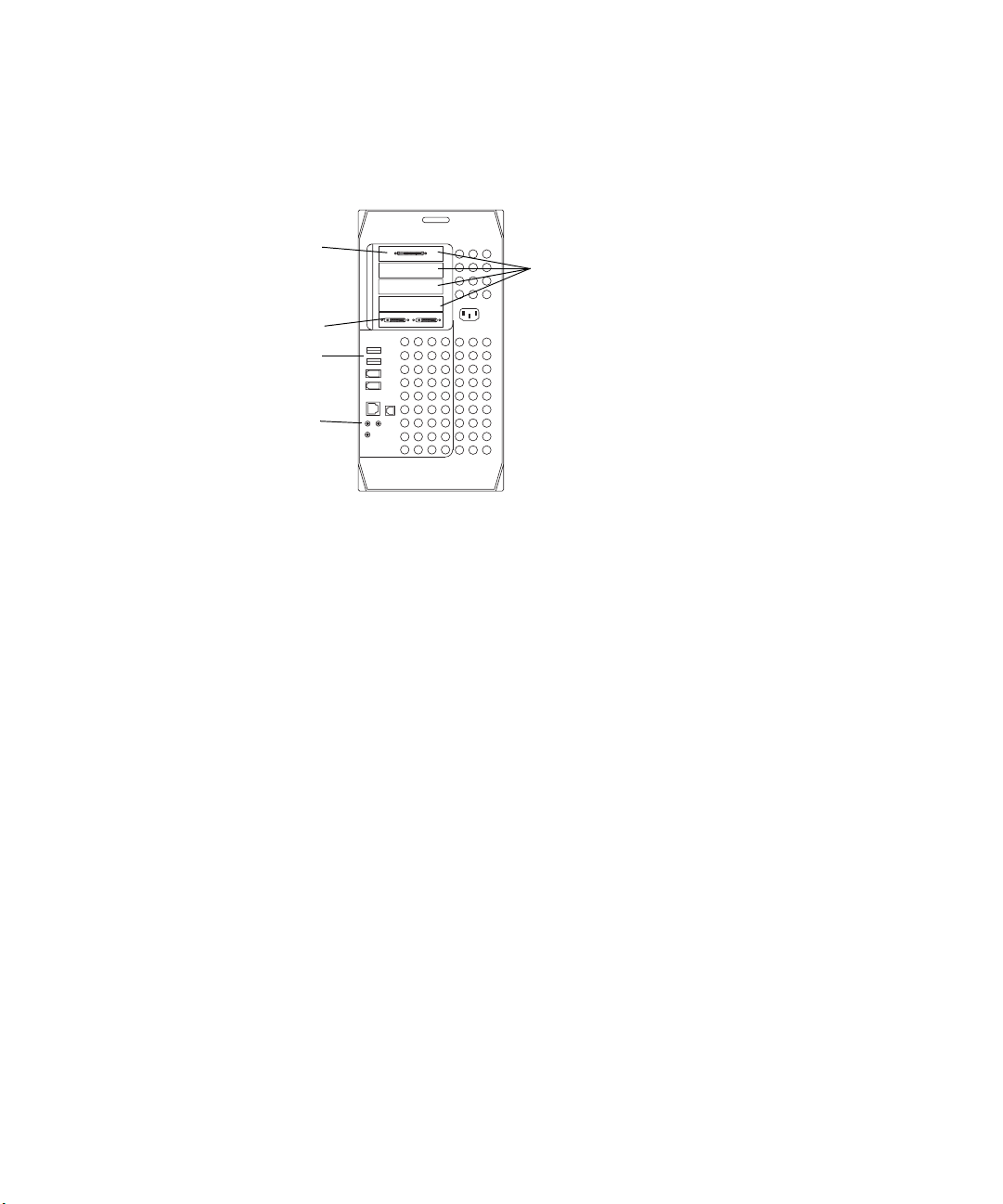
5
Slot 5 Host
interface board
Slot 1 Apple
graphics board
USB ports
Audio connectors
G4 platform
Optional location of digital media portion
3
2
1
Figure 1 Rear View of G4
of the Avid Meridien III video subsystem
when no Avid PCI Extender is used.
Avid System Components
c
n
n
Avid supports a 4-foot (1.2-meter) flat ribbon cable for use between the
G4 platform and the Avid PCI Extender. Using a longer cable is not
supported and can cause unstable data transfers.
See the Apple user’s guide that ships with the system for the exact locations
of device connectors on the rear panel.
As of this writing all systems ship with a minimum memory requirement
of 512 MB for all Avid applications. Always check the release notes that
came with your system for changes in the memory requirements and
memory configuration.
If you need to increase the system memory in your Avid system, contact
your support provider or use your Apple user’s guide that ships with the
system.
23
Page 24
Chapter 1 Hardware Overview
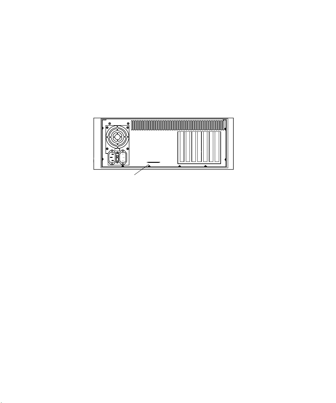
Avid PCI Extender
The Avid system uses a PCI expansion interface board to connect the G4
platform to the optional Avid PCI Extender (see Figure 2). The Avid PCI
Extender is only needed if you want to use SCSI and Fibre Channel
devices in the same system. It contains a set of Meridien PCI boards that
allow you to input and output data from a variety of sources.
Avid extender interface connector
Figure 2 Avid PCI Extender Rear View
c
Avid supports a 4-foot (1.2-meter) flat ribbon cable for use between the
G4 platform and the Avid PCI Extender. Using a longer cable is not
supported and can cause unstable data transfers.
Slots
17through
24
Page 25

Avid System Components
Avid System Board Locations
Table 1 lists the location of each board in the Avid system.
Table 1 Avid System Board Location
Avid System Boards Location
Apple graphics board G4
Host interface board G4
Avid extender interface
SCSI UL3D/160 dual-channel LVD board (UL3D)(optional) Avid PCI Extender or G4
Fibre Channel controller board (optional) Avid PCI Extender or G4
Meridien III digital media board set (Avid Composer Products)
Meridien III-U digital media board set (Symphony)
Meridien 3D effects board (Z6 board) Avid PCI Extender or G4
Meridien
Meridien
Meridien serial digital I/O board (attached to the video I/O board) Meridien I/O box
Meridien eight-channel audio interface board Meridien I/O box
Meridien two-channel audio I/O board Meridien I/O box
display controller board (single-head) Avid PCI Extender or G4
video I/O board Meridien I/O box
Avid PCI Extender
Avid PCI Extender or G4
a
a. Built into the system board of the Avid PCI Extender.
25
Page 26

Chapter 1 Hardware Overview
Avid Extender Interface
The Avid extender interface is built into the system board of the Avid PCI
Extender and connects the Avid PCI Extender to the G4 platform using a
flat ribbon cable no longer than 4 feet (1.2 meters) in length.
SCSI UL3D/160 Dual-Channel LVD Board
The optional SCSI UL3D/160 dual-channel LVD board (UL3D) is used
with all Avid rS MediaDrives and the Avid MediaDock
system and other Avid supported storage devices (see “Supported Storage”
on page 31 for actual drive information).
Fibre Channel Controller Board
You can have one of two types of optional Fibre Channel controller boards:
• The 2-Gb optical Fibre Channel controller board allows the system to
use Avid Unity
™
MediaNetwork or an optical standalone Fibre
Channel storage subsystem.
• The 2-Gb copper Fibre Channel controller board is available for an
existing copper standalone Fibre Channel storage subsystem. This
board is not supported for Avid Unity MediaNetwork.
Meridien III (or III-U) Digital Media Board Set
The Meridien III or III-U digital media board set is a PCI board and a
daughter board. Depending on the system you order, the board set can
provide deep defocus, compression and decompression functions, color
correction circuitry, the use of 24p, and Ultimatte
by the dongle. The board set also interfaces the 3D effects board if present,
and acts as an interface to the Meridien I/O box.
™
LVD storage
®
functionality controlled
Meridien 3D Effects Board
The system uses optional 3D video effects to enhance video production.
3D effects are supplied by a Z6 3D effects board. The board provides 3D
effects and uses one PCI slot. The 3D effects board connects to the digital
media board using an over-the-top connector. The 1394 connection on this
board is not functional.
26
Page 27
Meridien Display Controller Board
The system uses a single-head Meridien display controller board (display
controller board) to support the Edit monitor. The monitor is normally
supplied with the system.
Avid System Components
n
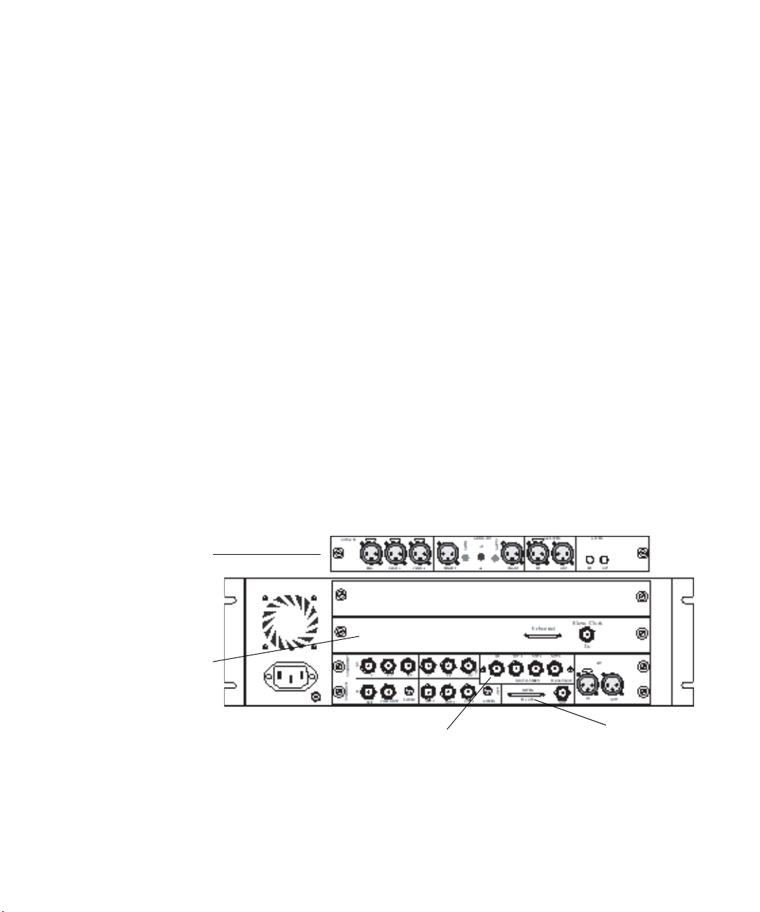
Meridien I/O Box
n
Two-channel
audio I/O board
The Bin monitor is controlled by the graphics board in the G4 platform,
and is not part of the Meridien I/O board set. Information on how to
connect the Client monitor is located in “Connecting a Client Monitor” on
page 74.
The system uses the Meridien I/O boards in the Meridien I/O box to
support video and audio. The following sections explain the functions of
each board.
Depending upon the system you purchase, you will have either the twochannel or eight-channel audio board. You can identify the boards in your
Meridien I/O box by looking at the back of the Meridien I/O box (see
Figure 3).
Eight-channel
audio interface
board
Serial digital I/O board
Figure 3 Meridien I/O Box Rear View
Video I/O board
27
Page 28

Chapter 1 Hardware Overview
Meridien Video I/O Board
Each system uses a video I/O board. The video I/O board has the following
features:
• Provides a parallel digital interface between the digital media board
and the analog I/O.
• Digitizes one channel of composite, component (Y, R-Y, B-Y), or
S-Video.
• Converts digital output from the digital media board to an analog
output signal for composite (three outputs), component, and S-Video.
• Acts as a baseboard for the serial digital I/O (SDI) board.
• Provides a genlock capability to allow the video to be locked to an
external source such as house sync or to a black burst generator
(BBGen).
• Provides an audio slave clock to lock incoming audio to incoming
video.
Meridien Serial Digital I/O Board
The SDI board provides physical inputs and outputs between the video I/O
board and a serial digital device.
Meridien Eight-Channel Audio Interface Board
An eight-channel audio interface board that links the system to a separate
eight-channel audio I/O device (Digidesign
device provides connections for up to eight channels of digital audio or
eight channels of analog audio.
Meridien Two-Channel Audio I/O Board
A two-channel audio I/O board provides connections for two channels of
digital audio, two channels of analog audio, and a microphone input. This
is a standalone board.
28
®
888 I/O™). The audio I/O
Page 29

Universal Serial Bus Devices
The connector panel on the G4 platform has two Universal Serial Bus
(USB) ports (see Figure 1). Avid connects a USB keyboard to one USB
port and a 7-port USB hub to the other USB port.
The following list shows the devices that attach to the 7-port USB hub:
• USB floppy drive
• USB-to-serial adapter
• USB-to-MIDI converter
• USB application key (dongle)
The USB mouse connects to the USB keyboard.
Universal Serial Bus Devices
n
n
The software drivers for the USB devices ship separately from the Avid
CD-ROM installer. You should keep the USB device drivers in a dry, staticfree location. If you need to rebuild the Avid system disk, you must install
the USB device drivers before you install the Avid software. See the release
notes for your specific Avid software for more information.
If you have USB dongles (other than the Avid dongle) that need to be
attached to your system, you should attach them to the remaining ports on
the 7-port USB hub.
29
Page 30

Chapter 1 Hardware Overview
Supported Devices
This section lists the supported devices for Avid systems and the Meridien
hardware.
Supported Monitors
The following Avid monitors are supported in Avid systems:
• Edit monitors — 22-inch, high-resolution Mitsubishi
• Bin monitors — 22-inch, high-resolution Mitsubishi
• A Client monitor capable of composite, YUV, serial digital, or SVHS
The following Apple monitors are supported in Avid systems:
• Edit monitors — 15-inch flat panel, 15-inch studio display,
17-inch studio display
• Bin monitors — 15-inch flat panel, 15-inch studio display,
17-inch studio display, 21-inch studio display, 22-inch cinema display
(flat panel)
®
30
n
c
The Meridien hardware with Avid systems does not support 640 x 480
monitors or setting a high-resolution monitor for the edit display to
640 x 480.
You must select the proper resolutions and number of colors for each
monitor as explained in “Configuring the Avid System” on page 58, or
your Edit monitor might appear black and your Avid software might
not function properly.
Page 31

Supported Storage
There are three types of external storage options available for your Avid
system:
• Standalone Fibre Channel
• SCSI UL3D/160 LVD board (LVD drives only)
• Avid Unity MediaNetwork
Supported Devices
n
Standalone Fibre Channel
SCSI UL3D/160 LVD Board
As drive size and drive speed improve, some Fibre Channel devices,
MediaDrives, and LVD shuttles will be available for use, while some might
be discontinued. Contact your Avid Sales and Product information line at
800-949-2843 for more product information.
The shipping standalone Fibre Channel system uses a 2-Gb optical Fibre
Channel controller board (see “Fibre Channel Controller Board” on
page 26) and a Fibre Channel disk enclosure that contains up to 14 drives.
The SCSI LVD board associated with Avid systems is the SCSI UL3D/160
dual-channel LVD. It can be used by all Avid systems (see “SCSI
UL3D/160 Dual-Channel LVD Board” on page 26).
The system supports four types of SCSI storage:
• All rS LVD MediaDrives available in rack and stack enclosures
• The MediaDock LVD storage system
• The MediaDock 2+ LVD storage system
• The MediaRAID 8 IDE storage system
31
Page 32

Chapter 1 Hardware Overview
Avid Unity MediaNetwork
The Avid Unity MediaNetwork server and storage subsystem use Fibre
Channel storage components to provide the shared storage environment for
a number of MediaNetwork clients.
For more information about Avid Unity MediaNetwork, see the
documentation that ships with Avid’s Workgroup solutions and Avid Unity
MediaNetwork.
Audio and Video Equipment
The system supports the following add-on hardware for advanced audio
and video input and output capabilities. The system you purchase
determines whether the hardware is standard with your system or can be
added as an option.
Audio I/O Device
The system supports eight channels of audio using an eight-channel audio
I/O device. The device allows you to connect up to eight channels of
professional-quality audio equipment, such as mixers and audio outputs
from high-end video decks.
Black Burst Generator
A black burst generator creates a common reference signal that is used by
many of the components external to the system to synchronize audio and
video signals when using multiple video decks.
32
Page 33
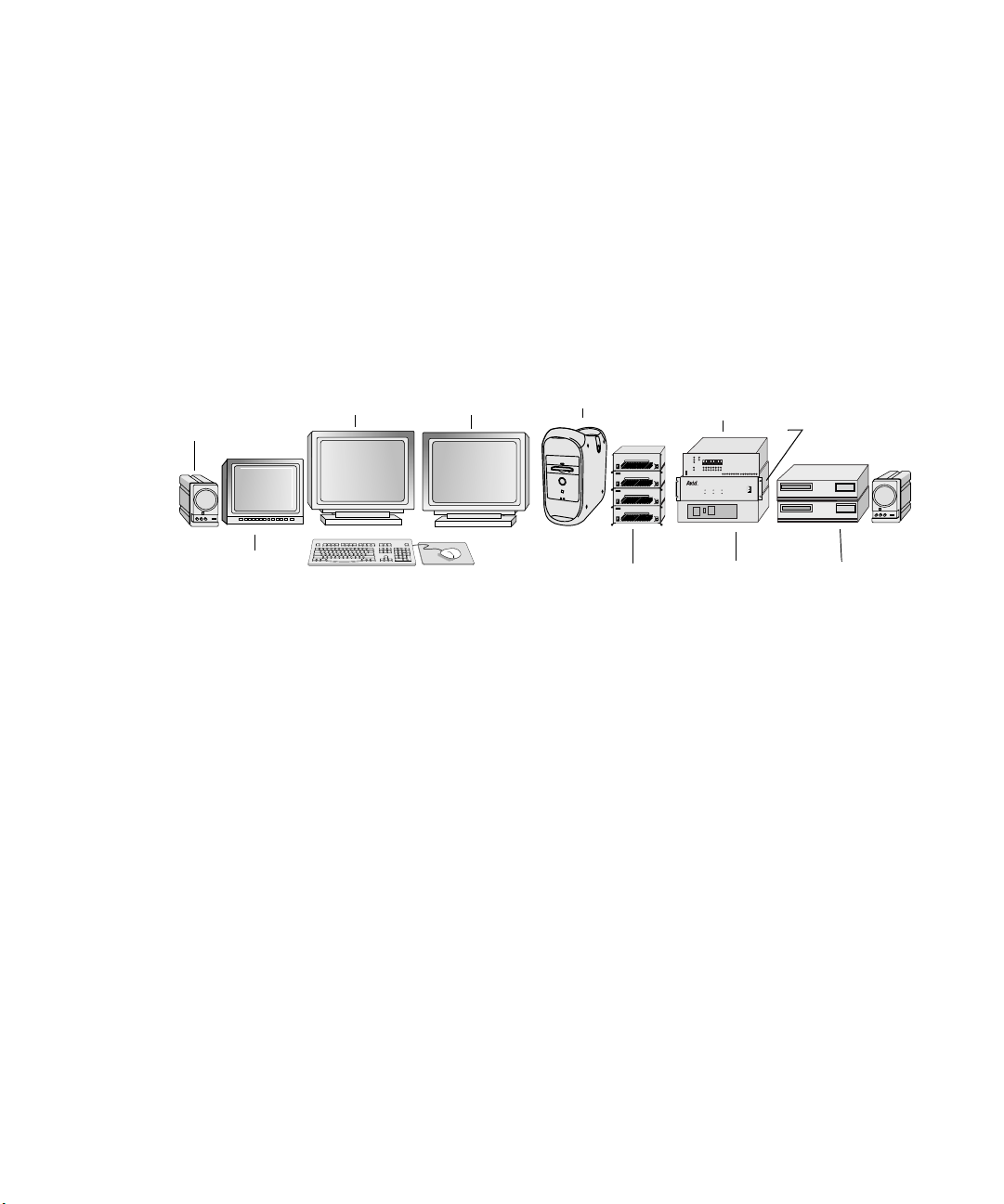
Typical System Layout
As you set up the system, you need to arrange the various components to
avoid exceeding the lengths of the cables that are provided with the system.
Yo u must place the Avid PCI Extender close to the G4 platform.
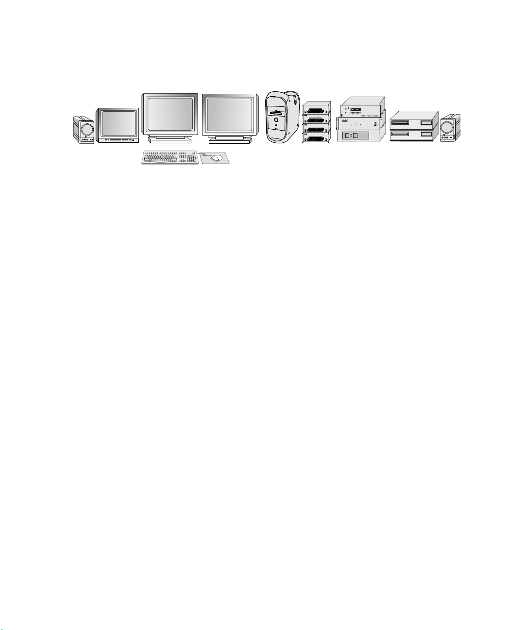
Figure 4 shows a sample layout for an Avid system using the G4 platform,
Avid PCI Extender, Meridien I/O box, monitors, speakers, Avid Fibre
Channel or SCSI drives, video decks, and an audio I/O device.
Typical System Layout
Speaker
Client monitor
Bin monitor
Edit monitor
Fibre Channel or SCSI drives
Figure 4 Avid System Layout
G4
Audio I/O
AUDIO SYNC
kHz
VIDEO SYNC
O
l
PULL DOWN
POWER
Meridien I/O
box
Video decks
device
rS18 plus
3
rS18 plus
2
rS18 plus
rS18 plus
44.1 kHz
48
1
0
Avid PCI Extender
33
Page 34

Chapter 1 Hardware Overview
34
Page 35

Chapter 2
Setting Up the System Hardware
This chapter explains how to connect the different parts of your Avid
system. You might not have all of the equipment mentioned in this chapter,
depending upon the type of system you purchased.
This chapter contains the following sections:
• Before You Begin
• Checking the Kit Contents
• Installing the SCSI or Fibre Channel Board
• Arranging the Components
• Assembling the System
• Connecting the Meridien I/O Box
• Connecting the Monitors
• Connecting USB Devices
• Connecting the Storage Subsystem
Page 36

Chapter 2 Setting Up the System Hardware
Before You Begin
Before you begin installing the Avid system, do the following:
• Unpack all the boxes that came with the hardware kit.
• Check the contents of the hardware kit against the packing list to
confirm you have received all the parts.
• Determine if you need to install a SCSI or Fibre Channel board.
• Position the hardware components.
Checking the Kit Contents
Unpack and check the contents of the kit to ensure you have all the
necessary parts. The kit contains as standard hardware components:
• A supported G4 platform with a USB keyboard, USB mouse, and a
USB application key (dongle)
36
n
• An optional Avid PCI Extender
• A separate SCSI board or Fibre Channel board
• USB devices such as a 7-port hub, a floppy drive, a USB-to-serial
adapter, and a USB-to-MIDI converter
• Two monitors for an Avid system, 22 inches in size
Avid Xpress systems include one high-resolution 22-inch monitor in the
standard system configuration. Additional monitors are optional.
• Two speakers
• Peripheral boards for audio, video, compression, and SCSI
acceleration (installed in the expansion chassis)
• Some type of storage subsystem (Avid MediaDrives,
MediaDock LVD, or other supported storage)
• Cables to connect the G4 platform and the audio equipment, video
equipment, monitors, and MediaDrives
Page 37

Installing the SCSI or Fibre Channel Board
Your system might also include as standard or optional hardware
components:
• Cables to connect the G4 platform and the optional Avid PCI Extender
• An eight-channel audio interface board with an eight-channel audio
I/O device
• A standalone Fibre Channel storage subsystem
• A black burst generator
Installing the SCSI or Fibre Channel Board
If you received a SCSI board or a Fibre Channel board that is not installed
in the system, you should refer to Appendix A and follow the instructions
to install the board before you proceed any further.
Arranging the Components
Start arranging the components in the Avid system by placing the
monitors, keyboard, mouse, and speakers in positions that are comfortable
for viewing and operating the system (see Figure 5). The Meridien I/O box
and the audio I/O device must be placed close to each other. They are
connected by cables that are 2 feet long.
Place the G4 platform, the optional Avid PCI Extender, and the SCSI
drives (or the Fibre Channel drives) close together. The G4 platform and
the Avid PCI Extender connect using up to a 4-foot (1.2-meter) cable.
Position the remaining components, such as video decks, additional audio
I/O devices, and video interface hardware in locations that are easily
accessible.
37
Page 38
Chapter 2 Setting Up the System Hardware
Figure 5 Arranging the G4 and Avid PCI Extender System
Assembling the System
All systems shipped directly from Avid have most of the PCI boards
already installed in the G4 or the optional Avid PCI Extender (the SCSI or
Fibre Channel boards might not be installed). The Avid extender interface
is already installed in the system board of the Avid PCI Extender, and the
Avid PCI host interface board is installed in the G4 platform. The video
and audio boards are installed in the Meridien I/O box.
rS18 plus
3
rS18 plus
2
rS18 plus
1
rS18 plus
0
O
l
PULL DOWN
44.1 kHz
AUDIO SYNC
kHz
POWER
48
VIDEO SYNC
38
n
c
In this section, connections to the Avid PCI boards are shown to the boards
only, not installed in the Avid PCI Extender.
Before you begin assembling your Avid system, check the release notes
that came with the system to make sure there are no changes,
additions, or deletions to the following procedures.
Page 39

Assembling the System
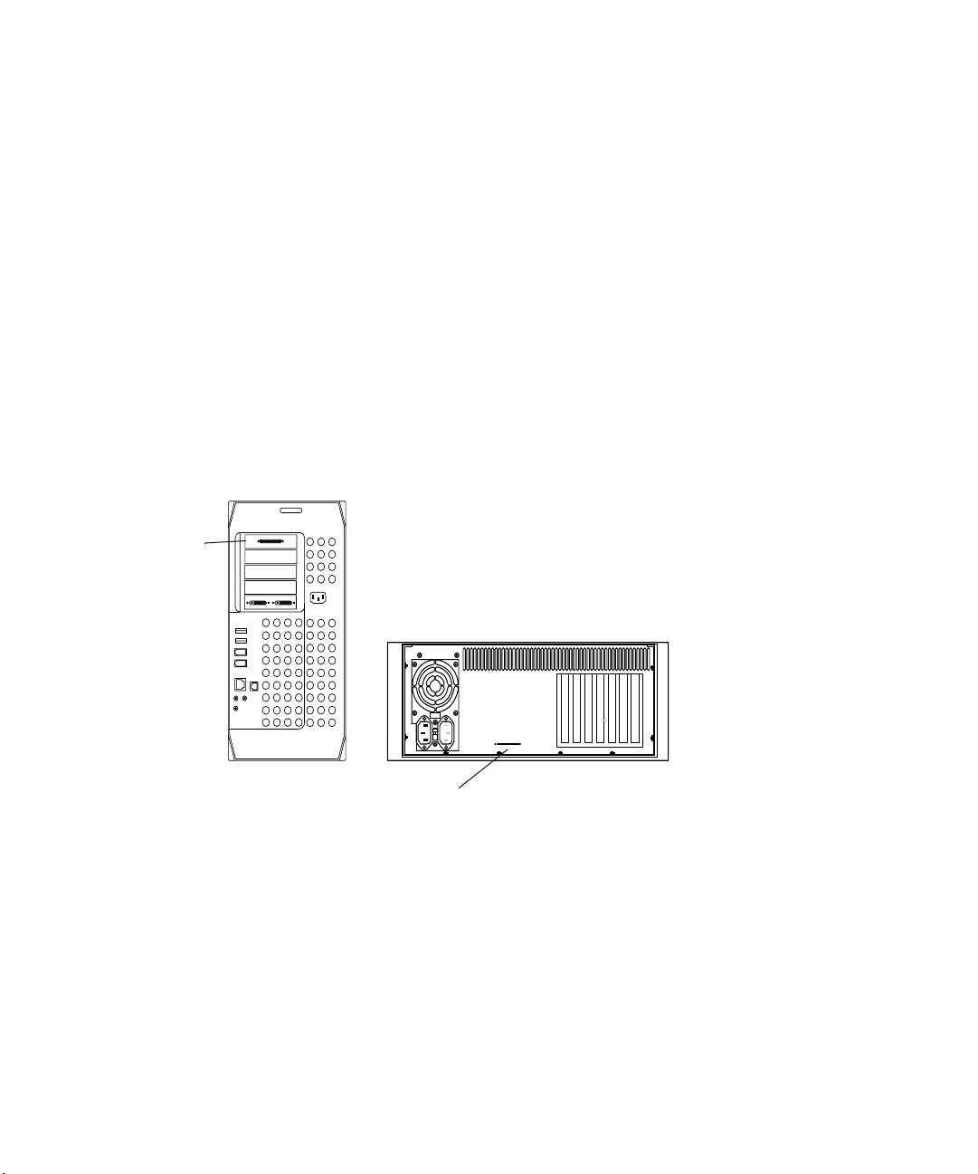
Checking the Voltage Switch on the Avid PCI Extender
The shipping Avid PCI Extender contains a switch-selectable power
supply. Make sure the voltage setting at the rear of the system is set
properly for your area.
Setting the Voltage Switch
The voltage switch is located at the rear of the system between the two
power sockets (see Figure 6). To set the voltage switch slide the switch to
show 115 for voltages in the 100 to 120 V ac range, or to show 230 for
voltages in the 200 to 240 V ac range.
Voltage
switch
Figure 6 Setting the Avid PCI Extender Voltage Switch
39
Page 40
Chapter 2 Setting Up the System Hardware
Connecting the G4 Platform and the Avid PCI Extender
The G4 platform and the optional Avid PCI Extender are connected by a
flat, gray, ribbon cable.
To connect the G4 platform and the Avid PCI Extender:
1. Attach one end of the Avid PCI Extender cable to the board in
slot 5 of the G4 platform (see Figure 7).
2. Attach the other end of the Avid PCI Extender cable to the Avid
extender interface connector of the Avid PCI Extender.
3. Plug the power cords of both the G4 platform and the Avid PCI
Extender into a power strip.
G4 platform
Slot 5
5
4
3
2
1
Avid PCI Extender
Avid PCI Extender
uses a 4-foot (1.2-meter)
cable.
Avid extender interface connector
Figure 7 Connecting the G4 Platform and the Avid PCI Extender
40
Page 41

Connecting the Meridien I/O Box
The Meridien I/O box is a standalone box that contains the audio and video
I/O boards. You connect video equipment to the Meridien I/O box and
audio equipment to the audio I/O device. The Meridien I/O box is
connected to the digital media board located in the Avid PCI Extender
using a 9.8-foot (3-meter) digital data cable.
To connect the Meridien I/O box:
1. Locate the 9.8-foot (3-meter) digital data cable. The ends of the digital
data cable are shown in Figure 8.
Figure 8 Digital Data Cable
Connecting the Meridien I/O Box
2. Connect one end of the digital data cable to the Meridien I/O box at the
system interface connector shown in Figure 9.
Meridien I/O box
8 channel
OUT 1 OUT 2 OUT 3IN
OUT
DIGITAL VIDEO
SYSTEM
OUT
IN / OUT
S-VIDEO
COMPONENT
COMPOSITE
IN
ININ
Y
R-Y B-Y
IN
S-VIDEO
COMPOSITE
REF
OUT 1
B-Y
Y
R-Y
OUT 3
OUT 2
Figure 9 Meridien I/O Box to System Cable Connection
Slave Clock
In
LTC
SLAVE CLOCK
IN
OUT
OUT
System interface connector
41
Page 42

Chapter 2 Setting Up the System Hardware
3. Locate the digital media board in the Avid PCI Extender (see
Figure 10). Connect the other end of the digital data cable to the
connector labeled M (main) on the digital media board.
Connection to Meridien I/O box
Digital media board
Connection C not used
Figure 10 Digital Media Board to Meridien I/O Box Cable
Connection
Connecting the Monitors
The Avid system comes with a high-resolution Bin monitor and a highresolution Edit monitor. The Bin monitor displays the Macintosh operating
system desktop, while the Edit monitor displays the Avid software editing
environment.
MC
42
c
You must select the proper resolutions and number of colors for each
monitor as explained in “Configuring the Avid System” on page 58, or
your Edit monitor might appear black and your Avid software might
not function properly.
Although you can set the monitors up anyway you want, Avid suggests that
the Bin monitor should be located to the left of the Edit monitor. This
allows you to maintain the proper two-screen display needed by the
operating system and the Avid system.
Page 43

Connecting the Monitors
5
Use the following instructions to connect the monitors to the correct
locations on the display controller board.
n
The monitors shown in the following sections might not be the monitors
you receive. If you use different monitors on your system, see the user’s
guide that accompanies the monitor to complete the monitor installation,
or contact the monitor reseller.
Connecting the Bin Monitor
To connect the Bin monitor using the VGA port:
1. Locate the Bin monitor cable (VGA cable). This cable has a standard
VGA style connector at both ends.
2. Attach one connector to the VGA graphics port on the G4 platform
(see Figure 11).
G4 platform
VGA graphics port
3
2
1
Figure 11 Bin Monitor to Graphics Port
n
You can also use the Apple-supplied DVI to VGA adapter and use the DVI
graphics port.
43
Page 44

Chapter 2 Setting Up the System Hardware
3. Attach the other end of the VGA cable to the VGA connector of the
selected signal source input connector on the Bin monitor.
4. Attach the ac power cord to the ac power connector on the back of the
monitor.
5. Plug the ac power cord into a power strip.
Connecting the Edit Monitor
To connect the Edit monitor:
1. Locate the Edit monitor cable (VGA connectors at both ends) in the
hardware kit.
2. Locate the edit display controller board in the Avid PCI Extender (see
Figure 12).
3. Attach one end of the Edit monitor cable to the VGA connector labeled
EDIT on the display controller board.
44
EDIT
Figure 12 Edit Monitor to Display Controller Connection
Display controller board
Monitor VGA cable
4. Attach the other end of the Edit monitor cable to the VGA input
connector on the Edit monitor.
5. Attach the ac power cord to the ac power connector on the back of the
monitor.
6. Plug the ac power cord into a power strip.
Page 45

Connecting the Monitors
n
When the system is started for the first time, you might need to adjust the
monitors that are attached to the display controller board. Controls to
adjust the monitor are part of a tilt-out panel below the monitor screen.
For information on using these controls, see the user’s guide included with
the monitor.
Connecting a Single Monitor in an Avid Xpress System
If you have a single-monitor Avid Xpress system, the monitor is used as
the Bin and Edit monitor.
To connect a single monitor in an Avid Xpress system you must:
1. Remove the Apple graphics board from the system.
n
To remove the Apple graphics board, follow the instructions in Appendix A.
2. Connect the single monitor to the Meridien display controller board as
if you were connecting the Edit monitor described in “Connecting the
Edit Monitor” on page 44.
With the Apple graphics board removed, the operating system sends boot
and console information, as well as video, to the Meridien display
controller board.
Connecting the Client Monitor
The Client monitor displays the playback in either NTSC or PAL format.
The Client monitor can be connected to an analog composite output, a
component output, or to the serial digital (SDI) output of the Meridien I/O
box. See “Connecting a Client Monitor” on page 74 for a description of
how to connect the Client monitor to the composite output.
45
Page 46

Chapter 2 Setting Up the System Hardware
Connecting USB Devices
The Avid system uses USB devices that connect to the two USB ports at
the rear of the G4 platform. Most of these devices have there own software
drivers that need to be installed before they can be used.
This section explains how to connect the USB devices, but does not
provide instructions for installing the software.
n
n
After you complete the physical installation of all devices explained in this
section, you should continue with Chapter 3. Chapter 3 explains how to
turn on the system and points to the release notes that contain the
instructions for installing the USB devices’ software and the Avid software.
You need to install drivers for all of the USB devices (except the USB hub,
dongle, and keyboard) prior to installing the Avid software.
This section explains how to connect the following USB devices:
• The USB mouse to the USB keyboard
• 7-port USB hub with the following attached devices:
- USB floppy drive
- USB-to-serial adapter
- USB-to-MIDI converter
- USB application key (dongle)
If more USB devices become available for use with the Avid system before
this guide is updated, or instructions change, release notes will be sent
with the devices to explain hardware and software installation.
46
Page 47

Connecting the Keyboard and Mouse
The USB keyboard devices provided with the G4 platform are the
keyboard and USB mouse.
To connect the USB keyboard devices:
1. Connect the USB mouse to the left or right USB connector on the
keyboard.
2. Attach the keyboard cable to one of the two USB ports at the rear of
the G4 platform (see Figure 13).
Connecting USB Devices
n
USB ports
Opening the CD/DVD Drive on the 1-GHz G4 Platform
Avid supplies a different keyboard that provides keycaps that map to
specific Avid functions. This keyboard does not allow you to open the
CD/DVD drive. See “Opening the CD/DVD Drive on the 1-GHz G4
Platform” on page 47 for instructions on opening the CD/DVD drive.
Keyboard connector
Figure 13 USB Port Connection
The 1-GHz G4 platform does not have a button to open the CD/DVD drive.
The standard way to open the CD/DVD drive is by pressing the Eject
button in the upper right corner of the Apple keyboard.
Problem — Avid supplies a different keyboard that provides keycaps that
map to specific Avid functions. This keyboard does not allow you to open
the CD/DVD drive with the same key as the Apple keyboard.
Solution — Press the F12 key on the Avid-supplied keyboard.
47
Page 48

Chapter 2 Setting Up the System Hardware
Connecting the USB Hub
The USB hub converts one USB port at the rear of the G4 platform into
seven USB ports. The USB hub kit (see Figure 14) contains a USB hub, a
power adapter, and a USB cable.
USB hub
n
n
The USB hub shown in the example might not be the actual USB hub you
receive. However, the example shown provides enough information to
allow you to properly connect whatever USB hub you receive.
The USB hub is supported only when it is powered by the ac converter.
DC connector
USB ports
Device connection
On/Off switch
Power connection
Device connector
Figure 14 USB Hub
AC connector
Power adapter
USB cable
USB connector
48
Page 49

Connecting USB Devices
The USB hub has the following rear connections:
• USB ports 1 through 7
• Device connection
• On/Off switch
• Power connection
To connect the USB hub (see Figure 14) to the G4 platform:
1. Connect the power adapter to the USB hub:
- Plug the dc connector of the power adapter into the power
connection at the rear of the USB hub.
- Plug the ac connector of the power adapter into a wall outlet or
power strip.
2. Connect the USB hub to the G4 platform using the USB cable:
- Plug the device connector of the USB cable into the device
connection at the rear of the USB hub.
- Plug the USB connector of the USB cable into one of the USB
ports at the rear of the G4 platform (see Figure 13).
3. Turn the power switch to the On position.
49
Page 50
Chapter 2 Setting Up the System Hardware
Connecting the USB Devices to the USB Hub
Once the USB hub is connected to the G4 platform, you can connect the
following USB devices to the USB hub:
• USB floppy drive
• USB-to-serial adapter
• USB-to-MIDI converter
• USB application key (dongle)
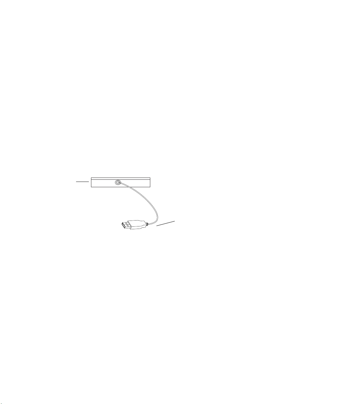
Connecting the USB Floppy Drive
Avid supplies a USB floppy drive (see Figure 15) with an attached cable
that connects to a USB port on the USB hub.
Floppy drive
50
n
USB connector
Figure 15 Connecting the USB Floppy Drive
To connect the floppy drive to a port on the USB hub:
t Connect the USB connector of the floppy-to-USB cable to a USB port at
the rear of the USB hub (see Figure 14 for a port location). The software
for the floppy drive is built into Mac OS X.
Power for the floppy drive comes through the floppy-to-USB cable.
Page 51
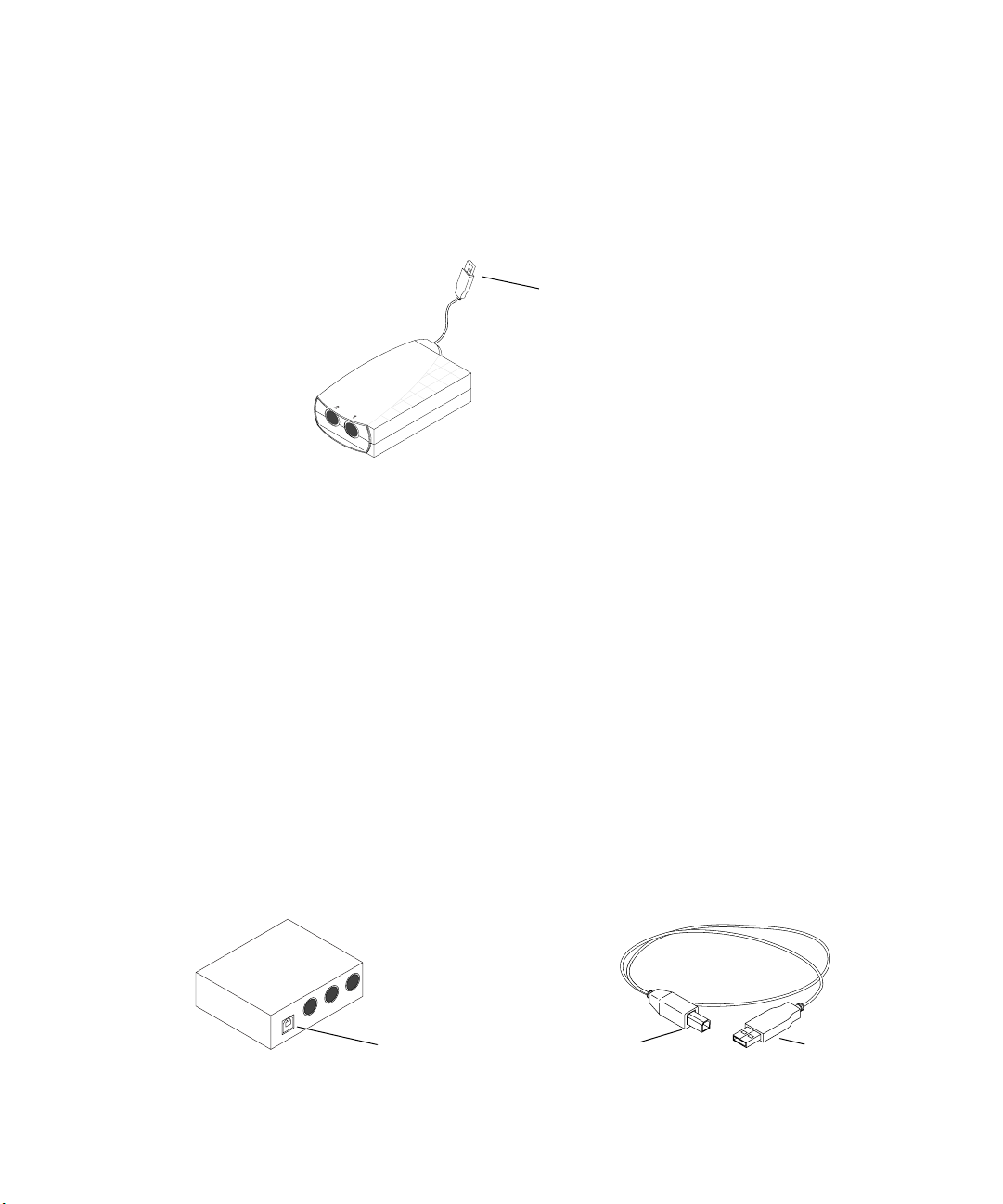
Connecting the USB-to-Serial Adapter
The USB-to-serial adapter (see Figure 16) connects to a USB port on the
USB hub.
Figure 16 USB-to-Serial Adapter
To connect the USB-to-serial adapter to the USB hub:
1. Plug the USB connector portion of the cable into a USB port at the rear
of the USB hub (see Figure 14 for a port location).
Connecting USB Devices
USB connector
2. Install the USB-to-serial adapter software, using the instructions
located on the USB-to-serial adapter CD-ROM.
Connecting the USB-to-MIDI Converter
The USB-to-MIDI converter and USB cable connects to a USB port on the
USB hub (see Figure 17). Only connect the USB-to-MIDI converter if you
are going to use it.
n
The USB-to-MIDI converter must be configured prior to use. See the
release notes for this information.
USB-to-MIDI converter
Device connector
Figure 17 Connecting the USB-to-MIDI Converter
USB cable
Device connector
USB connector
51
Page 52
Chapter 2 Setting Up the System Hardware
To connect the USB-to-MIDI converter to a port on the USB hub:
1. Find the MIDI converter USB cable.
2. Connect the device connector of the USB cable to the device connector
at the rear of the USB-to-MIDI converter.
3. Connect the USB connector of the USB cable to a USB port at the rear
of the USB hub (see Figure 14 for a port location).
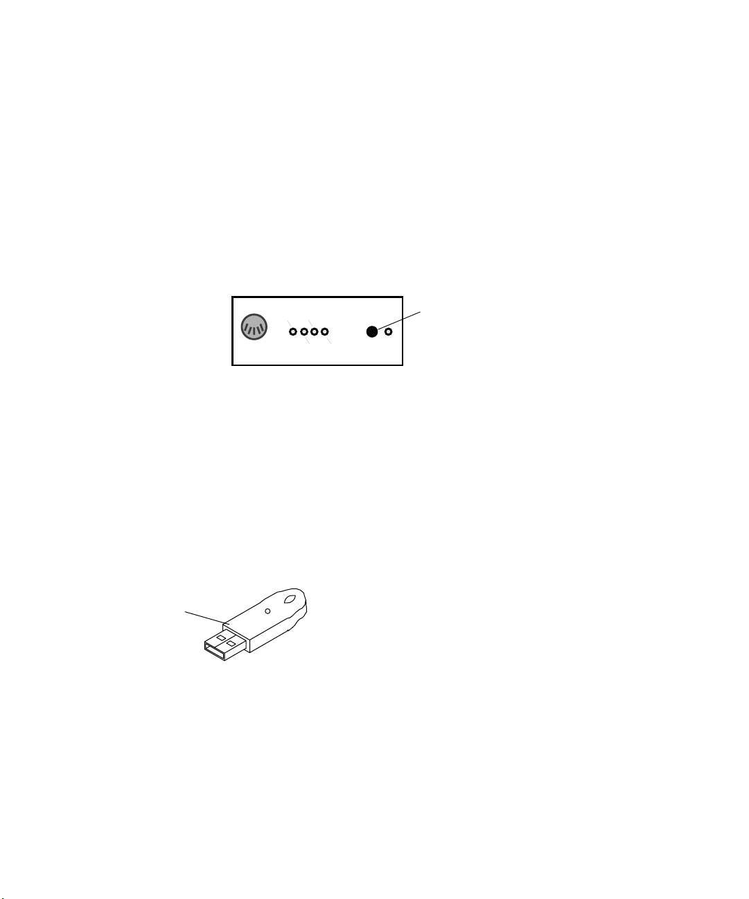
4. Push the USB/MIDI Thru button In to allow the device to act as a
USB-to-MIDI converter (see Figure 18).
IN A
IN A IN B
OUT A OUT B
USB-to-MIDI converter
Figure 18 USB-to-MIDI Converter Front Panel
n
Instructions for connecting the faders to the USB-to-MIDI converter can
be found in Chapter 5.
Connecting the USB Application Key
The application key, commonly referred to as a dongle (see Figure 19),
allows the Avid software to run on your system, and plugs into the USB
hub. Attach the dongle to any port on the USB hub.
USB dongle
Figure 19 USB Application Key (Dongle)
USB/
MIDI
Thru
Button (In position)
USB
52
c
Be careful that you do not lose the application key. Your Avid software
does not function without it. If you lose your application key, you must
purchase another key from Avid. Due to the replacement cost of the
application key, Avid recommends you insure the application key for
the full market cost of your system.
Page 53

Connecting the Storage Subsystem
Your Avid system supports the following three types of storage
subsystems:
• Avid MediaDrives (iS, iS Pro, and rS drives)
• Avid MediaDock LVD (a standalone SCSI subsystem)
• Fibre Channel storage subsystem
Manuals are provided for the Avid MediaDrives, Avid MediaDock LVD,
and Fibre Channel storage subsystem that contain detailed installation
instructions. Overviews of installations are provided in the following
sections.
Connecting the Storage Subsystem
n
If you received a SCSI board or a Fibre Channel board that is not installed
in the system, you should refer to Appendix A and follow the instructions to
install the board before you proceed any further.
Avid MediaDrives
You might have one or more types of Avid drives for storing the media and
other data associated with video and audio projects. The supported drives
can be found in “Supported Storage” on page 31.
You connect the drives to the SCSI LVD board. To identify the SCSI board
in your system, look at the back of the G4 platform or the back of the Avid
PCI Extender (see Figure 20).
n
The SCSI cable and the cable between the digital media board and
Meridien I/O box use the same type of connector. Make sure you connect
the SCSI cables to the proper connector.
53
Page 54
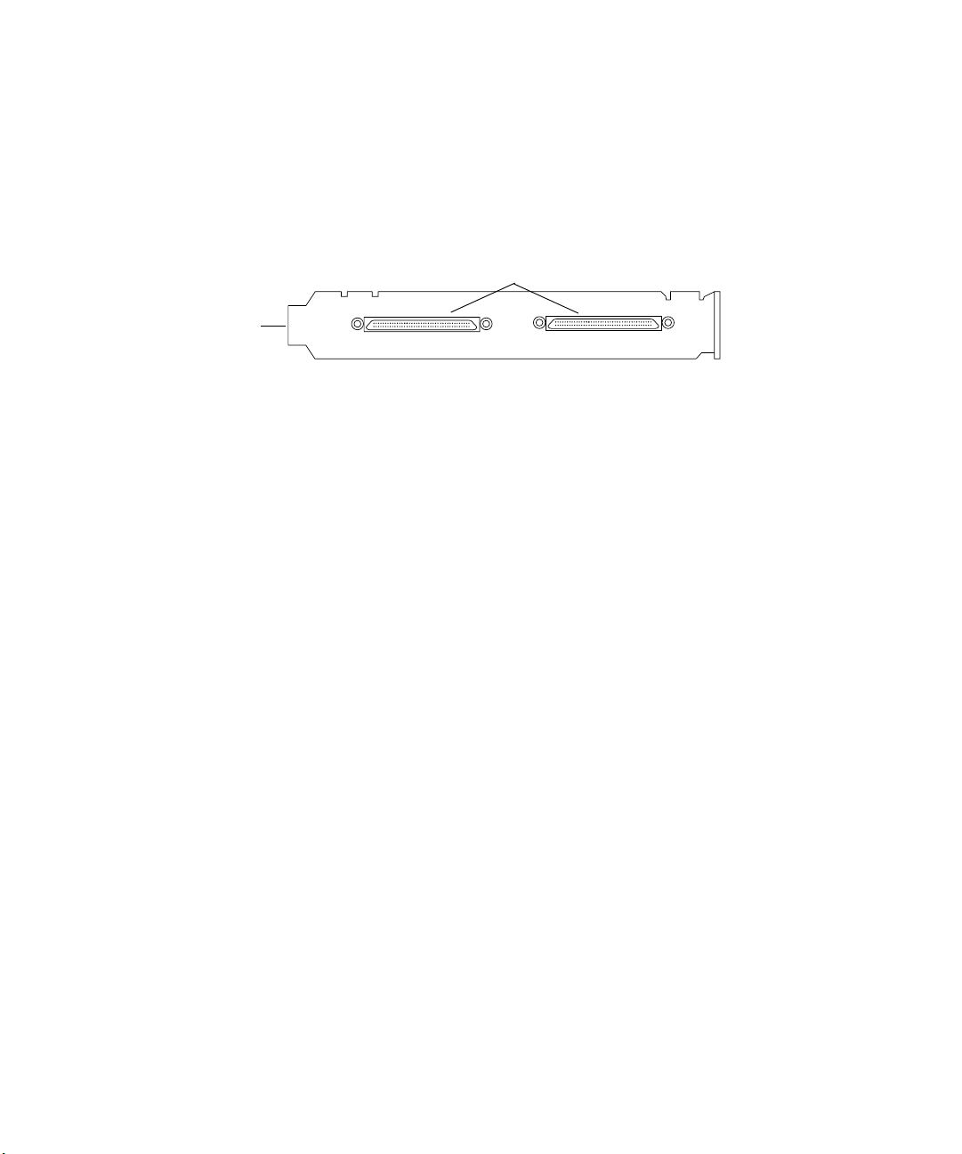
Chapter 2 Setting Up the System Hardware
c
SCSI LVD board
You should never connect or disconnect drives or terminators with the
system or drives on. See the drive manual that shipped with your
drives and the SCSI LVD Release Notes for detailed information on
how to connect drives to the new SCSI LVD board.
Figure 20 SCSI Cable to SCSI Board Connection
If you have more than one drive, you might want to stack the drives so they
take up a minimal amount of desk space, and arrange the drives in two
separate stacks (one stack for each connector).
Avid MediaDock LVD
You might have an Avid MediaDock LVD storage system that you need to
connect to the SCSI LVD board. To identify the SCSI LVD board in your
system, look at the back of the G4 platform or the back of the Avid PCI
Extender (see Figure 20). The supported drives available in the Avid
MediaDock LVD can be found in “Supported Storage” on page 31.
Very high-density interconnect connectors
Channel 1 Channel 2
54
c
You should never connect or disconnect drives or terminators with the
system or drives on. See the Avid MediaDock LVD Setup and User’s
Guide that shipped with your MediaDock LVD and the SCSI LVD
Release Notes for detailed information on how to connect the
MediaDock LVD to the SCSI LVD board.
Page 55

Fibre Channel Storage Subsystem
You might have a Fibre Channel storage subsystem that contains a 2-Gb
optical or copper Fibre Channel controller board. To identify the Fibre
Channel controller board in your system, look at the back of the G4
platform or the back of the Avid PCI Extender (see Figure 21). Installation
instructions ship with the Fibre Channel storage subsystem.
Fibre Channel optical
controller board
Fibre Channel copper
controller board
Connecting the Storage Subsystem
n
Figure 21 Fibre Channel Controller Boards
An adapter comes with the Fibre Channel copper controller board
allowing you to use copper cabling.
55
Page 56

Chapter 2 Setting Up the System Hardware
56
Page 57

Chapter 3
Turning On the System
Once the basic system is connected, you should turn on the system and
make sure your monitors are set up correctly.
This chapter contains the following sections:
• Turning On the System
• Configuring the Avid System
• Installing USB Device Software
• Installing the Avid Software
• Running the Diagnostics
• Diagnostic Utilities
Page 58

Chapter 3 Turning On the System
Turning On the System
Once you have the keyboard and mouse, monitors, disk subsystem,
Meridien I/O box, and application key (dongle) installed, you should turn
on the system to make sure it boots properly before you install the Avid
software and the remaining hardware.
To turn on the system:
1. Make sure all devices are properly plugged into a surge protector or
wall outlet.
2. Make sure the monitors are properly positioned: Bin monitor to the left
and Edit monitor to the right.
3. If you have the optional Avid PCI Extender, make sure it is turned on.
4. Make sure the Meridien I/O box and all drives are turned on.
5. Turn on the system.
If your system boots properly, continue with “Configuring the Avid
System” on page 58 to configure your monitors.
Configuring the Avid System
Avid systems come with an Edit monitor and a Bin monitor. These systems
have a specific configuration for the monitors to prevent the Macintosh
desktop from conflicting with the Edit monitor. You need to make sure the
Bin and Edit monitors are set up correctly.
Avid Xpress systems come with only an Edit monitor, and you can
purchase a Bin monitor as an option. These systems have a specific
configuration for the monitors to make sure the Macintosh desktop appears
on the Edit monitor. If you also connected a computer monitor, you need to
make sure both it and the Edit monitor are set up correctly and are set to
the same resolution.
58
Page 59

Configuring the Avid System
If your Avid system comes with two monitors, begin with “Setting Up the
Edit Monitor” on page 59, and continue with “Setting Up the Bin Monitor”
on page 61.
If your Avid system comes with a single monitor, begin with “Setting Up
the Bin Monitor” on page 61, and continue with “Installing the Avid
Software” on page 63.
c
Do not configure the monitors on the Avid system while the
Media Composer, Film Composer, or Avid Xpress software is running.
Setting Up the Edit Monitor
To configure the Edit monitor:
1. Click the System Preferences icon in the Dock (see Figure 22). The
System Preferences window opens (see Figure 23).
Dock
Figure 22 Dock
2. Click the Displays icon in the System Preferences window.
System Preferences icon
Displays icon
Figure 23 System Preferences Window
59
Page 60

Chapter 3 Turning On the System
n
The Edit monitor’s Display window opens on the right monitor if you have
two monitors (see Figure 24).
Figure 24 Edit Monitor’s Display Window
3. Click the Colors pop-up menu, and select Millions.
4. Select 1024 x 768 in the Resolutions list box. Click the Refresh Rate
pop-up menu, and select 75 Hertz. If you need to use a different
resolution, select a resolution from the Resolutions list box. These are
resolutions that are compatible between the video board and the
monitor.
60
c
5. Click Confirm in the dialog box that opens.
If you are using a Bin and Edit monitor, they must both be set to the
same resolution to work properly.
Page 61

Setting Up the Bin Monitor
Configuring the Avid System
n
Close
The Bin monitor’s Display window opens on the left monitor if you have
two monitors (see Figure 25).
Figure 25 Bin Monitor’s Display Window
To configure the Bin monitor:
1. Click the Colors pop-up menu, and select Millions.
c
2. Select 1024 x 768 in the Resolutions list box. Click the Refresh Rate
pop-up menu, and select 75 Hertz. If you need to use a different
resolution, select a resolution from the Resolutions list box. These are
resolutions that are compatible between the video board and the
monitor.
3. If you have only one monitor click the Close button. If you have two
monitors continue with “Arranging the Monitors and Desktop” on
page 62.
If you are using a Bin and Edit monitor, they must both be set to the
same resolution to work properly.
61
Page 62

Chapter 3 Turning On the System
Arranging the Monitors and Desktop
If you have both an Edit monitor and a Bin monitor connected to the Avid
system, you need to arrange the monitors to match their physical locations
in the system layout. You also need to set the Bin monitor as the startup
monitor.
To arrange the positions of the monitors and configure the desktop
and startup monitor:
1. Click the Arrangement tab in the Bin monitor’s Display window (see
Figure 26).
Close
Click one
of these monitors.
Menu bar
Figure 26 Arranging Monitors
2. Click one of the monitors and a red box opens on the monitor that
equates to the monitor you clicked (see Figure 26).
3. If the monitor positions on the window are reversed from their physical
positions, click one of the monitors and drag it to the correct position.
4. Click the Menu bar and drag it to the Bin monitor, if it is not already
there (see Figure 26). This places the startup screen on the Bin
monitor.
5. Click the Close button.
62
Page 63

Installing USB Device Software
You must install the USB device software prior to installing and executing
the Avid software. Locate the instructions that shipped with the USB
devices and install the software at this time.
Installing USB Device Software
n
See the release notes that are specific to your system for details on software
installation.
Installing the Avid Software
After configuring your monitors and installing USB device software, you
are ready to install the Avid software. To install the software, use the
application CD-ROM that shipped with your system.
n
Once you install the software, you can run Avid System Test Pro to test the
Meridien I/O board set and the Meridien I/O box. You can also run System
Manager to test Avid storage devices. These applications use the drivers
from the Avid software.
Running the Diagnostics
Avid diagnostics, Avid System Test Pro, is a set of utilities that test the
peripheral boards in the Avid system. The diagnostics are in the
Applications/Utilities/AvidSystemTest directory on your system drive.
When you double-click the Avid System Test Pro icon, a window opens
that allows you to select Board Diagnostics to test the peripheral boards
and any attached daughter boards. Appendix B explains how to run board
diagnostics. You can also obtain Help to run board diagnostics by selecting
Help > type of Help.
63
Page 64

Chapter 3 Turning On the System
Diagnostic Utilities
There are two other major software utilities available:
• Storage Manager allows you to:
- Select and create partitions.
- Create striped groups.
- Erase partitions.
- Perform hard drive surface tests.
n
n
n
The Storage Manager application and information on using Storage
Manager can be found in the Applications/Utilities/AvidStorageManager
directory on your system drive. You can also find Storage Manager on the
Avid online Knowledge Center at www.avid.com/support.
• DiskWarrior
you to rebuild your disk directory using the data recovered from the
original directory. By doing this you can recover files and folders that
you thought were lost. Your disk must be a Mac OS Standard (HFS) or
Mac OS Extended (HFS Plus) disk.
Avid ships the DiskWarrior CD-ROM that contains the application and the
manual that explains how to use the DiskWarrior software.
You should always check the release notes that ship with your system to see
if there have been any updates that relate to the diagnostic utility guides.
Drive striping and resolutions information can be found on the Avid online
Knowledge Center at www.avid.com/support.
®
specializes in eliminating directory errors by allowing
64
Page 65

Chapter 4
Connecting Audio and Video Equipment
This chapter describes how to connect audio and video equipment to the
audio and video boards in the Avid system. Configurations can be a simple
single-deck configuration or multiple-deck configurations with mixers and
an audio interface.
This chapter contains the following sections:
• Video Decks
• Configuration Notes
• Identifying Audio and Video Boards
• Meridien I/O Box Connectors
• Meridien I/O Box Indicators
• Connecting a Client Monitor
• Synchronizing Audio and Video Equipment
• Controlling a Video Deck
• Connecting Audio Equipment
• Connecting the Video Input/Output Board to Decks
• Connecting a Video Server
Page 66

Chapter 4 Connecting Audio and Video Equipment
Video Decks
The Avid system supports video decks from a number of different
manufacturers. These decks can be controlled directly by the system as
explained in this chapter.
The following sections describe how to connect the audio, video, and
control cabling that might be necessary to control your video deck. You
should select the sections that are appropriate for your system and
components.
Configuration Notes
The following list provides some general configuration notes that apply to
many of the configurations covered in this guide:
• You can have only one audio interface board in the Meridien I/O box at
one time.
66
• If you are not using the passthrough feature on your video deck to pass
the video signal to other devices, make sure you terminate the
passthrough connection with a 75-Ω terminator. This might be done
with a switch you need to turn on, or you might need to install 75-Ω
terminators on the open passthrough connectors.
• If you are using speakers without internal audio amplifiers, you will
need to connect an external audio amplifier between the audio source
and the speakers.
• The figures in this guide depicting the rear panels of the decks are
sample illustrations; the connectors on your deck might be in different
locations. Check the manual that came with your deck for the correct
connector names, locations, and functions.
Page 67
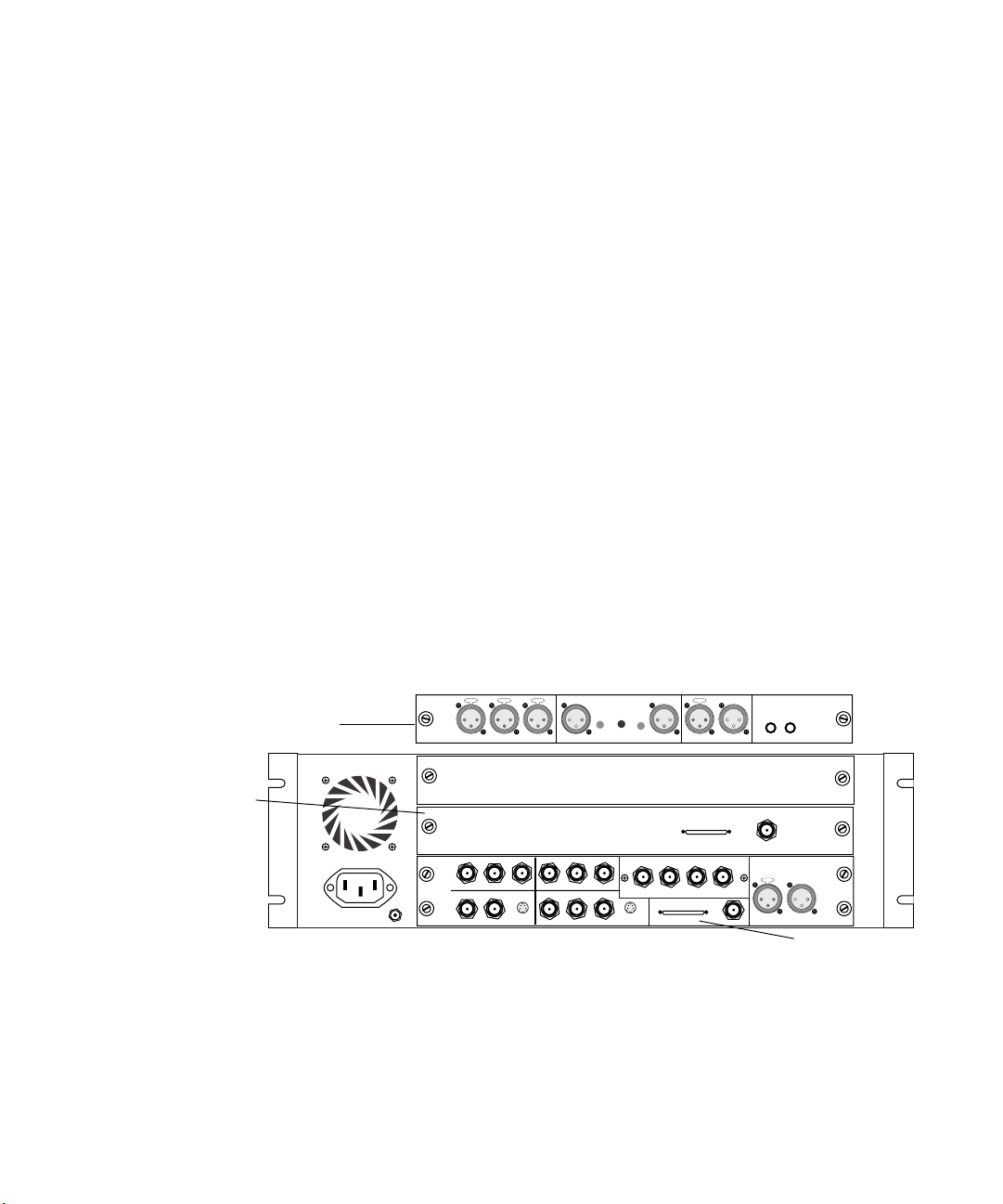
Identifying Audio and Video Boards
Avid systems with Meridien I/O hardware use the following
video I/O and audio I/O boards:
• Video I/O board — Provides analog and digital I/O connections for
video equipment, connects the Meridien I/O box to the digital media
board on the system, and provides locations for syncing equipment to
the Meridien I/O box.
• Eight-channel audio interface board — Connects digitally to the
eight-channel audio I/O device that provides eight channels of
analog I/O, AES/EBU I/O connections, and S/PDIF I/O
connections.
• Two-channel audio I/O board — Provides two channels of
analog I/O, AES/EBU I/O connections, S/PDIF I/O connections, and a
microphone input.
Depending upon the system you purchased, you will have either the twochannel or eight-channel audio board. You can identify the boards in your
Meridien I/O box by looking at the back of the Meridien I/O box (see
Figure 27).
Identifying Audio and Video Boards
Two-channel
audio I/O board
Eight-channel
audio interface
board
CHAN 1
AUDIO OUT
-10
GAIN 2
GAIN 1
+4
OUT
B-Y
R-Y
S-VIDEO
OUT 3
OUT 2
IN
CHAN 2
8 channel
OUT 1 OUT 2 OUT 3IN
DIGITAL VIDEO
SYSTEM
OUT
IN / OUT
AUDIO IN
COMPONENT
COMPOSITE
MIC CHAN 1
IN
ININ
Y
IN
REF
COMPOSITE
R-Y B-Y
S-VIDEO
CHAN 2
Y
OUT 1
Figure 27 Meridien I/O Board Identification
AES / EBU
OUT
SLAVE CLOCK
OUT
S / PDIF
IN
Slave Clock
In
LTC
IN
OUT
OUT
Video I/O board
67
Page 68
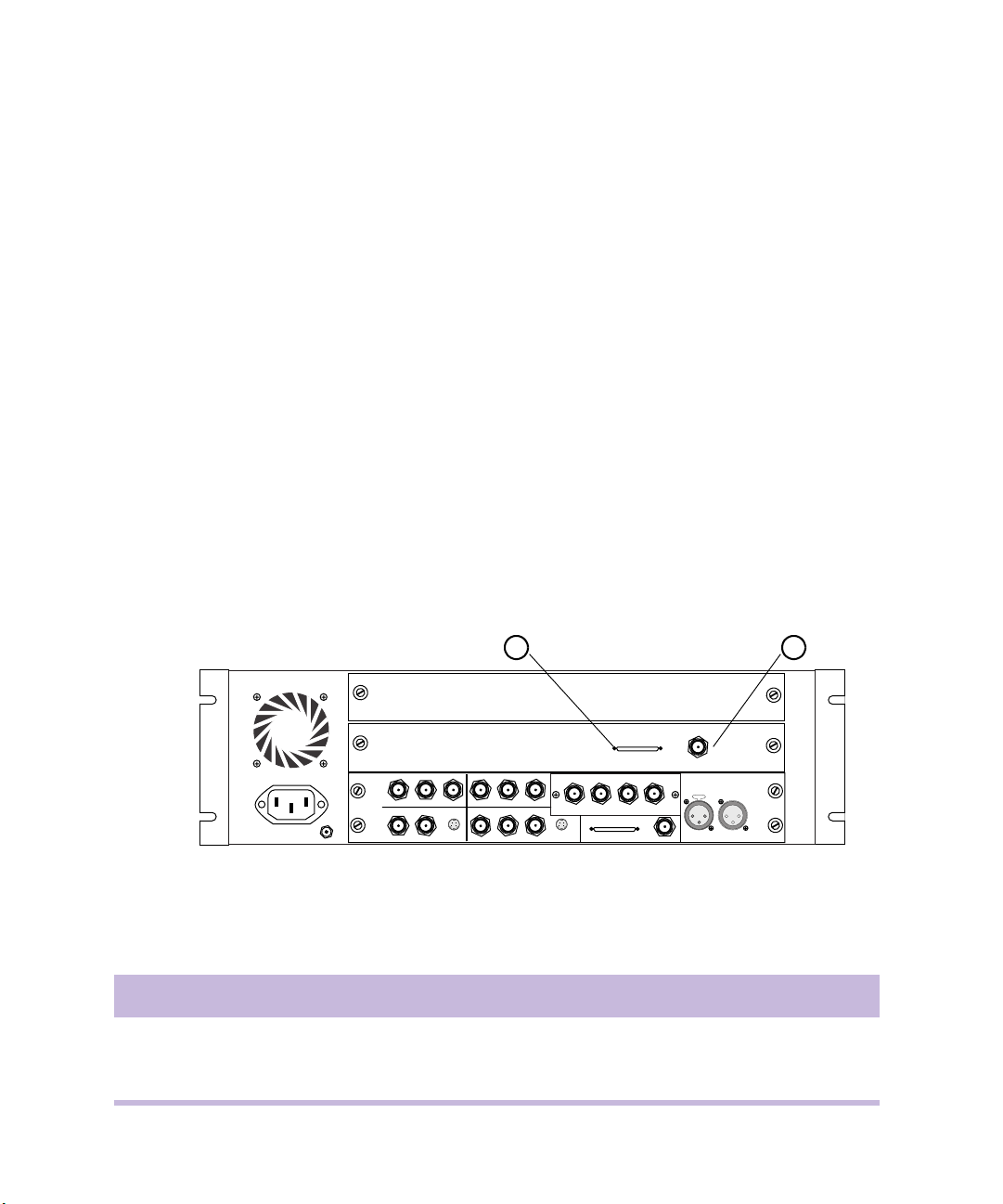
Chapter 4 Connecting Audio and Video Equipment
n
The video board must be in the lower slot of the Meridien I/O box, and the
audio board must be placed in the slot directly above the video board as
shown in Figure 27. Only one audio board can be placed in the Meridien
I/O box at a time.
Meridien I/O Box Connectors
The following sections provide figures and tables that describe the function
of each connector located on the eight-channel and two-channel audio
boards, and the video I/O board. Cabling is shown in later sections of the
chapter.
Eight-Channel Audio Interface Board Connectors
Figure 28 shows the connections on the eight-channel audio interface
board. Table 2 describes the function of each connector.
1 2
COMPONENT
COMPOSITE
8 channel
IN
ININ
Y
R-Y B-Y
IN
S-VIDEO
COMPOSITE
REF
OUT 1
B-Y
Y
R-Y
OUT 3
OUT 2
OUT 1 OUT 2 OUT 3IN
OUT
DIGITAL VIDEO
SYSTEM
OUT
IN / OUT
S-VIDEO
SLAVE CLOCK
OUT
Slave Clock
In
LTC
IN
Figure 28 Eight-Channel Audio Interface Board Connectors
Table 2 Eight-Channel Audio Interface Board Identifiers
Number Label Function
1 8 channel Eight-channel digital interface connection to the audio I/O device
2 Slave Clock In Slave Clock In, for syncing eight-channel audio interface board
68
OUT
Page 69
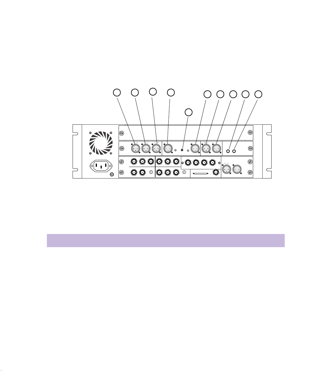
Two-Channel Audio I/O Board Connectors
Figure 29 shows the connections on the two-channel audio I/O board.
Table 3 describes the function of each connector.
Meridien I/O Box Connectors
1 2
3
4
5 6 7 98
10
OUT
SLAVE CLOCK
OUT
S / PDIF
OUT
IN
LTC
OUT
IN
AUDIO IN
IN
COMPONENT
IN
COMPOSITE
MIC CHAN 1
ININ
Y
REF
R-Y B-Y
COMPOSITE
S-VIDEO
CHAN 2
CHAN 2
OUT 1
SERIAL DIGITAL
SYSTEM
IN / OUT
AES / EBU
IN
OUT 3IN
OUT 2
AUDIO OUT
-10
GAIN 2
GAIN 1
+4
CHAN 1
OUT
B-Y
Y
R-Y
OUT
S-VIDEO
OUT 3
OUT 1
OUT 2
Figure 29 Two-Channel Audio I/O Board Connectors
Table 3 Two-Channel Audio I/O Board Identifiers
Number Label Function
1 AUDIO IN MIC Microphone audio input, female connector
2 AUDIO IN CHAN 1 Channel 1 audio input, female connector
3 AUDIO IN CHAN 2 Channel 2 audio input, female connector
4 AUDIO OUT CHAN 1 Channel 1 audio output, male connector
5 AUDIO OUT CHAN 2 Channel 2 audio output, male connector
6 AES/EBU IN AES/EBU digital input, female connector
7 AES/EBU OUT AES/EBU digital output, male connector
69
Page 70
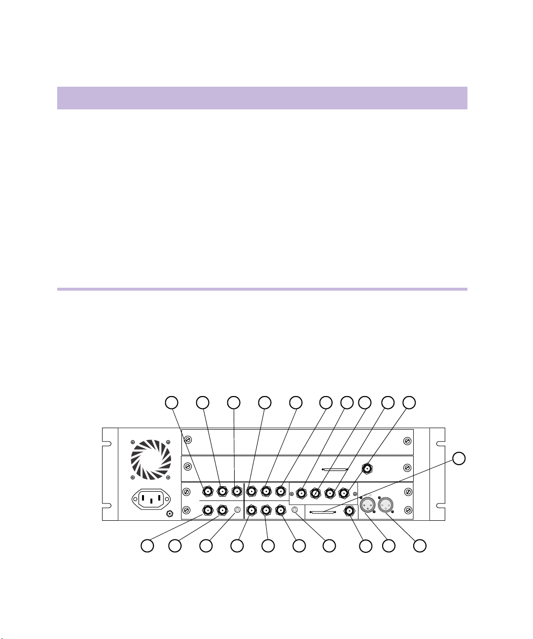
Chapter 4 Connecting Audio and Video Equipment
Table 3 Two-Channel Audio I/O Board Identifiers (Continued)
Number Label Function
8 S/PDIF IN S/PDIF digital input, phono (RCA®) jack
9 S/PDIF OUT S/PDIF digital output, phono (RCA) jack
10 Gain button The button is not a connection, but sets the gain of the
outgoing audio signals:
• +4 dB gain is 0 Vu at +4 dBu signal level.
• -10 dB gain is 0 Vu at -10 dBu signal level.
The Gain button should be IN or OUT (default is OUT)
depending upon the type of deck connected to the board:
• Professional decks — Button should be OUT.
• Consumer decks (for example, a VCR or cassette
recorder) — Button should be IN.
Video I/O Board Connectors
70
Figure 30 shows the connections on the video I/O board. Tab le 4 describes
the function of each connector.
1 2 3 4 5 6
OUT 1 OUT 2 OUT 3IN
OUT
DIGITAL VIDEO
OUT
S-VIDEO
COMPONENT
COMPOSITE
IN
ININ
Y
R-Y B-Y
IN
S-VIDEO
COMPOSITE
REF
OUT 1
B-Y
Y
R-Y
OUT 3
OUT 2
20 19 18 17 16 1521 13 12
Figure 30 Video I/O Board Connectors
7 8 9 10
8 channel
SLAVE CLOCK
SYSTEM
IN / OUT
OUT
Slave Clock
In
IN
14
11
LTC
OUT
Page 71

Meridien I/O Box Connectors
Table 4 Video I/O Board Identifiers
Number Label Function
1 COMPONENT Y IN Video Y component input, BNC connector. Connects to
analog video output of decks.
2 COMPONENT R-Y IN Video R-Y component input, BNC connector. Connects to
analog video output of decks.
3 COMPONENT B-Y IN Video B-Y component input, BNC connector. Connects to
analog video output of decks.
4 COMPONENT Y OUT Video Y component output, BNC connector. Connects to
analog video input of decks.
5 COMPONENT R-Y OUT Video R-Y component output, BNC connector. Connects
to analog video input of decks.
6 COMPONENT B-Y OUT Video B-Y component output, BNC connector. Connects
to analog video input of decks.
7 SDI IN Serial digital input, BNC connector.
8 SDI OUT1 Serial digital output number 1, BNC connector.
9 SDI OUT2 Serial digital output number 2, BNC connector.
10 SDI OUT3 Serial digital output number 3, BNC connector.
11 SYSTEM Audio and video I/O connector from the system
interface board.
12 LTC OUT Longitudinal timecode output, male connector. Master
clock used to stripe tapes and synchronize systems to the
house master clock (SMPTE for NTSC, and EBU for
PA L) .
13 LTC IN Longitudinal timecode input, female connector. Can be
used in place of 9-pin deck control when deck control is
not required.
14 SLAVE CLOCK OUT Clock output, BNC connector. Used to synchronize other
audio or video components.
71
Page 72

Chapter 4 Connecting Audio and Video Equipment
Table 4 Video I/O Board Identifiers (Continued)
Number Label Function
15 S-VIDEO OUT Super-video output, 4-pin connector. Connects to analog
video input of decks.
16 COMPOSITE OUT3 Composite video output, BNC connector. Connects to
analog video input of decks or monitor.
17 COMPOSITE OUT2 Composite video output, BNC connector. Connects to
analog video input of decks or monitor.
18 COMPOSITE OUT1 Composite video output, BNC connector. Connects to
analog video input of decks or monitor.
19 S-VIDEO IN Super-video input, 4-pin connector. Connects to analog
video output of decks.
20 COMPOSITE IN Composite video input, BNC connector. Connects to
analog video output of decks.
21 Video Reference (REF) Black burst or house sync input, BNC connector.
Synchronizes decks that are part of the system.
72
Page 73
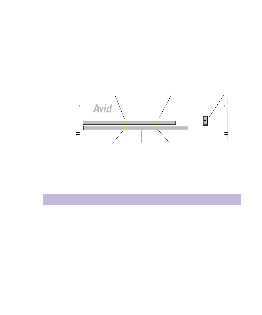
Meridien I/O Box Indicators
P
h
The front panel of the Meridien I/O box has six indicators and a power
switch (see Figure 31). When you turn on the Meridien I/O box, the
indicators turn on and off as it goes through a power-on self-test (POST).
After the POST, the 48-kHz and POWER indicators remain on.
Meridien I/O Box Indicators
44.1 kHz
48 kHz VIDEO SYNC POWER
AUDIO SYNC
44.1 kHz
AUDIO SYNC
48 kHz
VIDEO SYNC
PULL DOWN
PULL DOWN
POWER
O
l
Figure 31 Meridien I/O Box Indicators
Table 5 lists the indicator functions.
Table 5 Meridien I/O Box Indicator Functions
Indicator Function
44.1 kHz The 44.1-kHz indicator is on when 44.1-kHz digital audio is selected in the
Meridien I/O box.
48 kHz The 48-kHz indicator is on when 48-kHz digital audio is selected in the
Meridien I/O box.
ower switc
AUDIO SYNC The audio sync indicator is on when the application is running and the audio sample
clock is within 10 Hz of the expected sample rate.
VIDEO SYNC The video sync indicator is on when video sync or Ref In is detected as a sync in the
Meridien I/O box. If Internal sync is used, the indicator is off.
73
Page 74

Chapter 4 Connecting Audio and Video Equipment
Table 5 Meridien I/O Box Indicator Functions (Continued)
Indicator Function
PULL DOWN The pulldown indicator is on when you play back an NTSC project at 23.976 in the
Timeline, record with the Pulldown button set in the Digitize window (NTSC), or
when performing a digital cut at 23.976 (NTSC).
POWER The power indicator is on when the Meridien I/O box power switch is in the
On (I) position.
Connecting a Client Monitor
The video I/O board provides three composite outputs. You would
normally connect one of these outputs to the Client monitor.
To connect the Client monitor using a composite output:
1. Locate an 8-foot cable labeled “Serial Digital” in the hardware kit. It
has BNC connectors at both ends.
74
n
2. Attach the BNC connector at one end of the cable to COMPOSITE
OUT3 as shown in Figure 32 (you can use COMPOSITE OUT1,
OUT2, or OUT3).
3. Attach the BNC connector at the other end of the cable to the
composite input of the Client monitor.
If you are using a monitor that accepts serial digital input as a Client
monitor, you can also connect a serial digital cable between OUT1, OUT2,
or OUT3 (explained in Table 4 ) on the serial output portion of the video
I/O board to the serial input of the Client monitor.
If you are using a monitor that accepts component signal input as a Client
monitor, you can also connect a component cable (explained in Tab le 4 ) on
the component output portions of the video I/O board to the input of a
component monitor.
Page 75

Synchronizing Audio and Video Equipment
Composite input
CH A
AUDIO
CH B
R/P
CH C
G/Y
SYNC
B/P
VIDEO
INPUT
INPUT
REMOTE
ININ
COMPONENT
R-Y B-Y
YY
COMPOSITE
S-VIDEO
COMPOSITE
REF
OUT 1
POWER
Slave Clock
8 channel
SERIAL DIGITAL
OUT 1 OUT 2 OUT 3IN
OUT
B-Y
R-Y
S-VIDEO
OUT 3
OUT 2
SLAVECLOCK
AVID
OUT
IN / OUT
OUT
Composite Output 3
Figure 32 Connecting the Client Monitor
In
LTC
OUT
IN
Synchronizing Audio and Video Equipment
Avid systems with Meridien hardware require synchronization when
inputting audio and video. Digital audio signals ASE/EBU and
S/PDIF contain their own sync signals and do not need an external sync.
A synchronization signal for analog audio and analog video is generated
internally by the video I/O board from one of the following three sources:
• Internal — The signal generated by the Meridien I/O box internally.
This signal cannot be sent outside the Meridien I/O box.
• Incoming video signal — The sync signal generated by incoming
video: component, composite, S-Video, or serial digital.
• Reference In — The incoming signal (BBGen or house sync) attached
to the panel of the video I/O board at the rear of the Meridien I/O box.
n
By default, the sync signal is generated from incoming video whenever you
digitize video.
75
Page 76

Chapter 4 Connecting Audio and Video Equipment
n
When you are digitizing analog audio only, and a sync is connected to Ref
In, Ref In is automatically selected to sync the incoming audio. If there is
no sync connected to Ref In, the internal sync is used by default to sync the
incoming audio.
Use the following information to help you synchronize the system:
• Eight-channel audio interface boards require synchronization between
the board and the audio I/O device. See “Connecting the Eight-
Channel Audio Board and Audio I/O Device” on page 76.
• Depending on the configuration of the audio and video equipment
attached to the Meridien I/O box, you might need to use a black burst
generator or house sync.
- When you are inputting audio only, you should sync the audio
deck to the Meridien I/O box by connecting a BBGen or house
sync to Ref In on the video I/O board.
- If you are outputting to two decks simultaneously, you should sync
the audio deck to the Meridien I/O box by connecting a BBGen or
house sync to Ref In on the video I/O board, and select Reference
In in the software. See “Connecting the Black Burst Generator
(BBGen)” on page 78 for an example.
Connecting the Eight-Channel Audio Board and Audio I/O Device
Eight-channel audio systems require synchronization to keep the audio and
video signals properly aligned, and a cable to provide eight channels of
digital audio between the eight-channel audio interface board and audio
I/O device.
Basic eight-channel audio connection requires the following components
and cables:
• One eight-channel audio I/O device
• One eight-channel audio interface board
• Two audio sync cables labeled “Slave Clock” (each are 2 feet long)
• One high-density 50-pin cable
76
Page 77

Synchronizing Audio and Video Equipment
To connect an eight-channel audio interface board to the eightchannel audio I/O device:
1. Locate one of two cables labeled “Slave Clock” in the hardware kit.
2. Attach the BNC connector at one end of the cable to Slave Clock In of
the eight-channel audio interface board, labeled A in Figure 33.
3. Attach the other end of the cable to SLAVE CLOCK OUT of the audio
I/O device, labeled B in Figure 33.
4. Locate the second cable labeled “Slave Clock” in the hardware kit.
5. Attach the BNC connector at one end of the cable to SLAVE CLOCK
OUT of the video I/O board, labeled C in Figure 33.
6. Attach the other end of the cable to SLAVE CLOCK IN of the audio
I/O device, labeled D in Figure 33.
n
Audio
I/O device
Eight-channel
audio interface board
Video I/O
board
You must have the eight-channel audio board and eight-channel audio
interface synchronized anytime the eight-channel I/O board is in the
system.
Computer
1234567
1234567
ANALOG OUT ANALOG IN ASE/EBU OUT ASE/EBU IN
8
8
5-6
7-8
1-2
3-4
COMPUTER
1-2
5-6
3-4
7-8
SLAVE CLOCK
S/PDIF
S/PDIF
IN OUT
OUT
IN
System cable
8-channel
Slave Clock
8 channel
ININ
COMPONENT
R-Y B-Y
YY
IN IN
S-VIDEO
COMPOSITE
IN
OUT 1
REF
IN
COMPOSITE
OUT 1 OUT 2 OUT 3IN
OUT
B-Y
R-Y
OUT 2
DIGITAL VIDEO
SYSTEM
OUT
IN / OUT
S-VIDEO
OUT 3
SLAVE CLOCK
In
LTC
OUT
IN
OUT
C
Figure 33 Eight-Channel Synchronization Cabling
D
B
Slave Clock cable
Slave Clock cable
A
77
Page 78

Chapter 4 Connecting Audio and Video Equipment
7. Locate the 50-pin digital system cable.
8. Attach one end of the cable to the connector labeled COMPUTER at
the rear of the audio I/O device.
9. Attach the other end of the cable to the connector labeled
8-channel on the eight-channel audio interface board at the rear of the
Meridien I/O box.
Connecting the Black Burst Generator (BBGen)
The optional black burst generator supplies a common reference signal to
many of the components in the system.
To connect the black burst generator to a power source:
1. Attach the ac power module and cord to the power connector on the
back of the black burst generator (see Figure 34).
2. Plug the ac power module into a power strip.
78
BB3
BB2
BB1
Power connector
Figure 34 Black Burst Generator Power Cabling
AC power module
Page 79

Synchronizing Audio and Video Equipment
Connecting the BBGen to Two Video Decks
You might have to sync two decks to the Meridien I/O box when
configuring your video equipment as shown in Figure 35.
To sync two decks to the Meridien I/O box using a BBGen:
1. Locate three sync cables with BNC connectors at both ends (these are
not provided in the hardware kit).
2. Attach the BNC connector of cable A to BB3 output of the BBGen.
(BB3 is used as an example; any output can be used.)
3. Attach the BNC connector at the other end of cable A to Ref In on the
video board.
4. Attach the BNC connector of cable B to BB1 output of the BBGen.
(BB1 is used as an example; any output can be used.)
5. Attach the BNC connector at the other end of cable B to Ref In on the
first deck.
6. Switch the terminator for the Ref In to the OFF position on the first
deck.
n
c
If you need to sync only one deck to the system, make sure you have the
deck’s Ref In terminator switch in the ON position.
7. Attach the BNC connector of cable C to passthrough Ref In on the first
deck.
8. Attach the BNC connector at the other end of cable C to Ref In on the
second deck.
9. Switch the terminator for the Ref In to the ON position on the second
deck.
Avid suggests you use a common sync (BBGen or house sync)
whenever you output simultaneously to two different decks, or you are
inputting “audio only” from one deck. Figure 35 shows an example of
how to connect the sync cables between the BBGen and two decks.
79
Page 80
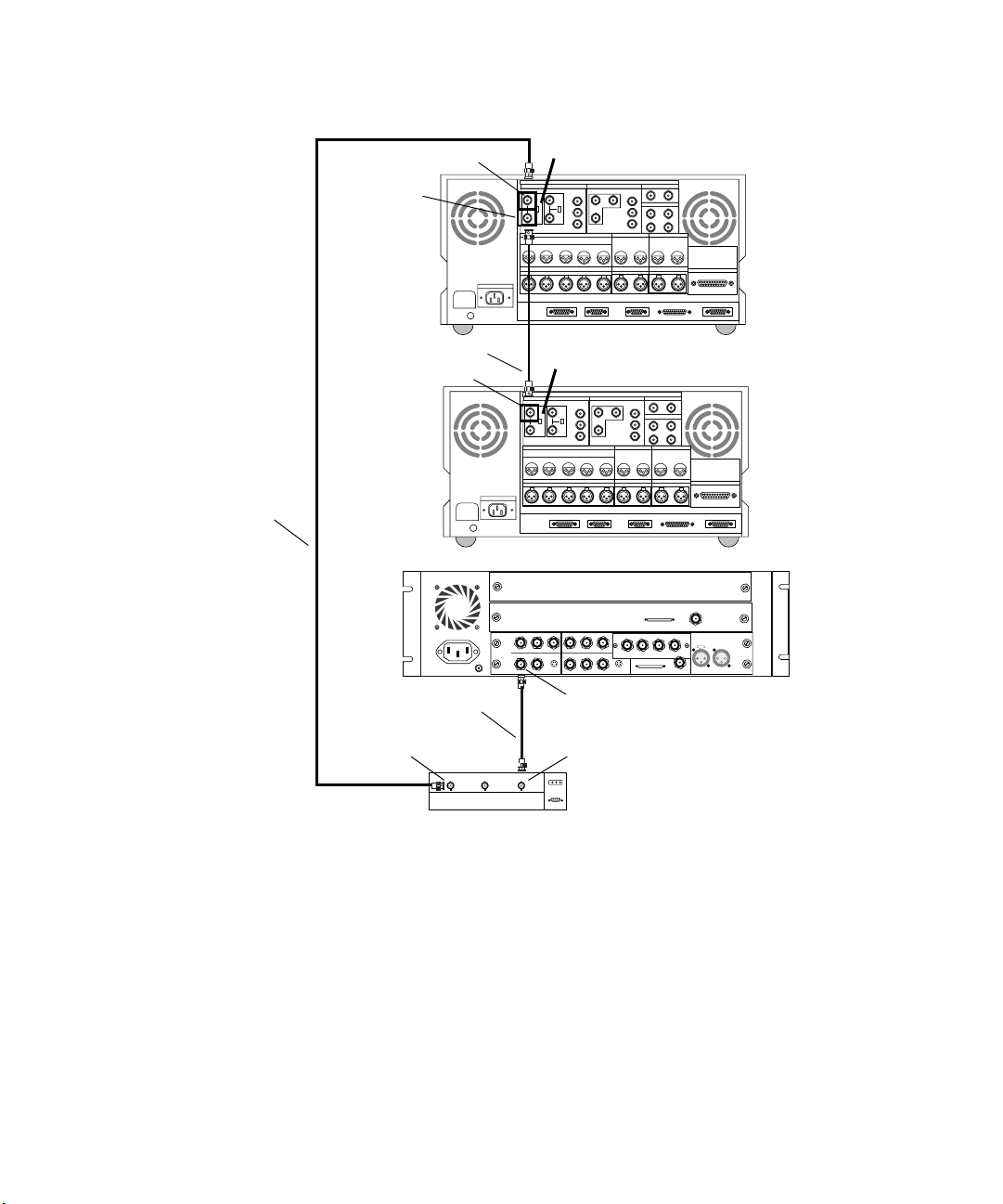
Chapter 4 Connecting Audio and Video Equipment
Cable B
Passthrough
Ref In
Ref In
BREAKER
Cable C
Ref In
BREAKER
Cable A
Terminator OFF
VIDEO INPUT
REF COMPONENTCOMPOSITE COMPONENTCOMPOSITE
75ON75
ON
OFF OFF
AUDIO INPUT
CH1 CH2 CH3 CH4 CH1/2 CH3/4
CH1 CH2 CH3 CH4
AC IN
CUE
AUDIO OUTPUT AUDIO OUTPUT
CUE
REMOTE1 IN REMOTE1 OUT RS232C VIDEO CONTROL
CONTROL PANEL
Terminator ON
VIDEO INPUT
REF COMPONENTCOMPOSITE COMPONENTCOMPOSITE
75ON75
ON
OFF OFF
AUDIO INPUT
CH1 CH2 CH3 CH4 CH1/2 CH3/4
CH1 CH2 CH3 CH4
AC IN
IN
ININ
COMPONENT
R-Y B-Y
YY
IN
COMPOSITE
COMPOSITE
REF
CUE
AUDIO OUTPUT AUDIO OUTPUT
CUE
REMOTE1 IN REMOTE1 OUT RS232C VIDEO CONTROL
CONTROL PANEL
B-Y
R-Y
S-VIDEO
OUT 1
OUT 3
OUT 2
Ref In
VIDEO OUTPUT
IN
MONITOR OUTPUT
RL
VIDEO OUTPUT
RL
OUT
S-VIDEO
TIME CODE
TIME CODE
IN
MONITOR OUTPUT
OUT
DIGITAL I/OANALOG I/O
SERIAL V/A INPUT
SERIAL V/A OUTPUT
AUDIO INPUT
OUT
DIGITAL I/OANALOG I/O
AUDIO INPUT
CH1/2 CH3/4
AUDIO CLOCK
OUT
Slave Clock
REMOTE
PARALLEL I/O
PARALLEL I/O
In
LTC
IN
CH1/2 CH3/4
SERIAL V/A INPUT
SERIAL V/A OUTPUT
OUT
8 channel
OUT 1 OUT 2 OUT 3IN
DIGITAL VIDEO
SYSTEM
IN / OUT
REMOTE
OUT
First deck
Second deck
80
n
BB1
BB3
BB3BB1 BB2
Figure 35 Connecting the Black Burst Generator
You can also sync the two decks to the Meridien I/O box by attaching a
cable between BB2 and Ref In of the second deck instead of using the
passthrough Ref In from the first deck. If you do this, you must terminate
Ref In on both decks.
Page 81

Controlling a Video Deck
Avid systems can provide video deck control through the serial control
connector on most decks. You can connect a single deck to your system
using the USB-to-serial adapter and a direct serial cable with a round 8-pin
DIN connector at one end and a 9-pin D connector at the other end.
To connect a single deck to your system:
1. Locate a serial cable.
2. Attach the round 8-pin DIN connector to a serial port connector on the
USB-to-serial adapter (see Figure 36).
3. Attach the 9-pin D connector to the serial connector on the back of the
deck.
Controlling a Video Deck
8-pin DIN connector
to a port on the USB-to-serial adapter
n
n
Figure 36 Connecting to the Serial Adapter
The USB-to-serial adapter requires its own software. See “Connecting
USB Devices” on page 46 for more information.
You might have to place the video deck in Remote mode by turning a switch
before attempting to control the video deck using the software.
81
Page 82
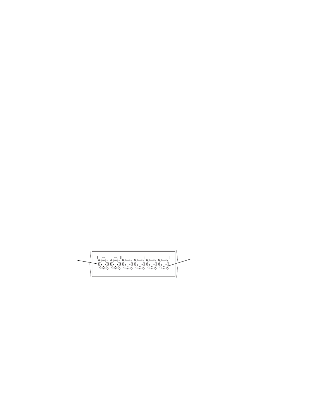
Chapter 4 Connecting Audio and Video Equipment
Connecting Audio Equipment
Audio equipment is not directly connected to the system. Depending upon
the system you purchase, audio equipment connects to one of the
following:
• An eight-channel audio I/O device. The audio device is then connected
to the eight-channel audio interface board of the Meridien I/O box.
• A two-channel audio splitter that connects to an audio I/O board in the
Meridien I/O box.
n
You might need to synchronize the audio equipment to the Meridien I/O
box. See “Synchronizing Audio and Video Equipment” on page 75 for
details.
To connect up to eight channels of audio to the system, you use the eightchannel audio interface board and the eight-channel audio I/O device.
Connecting the Audio Splitter
Avid ships an audio splitter (see Figure 37) that allows you to input two
channels of audio and send both channels to two speakers and a video
deck.
Female
connection
Line In Line Out Monitor Out
Left Right Left RightLeft Right
Figure 37 Audio Splitter Rear View
The splitter is placed between:
Male
connection
82
• Two audio output channels of either the 888 I/O audio device or the
two-channel audio I/O board and two speakers.
• Two audio outputs of either the 888 I/O audio device or the
two-channel audio I/O board and two channels of a record deck.
Page 83
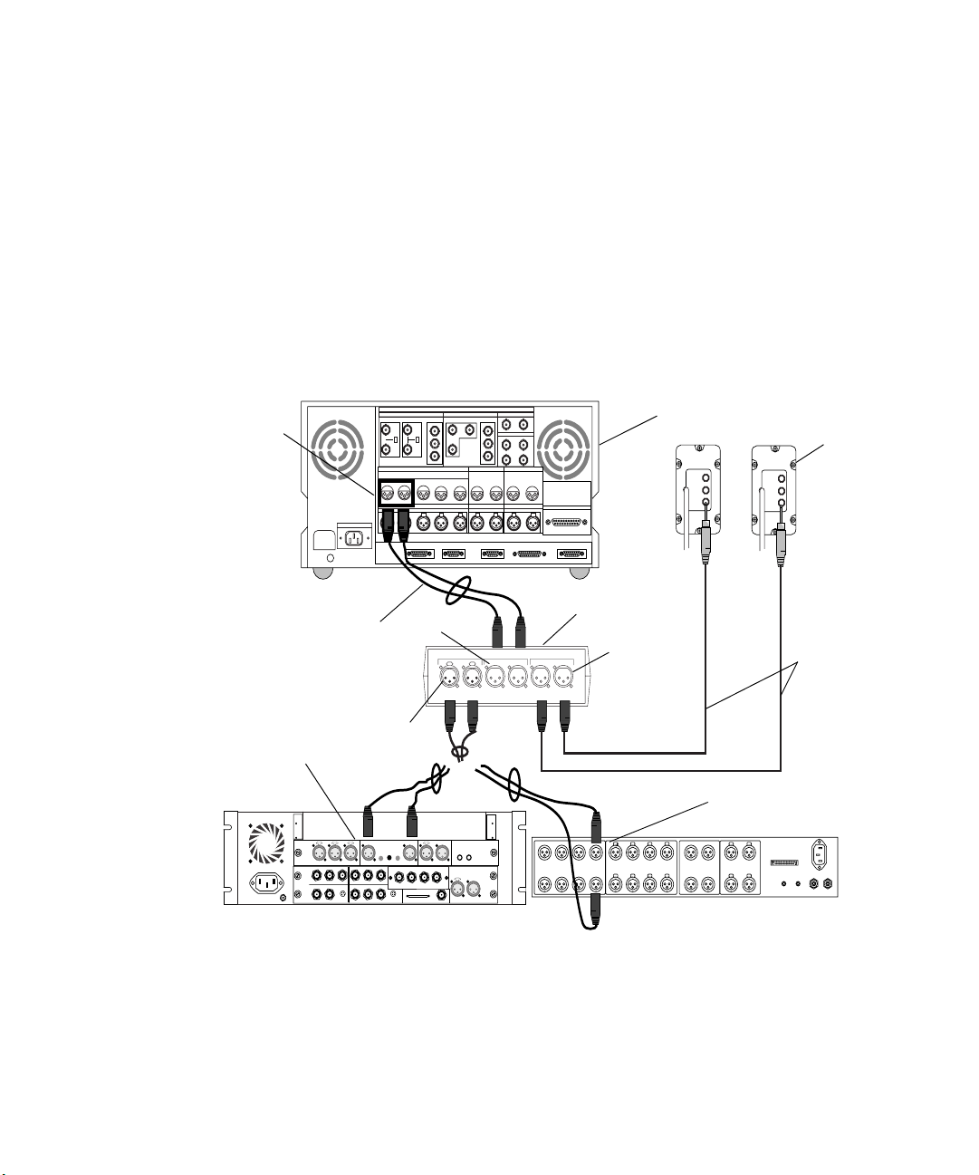
Connecting Audio Equipment
To connect the audio splitter using channels 1 and 2 as an example:
1. Locate one of the two-channel XLR to XLR cables shipped with the
system. (This is two XLR to XLR cables bound together to form one
cable.)
- Connect the two female connectors of the cable to the analog
output of channels 1 and 2 of either the 888 I/O audio device or the
two-channel audio I/O board (see Figure 38).
- Connect the two male connectors of the cable to the Left and Right
connections of Line In on the audio splitter.
AUDIO INPUT
Audio
output to deck
Two-channel audio
I/O board
BREAKER
VIDEO INPUT
REF COMPONENTCOMPOSITE COMPONENTCOMPOSITE
75ON75
ON
OFF OFF
CH1 CH2 CH3 CH4 CH1/2 CH3/4
CH1 CH2 CH3 CH4
AC IN
VIDEO OUTPUT
AUDIO INPUT
CUE
AUDIO OUTPUT AUDIO OUTPUT
CUE
REMOTE1 IN REMOTE1 OUT RS232C VIDEO CONTROL
CONTROL PANEL
SERIAL V/A INPUT
SERIAL V/A OUTPUT
TIME CODE
OUT
IN
MONITOR OUTPUT
RL
DIGITAL I/OANALOG I/O
AUDIO INPUT
CH1/2 CH3/4
REMOTE
PARALLEL I/O
Record deck
MIC.
INST.
LINE
Speakers
MIC.
INST.
LINE
Audio splitter
Line Out
Line In Line Out Monitor Out
Left Right Left RightLeft Right
Monitor Out
XLR to ¼-inch
Line In
888 I/O audio device
AES / EBU
AUDIO IN
MIC CHAN 1
IN
ININ
Y
COMPONENT
R-Y B-Y
IN
COMPOSITE
COMPOSITE
REF
AUDIO OUT
-10
GAIN 1
GAIN 2
CHAN 2
+4
CHAN 1
OUT
B-Y
Y
R-Y
S-VIDEO
OUT
S-VIDEO
OUT 1
OUT 3
OUT 2
S / PDIF
IN
OUT
IN
CHAN 2
OUT 1 OUT 2 OUT 3IN
DIGITAL VIDEO
OUT
LTC
SLAVE CLOCK
SYSTEM
IN
IN / OUT
OUT
OUT
1234567
ANALOG OUT ANALOG IN ASE/EBU OUT ASE/EBU IN
8
1234567
1-2
8
5-6
3-4
7-8
COMPUTER
1-2
5-6
3-4
7-8
SLAVE CLOCK
S/PDIF
S/PDIF
IN OUT
OUT
IN
Figure 38 Connecting the Audio Splitter
83
Page 84

Chapter 4 Connecting Audio and Video Equipment
2. Locate the two XLR to ¼-inch cables shipped with the system.
- Connect the female XLR connectors to the Left and Right
connections of Monitor Out on the audio splitter.
- Connect the ¼-inch connectors to the left and right speakers as
shown in Figure 38.
3. Locate the remaining two-channel XLR to XLR cable shipped with the
system. (This is two XLR to XLR cables bound together to form one
cable.)
- Connect the two female connectors of the cable to the Left and
Right connections of Line Out on the audio splitter (see
Figure 38).
- Connect the two male connectors of the cable to channels 1 and 2
of AUDIO INPUT on the record deck.
Connecting the Video Input/Output Board to Decks
Because there are many possible cabling configurations for different
combinations of video decks and Client monitors, only basic installations
are presented in this guide.
Connecting a Single Video Deck — Component Signal
A single component video deck connection to the video I/O board requires
the following components and cables:
• Two cables labeled “Component Video”
• A video deck capable of component I/O
To connect the I/O of a single deck using component signals on the
video board:
1. Locate one cable labeled “Component Video.”
There are three BNC connectors on each end of the cable. Each BNC
is attached to a different colored wire (red, green, and blue).
84
Page 85
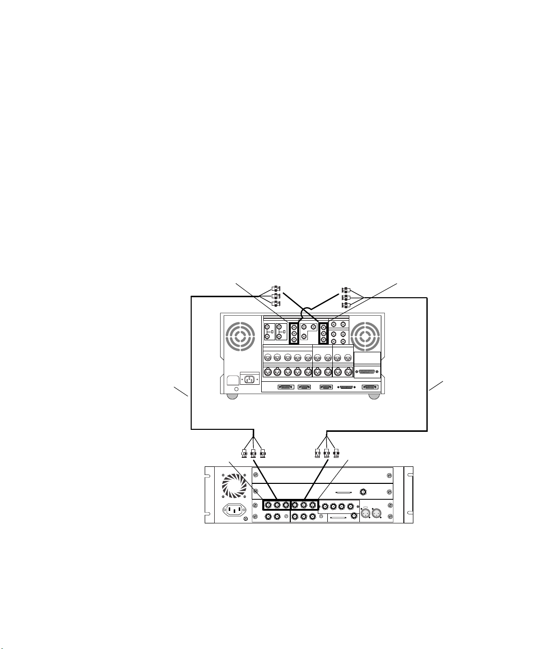
Connecting the Video Input/Output Board to Decks
2. Attach one end of the cable labeled A in Figure 39 (using the three
BNC connectors) to COMPONENT OUT on the video I/O board as
follows:
The BNC attached to the green wire to the connector labeled Y.
The BNC attached to the red wire to the connector labeled R-Y.
The BNC attached to the blue wire to the connector labeled B-Y.
3. Attach the other end of Cable A (using the three BNC connectors) to
COMPONENT IN of the deck as follows:
The BNC attached to the green wire to the connector labeled Y.
The BNC attached to the red wire to the connector labeled R-Y.
The BNC attached to the blue wire to the connector labeled B-Y.
Cable B
COMPONENT IN
COMPONENT IN
DIGITAL I/OANALOG I/O
VIDEO INPUT
REF COMPONENTCOMPOSITE COMPONENTCOMPOSITE
75ON75
ON
OFF OFF
AUDIO INPUT
CH1 CH2 CH3 CH4 CH1/2 CH3/4
AUDIO OUTPUT AUDIO OUTPUT
CH1 CH2 CH3 CH4
AC IN
BREAKER
REMOTE1 IN REMOTE1 OUT RS232C VIDEO CONTROL
CONTROL PANEL
VIDEO OUTPUT
CUE
CUE
TIME CODE
OUT
IN
MONITOR OUTPUT
RL
SERIAL V/A INPUT
SERIAL V/A OUTPUT
AUDIO INPUT
CH1/2 CH3/4
REMOTE
PARALLEL I/O
COMPONENT OUT
Cable A
COMPONENT OUT
Slave Clock
8 channel
IN
ININ
COMPONENT
R-Y B-Y
YY
IN
COMPOSITE
S-VIDEO
COMPOSITE
REF
OUT 1 OUT 2 OUT 3IN
OUT
B-Y
R-Y
OUT
S-VIDEO
OUT 1
OUT 3
OUT 2
DIGITAL VIDEO
SYSTEM
IN / OUT
AUDIO CLOCK
In
LTC
OUT
IN
OUT
Figure 39 Connecting a Video Deck — Component Signal
85
Page 86

Chapter 4 Connecting Audio and Video Equipment
4. Locate a second cable labeled “Component Video.”
There are three BNC connectors on each end of the cable. Each BNC
is attached to a different colored wire (red, green, and blue).
5. Attach one end of the cable labeled B in Figure 39 (using the three
BNC connectors) to COMPONENT IN on the video I/O board as
follows:
The BNC attached to the green wire to the connector labeled Y.
The BNC attached to the red wire to the connector labeled R-Y.
The BNC attached to the blue wire to the connector labeled B-Y.
6. Attach the other end of Cable B (using the three BNC connectors) to
COMPONENT OUT of the deck as follows:
The BNC attached to the green wire to the connector labeled Y.
The BNC attached to the red wire to the connector labeled R-Y.
The BNC attached to the blue wire to the connector labeled B-Y.
n
Make sure you terminate the input signal if your video deck supports
passthrough.
Connecting Two Video Decks — Component Signal
You might want to input (digitize) video from one deck and output video
(lay-back) to a second deck. Connecting two component video decks to a
video I/O board, one as input and one as output, requires the following
components and cables:
• Two cables labeled “Component Video”
• Two video decks capable of component I/O
To connect two decks, one as input and one as output, using a
component signal:
1. Locate one cable labeled “Component Video.”
There are three BNC connectors on each end of the cable. Each BNC
is attached to a different colored wire (red, green, and blue).
86
Page 87

Connecting the Video Input/Output Board to Decks
2. Attach one end of the cable labeled A in Figure 40 (using the three
BNC connectors) to COMPONENT IN on the video I/O board as
follows:
The BNC attached to the green wire to the connector labeled Y.
The BNC attached to the red wire to the connector labeled R-Y.
The BNC attached to the blue wire to the connector labeled B-Y.
3. Attach the other end of Cable A (using the three BNC connectors) to
COMPONENT OUT of the second video deck as follows:
The BNC attached to the green wire to the connector labeled Y.
The BNC attached to the red wire to the connector labeled R-Y.
The BNC attached to the blue wire to the connector labeled B-Y.
4. Locate a second cable labeled “Component Video.”
There are three BNC connectors on each end of the cable. Each BNC
is attached to a different colored wire (red, green, and blue).
5. Attach one end of the cable labeled B in Figure 40 (using the three
BNC connectors) to COMPONENT OUT on the video I/O board as
follows:
n
The BNC attached to the green wire to the connector labeled Y.
The BNC attached to the red wire to the connector labeled R-Y.
The BNC attached to the blue wire to the connector labeled B-Y.
6. Attach the other end of Cable B (using the three BNC connectors) to
COMPONENT IN of the first video deck as follows:
The BNC attached to the green wire to the connector labeled Y.
The BNC attached to the red wire to the connector labeled R-Y.
The BNC attached to the blue wire to the connector labeled B-Y.
Make sure you terminate the input signal if your video deck supports
passthrough.
87
Page 88
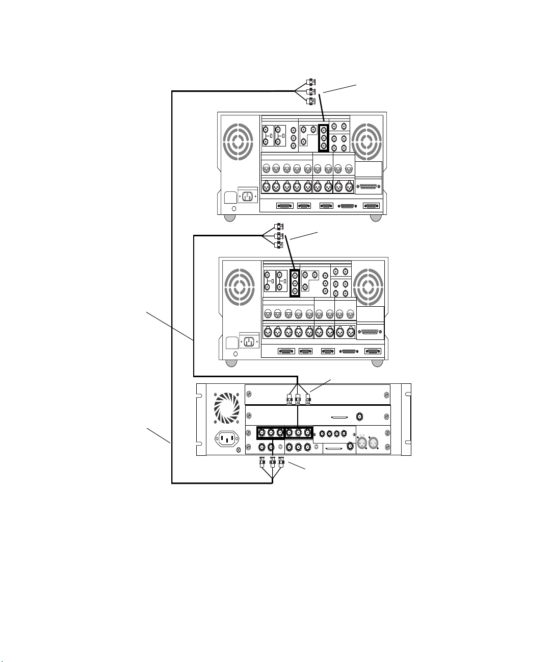
Chapter 4 Connecting Audio and Video Equipment
AC IN
BREAKER
Cable B
AC IN
BREAKER
DIGITAL I/OANALOG I/O
VIDEO INPUT
REF COMPONENTCOMPOSITE COMPONENTCOMPOSITE
75ON75
ON
OFF OFF
AUDIO INPUT
CH1 CH2 CH3 CH4 CH1/2 CH3/4
AUDIO OUTPUT AUDIO OUTPUT
CH1 CH2 CH3 CH4
REMOTE1 IN REMOTE1 OUT RS232C VIDEO CONTROL
CONTROL PANEL
VIDEO OUTPUT
CUE
IN
MONITOR OUTPUT
RL
CUE
TIME CODE
OUT
SERIAL V/A INPUT
SERIAL V/A OUTPUT
AUDIO INPUT
CH1/2 CH3/4
COMPONENT IN
DIGITAL I/OANALOG I/O
VIDEO INPUT
REF COMPONENTCOMPOSITE COMPONENTCOMPOSITE
75ON75
ON
OFF OFF
AUDIO INPUT
CH1 CH2 CH3 CH4 CH1/2 CH3/4
AUDIO OUTPUT AUDIO OUTPUT
CH1 CH2 CH3 CH4
REMOTE1 IN REMOTE1 OUT RS232C VIDEO CONTROL
CONTROL PANEL
VIDEO OUTPUT
CUE
IN
MONITOR OUTPUT
RL
CUE
TIME CODE
OUT
SERIAL V/A INPUT
SERIAL V/A OUTPUT
AUDIO INPUT
CH1/2 CH3/4
COMPONENT OUT
Second deck
REMOTE
PARALLEL I/O
First deck
REMOTE
PARALLEL I/O
88
Cable A
COMPONENT OUT
AUDIO IN
MIC CHAN 1
CHAN 2
IN
ININ
COMPONENT
R-Y B-Y
YY
IN
COMPOSITE
S-VIDEO
COMPOSITE
OUT 1
REF
AUDIO OUT
GAIN 1
CHAN 1
B-Y
R-Y
OUT 3
OUT 2
AES / EBU
-10
GAIN 2
CHAN 2
+4
OUT 1 OUT 2 OUT 3IN
OUT
DIGITAL VIDEO
SYSTEM
OUT
IN / OUT
S-VIDEO
8 channel
IN
SLAVECLOCK
OUT
OUT
Slave Clock
In
IN
S / PDIF
IN
OUT
LTC
OUT
COMPONENT IN
Figure 40 Connecting Two Video Decks — Component Signal
Page 89

Connecting the Video Input/Output Board to Decks
Connecting a Single Video Deck — Composite Signal
A single composite video deck connection to the video I/O board requires
the following components and cables:
• Two cables labeled “Composite Video” (you can also use the “Serial
Digital” cables)
• A video deck capable of composite I/O
To connect a deck as input and output using a composite signal:
1. Locate one cable labeled “Composite Video” (labeled Cable A in
Figure 41).
2. Attach the BNC connector at one end of Cable A to COMPOSITE
OUT1 on the video I/O board (although not recommended, you could
also use COMPOSITE OUT2 or COMPOSITE OUT3).
3. Attach the BNC connector at the other end of Cable A to
COMPOSITE IN on the video deck.
n
Make sure you terminate the input signal if your video deck supports
passthrough.
4. Locate a second cable labeled “Composite Video” (labeled Cable B in
Figure 41).
5. Attach the BNC connector at one end of Cable B to COMPOSITE IN
on the video I/O board.
6. Attach the BNC connector at the other end of Cable B to
COMPOSITE OUT on the video deck.
89
Page 90

Chapter 4 Connecting Audio and Video Equipment
Cable B
Cable A
COMPOSITE IN
BREAKER
COMPOSITE IN
Terminator
VIDEO INPUT
REF COMPONENTCOMPOSITE COMPONENTCOMPOSITE
75ON75
ON
OFF OFF
AUDIO INPUT
CH1 CH2 CH3 CH4 CH1/2 CH3/4
CH1 CH2 CH3 CH4
AC IN
AUDIO IN
MIC CHAN 1
IN
ININ
COMPONENT
YY
IN
COMPOSITE
COMPOSITE
REF
CUE
AUDIO OUTPUT AUDIO OUTPUT
CUE
REMOTE1 IN REMOTE1 OUT RS232C VIDEO CONTROL
CONTROL PANEL
CHAN 2
CHAN 1
R-Y B-Y
R-Y
S-VIDEO
OUT 1
OUT 2
COMPOSITE OUT
DIGITAL I/OANALOG I/O
SERIAL V/A INPUT
VIDEO OUTPUT
SERIAL V/A OUTPUT
TIME CODE
AUDIO INPUT
OUT
IN
MONITOR OUTPUT
CH1/2 CH3/4
RL
AUDIO OUT
GAIN 1
OUT
B-Y
OUT 3
AES / EBU
-10
GAIN 2
IN
CHAN 2
+4
S-VIDEO
OUT 3IN
OUT 1 OUT 2
SLAVE CLOCK
DIGITAL VIDEO
SYSTEM
OUT
IN / OUT
COMPOSITE OUT1
REMOTE
PARALLEL I/O
S / PDIF
IN
OUT
OUT
LTC
OUT
IN
OUT
90
Figure 41 Connecting a Video Deck — Composite Signal
Page 91

Connecting the Video Input/Output Board to Decks
Connecting Two Video Decks — Composite Signal
You might want to input (digitize) video from one deck and output video
(lay-back) to a second deck. Connecting two composite video decks to a
video I/O board, one as input and one as output, requires the following
components and cables:
• Two cables labeled “Composite Video”
• Two video decks capable of composite I/O
To connect two decks, one as input and one as output, using a
composite signal:
1. Locate one cable labeled “Composite Video” (labeled Cable A in
Figure 42).
2. Attach the BNC connector at one end of Cable A to COMPOSITE IN
on the video I/O board.
3. Attach the BNC connector at the other end of Cable A to
COMPOSITE OUT on the first video deck.
n
n
4. Locate a second cable labeled “Composite Video” (labeled Cable B in
Figure 42).
5. Attach the BNC connector at one end of Cable B to COMPOSITE
OUT3 on the video I/O board (you could also use COMPOSITE
OUT1 or COMPOSITE OUT2).
6. Attach the BNC connector at the other end of Cable B to
COMPOSITE IN on the second video deck.
Avid recommends you use an external sync for outputting to two decks
simultaneously (see “Synchronizing Audio and Video Equipment” on
page 75).
Make sure you terminate the input signal if your video deck supports
passthrough.
91
Page 92

Chapter 4 Connecting Audio and Video Equipment
Cable A
COMPOSITE IN
Second deck
First deck
COMPOSITE IN
Terminator
DIGITAL I/OANALOG I/O
VIDEO INPUT
REF COMPONENTCOMPOSITE COMPONENTCOMPOSITE
75ON75
ON
OFF OFF
AUDIO INPUT
CH1 CH2 CH3 CH4 CH1/2 CH3/4
AUDIO OUTPUT AUDIO OUTPUT
CH1 CH2 CH3 CH4
AC IN
BREAKER
REMOTE1 IN REMOTE1 OUT RS232C VIDEO CONTROL
CONTROL PANEL
VIDEO OUTPUT
CUE
CUE
TIME CODE
OUT
IN
MONITOR OUTPUT
RL
SERIAL V/A INPUT
SERIAL V/A OUTPUT
AUDIO INPUT
CH1/2 CH3/4
PARALLEL I/O
REMOTE
COMPOSITE OUT
Cable B
DIGITAL I/OANALOG I/O
VIDEO INPUT
REF COMPONENTCOMPOSITE COMPONENTCOMPOSITE
75ON75
ON
OFF OFF
AUDIO INPUT
CH1 CH2 CH3 CH4 CH1/2 CH3/4
AUDIO OUTPUT AUDIO OUTPUT
CH1 CH2 CH3 CH4
AC IN
BREAKER
IN
ININ
COMPONENT
YY
IN
COMPOSITE
COMPOSITE
REF
REMOTE1 IN REMOTE1 OUT RS232C VIDEO CONTROL
CONTROL PANEL
R-Y B-Y
R-Y
S-VIDEO
OUT 1
OUT 2
VIDEO OUTPUT
CUE
CUE
B-Y
OUT 3
TIME CODE
OUT
IN
MONITOR OUTPUT
RL
OUT
OUT
S-VIDEO
SERIAL V/A INPUT
SERIAL V/A OUTPUT
OUT 1 OUT 2 OUT 3IN
DIGITAL VIDEO
SYSTEM
IN / OUT
AUDIO INPUT
CH1/2 CH3/4
8 channel
AUDIO CLOCK
OUT
Slave Clock
REMOTE
PARALLEL I/O
In
LTC
OUT
IN
COMPOSITE OUT3
92
Figure 42 Connecting Two Video Decks — Composite Signal
Page 93

Connecting the Video Input/Output Board to Decks
Connecting a Single Video Deck — Digital Signal
A single digital video deck connection to the video I/O board requires the
following components and cables:
• Two cables labeled “Serial Digital”
• A video deck capable of serial digital I/O
To connect a deck as input and output using a serial digital signal:
1. Locate one cable labeled “Serial Digital” (labeled Cable A in
Figure 43).
2. Attach the BNC connector at one end of Cable A to IN on the Serial
Digital portion of the video I/O board.
3. Attach the BNC connector at the other end of Cable A to SERIAL
OUTPUT on the video deck.
n
Make sure you terminate the input signal if your video deck supports
passthrough.
4. Locate a second cable labeled “Serial Digital” (labeled Cable B in
Figure 43).
5. Attach the BNC connector at one end of Cable B to OUT1 on the
Serial Digital portion of the video I/O board.
6. Attach the BNC connector at the other end of Cable B to SERIAL
INPUT on the video deck.
93
Page 94

Chapter 4 Connecting Audio and Video Equipment
SERIAL
OUTPUT
VIDEO INPUT
REF COMPONENTCOMPOSITE COMPONENTCOMPOSITE
75ON75
ON
OFF OFF
AUDIO INPUT
CH1 CH2 CH3 CH4 CH1/2 CH3/4
AUDIO OUTPUT AUDIO OUTPUT
CH1 CH2 CH3 CH4
AC IN
Cable A Cable B
BREAKER
ININ
Y
COMPONENT
COMPOSITE
REF
COMPOSITE
REMOTE1 IN REMOTE1 OUT RS232C VIDEO CONTROL
CONTROL PANEL
R-Y B-Y
Y
R-Y
S-VIDEO
OUT 1
OUT 2
VIDEO OUTPUT
CUE
CUE
B-Y
OUT 3
TIME CODE
IN
MONITOR OUTPUT
RL
OUT
OUT
S-VIDEO
OUT
OUT 1 OUT 2 OUT 3IN
SERIAL DIGITAL
IN / OUT
SERIAL V/A INPUT
SERIAL V/A OUTPUT
CH1/2 CH3/4
8 channel
SYSTEM
IN
SERIAL
INPUT
DIGITAL I/OANALOG I/O
AUDIO INPUT
REMOTE
PARALLEL I/O
Slave Clock
In
LTC
SLAVE CLOCK
OUT
IN
OUT
OUT1
Figure 43 Connecting a Video Deck — Digital Signal
94
Page 95

Connecting the Video Input/Output Board to Decks
Connecting Two Video Decks — Digital Signal
You might want to input (digitize) video from one deck and output video
(lay-back) to a second deck. Connecting two serial digital video decks to a
video I/O board, one as input and one as output, requires the following
components and cables:
• Two cables labeled “Serial Digital”
• Two video decks capable of serial digital I/O
To connect two decks, one as input and one as output, using a serial
digital signal:
1. Locate one cable labeled “Serial Digital” (labeled Cable A in
Figure 44).
2. Attach the BNC connector at one end of Cable A to IN on the Serial
Digital portion of the video I/O board.
3. Attach the BNC connector at the other end of Cable A to SERIAL
OUTPUT on the first video deck.
n
n
Make sure you terminate the input signal if your video deck supports
passthrough.
4. Locate a second cable labeled “Serial Digital” (labeled Cable B in
Figure 44).
5. Attach the BNC connector at one end of Cable B to OUT1 on the
Serial Digital portion of the video I/O board.
6. Attach the BNC connector at the other end of Cable B to SERIAL
INPUT on the second video deck.
Avid recommends you use an external sync for outputting to two decks
simultaneously (see “Synchronizing Audio and Video Equipment” on
page 75).
95
Page 96
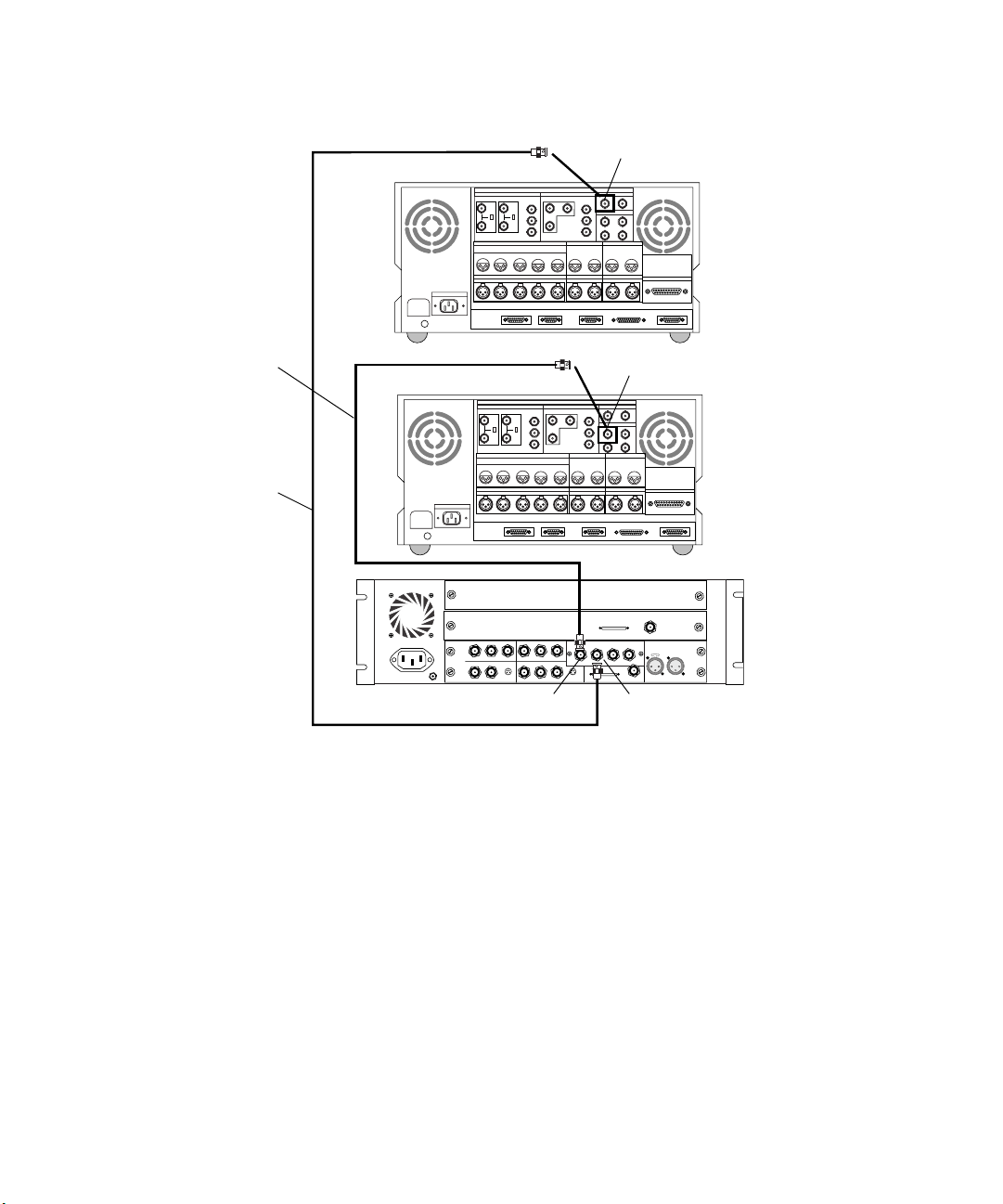
Chapter 4 Connecting Audio and Video Equipment
AC IN
BREAKER
DIGITAL I/OANALOG I/O
VIDEO INPUT
REF COMPONENTCOMPOSITE COMPONENTCOMPOSITE
75ON75
ON
OFF OFF
AUDIO INPUT
CH1 CH2 CH3 CH4 CH1/2 CH3/4
AUDIO OUTPUT AUDIO OUTPUT
CH1 CH2 CH3 CH4
REMOTE1 IN REMOTE1 OUT RS232C VIDEO CONTROL
CONTROL PANEL
VIDEO OUTPUT
CUE
CUE
TIME CODE
OUT
IN
MONITOR OUTPUT
RL
SERIAL V/A INPUT
SERIAL V/A OUTPUT
AUDIO INPUT
CH1/2 CH3/4
SERIAL INPUT
REMOTE
PARALLEL I/O
Second deck
Cable A
Cable B
SERIAL OUTPUT
DIGITAL I/OANALOG I/O
VIDEO INPUT
REF COMPONENTCOMPOSITE COMPONENTCOMPOSITE
75ON75
ON
OFF OFF
AUDIO INPUT
CH1 CH2 CH3 CH4 CH1/2 CH3/4
AUDIO OUTPUT AUDIO OUTPUT
CH1 CH2 CH3 CH4
AC IN
BREAKER
IN
ININ
COMPONENT
YY
IN
COMPOSITE
COMPOSITE
REF
REMOTE1 IN REMOTE1 OUT RS232C VIDEO CONTROL
CONTROL PANEL
R-Y B-Y
R-Y
S-VIDEO
OUT 1
OUT 2
IN
VIDEO OUTPUT
CUE
CUE
B-Y
OUT 3
TIME CODE
IN
MONITOR OUTPUT
RL
IN
OUT
OUT
S-VIDEO
SERIAL V/A INPUT
SERIAL V/A OUTPUT
OUT
CH1/2 CH3/4
8 channel
OUT 1 OUT 2 OUT 3
DIGITAL VIDEO
AVID
IN / OUT
AUDIO INPUT
AUDIO CLOCK
OUT
PARALLEL I/O
Slave Clock
In
LTC
IN
OUT1
First deck
REMOTE
OUT
Figure 44 Connecting Two Video Decks — Digital Signal
96
Page 97
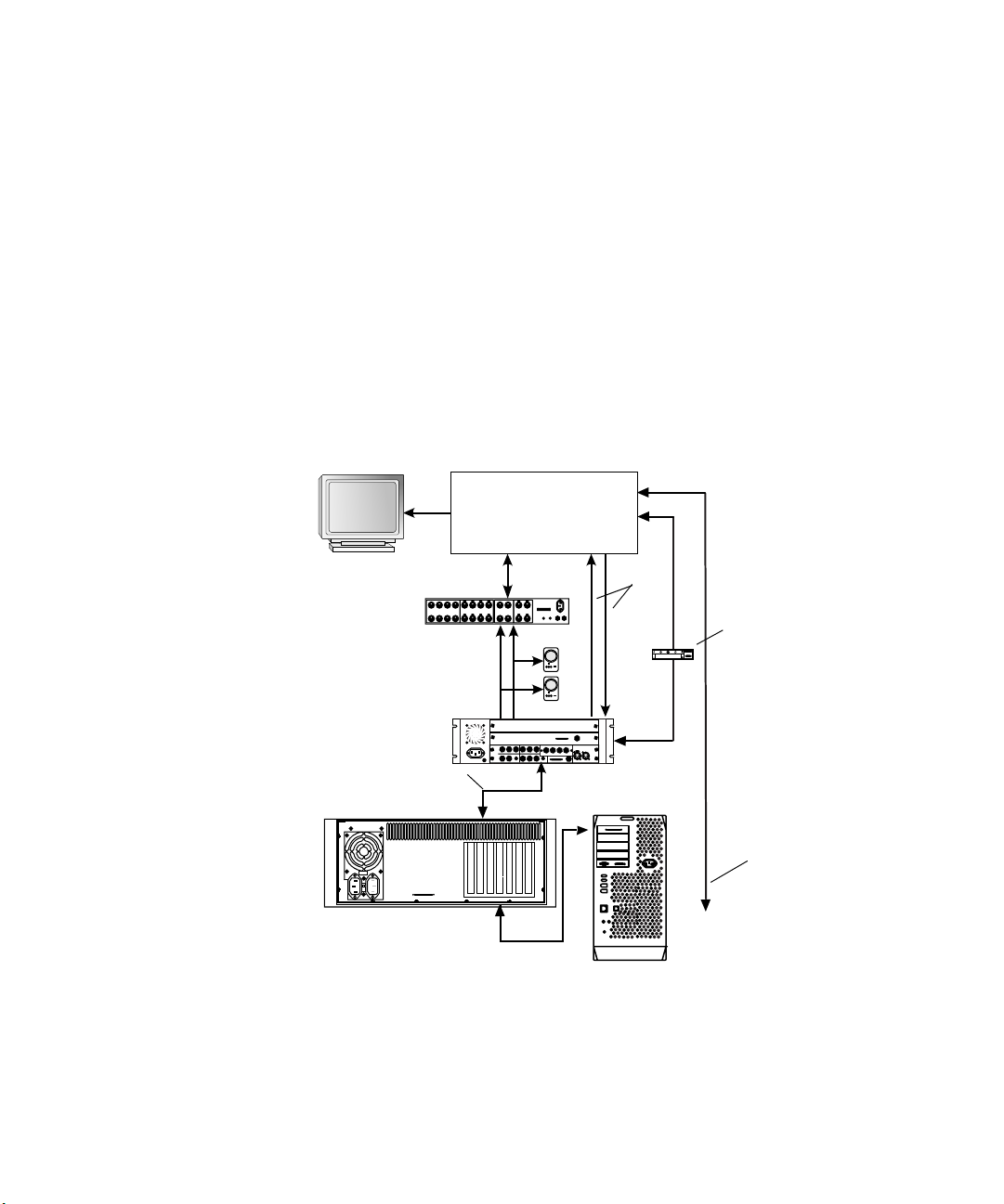
Connecting a Video Server
The Avid system controls the media going to and from the video server in
much the same way as it controls a video deck (see Figure 45). You should
use the same instructions that explain how to connect a video deck to the
Avid system when you connect the video server. It is assumed that you
know all the connections on your video server, so you only need to know
where to connect cables on the Avid system. For example, to connect
speakers see “Two-Channel Audio I/O Board Connectors” on page 69, or
to connect the black burst generator see “Connecting the Black Burst
Generator (BBGen)” on page 78. Figure 45 assumes you have the optional
Avid PCI Extender.
Video server
1234567
1-2
5-6
1234567
Eight-channel audio device
ANALOG OUT ANALOG IN ASE/EBU OUT ASE/EBU IN
8
8
3-4
7-8
Connecting a Video Server
Video
COMPUTER
1-2
5-6
3-4
7-8
SLAVE CLOCK
S/PDIF
S/PDIF
IN OUT
OUT
IN
R
BB1 BB2 BB3
L
Black burst generator
Avid system
Slave Clock
Meridien I/O box
Video and audio
IN
ININ
COMPONENT
IN
COMPOSITE
REF
8 channel
In
OUT 1 OUT 2 OUT 3IN
LTC
OUT
Y
B-Y
R-Y B-Y
Y
R-Y
DIGITAL VIDEO
SLAVE CLOCK
SYSTEM
OUT
IN
S-VIDEO
COMPOSITE
OUT 1
OUT
IN / OUT
S-VIDEO
OUT 3
OUT
OUT 2
Figure 45 Connecting a Video Server
Remote control
from
USB-to-serial adapter
97
Page 98

Chapter 4 Connecting Audio and Video Equipment
98
Page 99

Chapter 5
Connecting Serial and MIDI Port Devices
Avid systems support the connection of two different MIDI fader
controllers (fader controller), a Yamaha
JL Cooper Media Control Station3 (MCS3) jog/shuttle wheel (jog/shuttle
wheel). The fader controllers and the 01V mixer connect to the USB-toMIDI converter attached to the USB hub (see “Connecting the USB Hub”
on page 48), while the jog/shuttle wheel connects to the USB-to-serial
adapter attached to the USB hub using a female-to-female adapter and a
serial remote deck cable. The two fader controllers are the JL Cooper
FaderMaster Pro
recording automation gain using the MIDI features of the 01V mixer.
This chapter contains the following sections:
• Connecting JL Cooper Fader Controllers
• Connecting the Yamaha 01V Mixer
• Connecting the JL Cooper Jog/Shuttle Wheel
• Connecting a VTR Emulator Cable
™
and the JL Cooper MCS-3000X. Avid supports
®
01V mixer (01V mixer), and a
Page 100

Chapter 5 Connecting Serial and MIDI Port Devices
Connecting JL Cooper Fader Controllers
Your Avid system supports the FaderMaster Pro and the MCS-3000X fader
controllers. Both of the fader controllers connect to a USB-to-MIDI
converter that connects to the USB hub on the G4 platform. To initialize
and test your JL Cooper fader controllers, see either the editing guide or
user’s guide for your system.
Fader controller connections are shown for both the new MCS-3000X and
the FaderMaster Pro (see Figure 46 and Figure 47).
There are two major differences between the two fader controllers:
• The MCS-3000X has a four-position switchpack that is not on the
FaderMaster Pro.
• The MIDI IN and MIDI OUT are in opposite positions in the
MCS-3000X and the FaderMaster Pro.
To connect the fader controllers:
You can use In B and
Out B on the rear of the
USB-to-MIDI
converter instead of
In A and Out A, but
you need to reconfigure
the ports using the
software explained in
the release notes.
100
1. Quit any open applications.
2. Shut down the Avid system in a normal manner.
3. Make sure your USB-to-MIDI converter is connected to the USB hub
as explained in “Connecting the USB-to-MIDI Converter” on page 51.
4. If you are cabling the MCS-3000X, set switch 4 to the ON (down)
position. The switch is upside down on the MCS-3000X (see
Figure 46).
5. Locate two MIDI cables with 5-pin DIN connectors.
6. Plug one end of the first MIDI cable into the In A connector of the
USB-to-MIDI converter (see Figure 48), and the other end of the cable
into the MIDI OUT connector of the fader controller.
7. Plug one end of the second MIDI cable into the Out A
connector of the USB-to-MIDI converter, and the other end of the
cable into the MIDI IN connector of the fader controller.
8. The button on the front of the USB-to-MIDI converter must be In, (see
Figure 48).
 Loading...