

Page 1

PMCtendo SZ
Pilz Motion Control
OperatingManual1002405EN03
Page 2

Preface
Thisdocumentisatranslationoftheoriginaldocument.
AllrightstothisdocumentationarereservedbyPilzGmbH&Co.KG.Copiesmaybemade
forinternalpurposes.Suggestionsandcommentsforimprovingthisdocumentationwillbe
gratefullyreceived.
Pilz®,PIT®,PMI®,PNOZ®,Primo®,PSEN®,PSS®,PVIS®,SafetyBUSp®,
SafetyEYE®,SafetyNETp®,thespiritofsafety®areregisteredandprotectedtrademarks
ofPilzGmbH&Co.KGinsomecountries.
SDmeansSecureDigital
Page 3

Table of contents
Table of contents
1 Introduction . . . . . . . . . . . . . . . . . . . . . . . . . . . . .
1.1 Purpose of the manual. . . . . . . . . . . . . . . . . . . . . . . . . . . . . .
1.2 Further support . . . . . . . . . . . . . . . . . . . . . . . . . . . . . . . . . . .
1.3 Modifications . . . . . . . . . . . . . . . . . . . . . . . . . . . . . . . . . . . . .
2 Notes on Safety . . . . . . . . . . . . . . . . . . . . . . . . . .
2.1 Warranty and liability . . . . . . . . . . . . . . . . . . . . . . . . . . . . . . .
2.2 Component part of the product . . . . . . . . . . . . . . . . . . . . . . .
2.3 Operation in accordance with its intended use . . . . . . . . . . .
2.4 Qualified personnel . . . . . . . . . . . . . . . . . . . . . . . . . . . . . . . .
2.5 Working on the machine . . . . . . . . . . . . . . . . . . . . . . . . . . . .
2.6 Disposal . . . . . . . . . . . . . . . . . . . . . . . . . . . . . . . . . . . . . . . . .
2.7 Directives and norms . . . . . . . . . . . . . . . . . . . . . . . . . . . . . . .
2.8 Presentation of notes on safety . . . . . . . . . . . . . . . . . . . . . . .
3 Description . . . . . . . . . . . . . . . . . . . . . . . . . . . . . .
6
6
6
6
7
7
7
7
8
8
8
8
9
11
3.1 PMCtendo SZ servo motors. . . . . . . . . . . . . . . . . . . . . . . . . .
3.1.1 Type label . . . . . . . . . . . . . . . . . . . . . . . . . . . . . . . .
3.1.2 Order reference. . . . . . . . . . . . . . . . . . . . . . . . . . . .
3.2 Drive controller. . . . . . . . . . . . . . . . . . . . . . . . . . . . . . . . . . . .
3.3 Feedback . . . . . . . . . . . . . . . . . . . . . . . . . . . . . . . . . . . . . . .
3.4 Dynamic performance . . . . . . . . . . . . . . . . . . . . . . . . . . . . . .
3.5 Operating mode . . . . . . . . . . . . . . . . . . . . . . . . . . . . . . . . . . .
3.6 Thermal winding protection . . . . . . . . . . . . . . . . . . . . . . . . . .
3.7 Cooling. . . . . . . . . . . . . . . . . . . . . . . . . . . . . . . . . . . . . . . . . .
3.8 Holding brake. . . . . . . . . . . . . . . . . . . . . . . . . . . . . . . . . . . . .
3.8.1 Motor holding brake . . . . . . . . . . . . . . . . . . . . . . . .
3.8.2 Brake test and grinding . . . . . . . . . . . . . . . . . . . . . .
3.9 Motor shaft and bearings . . . . . . . . . . . . . . . . . . . . . . . . . . . .
4 Transportation and storage. . . . . . . . . . . . . . . . .
11
12
13
14
14
14
14
15
15
15
15
16
16
17
Operating Manual PMCtendo SZ
1002405-EN-03
3
Page 4

Table of contents
4.1 Transportation . . . . . . . . . . . . . . . . . . . . . . . . . . . . . . . . . . . .
4.2 Storage. . . . . . . . . . . . . . . . . . . . . . . . . . . . . . . . . . . . . . . . . .
5 Installation . . . . . . . . . . . . . . . . . . . . . . . . . . . . . .
5.1 Installation Location . . . . . . . . . . . . . . . . . . . . . . . . . . . . . . . .
5.2 Install motor . . . . . . . . . . . . . . . . . . . . . . . . . . . . . . . . . . . . . .
6 Electrical installation . . . . . . . . . . . . . . . . . . . . . .
6.1 General information . . . . . . . . . . . . . . . . . . . . . . . . . . . . . . . .
6.1.1 Wiring . . . . . . . . . . . . . . . . . . . . . . . . . . . . . . . . . . .
6.1.2 Earthing, shielding and EMC. . . . . . . . . . . . . . . . . .
6.1.3 Selecting the cables . . . . . . . . . . . . . . . . . . . . . . . .
6.1.4 speedtec® and springtec® plug connector . . . . . . .
6.2 Servo motor and motor brake . . . . . . . . . . . . . . . . . . . . . . . .
6.2.1 Power cable . . . . . . . . . . . . . . . . . . . . . . . . . . . . . .
6.2.2 Assignment: Motor and power cable . . . . . . . . . . . .
17
17
18
18
19
21
21
21
22
23
23
26
26
28
6.3 Feedback . . . . . . . . . . . . . . . . . . . . . . . . . . . . . . . . . . . . . . .
6.4 External fan . . . . . . . . . . . . . . . . . . . . . . . . . . . . . . . . . . . . . .
6.5 Water cooling . . . . . . . . . . . . . . . . . . . . . . . . . . . . . . . . . . . . .
7 Commissioning . . . . . . . . . . . . . . . . . . . . . . . . . .
7.1 Check installation. . . . . . . . . . . . . . . . . . . . . . . . . . . . . . . . . .
7.2 Check connection . . . . . . . . . . . . . . . . . . . . . . . . . . . . . . . . .
7.3 Put into operation. . . . . . . . . . . . . . . . . . . . . . . . . . . . . . . . . .
8 Service . . . . . . . . . . . . . . . . . . . . . . . . . . . . . . . . .
8.1 Maintenance . . . . . . . . . . . . . . . . . . . . . . . . . . . . . . . . . . . . .
8.2 In the event of disruptions . . . . . . . . . . . . . . . . . . . . . . . . . . .
8.3 Replace motor . . . . . . . . . . . . . . . . . . . . . . . . . . . . . . . . . . . .
9 Technical data. . . . . . . . . . . . . . . . . . . . . . . . . . . .
9.1 Ambient conditions. . . . . . . . . . . . . . . . . . . . . . . . . . . . . . . . .
9.2 Device Features. . . . . . . . . . . . . . . . . . . . . . . . . . . . . . . . . . .
30
31
31
32
32
33
34
36
36
37
38
39
39
39
Operating Manual PMCtendo SZ
1002405-EN-03
9.3 Electrical Data . . . . . . . . . . . . . . . . . . . . . . . . . . . . . . . . . . . .
9.4 Cooling. . . . . . . . . . . . . . . . . . . . . . . . . . . . . . . . . . . . . . . . . .
40
40
4
Page 5

Table of contents
9.4.1 Convection cooling . . . . . . . . . . . . . . . . . . . . . . . . .
9.4.2 External fan . . . . . . . . . . . . . . . . . . . . . . . . . . . . . . .
9.4.3 Water cooling . . . . . . . . . . . . . . . . . . . . . . . . . . . . .
9.5 Feedback . . . . . . . . . . . . . . . . . . . . . . . . . . . . . . . . . . . . . . .
9.6 Holding brake. . . . . . . . . . . . . . . . . . . . . . . . . . . . . . . . . . . . .
9.7 Thermal winding protection . . . . . . . . . . . . . . . . . . . . . . . . . .
9.8 Derating . . . . . . . . . . . . . . . . . . . . . . . . . . . . . . . . . . . . . . . . .
9.8.1 Installation altitude . . . . . . . . . . . . . . . . . . . . . . . . .
9.8.2 Ambient temperature. . . . . . . . . . . . . . . . . . . . . . . .
9.9 Type-specific data . . . . . . . . . . . . . . . . . . . . . . . . . . . . . . . . .
9.9.1 Inertia . . . . . . . . . . . . . . . . . . . . . . . . . . . . . . . . . . .
9.9.2 Weight . . . . . . . . . . . . . . . . . . . . . . . . . . . . . . . . . . .
9.9.3 Permitted shaft load . . . . . . . . . . . . . . . . . . . . . . . .
9.9.4 Voltage limit curves . . . . . . . . . . . . . . . . . . . . . . . . .
40
40
41
42
43
46
47
47
48
49
62
63
64
70
9.9.5 Key safety-related indicators. . . . . . . . . . . . . . . . . .
10 Glossary . . . . . . . . . . . . . . . . . . . . . . . . . . . . . . . .
79
80
Operating Manual PMCtendo SZ
1002405-EN-03
5
Page 6

1 Introduction
1Introduction
1.1 Purpose of the manual
This operating manual describes the servo motors PMCtendo SZ. It includes information
about, transport, storage, installation, connection, commissioning, service and disposal.
Please also refer to the documentation for the servo amplifier.
1.2 Further support
If you have any queries that are not covered in this document, you can find more information at www.pilz.com
1.3 Modifications
No. Versi on Date Change
1002504 01 0
1002504 02 09/2012 Update: Feedback system
1002504 03 03/2014 • Additions:
First edition
7/2012
Motor types SZ3x and SZ8x
Type keys
Directives and standards
springtec® plug connector
Type-specific data
Characteristic safety values
• Updates:
Rating plate
Power cable
Feedback connection
External fan
Thermal winding protection
Electrical installation
Brake data, brake moment of inertia values
Number of motor poles
Formula symbols
Operating Manual PMCtendo SZ
1002405-EN-03
6
Page 7

2 Notes on Safety
2 Notes on Safety
2.1 Warranty and liability
The devices can represent a source of danger. Therefore observe
• the safety guidelines, technical rules and regulations given in the following sections
•and points.
Warranty and liability claims will be void if
• the product has not been used for its intended purpose,
• the damage is attributable to a failure to observe the operation instruction,
• the operating personnel has not been properly trained, or
• modifications of any kind have been made.
2.2 Component part of the product
The technical documentation is a component part of a product.
• Since the technical documentation contains important information, always keep it
handy in the vicinity of the device until the machine is disposed of.
• If the product is sold, disposed of, or rented out, always include the technical documentation with the product.
2.3 Operation in accordance with its intended use
The servo motors are intended for installation in machines or systems or for assembly
with other components in a machine They must be operated in conjunction with suitable
and correctly configured servo amplifiers (e.g. PMCtendo DD4, PMCtendo DD5 or
PMCprotego D).
The thermal motor protection integrated in the motor winding must be monitored and
evaluated.
The following is deemed improper use:
• direct connection to the mains power supply,
• any component, technical or electrical modification,
• use outside the areas described in this manual,
• use outside the documented technical details.
Operating Manual PMCtendo SZ
1002405-EN-03
7
Page 8

2 Notes on Safety
2.4 Qualified personnel
Devices may cause residual risks. For this reason, all work on the devices as well as operation and disposal must only be performed by qualified personnel who are aware of the
possible dangers.
Qualified personnel are persons who have acquired the authorisation to perform these
activities by
• Training from specialists and/or
• Instruction from specialists
In addition, they must have
• read,
• understood and
• observed the applicable regulations, legal provisions, rules and standards and existing technical documentation including the safety information contained in it.
2.5 Working on the machine
Apply the 5 safety rules in the order stated before working on the machine:
1. Activate. Make sure the auxiliary circuits are activated.
2. Secure against unintentional restart.
3. Make sure no voltage is present.
4. Ground and short-circuit.
5. Cover or enclose adjacent live parts.
2.6 Disposal
Please comply with the latest national and regional regulations! Dispose of the individual
parts separately depending on their nature and currently valid regulations such as, for
example:
• Electronic scrap (PCBs)
• Plastic
• Sheet metal
• Copper
•Aluminum
2.7 Directives and norms
The servo motors meet the following guidelines and norms
• Directive 2006/95/EC (Low Voltage Directive)
• Directive 2004/108/EC (Directive on Electromagnetic Compatibility)
• DIN EN 60204-1 version 2007
• DIN EN 60034-1 version 2011
Operating Manual PMCtendo SZ
1002405-EN-03
8
Page 9

2 Notes on Safety
• DIN EN 60034-5 version 2007
• DIN EN 60034-6 version 1996
• DIN EN 60034-9 version 2008
• DIN EN 60034-14 version 2008
• UL and CSA approval
All motors are supplied with certifications as "Recognized Component Class 155 (F)
motor insulation system".
UL approval is registered with Underwriters Laboratories USA under UL File Number
E182088 (N), Classes OBJY2 and OBJY8, Component-Systems, Electrical Insulation. UL certification is needed mainly for the use of motors and geared motors on
the US market. But, also in many countries UL approval is considered a special mark
of quality.
2.8 Presentation of notes on safety
IMPORTANT
IMPORTANT
This means that material damage may occur
if the safety precautions stated are not observed.
NOTICE!
CAUTION
This means that a minor injury may occur.
if the safety precautions stated are not observed.
WARNING!
Warning
means that there may be a serious danger of death
if the stated precautionary measures are not taken.
Operating Manual PMCtendo SZ
1002405-EN-03
9
Page 10

2 Notes on Safety
DANGER!
Danger
means that serious danger of death exists
if the stated precautionary measures are not taken.
INFO
refers to important information about the product or serves to emphasize a
section in the documentation to which the reader should pay special attention.
Operating Manual PMCtendo SZ
1002405-EN-03
10
Page 11
3 Description
3 Description
3.1 PMCtendo SZ servo motors
The PMCtendo SZ synchronous servo motors have a very short design achieved thanks
to an optimized winding technology. This feature makes it possible to manufacture the
stator windings with the highest possible copper fill factor. With this technology and further optimizations in the mechanical parts it has been possible to shorten the length of
the motor by almost half without reducing the power output.
Operating Manual PMCtendo SZ
1002405-EN-03
11
Page 12

3 Description
3.1.1 Type label
Description Value in example Meaning
Year of
YOM 2014 Year of manufacturing 2014
Manufacturing
Type PMCtendo SZ.31/0/1/2/7/K/H/60/00 Order references
SN 7008874/001/000/010/00 Serial number
Ident.No. xxxxxxx Identification number
M
0,95 Nm Standstill torque: Constant standstill torque for
0
250 min
M
0,89 Nm Rated torque; highest constant torque of the motor for
N
a rated speed n
I
2,02 A Standstill current: I
0eff
I
1,93 A Rated current: Constant current at MN ± 5 % and
N
n
K
40 V/1000 rpm EMC voltage stability: Peak value of the chained, in-
E M
± 5 %
N
-1
± 5 %
± 5 %
N
is the current flowing at M0
0eff
duced voltage for an operating voltage (∆T = 100 K)
when idle running as generator
K
1,35 Nm/A Torque constant: Constant in the entire functional
M ,N
range of a motor
n 6000 rpm Rated speed n
N
Insul.-class F Thermal class acc. to EN 60034/VDE 0530
IP 56 Protection class
th.prot. PTC thermistor 145 °C Thermal winding protection by PTC drilling
encoder ECI 1118-G2 EnDat 2.2 ST Feedback system
Operating Manual PMCtendo SZ
1002405-EN-03
12
Page 13
3 Description
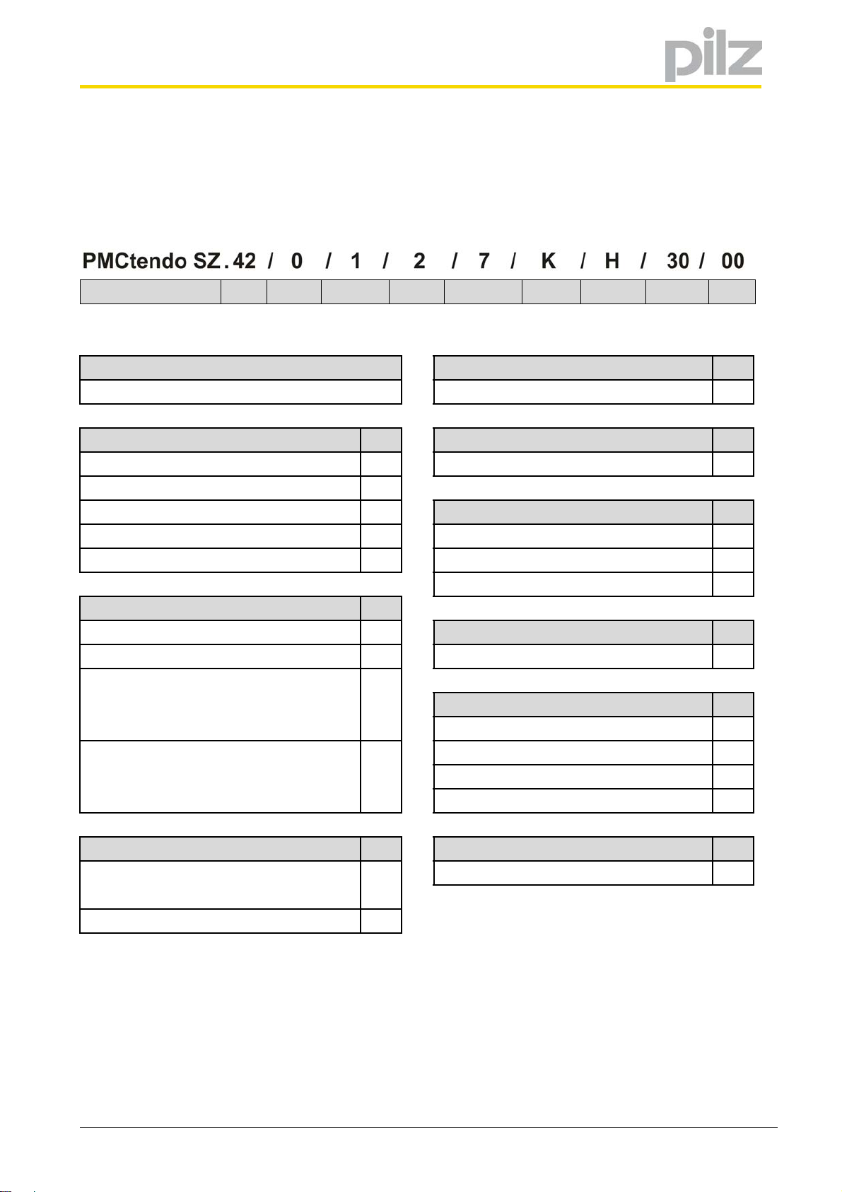
3.1.2 Order reference
1 2 3 4 5 6 7 8 9 10
Product name Size Brake Feedback Design Connection Cooling Voltage Speed Option
1 Product name 5 Design Code
PMCtendo SZ B5, smooth shaft 2
2 Size Code 6 Connection Code
PMCtendo SZ3x 3x Feedback 7
PMCtendo SZ4x 4x
PMCtendo SZ5x 5x
PMCtendo SZ7x 7x Convection K
PMCtendo SZ8x 8x External fan (not applicable for SZ.3x) F
3 Brake and dynamic design Code
Without brake and dynamic design 0
With brake and dynamic design 1 400 V (UZK = 540 V) H
Without brake, with increased mass moment 2
of inertia
(not applicable for SZ.3x, SZ.51, SZ.71) 2000 min
With brake, with increased mass moment 3 3000 min
of inertia 4500 min
(not applicable for SZ.3x, SZ.51, SZ.71) 6000 min
4 Feedback Code 10 Option Code
Single-turn EnDat® 2.2 ECI1118-G2 1 Standard 00
inductive
Multi-turn EnDat® 2.2 EQN1135 optical 2
7 Cooling Code
Water cooling (not applicable for SZ.3x) W
8 Voltage Code
9 Speed a) Code
-1
20
-1
30
-1
45
-1
60
a) See section Type-specific data
Operating Manual PMCtendo SZ
1002405-EN-03
13
Page 14

3 Description
3.2 Drive controller
The servo motors must be operated in conjunction with a servo amplifier with speed,
torque or position control, e.g. PMCtendo DD4, PMCtendo DD5 or PMCprotego D.
Servo motors, cables and servo amplifiers should always be regarded as one cohesive
system. The most important selection criteria are:
• Constant standstill torque M
• Constant standstill current I
• Rated speed n
• Mass moment of inertia of motor and load J [kgcm
• Effective torque (calculated) M
• Regenerative energy in braking mode
• Overload capacity
•EMC
[min-1]
N
[Nm]
0
0 eff
[A]
eff
[Nm]
2
]
When selecting the servo amplifier, please consider both the static and the dynamic load
(acceleration/ braking).
3.3 Feedback
PMCtendo SZ motors may be fitted with the following feedback systems:
• Single-turn EnDat
• Multi-turn EnDat
Single-turn feedback systems provide an absolute position within one revolution while
multi-turn feedback systems specify an absolute position over a number of revolutions.
®
2.2 ECI1118-G2 inductive,
®
2.2 EQN1135 optical.
3.4 Dynamic performance
The PMCtendo SZ motors are designed as standard for applications with high dynamic
performance, i.e. they have the lowest possible mass moment of inertia. As an option the
servo motors can be supplied with an increased mass moment of inertia in order to optimize the inertia ratio between motor and load.
3.5 Operating mode
The servo motors are designed for continuous operation. This corresponds to operating
mode S1 (in accordance with DIN EN 60 034-1).
Operating Manual PMCtendo SZ
1002405-EN-03
14
Page 15

3 Description
3.6 Thermal winding protection
The servo motors have a thermal winding protection, which protects the stator winding
from damage in the case of constant overload.
The PMCtendo SZ motors are fitted with PTC drilling as standard. If the motor temperature reaches a critical level, the ohmic resistance of the PTC resistors increases abruptly
and this indicates motor overload.
INFO
Each thermal winding protection must be monitored and evaluated by the
servo amplifier or an external triggering device.
3.7 Cooling
As standard the servo motors are dimensioned for convection cooling.
In order to increase the continuous torque output or continuous power output, the servo
motors can be fitted as an option with external fan systems (IP44). External fan systems
can be retrofitted.
In applications requiring a higher protection class than IP44 or a lower noise level, the
servo motors can be water-cooled in the A-side flange.
3.8 Holding brake
WARNING!
Danger to life!
The motor brake is not a safety brake!
Check whether additional safety measures must be taken, e. g. when remaining un-
der suspended loads.
3.8.1 Motor holding brake
The servo motors may be supplied with a built-in permanent magnet brake for backlashfree holding of the motor shaft. This blocks the rotor when the supply voltage is switched
off. The brake has electromechanical ventilation: The applied voltage generates a magnetic field that counteracts the permanent magnetic field and neutralises its influence.
Operating Manual PMCtendo SZ
1002405-EN-03
15
Page 16

3 Description
As the servo motors can be quickly and actively braked by appropriate setpoint settings
at the servo amplifier, the built-in brakes function as a holding brake. Additional brakes
must be provided for braking when the motor is turning, e.g. for an emergency stop.
3.8.2 Brake test and grinding
If a brake does not perform any friction work over an extended period of time, its friction
factor may change due to accumulations of flash rust or vapors resulting from high motor
temperatures. It is also possible that a slight material distortion may be noted as the result of major temperature fluctuations.
To ensure the functional safety of brakes, including the case of gravity-loaded vertical axes, the brakes must be subjected to brake tests at regular intervals.
Testing brakes
Load the brake with 1.3 times the load torque. Make certain that the suspended load of
a vertical axis is already exerting torque on the motor when it is at a standstill.
Regrind the brake
If the tested braking torque differs from the required value, a brake can be reground.
To do this, run the motor at maximum 20 rpm.
Release and close the brake once per second so that the motor is required to work
against the closed brake for about 0.7 seconds.
Repeat these steps in the reverse direction of rotation after about 20 cycles. If the nominal holding torque of the brake is still not correct after this regrinding, repeat the entire
process. If the nominal holding torque of the brake has still not been reestablished after
grinding five times, check for other factors that could be responsible for the deviating
nominal holding torque of the brake, for example if the wear limit has been reached.
Depending on the relevant servo inverter types, the grinding routine can also be automated. For further details see the corresponding documentation.
3.9 Motor shaft and bearings
The servo motors have a smooth shaft end (DIN 6885) on the drive side. With a friction
connection, torque transfer must be achieved through surface pressure. This guarantees
a safe, backlash-free force transfer.
The bearings are designed as ball bearings with permanent lubrication and non-contact
seals.
Operating Manual PMCtendo SZ
1002405-EN-03
16
Page 17

4 Transportation and storage
4 Transportation and storage
4.1 Transportation
Secure the shafts and bearings of the servo motor against impact when transporting. Use
eye bolts (if provided) and suitable slings when transporting the servo motor. Only lift the
servo motor at the eye bolts without additional attachments. Never transport the servo
motor on the fan guards or the angular flange sockets.
4.2 Storage
Store the servo motors in enclosed, dry spaces. Storage on the fan guards is not permitted.
If the servo motors are protected from all harmful environmental influences, brief storage
in open-air spaces with roofing is permitted.
Make sure that no condensation forms during storage, e.g. because of extreme temperature fluctuations with a high level of humidity.
Protect the motor shaft from corrosion when storing over an extended period. Note that
the insulation resistance of the winding must be checked after storing over an extended
period.
Operating Manual PMCtendo SZ
1002405-EN-03
17
Page 18

5 Installation
5Installation
WARNING!
Electric shock hazard!
Risk of serious injury from contact with live parts!
Observe the 5 safety rules (see chapter 2.5 Working on the machine).
Disconnect the motor from the power supply before carrying out work!
Ensure that the motor shaft is at a standstill before carrying out work! A rotating rotor
can generate high voltages at the terminals.
Switch off the power supplies to all connected devices and devices to be connected.
Note that dangerously high voltages can still occur at the servo amplifier even 10
minutes after switching off the power supply due to the residual charge of the DC link
capacitors.
Cover all open electrical connections, e.g with protective caps.
Cordon off the installation area according to the safety regulations, e.g. with barriers,
warning signs.
WARNING!
Burns!
The surface temperature of the servo motor can exceed 65 °C during operation!
Safety measures should be put in place to protect against contact during operation,
whether accidental or intentional.
5.1 Installation Location
The following preconditions apply for the installation location:
• The installation location must be free from aggressive substances and electrically
conductive atmospheres.
• The substructure must be level, vibration-free and torsionally rigid.
• Ensure adequate heat dissipation. Ensure compliance with the admissible ambient
temperature. If necessary, cool the servo motor additionally, e.g. using an external
fan.
• Observe the minimum clearance to the air intake of an external fan.
Operating Manual PMCtendo SZ
1002405-EN-03
18
Page 19

5 Installation
Motor External fan Minimum distance x
SZ.4x FL4 20
SZ.5x FL5 20
SZ.7x FL7 30
SZ.8x FL8 30
The following installation positions are admissible:
Admissible installation positions
IM B5 IM V1 IM V3
Particularly in installation position IM V3, ensure that no liquids from attachments can run
into the motor bearings.
Fmin
[mm]
5.2 Install motor
IMPORTANT
Material damage!
Impact and other forces can cause damage to the bearings, feedback system and motor
shaft.
Do not hit the motor shaft or motor housing with a hammer or other tools.
Do not apply any pressure, impact or high acceleration to the motor.
Use backlash-free, frictionally engaged chucks or clutches.
Always use the tightening thread provided in the motor shaft to fit or remove clutches,
gears or belt pulleys. Use suitable tools!
Operating Manual PMCtendo SZ
1002405-EN-03
19
Page 20

5 Installation
Material damage!
Solvent damages the sealing lips of the shaft seal rings.
Make sure that solvent can not come into contact with the sealing lips of the shaft
Prepare the motor for installation
• Check the motor for transport damage. Never install a servo motor that shows clear
• Check the insulation resistance of the winding of the motor after storage.
• Thoroughly remove anti-corrosion agents and/or contamination on the motor shaft.
• If possible, warm up the drive elements, e.g. belt pulley
• Make sure that the paintwork of the servo motors is not damaged.
IMPORTANT
seal rings.
signs of damage!
This can be done using a standard solvent. Make sure that the solvent can not come
into contact with the sealing lips of the shaft seal rings, otherwise materials may be
damaged.
Install motor
• Align the clutch correctly. Misalignment can cause undue vibration and can damage
the ball bearings and clutch!
• Mechanical overdefinition of the motor shaft bearing should be avoided. A rigid clutch
and/or an external additional bearing (e.g. in the gear unit) can cause excess mechanical stress on the motor shaft.
• Prevent temperature-sensitive components coming into contact with the motor.
During operation, the surface temperature of the servo motor can exceed 65 °C!
• When removing the eye bolts after installation, permanently close the threaded hole
according to the protection class of the motor.
Operating Manual PMCtendo SZ
1002405-EN-03
20
Page 21

6 Electrical installation
6 Electrical installation
WARNING!
Electric shock hazard!
Risk of serious injury from contact with live parts!
Observe the 5 safety rules (see chapter 2.5 Working on the machine).
Disconnect the motor from the power supply before carrying out work!
Ensure that the motor shaft is at a standstill before carrying out work! A rotating rotor
can generate high voltages at the terminals.
Switch off the power supplies to all connected devices and devices to be connected.
Note that dangerously high voltages can still occur at the servo amplifier even 10
minutes after switching off the power supply due to the residual charge of the DC link
capacitors.
Cover all open electrical connections, e.g with protective caps.
Cordon off the installation area according to the safety regulations, e.g. with barriers,
warning signs.
WARNING!
Uncontrolled movements of the servo motor can result in injury!
Incorrect wiring of the servo motor and/or feedback unit can trigger uncontrolled movements and result in material damage and/or personal injury.
All work must be carried out by specialists.
Observe the specifications in this operating manual and in the documentation of the
servo amplifier used.
Observe the applicable regulations.
6.1 General information
6.1.1 Wiring
Observe the regulations applicable for your machine or system when installing the electrical equipment, e.g. DIN IEC 60364 or DIN EN 50110.
Operating Manual PMCtendo SZ
1002405-EN-03
21
Page 22
6 Electrical installation
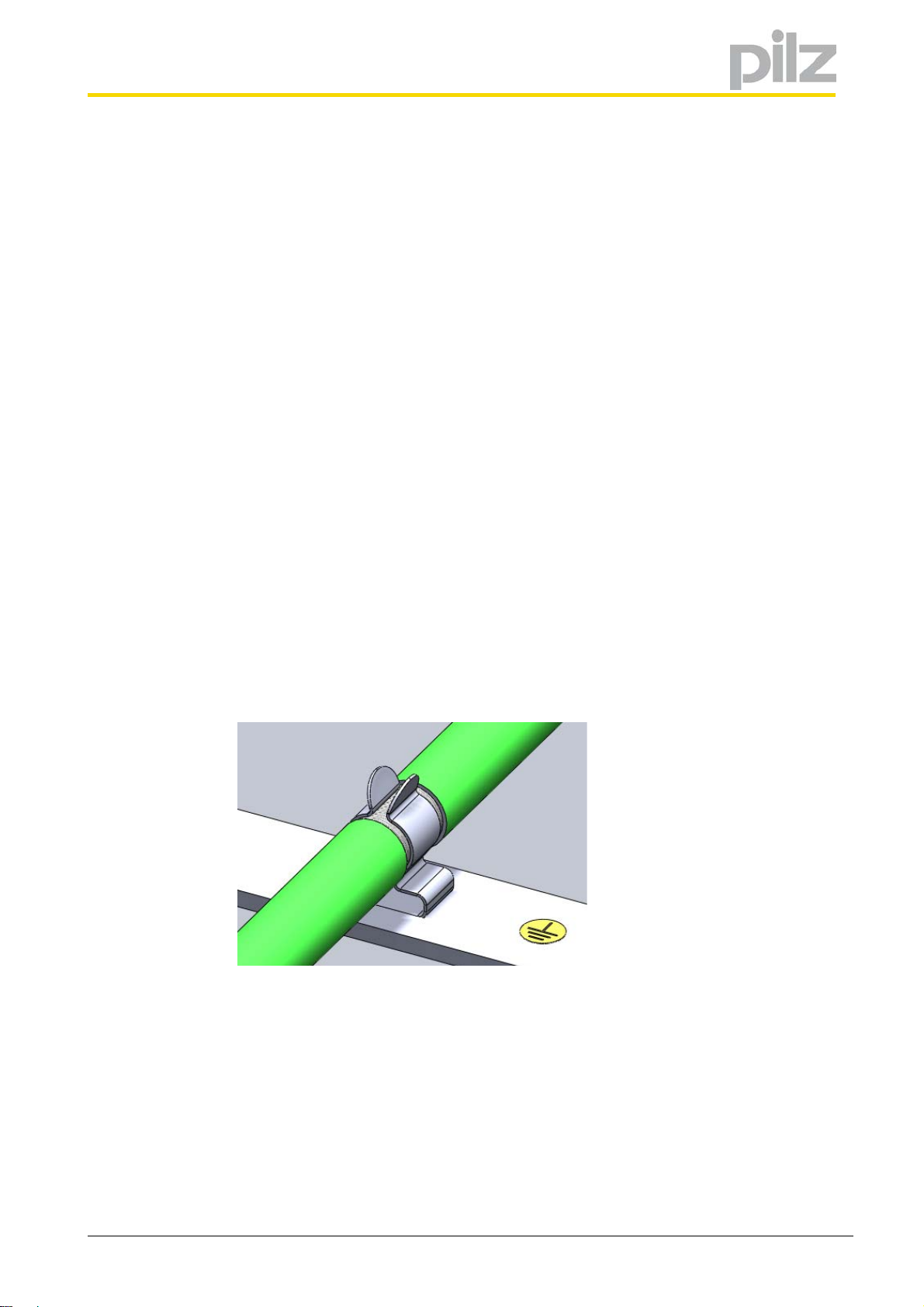
6.1.2 Earthing, shielding and EMC
Note the following points:
• On the servo motors, the connection to PE is established via the supply voltage cable
(see section 6.2 Servo motor and motor brake). For an additional earth in accordance
with DIN EN 60204-1, the motors have an earth connection attached and indicated
on the exterior.
• If necessary, use a toroidal core for the supply voltage cable, or a motor throttle close
to the servo amplifier. Please refer to the information stated in the operating manual
of the servo amplifier you are using.
• You will need shielded cable for data and control lines.
– Earth the inner and outer cable shield connections on both sides (e.g. on a bus
bar).
• You will need shielded cable for data and control lines.
– Earth the outer cable shield connection on both sides (e.g. on a bus bar).
– Earth the inner cable shield on the side of the servo amplifier (e.g. on a bus bar).
– If you are using longer cables and there is the possibility of transient currents,
these can be prevented by using equipotential bonding cables.
• Shields should be connected over a wide surface area (low impedance), using metallised connector housings or EMC-compliant cable screw connections.
• An appropriate connection material should be used to connect the cable shield to the
earth bar or bus bar (e.g. shielded terminals, see Fig. 6-1: ).
Fig. 6-1: Cable shield connection using a shielded terminal on the earth bar (reproduced
with permission from icotek GmbH, www.icotek.de)
Operating Manual PMCtendo SZ
1002405-EN-03
22
Page 23
6 Electrical installation
6.1.3 Selecting the cables
Note that motor, cables and servo amplifier each have electrical properties which influence one another. If not properly balanced, this can lead to inadmissibly high voltage
peaks at motor and servo amplifier.
Please note also the following points:
• Select the lead cross-sections according to the admissible continuous open-circuit
current of the motor. Observe also the documentation on the servo amplifier.
• If necessary, pay attention also to the trailability and torsional strength of the leads.
• The leads are connected to the servo motor by plug connectors. Cables are available
as accessories.
• For the choice of the cable cross-sections, see chapter 6.2 Servo motor and motor
brake.
• When using a motor brake, pay attention to the drop in the supply voltage on the lead.
• Observe the statutory regulations on EMC.
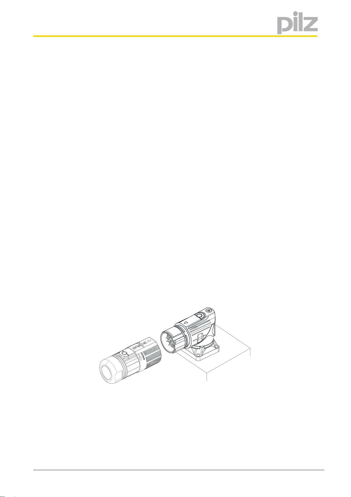
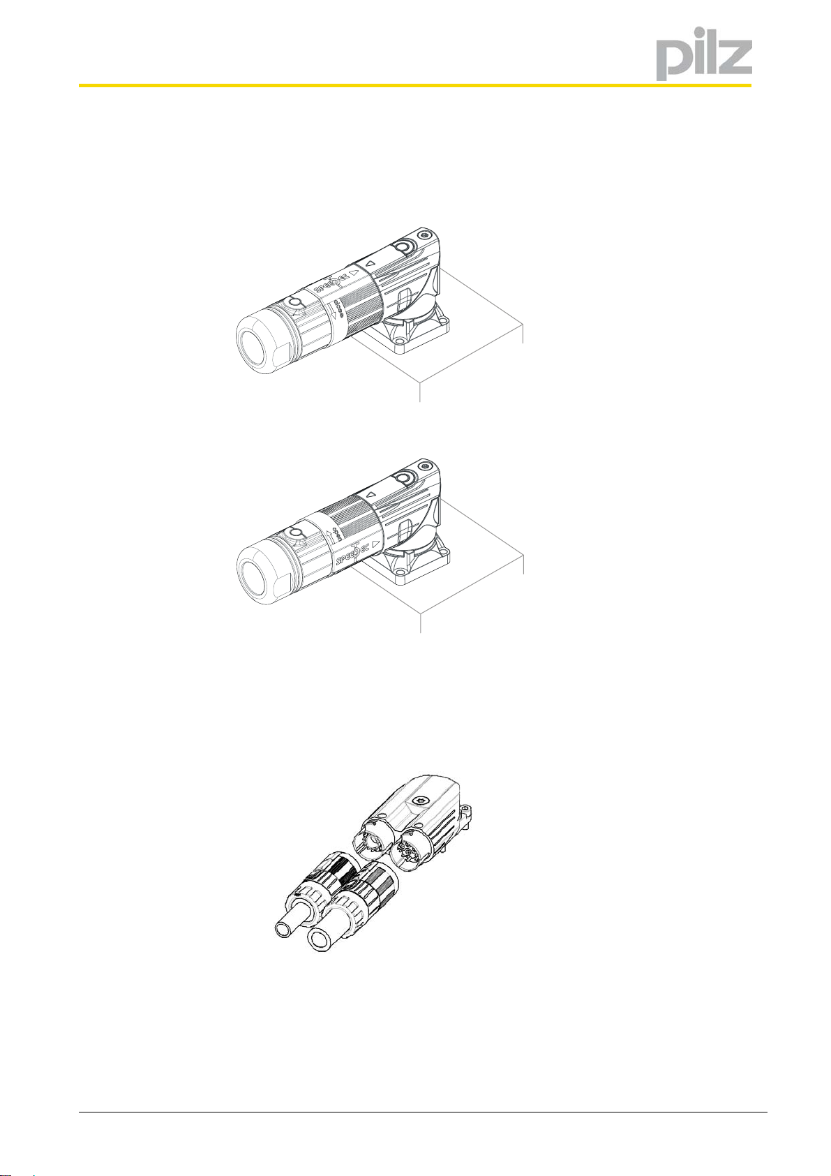
6.1.4 speedtec® and springtec® plug connector
The servo motors are fitted with speedtec angular flange sockets. A cable with a speed-
®
tec
plug connector is connected as follows.
Requirement: You have removed the protection caps from the angular flange sockets.
Connect the cable to the speedtec
1 Align the union nut so that the arrow faces the union nut and angular sock-
et:
®
plug connector
Operating Manual PMCtendo SZ
1002405-EN-03
23
Page 24
6 Electrical installation
2 Attach the union nut evenly on the angular socket:
3 Turn the screw cap of the union nut in the direction of "close" up to the limit
stop:
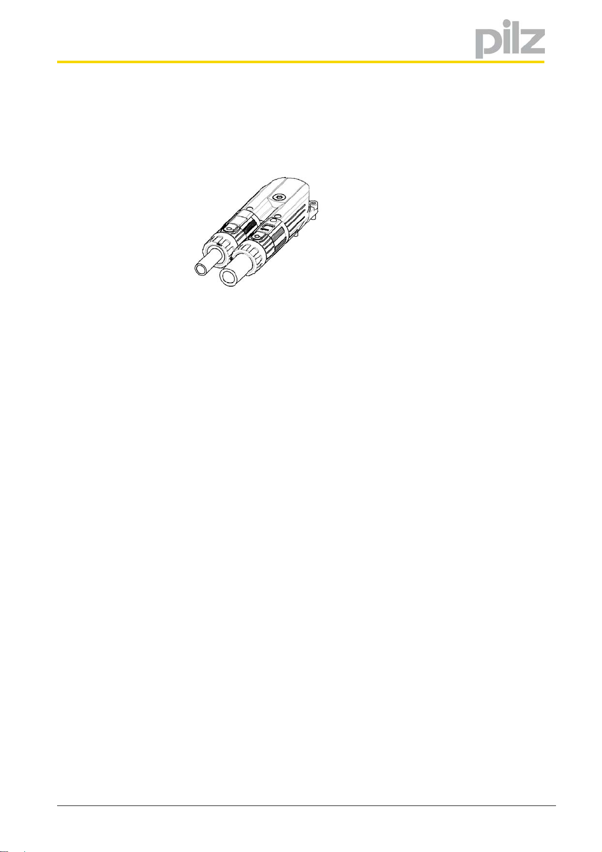
Connect the cable with springtec® plug connector
1 Align the respective union nuts of the green encoder plug and the orange
power connector so that the points on the union nuts and the angle connection socket are facing each other:
Operating Manual PMCtendo SZ
1002405-EN-03
24
Page 25
6 Electrical installation
2 Connect the union nuts directly onto the angle connection socket:
Operating Manual PMCtendo SZ
1002405-EN-03
25
Page 26
6 Electrical installation
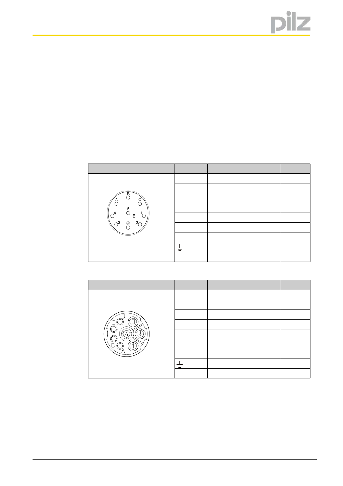
6.2 Servo motor and motor brake
6.2.1 Power cable
PMCtendo SZ servo motors will be connected to the drive controllers via the following
power cables (the colour specifications apply to the connection strands and are only relevant for the motor wiring).
Power cable – connector size con.15
Angular flange socket – motor Pin Signal Colour
A1U1 BK
B 1V1 BU
C1W1 RD
1
2
3 1BR+ (brake + 24 V
4 1BR– (brake 0 V) BK
PE GNYE
Housing Shield
Power cable – connector size con.23
Angular flange socket – motor Pin Signal Colour
A 1BR+ (brake + 24 V
B 1BR– (brake 0 V) BK
C
D
11U1 BK
31W1 RD
4 1V1 BU
PE GNYE
)RD
DC
)RD
DC
Operating Manual PMCtendo SZ
1002405-EN-03
Housing Shield
26
Page 27

6 Electrical installation
Power cable – connector sizes con.40, con.58
Angular flange socket – motor Pin Signal Colour
U1U1 BK
V1V1 BU
W1W1 RD
+ 1BR+ (brake + 24 VDC) RD
– 1BR– (brake 0 V) BK
1
2
PE GNYE
Housing Shield
Operating Manual PMCtendo SZ
1002405-EN-03
27
Page 28

6 Electrical installation
6.2.2 Assignment: Motor and power cable
Assignment of connector size and minimum cross-section of power cores.
INFO
Note that the following assignment of the connector size to the minimum
cross-section ø
PMCtendo SZ – convection-cooled (PMCtendo SZ.xx/.../K/...)
nN = 2000 min-1 nN = 3000 min-1 nN = 4500 min-1 nN = 6000 min-1
Motor
Connec-
tor size
ø
min
[mm2]
Connec-
tor size
SZ.31 — — con.15 1,0 — — con.15 1,0
refers to a maximum cable length of 100 m.
min
ø
min
[mm2]
Connec-
tor size
ø
min
[mm2]
Connec-
tor size
ø
[mm2]
min
SZ.32 — — con.15 1,0 — — con.15 1,0
SZ.33 — — con.15 1,0 — — con.15 1,0
SZ.41 — — con.15 1,5 — — con.23 1,5
SZ.42 — — con.23 1,5 — — con.23 1,5
SZ.44 — — con.23 1,5 — — con.23 1,5
SZ.51 — — con.23 1,5 — — con.23 1,5
SZ.52 — — con.23 1,5 — — con.23 1,5
SZ.53 — — con.23 1,5 — — con.23 1,5
SZ.55 — — con.23 1,5 con.23 1,5 — —
SZ.71 — — con.23 1,5 — — con.23 1,5
SZ.72 — — con.23 1,5 — — con.23 2,5
SZ.73 — — con.23 1,5 con.23 2,5 — —
SZ.75 — — con.40 2,5 con.40 4,0 — —
SZ.82 — — con.40 4,0 con.40 6,0 — —
SZ.83——con.406,0————
SZ.85con.4010,0——————
Operating Manual PMCtendo SZ
1002405-EN-03
28
Page 29

6 Electrical installation
PMCtendo SZ – externally ventilated (PMCtendo SZ.xx/.../F/...)
nN = 2000 min-1 nN = 3000 min-1 nN = 4500 min-1 nN = 6000 min-1
Motor
SZ.41 — — con.23 1,5 — — con.23 1,5
SZ.42 — — con.23 1,5 — — con.23 1,5
SZ.44 — — con.23 1,5 — — con.23 1,5
SZ.51 — — con.23 1,5 — — con.23 1,5
SZ.52 — — con.23 1,5 — — con.23 1,5
SZ.53 — — con.23 1,5 — — con.23 2,5
SZ.55 — — con.23 1,5 con.23 2,5 — —
SZ.71 — — con.23 1,5 — — con.23 1,5
SZ.72 — — con.23 1,5 — — con.23 4,0
SZ.73 — — con.23 2,5 con.23 4,0 — —
Connec-
tor size
ø
min
[mm2]
Connec-
tor size
ø
min
[mm2]
Connec-
tor size
ø
min
[mm2]
Connec-
tor size
ø
[mm2]
min
SZ.75 — — con.40 4,0 con.40 6,0 — —
SZ.82 — — con.40 6,0 con.40 10,0 — —
SZ.83——con.4010,0————
SZ.85con.5816,0——————
PMCtendo SZ – water-cooled (PMCtendo SZ.xx/.../W/...)
nN = 2000 min-1 nN = 3000 min-1 nN = 4500 min-1 nN = 6000 min-1
Motor
Connec-
tor size
ø
min
[mm2]
Connec-
tor size
ø
min
[mm2]
Connec-
tor size
ø
min
[mm2]
Connec-
tor size
ø
min
[mm2]
SZ.41 — — con.23 1,5 — — con.23 1,5
SZ.42 — — con.23 1,5 — — con.23 1,5
SZ.44 — — con.23 1,5 — — con.23 1,5
SZ.51 — — con.23 1,5 — — con.23 1,5
SZ.52 — — con.23 1,5 — — con.23 1,5
SZ.53 — — con.23 1,5 — — con.23 2,5
SZ.55 — — con.23 1,5 con.23 2,5 — —
SZ.71 — — con.23 1,5 — — con.23 1,5
SZ.72 — — con.23 1,5 — — con.23 4,0
SZ.73 — — con.23 2,5 con.23 4,0 — —
SZ.75 — — con.40 4,0 con.40 6,0 — —
SZ.82 — — con.40 6,0 con.40 10,0 — —
SZ.83——con.4010,0————
SZ.85con.5816,0——————
Operating Manual PMCtendo SZ
1002405-EN-03
29
Page 30

6 Electrical installation
6.3 Feedback
PMCtendo SZ servo motors will be connected to the feedback systems single-turn/multiturn EnDat® 2.2 optical/inductive via the following feedback cables (the colour specifications apply to the connection strands and are only relevant for the motor wiring).
Feedback cable – plug connector con.15
Angular flanged socket - motor Pin Signal Colour
1CLOCKVT
2
3
4PTC– WH
5 DATA/ PK
6DATA GY
7
8CLOCK/YE
9
10 0 V WHGN
11 PTC+ BK
12 0 V BNGN
Housing Shield
Feedback cable – plug connector con.23
Angular flanged socket - motor Pin Signal Colour
1CLOCKVT
2
3
4PTC– WH
5 DATA/ PK
6DATA GY
7
Operating Manual PMCtendo SZ
1002405-EN-03
8CLOCK/YE
9
10 0 V WHGN
11 PTC+ BK
12 Up BNGN
Housing Shield
30
Page 31

6 Electrical installation
A
A
1
2
3
6.4 External fan
The following plug connection for connecting the external fan is included with delivery.
Pin Signal
1L1
2N
3—
PE
6.5 Water cooling
Connect the water cooling to the hose connectors G1/8" (fittings). Connection is possible
on the connector side or opposite.
Observe the specifications for the cooling circuit, see section 9.4.3 Water cooling.
Operating Manual PMCtendo SZ
1002405-EN-03
31
Page 32

7 Commissioning
7 Commissioning
7.1 Check installation
WARNING!
Electric shock hazard!
Risk of serious injury from contact with live parts!
Observe the 5 safety rules (see chapter 2.5 Working on the machine).
Disconnect the motor from the power supply before carrying out work!
Ensure that the motor shaft is at a standstill before carrying out work! A rotating rotor
can generate high voltages at the terminals.
Switch off the power supplies to all connected devices and devices to be connected.
Note that dangerously high voltages can still occur at the servo amplifier even 10
minutes after switching off the power supply due to the residual charge of the DC link
capacitors.
Cover all open electrical connections, e.g with protective caps.
Cordon off the installation area according to the safety regulations, e.g. with barriers,
warning signs.
Installation
Check the installation and alignment of the servo motor.
Check the drive elements (clutch, gears, belt pulley)
for secure mechanical fitting and correct setting.
Check whether the motor surface is protected against
contact, whether accidental or intentional.
Check that contact with temperature-sensitive parts on
the motor has been prevented.
Check that the rotor of the servo motor can turn freely. If a motor brake is provided, this must be ventilated be-
—
—
Note:
Risk of burns or fire!
The surface temperature of the servo motor can exceed 65 °C during operation!
fore the test. Observe the polarity of the connections
when doing this!
Operating Manual PMCtendo SZ
1002405-EN-03
32
Page 33

7 Commissioning
7.2 Check connection
WARNING!
Electric shock hazard!
Risk of serious injury from contact with live parts!
Observe the 5 safety rules (see chapter 2.5 Working on the machine).
Disconnect the motor from the power supply before carrying out work!
Ensure that the motor shaft is at a standstill before carrying out work! A rotating rotor
can generate high voltages at the terminals.
Switch off the power supplies to all connected devices and devices to be connected.
Note that dangerously high voltages can still occur at the servo amplifier even 10
minutes after switching off the power supply due to the residual charge of the DC link
capacitors.
Cover all open electrical connections, e.g with protective caps.
Cordon off the installation area according to the safety regulations, e.g. with barriers,
warning signs.
WARNING!
Risk of injury from moving parts!
Make sure that
no persons are at risk due to start-up.
all protective and safety equipment is properly installed, even during commissioning
and test operation.
components attached to the drive are adequately protected against centrifugal forces
(e.g. feather keys, clutch elements, etc.).
Connection
Check that the earth has been properly connected.
Check that all live parts are safely protected against
contact, whether accidental or intentional.
Check the wiring and the connections of the servo motor, feedback, servo amplifier and, if provided, external
fan and motor brake.
Check the direction of rotation of the servo motor. Control the servo motor using the servo amplifier.
—
Please refer to the documentation for the servo amplifier.
Check the function of the motor brake. Apply the control voltage to the motor brake (ensure
correct polarity): The motor brake must release.
Operating Manual PMCtendo SZ
1002405-EN-03
33
Page 34

7 Commissioning
7.3 Put into operation
WARNING!
Uncontrolled movements of the servo motor can result in injury!
Incorrect wiring of the servo motor and/or feedback unit can trigger uncontrolled movements and result in material damage and/or personal injury.
All work must be carried out by specialists.
Observe the specifications in this operating manual and in the documentation of the
servo amplifier used.
Observe the applicable regulations.
Carry out commissioning only when the following preconditions are satisfied:
• The tests in chapters 7.1 Check installation and 7.2 Check connection have been
carried out.
• All other specific and necessary tests for your system have been carried out.
Note during commissioning:
• Be sure to following the instructions for commissioning of the servo amplifier used.
• On multi-axis systems, commission each drive individually.
Tips on troubleshooting
The following table lists typical faults that can affect the servo motor during commissioning. Further sources of faults can be:
• The servo amplifier
• A higher-level controller
• Integration of the motor into a multi-axis system
Take care therefore to also observe the respective documentation!
Operating Manual PMCtendo SZ
1002405-EN-03
34
Page 35

7 Commissioning
Fault Possible cause of fault Measure
Motor shaft not
rotating
Servo amplifier not enabled • Connect enable signal for the servo
amplifier
Reference value cable interrupted • Check reference value cable
Motor phases incorrectly connected (rotary field incorrect)
Motor brake not released • Check brake controller
Drive is blocked mechanically • Check mechanical parts
Torque too low • Check current limit in the servo ampli-
• Connect motor phases correctly
• Check voltage supply to the motor
brake
fier
• Install stronger motor or servo amplifier
Motor shaft rotates
uncontrolled (positive
feedback)
Motor oscillates Screen of feedback cable interrupted • Reconnect screen of feedback cable
Output stage fault
signalled (at servo
amplifier)
Feedback fault
signalled (at servo
amplifier)
Motor temperature
fault signalled (at servo amplifier)
Motor brake does not
engage
Wrong feedback offset • Check feedback offset and correct, if
necessary
Motor phases incorrectly connected (reversed cycle, rotary field correct)
Control parameters incorrect • Correct control parameters in servo
Motor cable has short-circuit or earth fault • Replace cable
Motor has short-circuit or earth fault • Replace motor
Feedback plug is not correctly connected • Check plug connectors
Feedback cable is interrupted, pinched,
etc.
Connection to motor thermal protection interrupted
Motor thermal protection has tripped • Check thermal situation at installation
Demanded holding torque too high • Check dimensioning of the motor
• Reverse direction of rotation in servo
amplifier
• Connect motor phases correctly
interrupted
• Replace cable, if necessary
amplifier
• Inspect cable
• Check plug connectors
• Check leads
location
• Use external fan, if necessary
brake
Motor brake defective • Replace motor
Motor shaft with axial overload • Check axial load and reduce, if neces-
Operating Manual PMCtendo SZ
1002405-EN-03
sary; also replace motor because the
bearings are damaged
35
Page 36

8 Service
8 Service
Electric shock hazard!
Risk of serious injury from contact with live parts!
Observe the 5 safety rules (see chapter 2.5 Working on the machine).
Disconnect the motor from the power supply before carrying out work!
Ensure that the motor shaft is at a standstill before carrying out work! A rotating rotor
can generate high voltages at the terminals.
Switch off the power supplies to all connected devices and devices to be connected.
Note that dangerously high voltages can still occur at the servo amplifier even 10
minutes after switching off the power supply due to the residual charge of the DC link
capacitors.
WARNING!
Cover all open electrical connections, e.g with protective caps.
Cordon off the installation area according to the safety regulations, e.g. with barriers,
warning signs.
INFO
Note that repairs must only be carried out by Pilz GmbH & Co. KG. If the servo motor is opened without authorisation and handled improperly, the warranty will be rendered invalid.
8.1 Maintenance
If properly installed, the servo motors are more or less maintenance-free. As the operating conditions can differ widely, the maintenance intervals must be adapted to the conditions at the operating site (e.g. degree of soiling, cyclic duration factor, load).
Maintenance interval What is to be done? What has to be observed?
At regular intervals Clean servo motor Adapt the cleaning intervals to the de-
gree of soiling on site. Note that the original paintwork must be retained at all
costs:
• Allow the motor to cool down
• Do not use solvents
• Select the cleaning method according to the protection class of the servo motor
Operating Manual PMCtendo SZ
1002405-EN-03
36
Page 37

8 Service
Maintenance interval What is to be done? What has to be observed?
Every 500 operating
hours or
at least every 3 months
Check electrical and mechanical connections and retighten, if necessary
Check the smoothness of running of the
servo motor and check the installation;
replace the servo motor, if necessary
Check the ball bearings for noises; in the
event of a deterioration, send in the servo
motor for replacement of the ball bearings, if necessary
8.2 In the event of disruptions
—
See 8.3 Replace motor
Note that the ball bearings may only be
replaced by Pilz GmbH & Co. KG!
Increase the awareness of all persons who work on the machine or motor (machine operators, machine users, service personnel, etc.) for changes to normal operation. The following features indicate that the function of the machine has been affected. These
include:
• higher power consumption, temperatures or degree of vibration
• unusual noises or odours
• (frequent) response from monitoring equipment
In this case, stop the machine and inform a responsible qualified person immediately.
Check which safety measures for remaining in the transport area of a motor, e.g. in the
machine/system, particularly under a suspended load, have to be taken.
Operating Manual PMCtendo SZ
1002405-EN-03
37
Page 38

8 Service
8.3 Replace motor
IMPORTANT
Material damage!
Impact and other forces can cause damage to the bearings, feedback system and motor
shaft.
Do not hit the motor shaft or motor housing with a hammer or other tools.
Do not apply any pressure, impact or high acceleration to the motor.
Use backlash-free, frictionally engaged chucks or clutches.
Always use the tightening thread provided in the motor shaft to fit or remove clutches,
gears or belt pulleys. Use suitable tools!
Please note the following when changing the motor:
• If servo motors with a motor brake have been in storage for longer than 2 years, the
motor brake must be resurfaced before the servo motor is used.
• Check the insulation resistance of the winding of the motor after storing over an extended period.
• Please refer to the information in 5 Installation.
• Once the unit has been exchanged, restore the reference to the machine coordinate
system.
Operating Manual PMCtendo SZ
1002405-EN-03
38
Page 39

9 Technical data
9 Technical data
9.1 Ambient conditions
Ambient conditions Standard Optional
Protection class IP56 IP66
Transport/
storage ambient conditions
Ambient temperature during operation -15°C to +40°C —
Thermal class F
-30°C to +85°C —
—
(Limit temperature 155°C, warming ∆T = 100 K in accordance
with DIN EN 60034/VDE 0530)
Cooling IC 410 Convection cooling • IC 416 Convection cooling by
external fan (IP 44)
• Water cooling in A-side
flange
Installation height ≤ 1000 m above sea level —
Vibration level A according to DIN 60034-14:
2008-03
Maximum vibrating load for quasi-sinusoidal movements up to 1 kHz
5 g
Note that built-in brakes can no
longer fully establish their holding torque due to vibration loads
B according to DIN 60034-14:
2008-03
—
9.2 Device Features
Device features Standard
Model IM B5, IM V1, IM V3
Surface Matt black in accordance with RAL 9005
Bearings Ball bearings with permanent lubrication and non-contact seal
Service life > 20 000 h
Seal Radial shaft seal rings A-side
Shaft end Smooth shaft, diameter quality k6
True running accuracy tolerance N in accordance with DIN 42955
Coaxiality tolerance N in accordance with DIN 42955
Axial run-out N in accordance with DIN 42955
Noise level Limit values in accordance with EN 60034-9
Operating Manual PMCtendo SZ
1002405-EN-03
39
Page 40

9 Technical data
9.3 Electrical Data
standard
Servo amplifier DC link connection 540 V
Winding Three-phase, single-tooth design;
Star configuration, center is not led out
Current consumption See section 9.9 Type-specific data
Current waveform Sinusoidal
Protection class I (protective grounding)
Insulation class F as per EN 60034/VDE 0530
9.4 Cooling
9.4.1 Convection cooling
Standard Optional
PMCtendo SZ IC 410 Convection cooling • IC 416 Convection cooling by
external fan (IP 44)
• Water cooling in A-side
flange
9.4.2 External fan
FL4 FL5 FL7 FL8
Motor SZ.4x SZ.5x SZ.7x SZ.8x
U
230 V, -10% to +6%, 50/60 Hz 230 V, ±10 %,
N
50/60 Hz
I
[A] 0.07 0.1 0.1 0.2
N
P
[W] 10141426
N
Q
[m3/h] 59 160 160 420
N
G [dBA] 41 45 45 54
m [kg] 1.4 1.9 2.9 5.0
x
[mm] 20 20 30 30
F min
Protection class IP 44
Maximum ambient temperature 60°C
Operating Manual PMCtendo SZ
1002405-EN-03
40
Page 41

9 Technical data
9.4.3 Water cooling
Mechanical connection
Inlet and outlet
Ambient temperature during operation +5°C to +40°C
Storage ambient temperature -30°C to +85°C, the coolant must be drained for temperatures be-
Coolant temperature at inlet +10°C to +35°C, max. 5 K smaller than ambient temperature
Winding excess temperature 100 K
Cooling circuit type Closed with heat exchanger,
Maximum operating pressure 3.5 bar
Coolant Clear, aerosol-free and free of dirt (provide particle filter if neces-
pH value 6,5–7,5
Hardness 8–14 dH°
Salt content Desalinated and demineralised, NaCl < 100 ppm
Corrosion protection Add anti-corrosion additive, max. proportion 25 %,
Minimum coolant flow rate SZ.4: 4.5 l/min
Nominal coolant flow rate SZ.4: 6 l/min
Installation height ≤ 1000 m above sea level, no derating possible
Hose connector G1/8" (fittings)
On connector side or opposite
low 3°C
pressure control valve in supply line,
do not use any nonferrous metals
sary)
anti-corrosion agent must act neutrally against aluminium and cast
iron
SZ.5: 4.5 l/min
SZ.7: 5 l/min
SZ.8: 5 l/min
SZ.5: 6 l/min
SZ.7: 7.5 l/min
SZ.8: 7.5 l/min
Operating Manual PMCtendo SZ
1002405-EN-03
41
Page 42

9 Technical data
9.5 Feedback
EnDat® 2.2 ECI1118-G2 single-turn inductive (type PMCtendo SZ.xx/x/1)
Protocol EnDat® 2.2
Resolution per revolution 262 144 (18 bit)
Operating voltage range 3,6–14 V
Power consumption 3.6 V: ≤ 520 mW
EnDat® 2.2 EQN1135 multi-turn optical (type PMCtendo SZ.xx/x/2)
Protocol EnDat® 2.2
Resolution per revolution 8 388 608 (23 bit)
Revolutions 4096
Operating voltage range 3,6–14 V
Power consumption 3.6 V: ≤ 700 mW
DC
14 V: ≤ 600 mW
DC
14 V: ≤ 800 mW
Operating Manual PMCtendo SZ
1002405-EN-03
42
Page 43

Operating Manual PMCtendo SZ
1002405-EN-03
9 Technical data
9.6 Holding brake
Motor UN M
V Nm Nm A kJ kJ — 10-4kgm2 ms ms
SZ.31 24 ± 5 % 2.5 2.4 0.51 180 6.0 48000 0.752 20 25
SZ.32 24 ± 5 % 4 3.8 0.75 180 8.5 38000 0.952 26 44
SZ.33 24 ± 5 % 4 3.8 0.75 180 8.5 30000 1.17 26 44
SZ.41 24 ± 5 % 4 3.8 0.75 180 8.5 16000 2.24 26 44
SZ.42 24 ± 5 % 8 7 0.75 300 8.5 13500 4.39 20 40
SZ.44 24 ± 5 % 8 7 0.75 300 8.5 8500 7.09 20 40
SZ.51 24 ± 5 % 8 7 0.75 300 8.5 8700 6.94 20 40
SZ.52 24 ± 5 % 8 7 0.75 300 8.5 5200 11.5 20 40
SZ.53 24 ± 5 % 15 12 1 550 11 5900 18.6 30 60
SZ.55 24 ± 5 % 15 12 1 550 11 4000 27.8 30 60
SZ.71 24 ± 5 % 15 12 1 550 11 5400 20.5 30 60
SZ.72 24 ± 5 % 15 12 1 550 11 3600 30.9 30 60
SZ.73 24 ± 5 % 32 28 1.1 1400 25 5200 54.6 25 100
SZ.75 24 ± 5 % 32 28 1.1 1400 25 3500 79.4 25 100
SZ.82 24 ± 5 % 65 35 1.7 2250 45 6000 149 50 200
SZ.83 24 ± 5 % 65 35 1.7 2250 45 4500 200 50 200
Bstat
M
IN W
Bdyn
B,Rlim
W
B,Rmax/h
N
B,NOT
J
t1 t2
B,NOT
43
SZ.85 24 ± 5 % 115 70 2.1 6500 65 7000 376 65 190
Page 44

9 Technical data
S
1
W
BRmax h
W
B
------------------------------ -=
W
BR B
J
tot
n2
182 4
------------------- -
M
B
MBM
L
----------------------
=
J
tot
2J
MotorJBremse
+=
Diagram for switching behaviour
Formulas for further calculations
Number of permissible stops if conditions deviate.
S
W
J
1
B,R/B
tot
Maximum permissible number of stops if conditions deviate
Friction work per braking:
Total mass moment of inertia [kgm2]
Note section 9.9.1 Inertia.
J
motor
J
brake
n Speed [min
Mass moment of inertia – motor
Mass moment of inertia – brake
-1
]
M
B
M
L
Operating Manual PMCtendo SZ
1002405-EN-03
Braking torque [Nm]
Load torque [Nm]
44
Page 45

9 Technical data
t
dec
266 t1
nJ
tot
955 M
B
-------------------------+=
Stop time
t
dec
Stop time [ms]
Operating Manual PMCtendo SZ
1002405-EN-03
45
Page 46

9 Technical data
9.7 Thermal winding protection
Technical data for PTC drilling
max. operating voltage 7.5 VDC
Cold resistance R
Nominal response temperature
(NRT)
Resistance for NRT R
Thermal class F
25°C
≥ 3990 Ω
145°C
≤ 750 Ω
145°C ± 5 K
(Limit temperature 155°C, warming ∆T =
100 K in accordance with DIN EN 60034/
VDE 0530)
Thermal response time < 5 s
Characteristic line of the individual PTC resistor
Operating Manual PMCtendo SZ
1002405-EN-03
46
Page 47

9 Technical data
D
total
DhD
T
=
M
zul
D
totalMN
=
9.8 Derating
When dimensioning the drive, observe the derating for:
• An installation altitude above 1000 m (factor D
• An ambient temperature other than 40°C (factor D
The total derating is calculated as follows:
)
h
)
T
The admissible torque M
9.8.1 Installation altitude
can be calculated from D
perm.
total
:
Operating Manual PMCtendo SZ
1002405-EN-03
Example
The drive is to be installed at an altitude of 1500 m above sea level.
According to the diagram, the admissible torque is approx. 95% of the rated torque M
at this altitude. Hence D
= 0.95.
h
N
47
Page 48

9 Technical data
9.8.2 Ambient temperature
IMPORTANT
Motor damage caused by exceeding the admissible ambient temperatures for servo motors with external fan!
Note that servo motors with external fan have to be operated at ambient temperatures
up to max. +60°C.
IMPORTANT
Motor damage caused operating outside the admissible ambient temperature
range for water-cooled servo motors!
Note that water-cooled servo motors have to be operated at ambient temperatures from
+5°C to +40°C.
Example
The drive should be operated at an ambient temperature of 50°C. According to the diagram, the admissible torque is approx. 91% of the rated torque M
perature. We thus have a factor D
Operating Manual PMCtendo SZ
1002405-EN-03
= 0.91.
T
at this ambient tem-
N
48
Page 49

9 Technical data
9.9 Type-specific data
IMPORTANT
Overheating!
Repainting the motor changes the thermal properties. The motor can not be operated
with the nominal data.
Retain the paint of the motor (matt black in accordance with RAL 9005).
The technical data apply to energy-optimized servo amplifier settings and were determined under the following thermal mounting conditions:
• Mounting of motor with steel bracket on baseplate.
• Minimum mounting surface area between motor and steel bracket, and between
steel bracket and baseplate according to the following table:
Motor Mounting area
between motor flange and
steel bracket
S B H [mm] [m2]
SZ.3x 20 210 285 0,03
SZ.4x 20 210 285 0,03
SZ.5x 25 210 285 0,03
SZ.7x 25 285 285 0,03
SZ.8x 25 285 285 0,03
Ensure that comparable thermal mounting conditions exist in your system!
PMCtendo SZ motors – number of motor poles
Motor Number of poles – PZ [1]
SZ.3x 10
SZ.4x 14
SZ.5x 14
SZ.7x 14
SZ.8x 16
between steel bracket and
baseplate
Operating Manual PMCtendo SZ
1002405-EN-03
49
Page 50

Operating Manual PMCtendo SZ
1002405-EN-03
9 Technical data
PMCtendo SZ motors IC410, convection-cooled (SZ.xx/.../K/...)
Motor KEM nN MN IN K
Vmin/
min-1 Nm A Nm/A kW Nm A Nm/A Nm min-1 Nm A Ω mH ms
PN M0 I
M,N
KM0 MR n
0eff
max
M
max
I
max
R
U-V
L
U-V
Tel
1000
SZ.31 40 6000 0,89 1,93 0,461 0,56 0,95 2,02 0,49 0,04 8000 2,8 12,7 11,7 39,8 3,4
SZ.31 40 3000 0,93 1,99 0,467 0,29 0,95 2,02 0,49 0,04 8000 2,8 12,7 11,7 39,8 3,4
SZ.32 42 6000 1,5 3,18 0,472 0,94 1,68 3,48 0,494 0,04 8000 5 17,8 4,5 18,7 4,16
SZ.32 86 3000 1,59 1,6 0,994 0,5 1,68 1,67 1,03 0,04 8000 5 8,55 17,8 75 4,21
SZ.33 55 6000 1,96 3,17 0,618 1,2 2,25 3,55 0,645 0,04 8000 7 16,9 4,9 21,1 4,31
SZ.33 109 3000 2,07 1,63 1,27 0,65 2,19 1,71 1,304 0,04 8000 7 8,25 13,1 68,7 5,24
SZ.41 47 6000 2,3 4,56 0,504 1,4 2,8 5,36 0,53 0,04 8000 8,5 33 1,94 11,52 5,94
SZ.41 96 3000 2,8 2,74 1,022 0,88 3 2,88 1,056 0,04 6500 8,5 16,5 6,7 37,7 5,63
SZ.42 60 6000 3,5 5,65 0,619 2,2 4,9 7,43 0,665 0,04 6500 16 43,5 1,2 8,88 7,4
SZ.42 94 3000 4,7 4,4 1,068 1,5 5,2 4,8 1,092 0,04 6500 16 26,5 3 21,8 7,26
SZ.44 78 6000 5,8 7,18 0,808 3,6 8,4 9,78 0,863 0,04 6500 29 51 0,89 7,07 7,94
SZ.44 116 3000 6,9 5,8 1,19 2,2 8,6 6,6 1,309 0,04 6500 29 35 1,85 15 8,11
SZ.51 68 6000 3,4 4,77 0,71 2,1 4,4 5,8 0,769 0,06 6500 16 31 2,1 12,1 5,76
SZ.51 97 3000 4,3 3,74 1,15 1,4 4,7 4 1,19 0,06 6500 16 22 3,8 23,5 6,18
SZ.52 72 6000 5,2 7,35 0,707 3,3 7,8 9,8 0,802 0,06 6500 31 59 0,76 5,6 7,37
SZ.52 121 3000 7,4 5,46 1,355 2,3 8 5,76 1,399 0,06 6500 31 33 2,32 16,8 7,24
50
SZ.53 84 6000 6,2 7,64 0,812 3,9 10,6 11,6 0,921 0,06 6500 43 63,5 0,62 5 8,06
SZ.53 119 3000 9,7 6,9 1,406 3,1 11,1 7,67 1,455 0,06 6500 43 41 1,25 10 8
SZ.55 103 4500 9,5 8,94 1,063 4,5 15,3 13,4 1,148 0,06 6500 67 73 0,5 4,47 8,94
SZ.55 141 3000 13,5 8,8 1,534 4,2 16 10 1,606 0,06 6500 67 52 0,93 8,33 8,96
SZ.71 76 6000 5,2 6,68 0,778 3,3 7,9 9,38 0,868 0,24 6500 20 31 0,87 8,13 9,34
SZ.71 95 3000 7,4 7,2 1,028 2,3 8,3 8 1,068 0,24 6500 20 25 1,3 12,83 9,87
SZ.72 82 6000 7,2 8,96 0,804 4,5 14,3 16,5 0,879 0,24 6500 41 60,5 0,34 3,9 11,47
SZ.72 133 3000 12 8,2 1,463 3,8 14,4 9,6 1,525 0,24 6500 41 36 1 11,73 11,73
Page 51

Operating Manual PMCtendo SZ
1002405-EN-03
Motor KEM nN MN IN K
Vmin/
min-1 Nm A Nm/A kW Nm A Nm/A Nm min-1 Nm A Ω mH ms
PN M0 I
M,N
KM0 MR n
0eff
max
M
max
I
max
R
U-V
L
U-V
Tel
9 Technical data
1000
SZ.73 99 4500 12,1 11,5 1,052 5,7 20 17,8 1,137 0,24 6500 65 78 0,36 4,42 12,28
SZ.73 122 3000 16,5 11,4 1,447 5,2 20,8 14 1,503 0,24 6500 65 62 0,52 6,8 13,08
SZ.75 106 4500 16,4 14,8 1,111 7,7 30 25,2 1,2 0,24 6500 104 114 0,22 2,76 12,55
SZ.75 140 3000 21,3 14,2 1,5 6,7 30,2 19,5 1,561 0,24 6500 104 87 0,33 4,8 14,55
SZ.82 90 4500 10,5 11,2 0,938 5,0 34,5 33,3 1,045 0,3 5000 100 135 0,13 1,9 26,6
SZ.82 136 3000 22,3 13,9 1,604 7,0 37,1 22,3 1,677 0,3 5000 100 84 0,3 5 26,6
SZ.83 131 3000 26,6 17,7 1,503 8,4 48,2 31,1 1,559 0,3 5000 145 124 0,18 2,79 32,7
SZ.85 142 2000 43,7 25,9 1,687 9,2 66,1 37,9 1,752 0,3 5000 205 155 0,13 2,22 45,8
51
Page 52

Operating Manual PMCtendo SZ
1002405-EN-03
9 Technical data
PMCtendo SZ motors IC416, externally ventilated (SZ.xx/.../F/...)
Motor KEM nN MN IN K
Vmin/
min-1 Nm A Nm/A kW Nm A Nm/A Nm min-1 Nm A Ω mH ms
PN M0 I0 KM0 MR n
M,N
max
M
max
I
max
R
U-V
L
U-V
Tel
1000
SZ.41 47 6000 2,9 5,62 0,516 1,8 3,5 6,83 0,518 0,04 6500 8,5 33 1,94 11,52 5,94
SZ.41 96 3000 3,4 3,4 1 1,1 3,7 3,6 1,039 0,04 6500 8,5 16,5 6,7 37,7 5,63
SZ.42 60 6000 5,1 7,88 0,647 3,2 6,4 9,34 0,69 0,04 6500 16 43,5 1,2 8,88 7,4
SZ.42 94 3000 5,9 5,5 1,073 1,9 6,3 5,8 1,093 0,04 6500 16 26,5 3 21,8 7,26
SZ.44 78 6000 8 9,98 0,802 5 10,5 12 0,878 0,04 6500 29 51 0,89 7,07 7,94
SZ.44 116 3000 10,2 8,2 1,244 3,2 11,2 8,7 1,292 0,04 6500 29 35 1,85 15 8,11
SZ.51 68 6000 4,5 6,7 0,67 2,8 5,7 7,5 0,768 0,06 6500 16 31 2,1 12,1 5,76
SZ.51 97 3000 5,4 4,7 1,15 1,7 5,8 5 1,172 0,06 6500 16 22 3,8 23,5 6,18
SZ.52 72 6000 8,2 11,4 0,721 5,2 10,5 13,4 0,788 0,06 6500 31 59 0,76 5,6 7,37
SZ.52 121 3000 10,3 7,8 1,321 3,2 11,2 8,16 1,38 0,06 6500 31 33 2,32 16,8 7,24
SZ.53 84 6000 10,4 13,5 0,772 6,5 14,8 15,9 1,068 0,06 6500 43 63,5 0,62 5 8,06
SZ.53 119 3000 14,4 10,9 1,32 4,5 15,9 11,8 1,353 0,06 6500 43 41 1,25 10 8
SZ.55 103 4500 16,4 16,4 0,999 7,7 22 19,4 1,138 0,06 6500 67 73 0,5 4,47 8,94
SZ.55 141 3000 20,2 13,7 1,475 6,4 23,4 14,7 1,596 0,06 6500 67 52 0,93 8,33 8,96
SZ.71 76 6000 7,5 10,6 0,71 4,7 10,2 12,4 0,842 0,24 6500 20 31 0,87 8,13 9,34
SZ.71 95 3000 9,7 9,5 1,021 3,1 10,5 10 1,074 0,24 6500 20 25 1,3 12,83 9,87
52
SZ.72 82 6000 12,5 16,7 0,749 7,9 19,3 22,1 0,886 0,24 6500 41 60,5 0,34 3,9 11,47
SZ.72 133 3000 16,6 11,8 1,407 5,2 19,3 12,9 1,515 0,24 6500 41 36 1 11,73 11,73
SZ.73 99 4500 19,8 20,3 0,975 9,3 27,2 24,2 1,134 0,24 6500 65 78 0,36 4,42 12,28
SZ.73 122 3000 24 18,2 1,319 7,5 28 20 1,412 0,24 6500 65 62 0,52 6,8 13,08
SZ.75 106 4500 27,7 25,4 1,091 13 39,4 32,8 1,209 0,24 6500 104 114 0,22 2,76 12,55
SZ.75 140 3000 33,8 22,9 1,476 11 41,8 26,5 1,586 0,24 6500 104 87 0,33 4,8 14,55
SZ.82 90 4500 30,6 30,5 1,003 14 47,4 45,1 1,058 0,3 5000 100 135 0,13 1,9 14,6
SZ.82 136 3000 34,3 26,5 1,294 11 47,9 28,9 1,668 0,3 5000 100 84 0,3 5 16,66
Page 53

Operating Manual PMCtendo SZ
1002405-EN-03
Motor KEM nN MN IN K
Vmin/
min-1 Nm A Nm/A kW Nm A Nm/A Nm min-1 Nm A Ω mH ms
PN M0 I0 KM0 MR n
M,N
max
M
max
I
max
R
U-V
L
U-V
Tel
9 Technical data
1000
SZ.83 131 3000 49 35,9 1,365 15 66,7 42,3 1,584 0,3 4500 145 124 0,18 2,79 15,5
SZ.85 142 2000 77,2 45,2 1,708 16 94 53,9 1,749 0,3 4000 205 155 0,13 2,22 17,08
53
Page 54

Operating Manual PMCtendo SZ
1002405-EN-03
9 Technical data
PMCtendo SZ motors, water-cooled (SZ.xx/.../W/...)
Motor KEM nN MN IN K
Vmin/
min-1 Nm A Nm/A kW Nm A Nm/A Nm min-1 Nm A Ω mH ms
PN M0 I
M,N
KM0 MR n
0eff
max
M
max
I
max
R
U-V
L
U-V
Tel
1000
SZ.41 47 6000 2,55 5,2 0,49 1,6 3,35 6,95 0,488 0,04 6500 8,5 33 1,94 11,52 5,94
SZ.41 96 3000 3,3 3,7 0,892 1 3,55 3,9 0,921 0,04 6500 8,5 16,5 6,7 37,7 5,63
SZ.42 60 6000 5 8 0,625 3,1 6,45 9,7 0,669 0,04 6500 16 43,5 1,2 8,88 7,4
SZ.42 94 3000 5,85 5,5 1,064 1,8 6,35 6 1,065 0,04 6500 16 26,5 3 21,8 7,26
SZ.44 78 6000 7,7 10,5 0,733 4,8 10,6 12,3 0,865 0,04 6500 29 51 0,89 7,07 7,94
SZ.44 116 3000 10,4 8,3 1,253 3,3 11,3 8,9 1,274 0,04 6500 29 35 1,85 15 8,11
SZ.51 68 6000 4,3 6,4 0,672 2,7 5,55 7,25 0,774 0,06 6500 16 31 2,1 12,1 5,76
SZ.51 97 3000 5,4 4,75 1,137 1,7 5,65 4,85 1,177 0,06 6500 16 22 3,8 23,5 6,18
SZ.52 72 6000 8,1 11,2 0,723 5,1 10,3 12,9 0,803 0,06 6500 31 59 0,76 5,6 7,37
SZ.52 121 3000 10,2 7,7 1,325 3,2 11 7,85 1,409 0,06 6500 31 33 2,32 16,8 7,24
SZ.53 84 6000 9,95 12,6 0,79 6,3 14,2 15,2 0,938 0,06 6500 43 63,5 0,62 5 8,06
SZ.53 119 3000 13,5 10,2 1,324 4,2 15,2 11,3 1,35 0,06 6500 43 41 1,25 10 8
SZ.55 103 4500 14,2 13 1,093 6,7 20,2 17,2 1,178 0,06 6500 67 73 0,5 4,47 8,94
SZ.55 141 3000 17,9 11,4 1,566 5,6 21,5 13,1 1,655 0,06 6500 67 52 0,93 8,33 8,96
SZ.71 76 6000 7 10,2 0,686 4,4 10,4 12,7 0,834 0,24 6500 20 31 0,87 8,13 9,34
SZ.71 95 3000 10,2 9,95 1,025 3,2 10,4 10 1,064 0,24 6500 20 25 1,3 12,83 9,87
54
SZ.72 82 6000 12 17,5 0,686 7,5 19,3 22,5 0,856 0,24 6500 41 60,5 0,34 3,9 11,47
SZ.72 133 3000 17,1 12,2 1,402 5,4 19,3 13,1 1,47 0,24 6500 41 36 1 11,73 11,73
SZ.73 99 4500 19,1 18,1 1,055 9 26,7 23,7 1,139 0,24 6500 65 78 0,36 4,42 12,28
SZ.73 122 3000 22,5 17 1,319 7,1 27,5 19,6 1,415 0,24 6500 65 62 0,52 6,8 13,08
SZ.75 106 4500 24,1 22 1,096 11 37,2 31,6 1,185 0,24 6500 104 114 0,22 2,76 12,55
SZ.75 140 3000 30,3 20,5 1,478 9,5 39,4 25,4 1,561 0,24 6500 104 87 0,33 4,8 14,55
SZ.82 90 4500 30,7 30,3 1,013 15 46,9 44,6 1,058 0,3 5000 100 135 0,13 1,9 14,6
SZ.82 136 3000 32,2 26,6 1,21 10 48,9 29,6 1,662 0,3 5000 100 84 0,3 5 16,66
Page 55

Operating Manual PMCtendo SZ
1002405-EN-03
Motor KEM nN MN IN K
Vmin/
min-1 Nm A Nm/A kW Nm A Nm/A Nm min-1 Nm A Ω mH ms
PN M0 I
M,N
KM0 MR n
0eff
max
M
max
I
max
R
U-V
L
U-V
Tel
9 Technical data
1000
SZ.83 131 3000 46,7 34,1 1,37 15 65,7 41,7 1,583 0,3 4500 145 124 0,18 2,79 15,5
SZ.85 142 2000 72,1 42,1 1,713 15 90,1 51,9 1,742 0,3 4000 205 155 0,13 2,22 17,08
55
Page 56

9 Technical data
Dimensioned drawing SZ motors IC410, convection cooled (SZ.xx/.../K/...)
Without brake
With brake
1 With feedback system EnDat® optical
Operating Manual PMCtendo SZ
1002405-EN-03
56
Page 57

9 Technical data
Motor øb1 øe1 ød l ±a c f1 ±g p1 p2 q0 q1 øs1 øs2 w1 x z0
SZ.31 60j6 75 14k6 30 72 7 3 72 45 19 116 156 6 M5 56 21 80,5
SZ.32 60j6 75 14k6 30 72 7 3 72 45 19 138 178 6 M5 56 21 102,5
SZ.33 60j6 75 14k6 30 72 7 3 72 45 19 160 200 6 M5 56 21 124,5
SZ.41 95j6 115 14k6 30 98 9,5 3,5 98 40 32 118,5 167 9 M5 91 22 76,5
SZ.42 95j6 115 19k6 40 98 9,5 3,5 98 40 32 143,5 192 9 M5 91 22 101,5
SZ.44 95j6 115 19k6 40 98 9,5 3,5 98 40 32 193,5 242 9 M5 91 22 151,5
SZ.51 110j6 130 19k6 40 115 10 3,5 115 40 36 109 163,5 9 M6 100 22 74,5
SZ.52 110j6 130 19k6 40 115 10 3,5 115 40 36 134 188,5 9 M6 100 22 99,5
SZ.53 110j6 130 24k6 50 115 10 3,5 115 40 36 159 213,5 9 M6 100 22 124,5
SZ.55 110j6 130 24k6 50 115 10 3,5 115 40 36 209 263,5 9 M6 100 22 174,5
SZ.71 130j6 165 24k6 50 145 10 3,5 145 40 42 121 180 11 M8 115 22 83
SZ.72 130j6 165 24k6 50 145 10 3,5 145 40 42 146 205 11 M8 115 22 108
SZ.73 130j6 165 24k6 50 145 10 3,5 145 40 42 171 230 11 M8 115 22 133
SZ.75 130j6 165 32k6 58 145 10 3,5 145 71 42 226 285 11 M12 134 22 184
SZ.82 180j6 215 32k6 58 190 15 3,5 190 71 60 222 299 13,5 M12 157 22 168
SZ.83 180j6 215 38k6 80 190 15 3,5 190 71 60 263 340 13,5 M12 157 22 209
SZ.85 180j6 215 38k6 80 190 15 3,5 190 71 60 345 422 13,5 M12 157 22 291
CAD data can be found on the Internet at www.pilz.com or are available on request.
Operating Manual PMCtendo SZ
1002405-EN-03
57
Page 58

9 Technical data
Dimensioned drawing SZ motors IC416, with external fan (SZ.xx/.../F/...)
Without brake
With brake
Operating Manual PMCtendo SZ
1002405-EN-03
58
Page 59

9 Technical data
Motor øb1 øe1 ød l ±a c f1 ±g1 p1 p2 q3 q4 øs1 øs2 w1 w2 z0 z5
SZ.41 95j6 115 14k6 30 98 9,5 3,5 118 40 32 175 224 9 M5 91 111 76,5 25
SZ.42 95j6 115 19k6 40 98 9,5 3,5 118 40 32 200 249 9 M5 91 111 101,5 25
SZ.44 95j6 115 19k6 40 98 9,5 3,5 118 40 32 250 299 9 M5 91 111 151,5 25
SZ.51 110j6 130 19k6 40 115 10 3,5 135 40 36 179 234 9 M6 100 120 74,5 25
SZ.52 110j6 130 19k6 40 115 10 3,5 135 40 36 204 259 9 M6 100 120 99,5 25
SZ.53 110j6 130 24k6 50 115 10 3,5 135 40 36 229 284 9 M6 100 120 124,5 25
SZ.55 110j6 130 24k6 50 115 10 3,5 135 40 36 279 334 9 M6 100 120 174,5 25
SZ.71 130j6 165 24k6 50 145 10 3,5 165 40 42 213 272 11 M8 115 134 83,0 40
SZ.72 130j6 165 24k6 50 145 10 3,5 165 40 42 238 297 11 M8 115 134 108,0 40
SZ.73 130j6 165 24k6 50 145 10 3,5 165 40 42 263 322 11 M8 115 134 133,0 40
SZ.75 130j6 165 32k6 58 145 10 3,5 165 71 42 318 377 11 M12 134 134 184,0 40
SZ.82 180j6 215 32k6 58 190 15 3,5 215 71 60 322 399 13,5 M12 156,5 134 184,0 40
SZ.83 180j6 215 38k6 80 190 15 3,5 215 71 60 363 440 13,5 M12 156,5 134 184,0 40
SZ.85 180j6 215 38k6 80 190 15 3,5 215 65 60 445 522 13,5 M12 178 134 184,0 40
CAD data can be found on the Internet at www.pilz.com or are available on request.
Operating Manual PMCtendo SZ
1002405-EN-03
59
Page 60

9 Technical data
Dimensioned drawing SZ motors, water cooled (SZ.xx/.../W/...)
SZ.4, SZ.7, SZ.8
SZ.5
Further dimensions, see dimensioned drawing SZ motors IC410, convection-cooled.
Operating Manual PMCtendo SZ
1002405-EN-03
60
Page 61

9 Technical data
Motor w3 z7
SZ.41 49 12,5
SZ.42 49 12,5
SZ.44 49 12,5
SZ.51 70,5 10,5
SZ.52 70,5 10,5
SZ.53 70,5 10,5
SZ.55 70,5 10,5
SZ.71 72,5 10,5
SZ.72 72,5 10,5
SZ.73 72,5 10,5
SZ.75 72,5 10,5
SZ.82 95 15
SZ.83 95 15
SZ.85 95 15
CAD data can be found on the Internet at www.pilz.com or are available on request.
Operating Manual PMCtendo SZ
1002405-EN-03
61
Page 62

9 Technical data
9.9.1 Inertia
INFO
Note that servo motors are not delivered with increased mass moment of inertia in the standard configuration. It is only available optionally (see section
3.4 Dynamic performance).
Motor J
SZ.31 0,19 —
SZ.33 0,4 —
SZ.41 0,93 0,2 0,192
SZ.42 1,63 0,4
SZ.44 2,98 0,8
SZ.51 2,9 —
SZ.52 5,2 1,1
SZ.53 7,58 2
SZ.55 12,2 4,1
SZ.71 8,5 —
SZ.72 13,7 4,4
SZ.73 21,6 6,3
SZ.75 34 13,6
motor
∆J motors with
increased mass moment of
inertia
10-4kgm
∆J motors with
motor brake (= J
2
0,186SZ.32 0,29 —
0,566
0,571
1,721
1,743
5,68
brake
)
SZ.82 58 14,9
SZ.83 83,5 22,3
SZ.85 133 37,2 55,46
Operating Manual PMCtendo SZ
1002405-EN-03
16,46
62
Page 63

Operating Manual PMCtendo SZ
1002405-EN-03
9 Technical data
9.9.2 Weight
Motor ... with convection
cooling (IC 410)
m m m ∆m ∆m
SZ.311,5———
SZ.332,6———
SZ.41 4 5,4 4 0,08 0,76
SZ.42 5,1 6,5 5,1 0,15
SZ.44 7,2 8,6 7,2 0,31
SZ.51 5 7 5 —
SZ.52 6,5 8,5 6,5 0,22
SZ.53 8 10 8 0,43
SZ.55 10,9 12,9 10,9 0,87
SZ.71 8,3 11,2 8,3 —
SZ.72 10,8 13,7 10,8 0,41
SZ.73 12,8 15,7 12,8 0,81
SZ.75 18,3 21,2 18,3 1,6
SZ.82 26,6 31,6 26,6 1,3
SZ.83 32,7 37,7 32,7 1,9
... with externally ventilation (IC 416)
... with water cooling ...with increased inertia ... with motor bake
[kg]
0,55SZ.322,1———
0,97
1,19
1,62
1,94
2,81
5,4
63
SZ.85 45,8 50,8 46,8 3,2 8,4
Page 64

9 Technical data
9.9.3 Permitted shaft load
The following values specified for the permitted shaft loads (F
2ax
, F
2radN
, M
2k,N
• for shaft dimensions according to catalogue and
• drive speeds n
The values specified for F
≤ 100 min-1.
2
2radN
refer to a load applied to the middle of the drive shaft: x2
= l/2.
For EMERGENCY STOP operation (max. 1000 load changes), the values for F
F
and M
2radN
Motor F
are multiplied by a factor of 2.
2k,N
F
2ax
M
2radN
2k,N
N N Nm
SZ.31 350 1000 39
SZ.32 350 1000 39
SZ.33 350 1000 39
SZ.41 550 1800 62
SZ.42 550 1800 71
SZ.44 550 1800 71
SZ.51 750 2000 79
SZ.52 750 2400 95
) apply
,
2ax
SZ.53 750 2400 107
SZ.55 750 2400 107
SZ.71 1300 3500 173
SZ.72 1300 4200 208
SZ.73 1300 4200 208
SZ.75 1300 4200 225
SZ.82 1750 5600 384
SZ.83 1750 5600 384
SZ.85 1750 5600 384
Operating Manual PMCtendo SZ
1002405-EN-03
64
Page 65

9 Technical data
F
2a x n 100min
1–
F
2ax n 100min
1–
n
100m in
1–
------------------------- -
3
-------------------------------------------=
For speeds > 100 min-1 F
decreases according to the following diagram:
2ax
The diagram is based on the following formula:
Operating Manual PMCtendo SZ
1002405-EN-03
65
Page 66

9 Technical data
F
2RradN n 100min
1–
F
2RradN n 100min
1–
n
100m in
1–
------------------------- -
3
-----------------------------------------------------=
For speeds > 100 min-1 F
decreases according to the following diagrams:
2radN
Operating Manual PMCtendo SZ
1002405-EN-03
The diagrams are based on the following formula:
66
Page 67

9 Technical data
For speeds > 100 min-1 M
decreases according to the following diagrams:
2k,N
Operating Manual PMCtendo SZ
1002405-EN-03
67
Page 68

9 Technical data
Operating Manual PMCtendo SZ
1002405-EN-03
68
Page 69

9 Technical data
M
2k N n 100min
1–
M
2k N n 100 mi n
1–
n
100m in
1–
------------------------- -
3
----------------------------------------------- -=
The diagrams are based on the following formula:
The following applies for an eccentric application of force:
Motor z2
mm
SZ.3 24
SZ.4 19,5
SZ.5 19,5
SZ.7 24,5
SZ.8 28,5
Operating Manual PMCtendo SZ
1002405-EN-03
69
Page 70

9 Technical data
9.9.4 Voltage limit curves
1 S1 Switch-on time 100 % (100 K)
2 S2 - S10 On-off-switch < 100 %
3 Field weakening range
Characteristic line explanation:
M: Torque
M
: Torque for external ventilation
F
M
: Torque for water cooling
W
M
: Maximum torque
max
M
: Voltage limit characteristic line
lim
(torque limit without field weakening,
e. g. for n
M
limFW
= 3000 min-1)
N
: Voltage limit characteristic
line (torque limit with field weakening,
e. g. for n
= 3000 min-1)
N
The progression of these limit curves depends on a combination of the winding versions (K
factors) and the intermediate circuit voltage ends of the respective servo
EM
inverter.
Operating Manual PMCtendo SZ
1002405-EN-03
70
Page 71

9 Technical data
PMCtendo SZ.31
PMCtendo SZ.32
Operating Manual PMCtendo SZ
1002405-EN-03
71
Page 72

9 Technical data
PMCtendo SZ.33
PMCtendo SZ.41
Operating Manual PMCtendo SZ
1002405-EN-03
72
Page 73

9 Technical data
PMCtendo SZ.42
PMCtendo SZ.44
Operating Manual PMCtendo SZ
1002405-EN-03
73
Page 74

9 Technical data
PMCtendo SZ.51
PMCtendo SZ.52
Operating Manual PMCtendo SZ
1002405-EN-03
74
Page 75

9 Technical data
PMCtendo SZ.53
PMCtendo SZ.55
Operating Manual PMCtendo SZ
1002405-EN-03
75
Page 76

9 Technical data
PMCtendo SZ.71
PMCtendo SZ.72
Operating Manual PMCtendo SZ
1002405-EN-03
76
Page 77

9 Technical data
PMCtendo SZ.73
PMCtendo SZ.75
Operating Manual PMCtendo SZ
1002405-EN-03
77
Page 78

9 Technical data
PMCtendo SZ.82
PMCtendo SZ.83
Operating Manual PMCtendo SZ
1002405-EN-03
78
Page 79

9 Technical data
PMCtendo SZ.85
9.9.5 Key safety-related indicators
Safety-related indicators – feedback
Type Operating mode MTTFd (in years)
ECI1118-G2 Sensor,
EQN1135 Sensor,
Safety-related indicators – brake
Type Operating mode B10d (in operating cycles)
Brake Actuator, PM brake 20000000
76
rotary encoder absolute
57
rotary encoder absolute
Operating Manual PMCtendo SZ
1002405-EN-03
79
Page 80

10 Glossary
10 Glossary
ED Switch-on time
Maximum permitted axial force
F
2A
F
Existing axial force
2a
Maximum permitted radial force
F
2radN
F
Existing radial force
2rad*
Axial force
Radial force
G Noise level
Noise level in the optimum operating region
Standstill current
I
0eff
Current that flows for standstill torque M
I
max
Maximum current
The maximum current flowing for M
ceeding this value causes demagnetisation of the rotor (irreversible damage!)
Rated current
I
N
Permitted constant current in the reference point, dependent on
the winding version k
JInertia
max
for servo motors
E
0
tolerance ± 5 %. Ex-
J
tot
J
Smax
Operating Manual PMCtendo SZ
1002405-EN-03
Total inertia
Total inertia of a system
Reference moment of inertia
Reference moment of inertia for the maximum permitted stops
specified
80
Page 81

10 Glossary
K
M0
M0M
R
+
I
0
----------------------=
K
MN
MNM
R
+
I
N
-----------------------=
KEM EMC voltage stability
Peak value of the chained, induced voltage for an operating
temperature of 25°C and 1000 min
erator; tolerance ± 10 %
Torque constant
K
M 0
-1
when running idle as a gen-
K
L
MN
U-V
Calculated from the standstill torque M
standstill current I
, tolerance ± 10 %
0
, frictional torque MR and
0
Tor q u e f a c t o r
Calculated from the rated torque M
rated current I
, tolerance ± 10 %
N
, frictional torque MR and
N
Winding inductance
Winding inductance between two phases (determined in the resonant circuit procedure)
mMass
M Torque
M
0
Standstill torque
Constant torque at 10 min
-1
, tolerance ± 5 %.
Breakdown torque
M
2K
M
2k
M
B
Operating Manual PMCtendo SZ
1002405-EN-03
Permitted breakdown torque
Existing breakdown torque
Braking torque
81
Page 82

10 Glossary
Holding torque of a brake
Dynamic braking torque
M
Bd
Maximum, dynamic braking torque of a brake at 100°C.
Static braking torque
M
Bs
Maximum holding torque of a brake at 100°C
M
F
M
G
M
GF
M
L
Maximum torque
M
max
Torque for external ventilation
Torque limit without field weakening
Torque limit with field weakening
Load torque
Maximum short-time torque, tolerance ± 10 %.
M
N
Rated torque
Constant torque for n
M
R
Frictional torque
Frictional torque that develops in the bearings and seals at an
operating temperature of 100°C.
, tolerance ± 5 %.
N
M
W
S
max
N
max
n
N
Bedienungsanleitung PMCtendo SZ
1002405-DE-03
Torque for water cooling
Number of emergency stops
Maximum permitted number of stops at 3000 min
M
= 0.
L
Maximum speed
Rated speed
-1
, J
Smax
and
82
Page 83

10 Glossary
P
N
Rated power
Power that the device can continually output at the respective
reference point, tolerance± 5 %.
PZ Motor-poles
Q
N
Rated flow rate
Open-air flow rate of an external fan
R
U-V
Winding resistance
Winding resistance of a motor between two phases at 20°C.
t
1
Engagement time
Time between switching off the supply voltage and reaching the
nominal holding torque when the brake is engaged
t
2
Ventilation time
t
Br
T
el
Stop time
Electrical time constant
Describes the current increase of a motor at 20°C, calculated
from R
Maximum permitted friction work up to wear limit
W
max
W
x
Maximum permitted friction work for one braking action per hour
max 1/h
Minimum distance
Fmin
U-V
and L
U-V
.
Operating Manual PMCtendo SZ
1002405-EN-03
83
Page 84

...
Sachnummer Printed in Germany
© Pilz GmbH & Co. KG, 2011
+49 711 3409-444
support@pilz.com
Pilz GmbH & Co. KG
Felix-Wankel-Straße 2
73760 Ostfildern, Germany
Telephone: +49 711 3409-0
Telefax: +49 711 3409-133
E-Mail: pilz.gmbh@pilz.de
Internet: www.pilz.com
Technical support
In many countries we are
represented by our subsidiaries
and sales partners.
Please refer to our homepage
for further details or contact our
headquarters.
InduraNET p
®
, Pilz
®
, PIT
®
, PMCprotego
®
, PMI
®
, PNOZ
®
, Primo
®
, PSEN
®
, PSS
®
, PVIS
®
, SafetyBUS p
®
, SafetyEYE
®
, SafetyNET p
®
, the spirit of safety
®
are registered and protected trademarks
of Pilz GmbH & Co. KG in some countries. We would point out that product features may vary from the details stated in this document, depending on the status at the time of publication and the scope
of the equipment. We accept no responsibility for the validity, accuracy and entirety of the text and graphics presented in this information. Please contact our Technical Support if you have any questions.
Frontcover
1002EN0201403PrintedinGermany
©PilzGmbH&Co.KG,2011
 Loading...