

Page 1

PROFIBUS-DP-Slave
Software
Programmable control systems PSS
®
Operating Manual – Item No. 19 419-06
Page 2

All rights to this documentation are reserved by Pilz GmbH & Co. KG. Copies may be made
for internal purposes.
Suggestions and comments for improving this documentation will be gratefully received.
The names of products, goods and technologies used in this documentation are registered
®
trademarks of the respective companies. Automation Workbench
PNOZ
®
, Primo®, PSS®, SafetyBUS p® are registered trademarks of Pilz GmbH & Co. KG.
, Pilz®, PIT®, PMI®,
Page 3
Contents
Introduction 1-1
Overview of manual 1-1
Terminology 1-2
Definition of symbols 1-3
Overview 2-1
Software package 2-1
Functions 2-2
Range 2-2
Intended Use 3-1
Standard function block SB 230 3-2
Setting Parameters 4-1
Diagnostics 4-2
Internal system diagnostics 4-2
External diagnostics 4-3
Device-related diagnostics 4-3
Configuring input and output data 4-6
Setting data blocks 4-11
Examples 4-13
Commissioning 5-1
Configuration 5-1
Commissioning sequence 5-1
PROFIBUS-DP-Slave Operating Manual 1
Page 4

Contents
Standard Function Blocks 6-1
SB 230 6-1
Appendix 7-1
Example 7-1
Changes in the documentation 7-6
2
PROFIBUS-DP-Slave Operating Manual
Page 5

Introduction
This manual describes the communications software for the:
• PSS(1) DP-S module
and
• PSS SB 3006 DP-S compact programmable safety system.
Separate manuals are available for using the respective programmable
control systems PSS:
• PROFIBUS-DP-Slave Hardware Manual
• PSS SB 3006 DP-S Shortform
• PSS SB 3006 DP-S Installation Manual
To fully understand this manual you will need to be conversant with the
information found in the general documentation for the programmable
control systems PSS (System Manual, Installation Manual for the modular
PSS and the Programming Manual).
Familiarity with general documentation on PROFIBUS (EN 50170 Volume
2 in the current version) is also required in order to understand busspecific processes, configurations and terminology. Familiarity with a
network configuration tool is also required.
This manual is intended for instruction and should be retained for future
reference.
Overview of manual
1 Introduction
The introduction is designed to familiarise you with the contents,
structure and specific order of this manual.
2 Overview
This chapter provides information on the most important features of
the software package and briefly outlines the application area.
3 Intended use
You must read this chapter, as it contains important information on
safety regulations and intended use.
1-1PROFIBUS-DP-Slave Operating Manual
Page 6

Introduction
4 Setting parameters
5 Commissioning
6 Standard function blocks
7 Appendix
Terminology
This chapter describes the parameters, diagnostics and the
configuration of input and output data.
This chapter describes the commissioning procedure.
This chapter provides information on the parameters and
management of standard function block SB 230.
The example is designed to provide support when linking standard
function block SB 230 into a user program.
• The term "safety system", "system" or "PSS" will be used in this manual
to refer to the programmable control systems PSS. If the description is
only valid for a particular device, the specific product name will be used
(e.g. PSS SB 3006 DP-S, PSS(1) DP-S).
• In this manual, data transfer is always regarded as viewed from the PSS:
input data / receive data is sent from a PROFIBUS subscriber to the
PSS. Output data / send data is sent from the PSS to a PROFIBUS
subscriber.
1-2 PROFIBUS-DP-Slave Operating Manual
Page 7
Definition of symbols
Information in this manual that is of particular importance can be identified
as follows:
DANGER!
This warning must be heeded! It warns of a hazardous situation which
poses an immediate threat of serious injury and death, and indicates
preventive measures that can be taken.
WARNING!
This warning must be heeded! It warns of a hazardous situation that
could lead to serious injury and death, and indicates preventive
measures that can be taken.
CAUTION!
This refers to a hazard that can lead to a less serious or minor injury plus
material damage, and also provides information on preventive measures
that can be taken.
NOTICE
This describes a situation in which the unit(s) could be damaged and also
provides information on preventive measures that can be taken.
INFORMATION
This gives advice on applications and provides information on special
features, as well as highlighting areas within the text that are of particular
importance.
1-3PROFIBUS-DP-Slave Operating Manual
Page 8

Introduction
Notes
1-4 PROFIBUS-DP-Slave Operating Manual
Page 9
Overview
This software package connects the PSS(1) DP-S module or compact
programmable safety system PSS SB 3006 DP-S to PROFIBUS-DP. The
PSS connection is in accordance with PROFIBUS specification EN 50170
Volume 2.
Software package
Data exchange via PROFIBUS is a Master-Slave communication. The
maximum length of data to be exchanged is defined in the master data file
(see file PILZ2500.GSD on the disk supplied). Parameters must be set for
the Slave prior to communication. For example, parameters describe
configuration data, the length of input/output data, station address, etc.
Data cannot be exchanged until the Master has received the parameter
data record.
The setting of parameters on the PROFIBUS-DP-Slave is supported by
standard function blocks. All the required parameters are entered in one
data block.
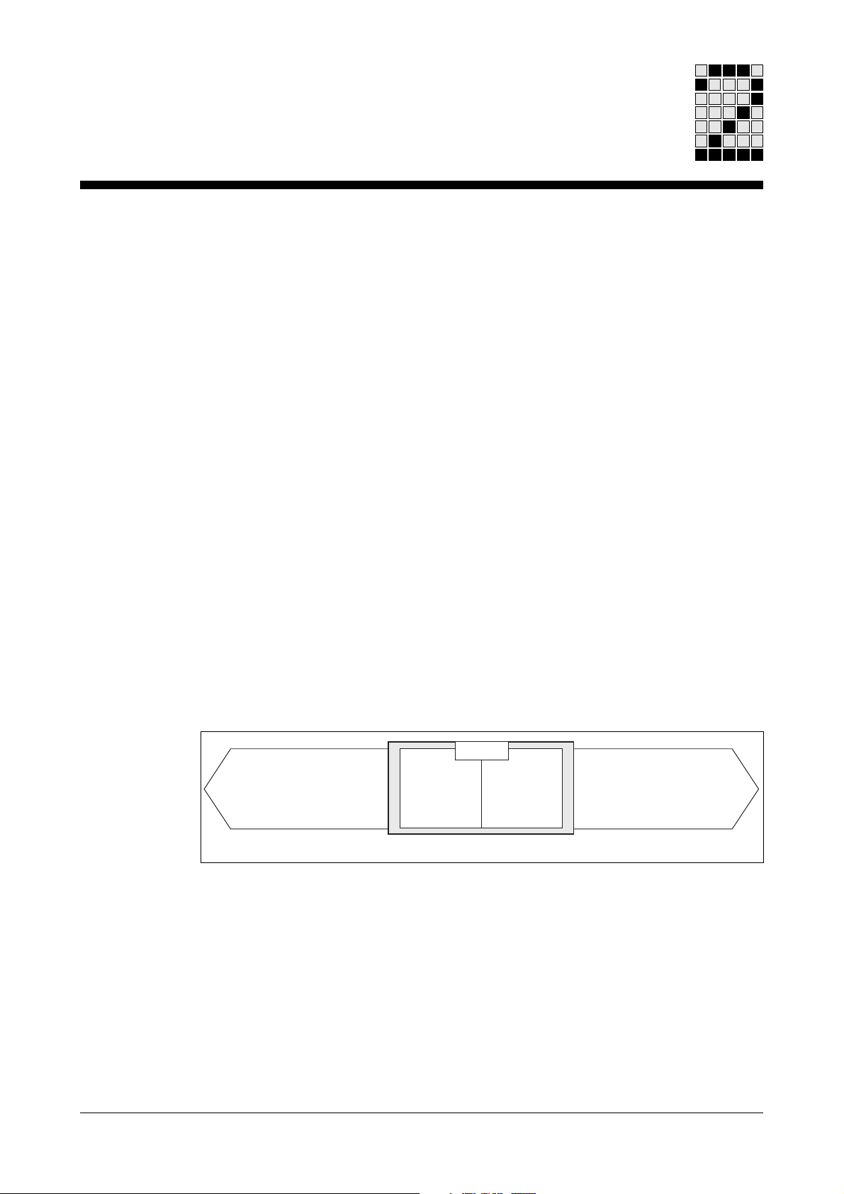
The programmable control systems PSS have been designed for use in
plant and machinery safety circuits. They consist of a failsafe (FS) section
and a standard (ST) section.
Control and monitoring of
Steuerung von
safety-related
sicherheitsgerichteten
tasks
Aufgaben
e.g.: E-STOP circuits etc.
z. B.: NOT-AUS usw.
Fig. 2-1: Structure of the PSS
Fail-safe-
Failsafe
Section
Teil
PSS
Standard-
Standard
Teil
Section
Steuerung und
Control of
Regelung von
non-safety-related
nicht sicherheitsgerichteten
tasks
Aufgaben
e.g.: diagnostics etc.
z. B.: Diagnose usw.
This software package is designed for use in the standard section of a
programmable control system PSS.
PROFIBUS-DP-Slave Operating Manual 2-1
Page 10

Overview
Functions
Range
The PROFIBUS-DP-Slave supports the following functions:
• Internal system diagnostics
• Device-related diagnostics
• Transfer of max. 488 bytes of user data
INFORMATION
In this manual, data transfer is always regarded as viewed from the PSS:
Input data is sent from the Master to the PSS, output data is sent from the
PSS to the Master.
The software package consists of:
• one disk and
• one operating manual: PROFIBUS-DP-Slave Software
The disk contains:
• Standard function blocks SB 230, SB 231, SB 232
• Master data files:
PILZ2500.GSD (German)
PILZ2500.GSE (English)
PILZ2500.GSF (French)
• One sample program
2-2 PROFIBUS-DP-S -Slave Operating Manual
Page 11

Intended Use
This software package is designed to connect a programmable control
system PSS to PROFIBUS-DP. It is essential to use a suitable module or
compact safety system.
This software package is intended for use with the following programmable
control systems PSS:
• PSS DP-S module when using a module rack from the PSS 3000 series.
• PSS1 DP-S module when using a module rack from the PSS 3100
series.
• PSS SB 3006 DP-S programmable safety system as a compact device.
The safety systems are passive subscribers (Slaves) on PROFIBUS-DP.
The meet standard EN 50170 Volume 2, PROFIBUS.
Disregard of the information in this manual and use of the software
package outside the specifications described here will be deemed as
improper application.
INFORMATION
This software package is exclusively for use in non-safety-related
applications. It must be used in the standard section of the PSS.
Conditions for operation:
• The module must be installed in accordance with the PROFIBUS DPSlave Hardware Manual and the relevant “Installation Manual” for the
programmable safety system.
• You must be familiar with and adhere to standard EN 50170 Volume 2,
PROFIBUS.
PROFIBUS-DP-Slave Operating Manual 3-1
Page 12

Intended Use
Standard function block SB 230
SB 230 may be used with the following functions and parameters:
• PROFIBUS-DP connection
• To trigger a slave reset
• To trigger static diagnostics
• Permitted data lengths:
Input data: 0 ... 108 words (set via parameters)
Output data: 0 ... 108 words (set via parameters)
Diagnostic data: 4 ... 35 words (set via parameters)
Configuration data: 1 ... 244 bytes (set via parameters)
Please note that the overall data length may be a max. of 1472 Bytes.
Information on calculating the data length can be found in the section
entitled "Setting data blocks".
INFORMATION
SB 230 must be called up in the user program as part of each cycle.
3-2 PROFIBUS-DP-Slave Operating Manual
Page 13
Setting Parameters
Setting Parameters
Before operating the PSS(1) DP-S and PSS SB 3006 DP-S, a number of
parameters must be established and then entered in a data block. You can
use any free data block or amend the data block supplied (DB 050).
Data block configuration:
Data word Contents
DW 0000
... Input data from the Master to the PSS
DW 0127
DW 0128
... Output data from the PSS to the Master
DW 0255
DW 0256
... Diagnostic data
DW 0383
DW 0384
... Configuration data
DW 0511
DW 0512
... Reserved
DW 0767
DW 0768
... Control and status information
DW 1023
PROFIBUS-DP-Slave Operating Manual 4-1
Page 14

Setting Parameters
Diagnostics
The diagnostics function provides information about the PSS / Slave to the
Master. The standard divides diagnostic information into two areas:
• Internal system diagnostic data
• External diagnostic data
- device-specific diagnostic data
- user-specific diagnostic data
Internal system and device-specific diagnostic data is transferred
automatically. If the PSS(1) DP-S or PSS SB 3006 DP-S receives a
diagnostic message, it will inform the Master that it is present. The Slave
cannot send the diagnostic data until the Master requests it. During
transmission, I/O data traffic (transfer of usable data) is interrupted.
It is also possible to transfer user-specific messages (diagnostic data).
The time of transfer for user-specific messages can be set individually.
The user establishes the event which will trigger the transfer of diagnostic
data.
Application example: a machine's operating status is to be transmitted
constantly (e.g. 10 Bytes). If a certain temperature is exceeded, additional
data will be required (e.g. 40 Bytes). The 10 Bytes for operating status will
be transferred within the usable data; the 40 Bytes of additional data will
be transferred in diagnostics mode. This means that in normal operation,
only small amounts of data are transferred and the communication speed
will be high. In exceptional cases (when the temperature is exceeded),
larger amounts of data must be transferred and the communication speed
will be reduced.
Internal system diagnostics
Standard function block SB 230 prepares data for internal system
diagnostics:
Byte 1 Bit 6: Prm_Fault
Byte 1 Bit 3: Ext_Diag
Byte 1 Bit 1: Station_Not_Ready
4-2 PROFIBUS-DP-Slave Operating Manual
Page 15

Setting Parameters
Byte 2 Bit 1: Stat_Diag
Byte 2 Bit 0: Prm_Req
Byte 3 Bit 7: Ext_Diag_Overflow
Byte 5-6: ID-number 2500H (ID-number assigned through PROFIBUS
User Organisation)
INFORMATION
For details of what the parameters mean, please refer to the PROFIBUS
standard EN 50170 Volume 2.
External diagnostics
On the PSS(1) DP-S and PSS SB 3006 DP-S, external diagnostics are
limited to device-related diagnostics. ID and channel-related diagnostics
are only sensible if more than 61 Bytes of user-specific diagnostic data are
to be transferred. These diagnostic types are not described in this manual.
Please refer to EN 50170 and note also that these applications may not be
possible with all Master-Slave configurations.
Device-related diagnostics
Device-related diagnostics automatically detect whether the PSS is in a
RUN or STOP condition. A maximum of 61 Bytes of memory is available
for additional user-specific messages.
Device-related diagnostics without user-specific messages:
Only 2 data bytes are required for this type of diagnostics: one data byte
for the coding and one for the contents. The two data bytes correspond to
Bytes 7 and 8.
Enter the following values in the data block:
.
.
.
DL DR
DW 0259 Byte 8 Byte 7
...
DW 0812 KF 04
.
.
.
PROFIBUS-DP-Slave Operating Manual 4-3
Page 16

Setting Parameters
Contents of data word DW 0259 DR: Header byte 7:
Bit No. 7 6543210
00000010
Code for Block length in Bytes including
Device-related diagnostics Header byte: 2 Bytes
INFORMATION
In the case of device-related diagnostics without user-specific messages,
DW 0259 DR will always contain 02.
The PSS(1) DP-S or PSS SB 3006 DP-S registers in DW 0259 DL:
Header byte 8:
Bit No. 7 6543210
xxxxxxx 0/1
0: ST section of PSS in RUN mode
Not used 1: ST section of PSS in STOP mode
The PSS(1) DP-S or PSS SB 3006 DP-S uses a hardware signal to detect
whether the PSS standard section is in a RUN or STOP condition.
INFORMATION
This type of diagnostics is only possible if the slave has been fully
initialised by the PSS and has been recognised by the Master.
The length of the diagnostic data must be entered in DW 0812. Diagnostic
data has a length of at least 4 words:
3 words of internal diagnostic data in DW 0256, 0257 and 0258
+ 1 word in DW 0259 (as described).
4-4 PROFIBUS-DP-Slave Operating Manual
Page 17

Setting Parameters
Device-related diagnostics with user-specific messages:
Device-related diagnostics can be extended by a maximum of 61 Bytes
with user-specific messages. These messages are entered in the data
block from DW 0260.
Enter the following values in the data block:
.
. DL DR
.
DW 0259 Byte 8 Byte 7
DW 0260
... User-specific messages
DW 0383
.
.
.
DW 0812 KF Length of diagnostic data
.
.
.
Contents of data word DW 0259 DR: Header byte 7:
MSB LSB
Bit No. 7 6 5 43210
00xxxxxx
Code for Length of user messages:
device-related diagnostics 2 ... 63 relates to 2 ... 63 Bytes
If the length entered in DW 0259 is greater than 2, the user messages will
follow on from DW 0260 (Byte 9). If the length entered is less than 2,
device-specific diagnostics will not be possible.
Contents of data word DW 0259 DL: Byte 8:
In DW 0259 DL the PSS(1) DP-S or PSS SB 3006 DP-S registers whether
the PSS standard section is in a RUN or STOP condition (see page 4-4).
The length of the diagnostic data must be entered in DW 0812. This is
composed of:
3 words of internal diagnostic data (DW 0256+DW 0257+DW 0258)
+ 1 word of device-specific diagnostic data (DW 0259)
+ x words user-specific data.
PROFIBUS-DP-Slave Operating Manual 4-5
Page 18

Setting Parameters
Configuring input and output data
The length of the input and output data plus data consistency are all
established through the configuration. Data consistency can refer to a
single word or to the whole data length. The maximum data length of the
input or output data is 122 words (244 Bytes). The configuration of the
Master, PSS(1) DP-S or PSS SB 3006 DP-S must match (see also
Chapter 6, page 6-4).
INFORMATION
The PSS(1) DP-S or PSS SB 3006 DP-S transfers all data word by word.
As the PSS CPU always accesses the Slave word by word, byte structures
are not supported.
There are two ways of configuring the PSS(1) DP-S or PSS SB 3006
DP-S: either through a simple ID-format which establishes the length,
consistency and direction of communication, or by means of a special ID
which allows for additional data through a separate length byte. The
configuration is undertaken in an “ID-Byte”.
Simple ID-Format
The simple ID-format is suitable for transmissions of up to a maximum of
16 words. With larger transmissions you will either need to use several IDbytes in succession or the special ID-format.
Enter the following parameters in the data block:
• When only output or input data is being transferred, or when input and
output data of the same length is to be transferred simultaneously:
.
.
.
DW 0384
.
.
.
DW 0813 Length of the configuration data in Bytes
• When input and output data of different lengths is to be transferred
simultaneously:
.
.DLDR
.
DW 0384 Input ID-Byte Output ID-Byte
.
.
.
DW 0813 Length of the configuration data in Bytes
DL DR
00 ID-Byte
4-6 PROFIBUS-DP-Slave Operating Manual
Page 19

Setting Parameters
Contents of ID-Byte:
Bit No. 7 6 5 43210
x1xxxxxx
Length of data: 0000 ... 1111
corresponds to 1 ... 16 words
Input / Output
00 = Special ID-format
01 = PSS output data
10 = PSS input data
11 = PSS input and output data
Data structure: 1: Word, 0: Byte
We recommend you set Bit 6 = 1 (Word)
Consistency: 0: for one word, 1: for the whole data length
The length of the configuration data must be entered in bytes in DW 0813.
The length is 1, if only one byte is used, or two if both bytes of data word
DW 0384 are used.
Examples: Consistency always over the whole data length
DW 0384
1 word output 1101 0000
16 words output 1101 1111
1 word input 1110 0000
16 words input 1110 1111
Input and output, 1 word each 1111 0000
Input and output, 12 words each1111 1011
1 word output and 1101 0000
2 words input 1110 0001
D0
B
B
B
B
B
B
B
B
DF
E0
EF
F0
FB
D0
E0
H
H
H
H
H
H
H
H
00 D0
00 DF
00 E0
00 EF
00 F0
00 FB
E0 D0
15 words output and 1101 1110
16 words input 1110 1111
PROFIBUS-DP-Slave Operating Manual 4-7
DE
B
B
EF
H
H
EF DE
Page 20

Setting Parameters
Special ID-Format
The ID-format occupies a maximum of three data words. Enter the
following values in the data block:
• When only output or input data is to be transferred:
.
.DLDR
.
DW 0384 Length-Byte ID-Byte
.
.
.
DW 0813 KF 2 ;Length of the configuration data in Bytes
.
.
.
• When input and output data is to be transferred simultaneously:
.
.DLDR
.
DW 0384 Length-Byte E ID-Byte
.
.
.
DW 0813 KF 3 ;Length of the configuration data in Bytes
.
.
.
• When more than 64 Bytes of input and output data are to be transferred
simultaneously. Data must be transferred consecutively: first the 64
Bytes and then the remaining Bytes:
.
.DLDR
.
DW 0384 Length-Byte E ID-Byte
.
.
.
DW 0813 KF 6 ;Length of the configuration data in Bytes
.
.
.
00 Length-Byte A
ID-Byte Length-Byte A
Length-Byte A Length-Byte E
4-8 PROFIBUS-DP-Slave Operating Manual
Page 21

Setting Parameters
ID-Byte:
Bit No. 7 6 5 43210
xx00xxxx
00 = Reserved
01 = 1 length byte for PSS output data follows
10 = 1 length byte for PSS input data follows
11 = 1 length byte for PSS input data and one length byte for
Length of manufacturer-specific data
ID-code
PSS output data follow
INFORMATION
Manufacturer-specific data is not pre-assigned by Pilz. Users may enter
their own data - please refer to the standard.
If no data is to be entered, enter the value 0 in Bits 0 ... 3 .
Length-Byte:
Bit No. 7 6 5 43210
x1xxxxxx
Length of data: 000000 ... 111111 corresponds to
1 ... 64 words
Data structure: 1: Word, 0: Byte
We recommend you set Bit 6 = 1 (Word)
Consistency: 0: for one word, 1: for the whole data length
INFORMATION
The amount of configuration data must be entered in Bytes in DW 0813.
PROFIBUS-DP-Slave Operating Manual 4-9
Page 22

Setting Parameters
Examples: Consistency always over the whole data length
1 word output 0100 0000
1100 0000
DL DR
40
B
B
C0
H
H
CO 40
16 words output 0100 0000
1100 1111
1 word input 1000 0000
1100 0000
64 words input 1000 0000
1111 1111
Input and o/p, 2 words each 1100 0000
1100 0001
1100 0001
Input and o/p, 16 words each 1100 0000
1100 1111
1100 1111
Input and o/p, 64 words each 1100 0000
1111 1111
1111 1111
40
B
B
B
B
B
B
B
B
B
B
B
B
B
B
B
CF
80
C0
80
FF
C0
C1
C1
C0
CF
CF
C0
FF
FF
H
H
H
H
H
H
H
H
H
H
H
H
H
H
H
CF 40
C0 80
FF 80
C1 C0
00 C1
CF C0
00 CF
FF C0
00 FF
2 words input and 1100 0000
3 words output 1100 0001
1100 0010
16 words input and 1100 0000
4 words output 1100 1111
1100 0011
4-10 PROFIBUS-DP-Slave Operating Manual
C0
B
B
B
B
B
B
C1
C2
C0
CF
C3
H
H
H
H
H
H
C1 C0
00 C2
CF C0
00 C3
Page 23

Setting Parameters
122 words input and 2 words output
1st ID-Byte for input data
Length-Byte for input data (64 words)
2nd ID-Byte for output data
Length-Byte for output data C1 40
3rd ID-Byte for input data
Length-Byte for input data (58 words)
Setting data blocks
1000 0000
1111 1111
0100 0000
1100 0001
1000 0000
1111 1001
80
B
B
B
B
B
B
FF
40
C1
80
F9
H
H
H
H
H
H
FF 80
F9 80
Enter the values in a data block, as shown overleaf. In addition to
diagnostic and configuration data, the following data words must be
written:
• The first 128 data words are reserved for input data and the next 128 for
output data.
• Enter the maximum length of the diagnostic data in data word DW 0783.
This value means that a memory area is reserved for the diagnostic data
during initialisation. The value max_diag_len is stated in bytes and must
be at least equal to the length in words of the diagnostic data in data
word DW 0812.
INFORMATION
DW 0812 should be entered in words and DW 0783 in bytes!
• “F5” should always be entered in data word DW 0795.
• The station address should be entered in data word DW 0800. This
address must be identical to the address set on the front plate.
• In data word DW 0801, enter the transmission sequence for the I/O-data
and the user-specific diagnostic data:
0: (default; Motorola) The PSS sends the left data byte to the
Master first, followed by the right data byte.
1: (Intel) the PSS transmits the right data byte first, followed by the
left data byte.
PROFIBUS-DP-Slave Operating Manual 4-11
Page 24

Setting Parameters
• Enter the length of the input data in data word DW 0810 and the length of
the output data in data word DW 0811.
• Always enter “0” in data words DW 0814 and DW 0815.
Data block configuration:
NOTICE
Only edit data words and output data that are shaded grey.
Data words 256, 257, 512 ... 782, 784 ... 794, 796 ... 799, 802 ... 809 and
816 ... 1023 cannot be amended!
Data word Type Contents
DW 0000...DW 0127 Input data Master --> PSS
DW 0128...DW 0255 Output data PSS --> Master
DW 0256 Reserved for internal diagnostic data
DW 0257 Reserved for internal diagnostic data
DW 0258 KH ID number: 2500 hex
DW 0259 KH Device-specific diagnostic data [Byte]
DW 0260...DW 0383 KH User-specific diagnostic data
DW 0384...DW 0511 KH Configuration data
DW 0512...DW 0782 Reserved
DW 0783 KF max_diag_len [Byte] (>2 x DW 0812)
DW 0784...DW 0794 Reserved
DW 0795 KH Only F5 hex is permitted
DW 0796...DW 0799 Reserved
DW 0800 KF Slave address 0 ... 126
DW 0801 KF Transmission sequence of Bytes 0 or 1
DW 0802...DW 0809 Reserved
DW 0810 KF Length of input data 0 - 122 [Words]
DW 0811 KF Length of output data 0 - 122 [Words]
DW 0812 KF Length of diagnostic data 4 - 35 [Words]
1 Byte Header (DR 0259)
+ 1 Byte Pilz diagnostics (DL 0259)
+ x Byte user diagnostics (DR 0260ff)
Equals coding switch on the module
3 words internal diagnostics (DW 0256 ...
DW 0258)
x words device-specific diagnostics
(= DW 0259 / 2)
4-12 PROFIBUS-DP-Slave Operating Manual
Page 25

Setting Parameters
Data word Type Contents
DW 0813 KF Amount of configuration data 1- 244 [Byte]
DW 0814 KF Only 0 is permitted
DW 0815 KF Only 0 is permitted
DW 0816...DW 1023 Reserved
NOTICE
The data length may be a maximum of 1472 Bytes. The maximum data
length is calculated as follows:
3 x length of the input data
+ 3 x length of the output data
+ 2 x length of the diagnostic data
+ 4 x length of the configuration data
+ 120 Byte
(DW 0384ff)
Examples
Example 1:
12 words input and output: configuration byte FBH ;
Length of configuration data: 1 Byte
Diagnostics: 3 words of internal diagnostic data
1 word of device-related diagnostic data
Data word Contents Description
DW 0000 - DW 0011 ... Input data
DW 0128 - DW 0139 ... Output data
DW 0258 KH 2500 ID-number
DW 0259 KH 0002 Device-related diagnostics
DW 0384 KH 00FB Configuration data
DW 0783 KF 10 max_diag_len [Byte]
DW 0795 KH F5 Pre-assigned
DW 0800 KF 1 Slave address [0-126]
DW 0801 KF 0 Transmission sequence
DW 0810 KF 12 Length of input data in words
DW 0811 KF 12 Length of output data in words
DW 0812 KF 4 Length of diagnostic data in words
DW 0813 KF 1 Amount of configuration data in bytes
DW 0814 KF 0 Pre-assigned
DW 0815 KF 0 Pre-assigned
PROFIBUS-DP-Slave Operating Manual 4-13
Page 26

Setting Parameters
Example 2:
64 words output, special configuration byte: 40, Length byte: FF
Diagnostics: 3 words of internal diagnostic data
1 word of device-related diagnostic data
Data word Contents Description
DW 0128 - DW 0191 ... Output data
DW 0258 KH 2500 ID-Number
DW 0259 KH 0002 Device-related diagnostics
DW 0384 KH FF40 Configuration data
DW 0783 KF 10 max_diag_len [Byte]
DW 0795 KH F5 Pre-assigned
DW 0801 KF 0 Transmission sequence
DW 0800 KF 1 Slave address [0-126]
DW 0810 KF 0 Length of input data in words
DW 0811 KF 64 Length of output data in words
DW 0812 KF 4 Length of diagnostic data in words
DW 0813 KF 2 Amount of configuration data in bytes
DW 0814 KF 0 Pre-assigned
DW 0815 KF 0 Pre-assigned
4-14 PROFIBUS-DP-Slave Operating Manual
Page 27

Setting Parameters
Example 3:
2 words input and 1 word output,
Special configuration byte: C0,
Length byte input: C1
Length byte output: C0
Diagnostics: 3 words of internal diagnostic data
Data word Contents Description
DW 0000 - DW0001 ... Input data
DW 0128 ... Output data
DW 0258 KH 2500 ID-Number
DW 0259 KH 0002 Device-related diagnostics
DW 0384 KH C1C0 Configuration data
DW 0385 KH 00C0
DW 0783 KF 10 max_diag_len [Byte]
DW 0795 KH F5 Pre-assigned
DW 0800 KF 1 Slave address [0-126]
DW 0801 KF 0 Transmission sequence
DW 0810 KF 2 Length of input data in words
DW 0811 KF 1 Length of output data in words
DW 0812 KF 4 Length of diagnostic data in words
DW 0813 KF 3 Amount of configuration data in bytes
DW 0814 KF 0 Pre-assigned
DW 0815 KF 0 Pre-assigned
1 word of device-related diagnostic data
PROFIBUS-DP-Slave Operating Manual 4-15
Page 28

Setting Parameters
Example 4 :
100 words input and output
Configuration byte: C0
Length byte input (64 words): FF
Length byte output (64 words): FF
Configuration byte: C0
Length byte input (36 words): E3
Length byte output (36 words): E3
Diagnostics: 3 words of internal diagnostic data
Data word Contents Description
DW 0000 - DW 0099 ... Input data
DW 0128 - DW 0227 ... Output data
DW 0258 KH 2500 ID-number
DW 0259 KH 0052 Device-related diagnostics
DW 0384 KH FFC0 Configuration data
DW 0385 KH C0FF
DW 0386 KH E3E3
DW 0783 KF 58 max_diag_len [Byte]
DW 0795 KH F5 Pre-assigned
DW 0800 KF 1 Slave address [0-126]
DW 0801 KF 0 Transmission sequence
DW 0810 KF 100 Length of input data in words
DW 0811 KF 100 Length of output data in words
DW 0812 KF 29 Length of diagnostic data in words
DW 0813 KF 6 Amount of configuration data in bytes
DW 0814 KF 0 Pre-assigned
DW 0815 KF 0 Pre-assigned
1 word of device-related diagnostic data
50 bytes of user-specific diagnostic data
4-16 PROFIBUS-DP-Slave Operating Manual
Page 29

Setting Parameters
Example 5:
2 words input and 1 word output
Configuration byte: C0
Length byte input: C1
Length byte output: C0
Diagnostics: 3 words of internal diagnostic data
Data word Contents Description
DW 0000 - DW 0001 ... Input data
DW 0128 ... Output data
DW 0258 KH 2500 ID-number
DW 0259 KH 0004 Device-related diagnostics
DW 0260 KH xxxx User-specific diagnostic data
1 word of device-related diagnostic data
2 bytes of user-specific diagnostic data
DW 0384 KH C1C0 Configuration data
DW 0385 KH 00C0
DW 0783 KF 10 max_diag_len [Byte]
DW 0795 KH F5 Pre-assigned
DW 0800 KF 1 Slave address [0-126]
DW 0801 KF 0 Transmission sequence
DW 0810 KF 2 Length of input data in words
DW 0811 KF 1 Length of output data in words
DW 0812 KF 5 Length of diagnostic data in words
DW 0813 KF 3 Amount of configuration data in bytes
DW 0814 KF 0 Pre-assigned
DW 0815 KF 0 Pre-assigned
PROFIBUS-DP-Slave Operating Manual 4-17
Page 30

Setting Parameters
Notes
4-18 PROFIBUS-DP-Slave Operating Manual
Page 31

Commissioning
Configuration
Before commissioning, the following values need to be established:
• The number of inputs and outputs in words
• The amount of diagnostic data in words
• Station address (see PROFIBUS-DP-Slave Hardware Manual or PSS SB
3006 DP-S Shortform).
The Master can be configured using the configuration data and the data
from the unit's master data file.
Commissioning Sequence
Requirement
The module must have been installed in accordance with the instructions
provided in the PROFIBUS-DP-Slave Hardware Manual or PSS SB 3006
DP-S Shortform. Master and Slave must be ready for operation.
• Create a cold-start organisation block, OB 020, and state the necessary
parameters in a data block; enter the slave module under hardware
registry in DB 004; an example for OB 020 can be found in the Appendix.
• Establish the parameters for standard function block SB 230 (see
Chapter 6 for further details).
• SB 230 must be called up in each PSS cycle.
• Transfer the following blocks to the PSS:
- OB 001 and OB 020
- SB 230, SB 231 and SB 232
- DB 4, DB 5 and the data block containing the parameters
- any additional blocks required by the user.
• After configuration, output parameter
230 can no longer register an error. It should display:
Any other value indicates an error. For further information please refer to
Chapter 6, “Standard Function Blocks”.
ERR
on standard function block SB
ERR
= KH 2000.
PROFIBUS-DP-Slave Operating Manual 5-1
Page 32

Commissioning
Notes
5-2 PROFIBUS-DP-Slave Operating Manual
Page 33

Standard Function Blocks
SB 230
Function
• Communication between the PSS and PROFIBUS-DP-Slave
• Trigger a Slave reset
• Trigger static diagnostics
Block Header
SB230
DP-SLAVE
W- BASE ERR -W
B- DB
B- MODE
W: Word, B: Byte
Parameters
• Input parameters
- BASE: Module's start address (Offset)
The module occupies 1024 words after the start address.
These words may not be accessed.
- MODE: = 01: Static diagnostics
= 02: Reset:
All other values: Data exchange (Data_exchange):
- DB: Data block
• Output parameters
ERR: Error message (see table below)
ERR (hex) Key Cause/Remedy
0001 DP_SL_ERR_DPS2_LENGTH Total length calculated for diagnostic,
parameter, input and output data is too
high; reduce the data length!
0002 DP_SL_ERR_DPS2_INIT Hardware initialisation error;
Change PSS(1) DP-S module or
PSS SB 3006 DP-S
PROFIBUS-DP-Slave Operating Manual 6-1
Page 34

Standard Function Blocks
ERR (hex) Key Cause/Remedy
0003 DP_SL_ERR_SSA_IND Master attempting to change slave
address; reconfigure Master
0004 DP_SL_ERR_DIAG_LEN Diagnostic data length is incorrect;
Change data length
0005 DP_SL_ERR_CFG_LEN Configuration data length is incorrect;
Change length
0006 DP_SL_ERR_PRM_LEN Parameter data length is incorrect;
Change length
0007 DP_SL_ERR_IO_LEN Data length is incorrect (inputs or outputs);
Change length
0008 DP_SL_ERR_DP_WD_TIMEOUT Master monitoring has elapsed;
0009 DP_SL_ERR_WRONG_ADRESS Invalid station address has been set;
Set a valid address (0 - 126) on the switch
and in the data block
000A DP_SL_ERR_IDENT_NR_P Incorrect ID-number in data block;
Correct ID-number: 2500 hex.
000B DP_SL_ERR_WRONG_DB_NR Invalid DB number; select a valid DB
000C DP_SL_ERR_IO_NULL_PTR Input and output data length equal zero;
check the configuration data
1000 DP_SL_ERR_SLAVE_NOT_ Slave does not respond or is busy;
READY Reset the module
1001 DP_SL_ERR_WRONG_SLAVE_ Undefined slave condition; reset or
STATE restart module
1002 DP_SL_ERR_DIAG_DATA_ Access to DPR denied; reset or restart
AREA_NOT_READY module
1003 DP_SL_ERR_CFG_DATA_ Access to DPR denied; reset or restart
AREA_NOT_READY module
00FA DP_SL_ERR_DPRAM_TIMEOUT PSS not enabling the DPR or DPR
is defective; reset or restart module
00FB DP_SL_ERR_SET_PRM Parameter data on Master and Slave do
not match; check the configuration data
00FC DP_SL_ERR_MASTER_NOT_ Master not available, bus interrupted
READY when starting the slave
6-2 PROFIBUS-DP-Slave Operating Manual
Page 35

Standard Function Blocks
ERR (hex) Key Cause/Remedy
00FD DP_SL_ERR_CHK_CFG Configuration data on Master and Slave
do not match; check the configuration
data on the Slave and the Master. See
“Copying the Slave configuration from the
Master configuration”, page 6-4
00FE DP_SL_ERR_BUS_FAULT No communication between Master and
Slave, e.g. incorrect slave ID-number
on the Master, Bus interrupted during
data exchange, Master switched off;
Establish cause and rectify
00FF DP_SL_ERR_FATAL Hardware error; change PSS(1) DP-S
module or PSS SB 3006 DP-S
2000 DP_SL_NO_ERROR No error detected
2001 DP_SL_ERR_SLAVE_NOT_ Slave does not respond or is busy;
READY Reset the module
2002 DP_SL_ERR_DIAG_DATA_ PSS not enabling the DPR or DPR
AREA_NOT_READY is defective; Change PSS(1) DP-S module
or PSS 3006 DP-S.
2003 DP_SL_ERR_ IN_DATA_ PSS not enabling the DPR or DPR
AREA_NOT_READY is defective; Change PSS(1) DP-S module
or PSS 3006 DP-S.
2004 DP_SL_ERR_ OUT_DATA_ PSS not enabling the DPR or DPR
AREA_NOT_READY is defective; Change PSS(1) DP-S module
or PSS 3006 DP-S.
2005 DP_SL_RESET_MODE A reset has been triggered.
2006 DP_SL_ERR_ILLEGAL_MODE Invalid mode has been set
2007 DP_SL_ERR_ILLEGAL_ Undefined slave condition; reset or restart
SLAVE_STATE the module.
INFORMATION
Standard function blocks SB 231 and SB 232 must also be transmitted to
the controller in addition to SB 230. However, parameters do not need to
be set for them, nor do they need to be called up.
NOTICE
The flag range MW 059.00 ... MW 063.16 is reserved for temporary flags.
This range may not be used for global parameters, nor for SB input or
output parameters, otherwise the flags used in the SB will be overwritten.
PROFIBUS-DP-Slave Operating Manual 6-3
Page 36

Standard Function Blocks
Copying the Slave configuration from the Master configuration
The configuration data for the Slave is located in the data block from
DW 0384 (see Chapter 4, “Setting Parameters”), while the configuration
data for the Master is entered from DW 0830. The length of the
configuration data is entered in DR of DW 0830. This is followed by the
data.
Compare the values on the Master and the Slave and ensure they match.
The following table provides information on the entries.
NOTICE
The addresses of the data block in which the Master writes the
configuration data can be found in the “DP Master” column. The data block
addresses for the Slave configuration data can be found in the “PSS (DP
Slave)” column. The Slave's configuration data must be checked and, if
necessary, adjusted to that of the DP Master.
Configuration
Amount of configuration data
[Bytes]
1st configuration data byte
2nd configuration data byte
3rd configuration data byte
4th configuration data byte
5th configuration data byte
6th configuration data byte
...
Sum total of input data
[Words]
Sum total of output data
[Words]
DP
Master
DR 0830
DL 0830
DR 0831
DL 0831
DR 0832
DL 0832
DR 0833
...
PSS
(DP Slave)
DW 0813
DR 0384
DL 0384
DR 0385
DL 0385
DR 0386
DL 0386
...
DW 0810
DW 0811
Contents
Type
KH
KH
KH
KH
KH
KH
KH
...
KF
KF
Value
06
C0
CD
CF
C0
41
40
...
16
17
Example
Input
data
[Words]
14
2
...
16
Output
data
[Words]
16
1
...
17
6-4 PROFIBUS-DP-Slave Operating Manual
Page 37

Appendix
Example
Data block DB 050 is selected for setting the parameters. The data block
is configured in OB 020. The configuration corresponds to Example 5 in
Chapter 4. SB 230 is called up in OB 001.
OB 020 Cold start ST
:A DB 004 ;Registered hardware on standard section
:L KH B220 ;Enter the code of the module (B220)
:T DW 0027 ;on slot 7
:
:A DB 005 ;Start address for Slave module
:L KH 0000 ;Start address (Offset) is 0
:T DW 0007 ;Slave module on slot 7
:
:L KH 0000 ;Reset the used flag
:T MB 000.00 ;in OB 001
:T MW 030.00 ;
:T MW 010.00 ;
:
:A DB 050 ;Data block for setting the parameters
;(input parameter “DB” from SB 230)
:L KH 2500 ;ID-Number
:T DW 0258 ;
:
:L KH 0004 ;Length of the diagnostic data [Bytes]
:T DW 0259 ;
:
:L KH C1C0 ;Configuration data
:T DW 0384 ;
:L KH 00C0 ;
:T DW 0385 ;
:L KF 0010 ;Reserved
:T DW 0783 ;
:L KH 00F5 ;Reserved
:T DW 0795 ;
:
:L KF 0001 ;Station address [0-126]
:T DW 0800 ;
PROFIBUS-DP-Slave Operating Manual 7-1
Page 38

Appendix
:L KF 0000 ;Reserved
:T DW 0801 ;
:L KF 000002 ;Length of input data [Words]
:T DW 0810 ;
:L KF 000001 ;Length of output data [Words]
:T DW 0811 :
:L KF 000005 ;Length of diagnostic data [Words]
:T DW 0812 ;
:L KF 000003 ;Amount of configuration data [Bytes]
:T DW 0813 ;
:
:L KF 000000 ;Reserved
:T DW 0814 ;
:L KF 000000 ;Reserved
:T DW 0815
7-2 PROFIBUS-DP-Slave Operating Manual
Page 39

Appendix
OB 001
Comment: Segment 00
************************************************************************************
* Sample program *********************************************************
************************************************************************************
**
* 2 Words input data *
* 1 Word output data *
* 1 Word diagnostic data *
**
* Key to inputs / outputs: *
* E 02.00 triggers a module reset *
* E 02.01 Slave goes to a static diagnostic condition *
**
* Cyclical data transfer : *
* PSS -> Master(output data): *
* AW 0.0 -> DW 0128 -> Master *
**
* PSS <- Master(input data): *
* EW 1.0 <- DW 0000 <- Master *
* EW 1.16 <- DW 0001 <- Master *
**
* If an error occurs in the FS Section of the PSS (M113.01 = 1), *
* the slave module will go to a static diagnostic condition. *
* In the example, the value KH FFFF is sent to the Master as diagnostic *
* data. *
*************************************************************************************
:L E 02.00
:SPB = reset
:L E 02.01
:SPB = stat.diag
:L KF 000000
:T MB 000.00
:SPA = start
reset: Segment 01
:L KB 002
:T MB 000.00
:SPA = start
PROFIBUS-DP-Slave Operating Manual 7-3
Page 40

Appendix
stat.diag: Segment 02
start: Segment 03
no_err: Segment 05
:L KB 001
:T MB 000.00
:A DB 050
:L DW 0000
:T EW 01.00
:L DW 0001
:T EW 01.16
:
:L AW 00.00
:T DW 0128
:
:LN M 113.01 .FS_no_ERR/ERR status FS, 0 = no error, 1 = err
:SPB = no_err
:L KH FFFF
:T DW 0260
:L KH 0000
:L KB 001
:T MB 000.00
:
**********************************************************************************
* Input parameters: *
* -Base: Module's XW-Offset *
* -Mode: KB001 -stat.Diagnostics *
* KB002 -Module reset *
* KB000 -Data-Exchange *
* -DB: Data block KB 011-KB 127 or -KB 255 *
(from operating system version 9) *
**
* Output parameters: *
* -Fehl: Error evaluation *
* KH 2000: No errors *
* see chapter entitled “Standard function blocks” *
**********************************************************************************
7-4 PROFIBUS-DP-Slave Operating Manual
Page 41

Appendix
Display ERR : Segment 06
:
:CAL SB 230
SB230
DP-Slave
KF 00000 -W- BASE
MB 000.00 -B- MODE ERR -W - MW 030.00
KB 050 -B- DB
**********************************************************************************
*FB 100 ************************************************************************
**********************************************************************************
* Input parameters: *
* -Disp: 1 = Errors output to the display *
* 0 = Errors not output to the display *
**
* -ERR: Flag word which is output to the display *
**
* M 010.00 internal flag *
**
**********************************************************************************
:
: CAL FB 100
FB100
Display
E 02.03 -X- DISP
MW 030.00 -W- ERR
end: Segment xx
:BE
PROFIBUS-DP-Slave Operating Manual 7-5
Page 42

Appendix
Changes in the documentation
Changes from Version II to Version III
Master data file was amended.
Changes from Version III to Version IV
The manual is also now valid for the PSS SB 3006 DP-S. Editorially the
manual has been completely revised. The division of chapters has been
amended.
The master data file has been removed from the manual completely (Appendix).
Old New Change
page page
5-2 6-2 Error 00FD: Note added
5-3 6-3 Section: “Copying the Slave configuration from the
Master configuration”
Changes from Version IV to Version V
Old New Change
page page
- 6-2 New: ERR 000C, 00FB, 00FC
- 6-3 New: ERR 2006
Changes in Version 19 419-06
Old New Change
page page
3-2 3-2 Section "Standard function block SB 230" was amended,
note added
4-13 4-13 Section "NOTICE" was amended
7-6 PROFIBUS-DP-Slave Operating Manual
Page 43

...
In many countries we are
represented by our subsidiaries
and sales partners.
Please refer to our Homepage
for further details or contact our
headquarters.
Pilz GmbH & Co. KG
Sichere Automation
Felix-Wankel-Straße 2
73760 Ostfildern, Germany
Telephone: +49 711 3409-0
Telefax: +49 711 3409-133
E-Mail: pilz.gmbh@pilz.de
www
www.pilz.com
Technical support
+49 711 3409-444
19 419-06, 2007-04 Printed in Germany
 Loading...