

Electronic Monitoring Relays
True power monitoring
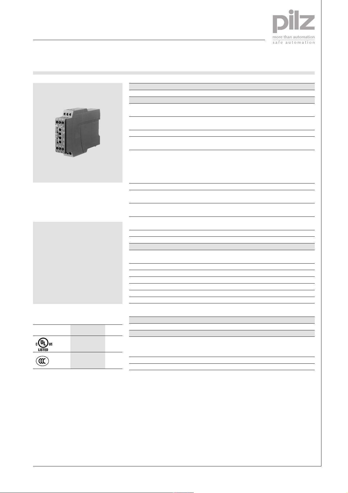
S1WP
Technical details S1WP
Electrical data
Supply voltage DC: 24 V
Tolerance DC: 85 ... 125 %
Frequency range 30 ... 400 Hz
Power consumption DC: 2 W at UB 24 V
Switching capability to
EN 60947-4-1, 10/91 AC 1: 240 V/0.1 ... 5 A/1200 VA
EN 60947-5-1, 10/91 AC15: 230 V/0.1 ... 1.8 A
Output contacts 1 auxiliary contact (C/O)
True power monitor for single and
3-phase networks used to measure
and monitor therated power and true
power on electrical machines
Features
● 9 different measuring ranges
● Large voltage measuring range
● Analogue output can be
switched for current and voltage
● Relay output for signalling
underload or overload
● Suitable for use with frequencycontrolled motors
● Suitable for current transformers
Approvals
S1WP
●
●
Contact material AgCdO, 3 µm gold plating for
Contact fuse protection 6 A quick or 4 A slow
to EN 60947-5-1, 10/91
Analogue measuring output Voltage: 0 ... ±10 V
Analogue reaction time 60 ms
Linearity/switching accuracy < ±2 %
Measuring circuit
Measuring voltage 3AC/1AC/DC: 0 ... 120, 0 ... 240,
Frequency range 0 ... 1000 Hz
Adjustable measuring range limits See table
Max. measuring current 22 A with 100 % continuous duty
Max. overload 45 A/max. 3 s
Reaction time for monitoring UL: 0.1 ... 20 s (adjustable)
Start-up suppression time 0.1 ... 30 s (adjustable)
Requirements for current transformer I = 1 A: 1,5 ... 7.5 VA, Class 3
Environmental data
Ambient temperature 0 ... +55 °C
Mechanical data
Max. cross section of external conductor 1 x 4 mm² or 2 x 1.5 mm
Dimensions (H x W x D) 87 x 22.5 x 122 mm
Weight DC: 130 g, AC: 150 g
AC/DC: 230 V
AC/DC: 25 ... 115 %
AC: 5 VA at UB 230 V
DC1: 24 V/0.1 ... 5 A/120 W
DC13: 24 V/0.1 ... 1.5 A
low-load range 1-50 V/1-100 mA
Current: +4 ... + 20 mA
0 ... 415, 0 ... 550 V
4
I = 5 A: 2,5 ... 15 VA, Class 3
2
Single-core or multi-core
with crimp connector
Description
The true power monitor is enclosed
in an S-95 22.5 mm slimline housing.
There are 4 voltage measuring
ranges. For each measuring range
there are 4 versions available,
determined by measuring current
and control voltage.
Pilz GmbH & Co. KG, Sichere Automation, Felix-Wankel-Straße 2, 73760 Ostfildern, Germany
Telephone: +49 711 3409-0, Telefax: +49 711 3409-133, E-Mail: pilz.gmbh@pilz.de
Features:
● Relay output:
● Versions for 9 A and 18 A
● Fast analogue reaction time
● Adjustable switching threshold for
(Continued on next page)
1 auxiliary contact (C/O)
current measuring ranges
underload or overload from 5 to
100 % of the measuring range
limit
NSG-D-2-257-2005-04
Electronic Monitoring Relays
True power monitoring
S1WP
● Switching hysteresis of 15 %
● Adjustable monitoring reaction
time
● Adjustable start-up suppression
time
● LEDs for supply voltage and
switching status of underload
and overload auxiliary contacts
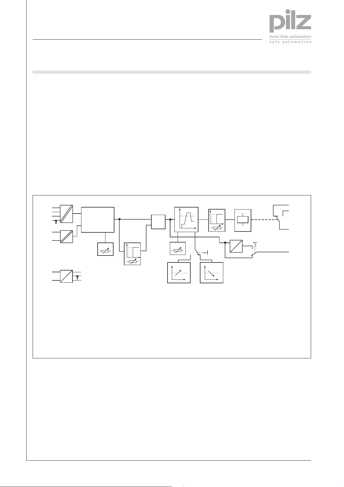
The S1WP monitors the set upper
and lower true power threshold
levels in a single or 3-phase network.
It converts the true power or rated
power on a motor or generator into
an analogue signal output, which is
Block diagram
L1
U
L2
L3
N
K1
U
M
p = RANGE * U
*
I
M
L1
I
M
* cos j
RANGE
M
proportional to true power. The
status of threshold monitoring,
together with the analogue signal
output, is indicated by a relay output.
The S1WP operates in normally
energised mode, which means in its
initial state the contact 11-14 is
closed and 11-12 is open. If normally
de-energised mode is required, the
function of the upper and lower
threshold is inverted.
If the measured true power exceeds
the switching threshold when set to
overload (UL), the auxiliary contact
P
&
t
s
t
delay
LEVEL
S1
switches position and the LED “FLT”
LED is lit. If the measured true power
falls below the switching threshold
when set to underload (LL), the
auxiliary contact switches position
and the LED “FLT” LED is lit.
To avoid spurious output signals
during the start-up phase, measurement is suppressed.
Start-up suppression time ts can be
set. Transient load fluctuations which
exceed the switching threshold can
be suppressed and the reaction time
tr can be set.
tr
delay
U
S2
I
Instantaneous value
12
14
11
U/I
4
A1
U
B
A2
+
0
-
UMMeasuring voltage
I
Measuring current
M
UBSupply voltage
cos ϕPower factor
FLT
UL LL
RANGE Measuring range
t
Start-up suppression time
s
t
Reaction time
r
FLT
LEVEL Switching threshold
UL Overload threshold
LL Underload threshold
Pilz GmbH & Co. KG, Sichere Automation, Felix-Wankel-Straße 2, 73760 Ostfildern, Germany
Telephone: +49 711 3409-0, Telefax: +49 711 3409-133, E-Mail: pilz.gmbh@pilz.de
NSG-D-2-257-2005-04

Electronic Monitoring Relays
True power monitoring
S1WP
Pulse diagram
U/I, P
100 %
LEVEL UL
RANGE
LEVEL LL
Threshold status UL
Threshold status LL
5 %
FLT
FLT
P
U/I
t
s
t
r
t
r
t
r
Hysteresis
Hysteresis
t
t
t
Generator
-P
max
10 V
20 mA
U/I
4 mA
0 V
Motor
U
-10 V
P
max
W
P
P Actual true power
U/I Analogue output signal,
voltage or current
Adjustable measuring range limits P
if used in three-phase network
Meas. range [V]
1 AC/DC
RANGE
T 1 2 3 4 5 6 7 8 9 Version
3 AC kW IM [A] UM [V]
0,208 0,415 0,623 0,83 1,04 1,25 1,45 1,66 1,87 9
0 ... 70 0 ... 120
0,415 0,83 1,25 1,66 2,08 2,5 2,91 3,32 3,74 18
0,415 0,83 1,25 1,66 2,08 2,5 2,91 3,32 3,74 9
0 ... 140 0 ... 240
0,83 1,66 2,5 3,32 4,15 4,5 5,8 6,65 7,5 18
0,72 1,44 2,15 2,88 3,6 4,3 5,03 5,75 6,5 9
0 ... 240 0 ... 415
1,44 2,87 4,3 5,75 7,19 8,6 10,0 11,5 13,0 18
0,95 1,9 2,85 3,8 4,76 5,7 6,7 7,6 8,6 9
0 ... 320 0 ... 550
TEST (reserved function)
1,9 3,8 5,7 7,6 9,5 11,4 13,34 15,24 17,15 18
The variable UM refers to the phaseto-phase voltage in the three-phase
network (3AC).
With single-phase networks (1 AC),
the voltage measuring range drops
to
P [kW]
4
120
240
415
550
U
M (3AC)
=
U
M (1 AC)
Pilz GmbH & Co. KG, Sichere Automation, Felix-Wankel-Straße 2, 73760 Ostfildern, Germany
Telephone: +49 711 3409-0, Telefax: +49 711 3409-133, E-Mail: pilz.gmbh@pilz.de
√ 3
NSG-D-2-257-2005-04

Electronic Monitoring Relays
True power monitoring
S1WP
Connection examples
● Example 1
Monitoring a three-phase AC motor, IN < 9 A/18 A
L1
L2
L3
N
U
B
0 V
F1
U
N
K1
L1
S1WP
U
U/IA1
: 24 V DC
B
L1
U
A2
F2
4
12 14
11 L2 L3
PE
● Example 2
Monitoring a three-phase AC motor; I
L1
L2
L3
N
L1
U
N
U/IA1
S1WP
U
: 230 V AC
B
12 14
11 L2 L3
N
> 9 A/18 A
N
K1
L1
U
A2
N
IN £ 9 A/18 A
1
K1
UVW
M1
M3~
F1
k K
T1
l L
1
K1
Max. cable cross section 4 mm²
UVW
M1
IN > 9 A/18 A
PE
M3~
Pilz GmbH & Co. KG, Sichere Automation, Felix-Wankel-Straße 2, 73760 Ostfildern, Germany
Telephone: +49 711 3409-0, Telefax: +49 711 3409-133, E-Mail: pilz.gmbh@pilz.de
NSG-D-2-257-2005-04

Electronic Monitoring Relays
True power monitoring
S1WP
● Example 3
Monitoring a single-phase motor, IN < 9 A/18 A
L1
N
U
B
0 V
F1
F2
U
N
K1
L1
S1WP
UB: 24 V DC
12 14
11 L2 L3
L1
U
A2
U/IA1
N
K1 H2
PE
● Example 4
Monitoring a single-phase motor; IN > 9 A/18 A
L1
N
K1
L1
12 14
K1 H2
U
U
N
U/IA1
S1WP
UB: 230 V AC
11 L2 L3
L1
A2
N
1
£ 9 A/18 A
I
N
K1
U1 U2
M1
M 1~
4
F1
k K
T1
l L
K1
Max. cable cross section 4 mm²
PE
> 9 A/18 A
I
N
M1
U1 U2
M 1~
Pilz GmbH & Co. KG, Sichere Automation, Felix-Wankel-Straße 2, 73760 Ostfildern, Germany
Telephone: +49 711 3409-0, Telefax: +49 711 3409-133, E-Mail: pilz.gmbh@pilz.de
NSG-D-2-257-2005-04

Electronic Monitoring Relays
True power monitoring
S1WP
General technical details
Unless stated otherwise in the technical details for the specific unit.
Electrical data
Frequency range AC 50 ... 60 Hz
Residual ripple DC 160 %
Contact material AgCdO
Continuous duty 100 %
Environmental data
EMC EN 50081-1, 01/92; EN 50082-2, 03/95
Vibration in accordance with Frequency: 10 ... 55 Hz,
EN 60068-2-6, 04/95 Amplitude: 0.35 mm
Climatic suitability IEC 60068-2-3, 1969
Airgap creepage DIN VDE 0110-1, 04/97
Ambient temperature -10 ... +55 °C
Storage temperature -40 ... +85 °C
Mechanical data
Torque setting for connection terminals 0.6 Nm (screws)
Mounting position Any
Housing material Thermoplastic Noryl SE 100
Protection types Mounting: IP 54
Housing: IP 40
Terminals: IP 20
4
Order references key
IMMeasuring current
UBControl voltage
UMMeasuring voltage
Order references
Type I
S1WP 9 A 24 V DC 0 ... 120 V AC/DC 890 000
S1WP 9 A 24 V DC 0 ... 240 V AC/DC 890 010
S1WP 9 A 24 V DC 0 ... 415 V AC/DC 890 020
S1WP 9 A 24 V DC 0 ... 550 V AC/DC 890 030
S1WP 9 A 230 V AC/DC 0 ... 120 V AC/DC 890 040
S1WP 9 A 230 V AC/DC 0 ... 240 V AC/DC 890 050
S1WP 9 A 230 V AC/DC 0 ... 415 V AC/DC 890 060
S1WP 9 A 230 V AC/DC 0 ... 550 V AC/DC 890 070
S1WP 18 A 24 V DC 0 ... 120 V AC/DC 890 100
S1WP 18 A 24 V DC 0 ... 240 V AC/DC 890 110
S1WP 18 A 24 V DC 0 ... 415 V AC/DC 890 120
S1WP 18 A 24 V DC 0 ... 550 V AC/DC 890 130
S1WP 18 A 230 V AC/DC 0 ... 120 V AC/DC 890 140
S1WP 18 A 230 V AC/DC 0 ... 240 V AC/DC 890 150
S1WP 18 A 230 V AC/DC 0 ... 415 V AC/DC 890 160
S1WP 18 A 230 V AC/DC 0 ... 550 V AC/DC 890 170
M
U
B
U
M
Order No.
Pilz GmbH & Co. KG, Sichere Automation, Felix-Wankel-Straße 2, 73760 Ostfildern, Germany
Telephone: +49 711 3409-0, Telefax: +49 711 3409-133, E-Mail: pilz.gmbh@pilz.de
NSG-D-2-257-2005-04
 Loading...