

Page 1

20 120-01
S1SW P
4
D Betriebsanleitung
4
GB Operating instructions
4
F Manuel d'utilisation
Sicherheitsbestimmungen
• Das Gerät darf nur von einer Elektrofachkraft oder unterwiesenen Personen
installiert und in Betrieb genommen
werden, die mit dieser Betriebsanleitung
und den geltenden Vorschriften über
Arbeitssicherheit und Unfallverhütung
vertraut sind. Beachten Sie die VDEsowie die örtlichen Vorschriften, insbesondere hinsichtlich der Schutzmaßnahmen.
• Halten Sie beim Transport, der Lagerung
und im Betrieb die Bedingungen ein, wie
sie unter den technischen Daten angegeben sind.
• Entsorgen Sie das Gerät nach Ablauf
seiner Lebensdauer sachgerecht.
• Durch Öffnen des Gehäuses oder
eigenmächtige Umbauten erlischt die
Gewährleistung.
• Bauen Sie das Gerät in einen Schaltschrank mit der Schutzart IP54 ein.
• Sorgen Sie bei allen Ausgangskontakten
bei kapazitiven und induktiven Lasten für
eine ausreichende Schutzbeschaltung.
• Diese Bedienungsanleitung dient der
Instruktion. Bewahren Sie sie für künftige
Verwendung auf.
Safety regulations
• Electrical connections should be made by
those who are qualified electrical
engineers or have received sufficient
training and are familiar with the
information in these operating instructions
and the relevant regulations concerning
health and safety at work. Ensure VDE
and local regulations are met, especially
those relating to safety.
• Transport, storage and operating
conditions should conform to the standards
stated under Technical Details.
• The system must be disposed of properly
when it reaches the end of its service life.
• The guarantee is rendered invalid if the
housing is opened or unauthorised
modifications carried out.
• The device should be installed in a control
cabinet with protection type IP54.
• Sufficient fuse protection must be provided
on all output contacts with capacitive and
inductive loads.
• These operating instructions are intended
for instruction and should be retained for
future reference.
Conseils préliminaires
• L’installation et la mise en œuvre de
l’appareil doivent être effectuées par un
électricien ou une personne spécialisée en
installations électriques, en tenant compte
du manuel d’utilisation et des prescriptions
en vigueur au sujet de la sécurité du travail
et de la protection contre les accidents.
Veuillez respecter les règlements VDE
ainsi que les règlements locaux,
notamment en ce qui concerne les
mesures de protection.
• Respecter les exigences des normes
specifiées lors du transport,
du stockage et de l’utilisation de l’appareil
(voir Caractéristiques techniques).
• A la fin de sa durée de service, éliminez
l’appareil conformément aux prescriptions.
• L’ouverture du boîtier ou des modifications non autorisées annulent automatiquement la clause de garantie.
• Installez l’appareil dans une armoire
électrique de classe de protection IP54.
• Assurez-vous du pouvoir de coupure des
contacts de sortie en cas de charges
inductives ou capacitives.
• Le manuel d’utilisation sert à l’instruction.
Veuillez conserver ce manuel pour une
utilisation ultérieure.
Bestimmungsgemäße Verwendung
Der Stillstandswächter S1SW P dient als
Einrichtung zur Stillstandsüberwachung von
Motoren. Das S1SW P ist bestimmt für den
Einsatz in Stillstandsüberwachungen an
Anlagen mit gefährlichen Maschinenteilen
oder Werkzeugen.
Gerätebeschreibung
Der Stillstandswächter ist in einem S-99Gehäuse untergebracht.
Merkmale:
• Relaisausgänge :
2 Hilfskontakte (U)
• Potentiometer „ta“ zum Einstellen der
Auslaufüberwachungszeit
• Potentiometer „Level in %“ zum Einstellen
der Ansprechempfindlichkeit U
(Stillstandsschwelle)
• LED-Anzeige „PWR/FLT“ für Betrieb/
Störung
• LED-Anzeige „STOP“ für Stillstand
• Schiebeschalter „x1/x2“ zur Messbereichsverdoppelung
Der Stillstandswächter S1SW P arbeitet nach
dem Arbeitsstromprinzip, d. h. das Gerät ist
für Sicherheitsanwendungen nur mit
Einschränkung geeignet. Für eine
Sicherheitsschaltung gemäß VDE 0113
empfehlen wir die Sicherheitsschaltgeräte
PSWZ oder PDWZ.
an
Intended use
The S1SW P is used for monitoring standstill
of motors. The S1SW P is intended for use
as a standstill monitor in plants with
dangerous machine parts or tools.
Unit description
The standstill monitor is enclosed in an S-99
housing.
Features:
• Relay outputs:
2 auxiliary contacts (C/O)
• Potentiometer „ta“ to set the rundown
monitoring time
• Potentiometer „Level in %“ to set the
response sensitivity (standstill threshold)
• LED for operation/fault, „PWR/FLT“
• LED for standstill, „STOP“
• Slide switch „x1/x2“ for doubling the
measuring range
The S1SW P operates to normally deenergised mode, i.e. the device has limited
use in process control and safety
applications. We would recommend using the
PSWZ or the PDWZ in safety circuits in
accordance with VDE 0113.
Utilisation conforme
Le contrôleur d’arrêt S1SW P permet de
détecter l’arrêt d’un moteur. Le S1SW P est
conçu pour une utilisation en détecteur
d’arrêt sur des installations avec des parties
de machine ou des outils dangereux.
Description de l’appareil
Le contrôleur d’arrêt est intégré dans un
boîtier S-97.
Particularités :
• Sorties de relais :
2 contacts d’information (OF)
• Potentiomètre « ta » pour régler la durée
de contrôle du temps d’arrêt
• Potentiomètre « Level in % » pour régler
sensibilité d’enclenchement (seuil d’arrêt)
• LED de visualisation du fonctionnement /
des pannes, « PWR/FLT »
• LED de visualisation d’arrêt, « STOP »
• Sélecteur « x1/x2 » pour le doublement de
la plage de mesure
Le contrôleur d’arrêt S1SW P fonctionne par
excitation du relais de sortie; son utilisation
pour des applications de sécurité n’est
possible que sous certaines conditions.
Pour des applications de sécurité selon
VDE 0113, nous recommandons les relais de
sécurité PSWZ ou PDWZ.
la
- 1 -
Page 2
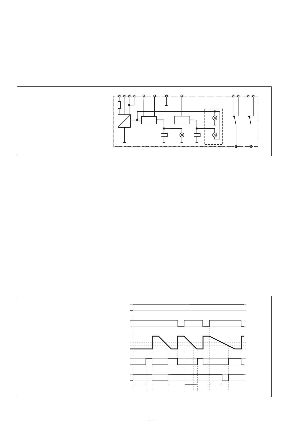
Funktionsbeschreibung
Das Gerät erfasst die in der Motorwicklung
induzierte Spannung UM, die beim Auslaufen
der Motorwelle entsteht. Wenn die Spannung
den eingestellten Ansprechwert Uan unterschreitet, meldet das S1SW P Stillstand.
Nach dem Einschalten der Versorgungsspannung UB und bei Motorstillstand (UM <
Uan) ziehen die Ausgangsrelais K1 und K2
an. Nach Anlauf des Motors fällt K1 ab (UM >
Uab). Der weitere Ablauf ist abhängig von der
verwendeten Betriebsart.
Function description
The device measures the regenerated
voltage UM induced from the motor during the
rundown period. If voltage falls below the set
response value Uan, the S1SW P will detect
standstill.
Once the operating voltage U B has been
applied and the motor is at standstill (UM <
Uan ), the output relays K1 and K2 energise.
Once he motor has started (UM > Uab), the
output relays de-energise. An additional
cycle will depend on the type of operating
mode used.
V
B3 A2
A2
Y4A1 Y3U
Description du fonctionnement
L’appareil mesure la tension rémanente U
qui est générée dans les enroulements du
moteur lors de sa décélération. Lorsque la
tension mesurée passe en dessous de la
valeur d’enclenchement définie Uan, le
S1SW P signale l’arrêt.
A la mise sous tension du relais UB et en cas
d’arrêt du moteur (UM < Uan), les relais de
sortie K1 et K2 passent en position travail.
Après le démarrage du moteur, K1 retombe
(UM > Uab). Le déroulement ultérieur dépend
du mode de fonctionnement utilisé.
12
22
14
M
24
Fig. 1: Schematisches Schaltbild/Wiring
diagram/Schéma interne
Betriebsarten
• Stillstandsüberwachung ohne Auslaufüberwachung
Die Klemmen Y3-Y4 sind gebrückt.
Das Relais K1 zieht wieder an, wenn der
Motor abgeschaltet und die vom Motor
induzierte Spannung UM den Ansprechwert
Uan unterschreitet (Stillstand). Der
Hilfskontakt 11-12 öffnet, 11-14 schließt.
• Stillstands- und Auslaufüberwachung
An die Klemmen Y3-Y4 ist der Öffnerkontakt des Motorschützes angeschlossen.
Durch Abschalten des Motors wird der
Öffnerkontakt des Motorschützes geschlossen und dadurch wird die
Auslaufüberwachungszeit ta gestartet.
Wenn die vom Motor induzierte Spannung
UM innerhalb dieser Überwachungszeit den
Ansprechwert Uan unterschreitet, zieht
Relais K1 an. Der Hilfskontakt 11-12
öffnet, 11-14 schließt. Wenn die Spannung
nach Ablauf der Überwachungszeit noch
größer als der Ansprechwert Uan ist, fällt
Relais K2 ab. Der Hilfskontakt 21-24
öffnet, 21-22 schließt.
~
+
UM < U
=
an
Stand-
K1
still
(gr)
Operating modes
• Standstill monitoring without rundown
monitoring
Terminals Y3-Y4 are linked.
Relay K1 energises again if the motor is
switched off and the induced voltage U
from the motor falls below the response
value Uan (standstill). The auxiliary contact
11-12 opens and 11-14 closes.
• Standstill and rundown monitoring
The N/C contact of the motor’s relay is
connected to terminals Y3-Y4.
If the motor is switched off the N/C contact
of the motor’s relay is closed and in doing
so rundown monitoring ta is started. If the
induced voltage UM from the motor falls
below the response value Uan within the
monitoring time, relay K1 energises. The
auxiliary contact 11-12 opens and 11-14
closes. If the voltage is still greater than
the response value Uan once monitoring
time has elapsed, the relay K2 deenergises. The auxiliary contact 21-24
opens and 21-22 closes.
t < t
Pwr
a
K2
(gr)
Flt
(rd)
K1
11 21
Modes de fonctionnement
• Contrôle de l’arrêt sans contrôle du temps
d’arrêt
Les bornes Y3-Y4 sont pontées.
Le relais K1 repasse en position travail,
M
lorsque le moteur est coupé et que la
tension UM induite par le moteur passe en
dessous de la valeur d’enclenchement U
(arrêt). Le contact d’information 11-9
s’ouvre, 11-10 se ferme.
• Contrôle de l’arrêt et du temps d’arrêt
Le contact repos du contacteur moteur est
raccordé au bornes Y3-Y4.
En arrêtant le moteur, le contact repos du
contacteur moteur ferme le circuit aux
bornes Y3-Y4, ce qui déclenche le début
de la durée de contrôle du temps d’arrêt ta.
Si la tension UM induite par le moteur au
cours de cette durée de contrôle passe en
dessous de la valeur d’enclenchement Uan,
le relais K1 passe en position travail. Le
contact d’information 11-12 s’ouvre,
11-14 se ferme. Si la tension est encore
supérieure à la valeur d’enclenchement
Uan à l’issue de la durée de contrôle, le
relais K2 retombe. Le contact d’information 21-24 s’ouvre, 21-22 se ferme.
K2
an
Fig. 2: Funktionsdiagramm/Pulse diagram/
Diagramme fonctionnel
Y3-Y4
U
B
U
M
U
ab
U
an
K1
K2
ta
ta
ta
- 2 -
Page 3

Montage
Bauen Sie den Stillstandswächter in einen
Schaltschrank mit einer Schutzart von mind.
IP54 ein. Das Gerät lässt sich auf eine
Normschiene aufschnappen. Sichern Sie das
Gerät bei Montage auf einer senkrechten
Tragschiene (35 mm) durch ein Haltelement
wie z. B. Endhalter oder Endwinkel.
Installation
The unit must be installed in a control cabinet
with a minimum protection type of IP54. The
unit can be installed on to a DIN-Rail. If you
are installing the unit on to a vertical DIN-Rail
(35 mm ) ensure that it is mounted securely
by using a fixing bracket or an end angle.
Montage
Le contrôleur d’arrêt doit être monté dans
une armoire de commande ayant au moins
un indice de protection IP54. L’appareil peut
être encliqueté sur un rail DIN. En cas de
montage sur un profilé support vertical
(35 mm), fixez l’appareil à l’aide d’un élément
de retenue comme par ex. une console ou
une équerre terminale.
Inbetriebnahme
Beachten Sie bei der Inbetriebnahme:
• Vor die Ausgangskontakte eine
Sicherung (siehe "Techn. Daten")
schalten, um das Verschweißen der
Kontakte zu verhindern.
• Leitungsmaterial aus Kupferdraht
verwenden.
• Angaben im Kapitel „Technische Daten“
unbedingt einhalten.
Anschluss
• Versorgungsspannung
- 42 ... 240 V AC/DC an Klemmen A1
und A2
- 24 V AC/DC an Klemmen B3 und A2
anschließen.
• Ggf. Versorgungsspannung für weitere
Geräte an der zweiten A2-Klemme
anschließen.
• Messkreis
- U und V anschließen.
• Überwachungskreis
- mit Auslaufüberwachung:
Öffnerkontakt des Motorschützes an
Klemme Y3 und Y4 anschließen.
- ohne Auslaufüberwachung:
Y3 und Y4 brücken.
Einstellung und Ablauf
• Ansprechwert Uan:
- Potentiometer „ta“ auf Linksanschlag
- Potentiometer „Level in %“ in Mittel-
stellung
- Motor starten und nach Erreichen der
Nenndrehzahl wieder abschalten. Bei
Erreichen des eingestellten Ansprechwerts Uan meldet der Hilskontakt
11-12-14 Stillstand.
- Ansprechwert Uan erhöhen: Potentiome-
ter „Level in %“ nach rechts drehen,
Ansprechwert verkleinern: Potentiometer nach links drehen. Nach jeder
Änderung Wert durch Starten und
Abschalten des Motors überprüfen.
- Wenn der Spannungsbereich nicht
ausreicht, den Schiebeschalter auf „x2“
stellen, dann den Ansprechwert wie
beschrieben verändern.
• Auslaufüberwachungszeit
- Potentiometer „ta“ auf Mittelstellung
- Motor starten und nach Erreichen der
Nenndrehzahl wieder abschalten. Wenn
der Hilfskontakt 11-12-14 Stillstand
meldet, ist die Zeit korrekt. Wenn der
Hilfskontakt 21-22-24 eine Störung
meldet, das Potentiometer „ta“ nach
rechts drehen, um die Überwachungszeit zu erhöhen.
Commissioning
When you are commissioning the unit, the
following points should be taken into account:
• To prevent contact welding, a fuse
(see "Technical Data") should be
connected before the output contacts.
• Use copper wiring.
• Information given in the “Technical Details”
must be observed.
Connection
• Supply voltage
- Connect 42 ... 240 VAC/DC to terminals
A1 and A2.
- Connect 24 VAC/DC to terminals B3
and A2.
• Connect supply voltage for any other
devices to 2nd terminal A2.
• Measuring circuit
- Connect U and V.
• Monitoring circuit
- with rundown monitoring:
Connect the N/C contact of the motor
relay to Y3 and Y4.
- without rundown monitoring:
Link Y3 and Y4.
Settings and sequence
• Response value Uan:
- Turn the potentiometer “ta” to the left.
- Turn the potentiometer “Level in %” to
its mid-point.
- Start the motor and once the voltage
reaches its nominal speed, switch off
the motor. Once voltage has reached
the set response value Uan the auxiliary
contact 11-12-14 signals standstill.
- To increase the response value Uan:
turn the potentiometer “Level in %” to
the right; to reduce the response value:
turn the potentiometer to the left. Check
each value change by starting and
switching off the motor.
- If the voltage range is insufficient, set
the slide switch to “x2” and change the
response value as described.
• Rundown monitoring time
- Turn the potentiometer “ta” to its mid-
point.
- Start the motor and once it reaches its
nominal speed, switch off the motor.
If the auxiliary contact 11-12-14 signals
standstill, the time is correct. If the
auxiliary contact 21-22-24 signals a
fault, turn the potentiometer “ta” to the
right; this increases monitoring time.
Mise en service
Remarques préliminaires :
• Protégez les contacts de sortie par des
fusibles (voir « Charactéristiques
techniques ») pour éviter leur soudage.
• Utilisez du fil de cuivre comme matériau
pour les câbles.
• Respectez les données indiquées dans
les Caractéristiques Techniques.
Raccordement
• Raccorder une tension d’alimentation
- 42 ... 240 V AC/DC sur les bornes A1
et A2
- 24 V AC/DC sur les bornes B3 et A2.
• Utiliser la deuxième borne A2 pour le
raccordement des autres relais.
• Circuit de mesure
- Raccorder U et V.
• Circuit de contrôle
- avec contrôle du temps d’arrêt :
Raccorder le contact repos du contacteur moteur sur les bornes Y3 et Y4.
- sans contrôle du temps d’arrêt :
Ponter Y3 et Y4.
Réglage et déroulement
• Valeur d’enclenchement Uan:
- Potentiomètre « ta » sur la butée de
gauche
- Potentiomètre « Level in % » en
position centrale
- Lancer le moteur et le couper à
nouveau après avoir atteint la vitesse
de rotation nominale. Lorsque la valeur
d’enclenchement définie est atteinte
Uan, le contact d’information 11-12-14
signale l’arrêt.
- Augmenter la valeur d’enclenchement
U
: Tourner le potentiomètre « Level in
an
% » vers la droite, diminuer la valeur
d’enclenchement : Tourner le potentiomètre vers la gauche. Après chaque
modification, contrôler la valeur en
démarrant et en arrêtant le moteur.
- Si le domaine de réglage n'est pas
suffisant, mettre le commutateur sur la
position x2, puis régler le seuil comme
decrit.
• Durée de contrôle du temps d’arrêt
- Potentiomètre « ta » de la durée en
position centrale
- Lancer le moteur et le couper à
nouveau après avoir atteint la vitesse
de rotation nominale. Si le contact
d’information
11-12-14 signale l’arrêt, la durée est
correcte. Si le contact d’information
21-22-24 signale une panne, tourner le
potentiomètre « ta » vers la droite pour
augmenter la durée de contrôle.
- 3 -
Page 4

Anwendung
In dem Beispiel in Fig. 3 wird der angeschlossene Motor nur auf Stillstand überwacht.
In der Anwendungsschaltung nach Fig. 4
wird mit einem Öffnerkontakt vom Motorschütz K3 der Steuerkreis Y3-Y4 geschaltet
(Betriebsart Stillstands- und Auslaufüberwachung).
Fig. 3: Stillstandsüberwachung/Standstill
monitoring/Détection d'arrêt
Application
In Fig. 3 the connected motor is monitored
for standstill.
Fig. 4 shows the control circuit Y3-Y4 is
switched on via the N/C contact from the
motor relay K1 (operating mode: standstill
and rundown monitoring).
L01
L02
L1
L2
L3
N
F1 F2
K3
V
M
U
~
M
H1
PE
L01
L02
L1
L2
L3
N
Application
Dans l’exemple de la Fig. 3, seul l’arrêt du
moteur est surveillé.
Dans l’exemple selon la Fig. 4, un contact
repos du contacteur moteur K3 permet de
piloter le circuit de commande Y3-Y4 (mode
de fonctionnement contrôle de l’arrêt et du
temps d’arrêt).
UV
A1 B3 A2 A2
14 11 12 Y3
Y424 21 22
Fig. 4: Stillstands- und Auslaufüberwachung/Standstill and run-down
monitoring/Détection d'arrêt avec
surveillance du temps d'arrêt
Überprüfung - Fehlerursachen
Schließen Sie eine einstellbare Spannungsquelle an den Messkreis an, um zu prüfen,
ob das Gerät ordnungsgemäß auslöst bzw.
sich wieder aktivieren lässt.
F1 F2
K3
V
M
U
~
M
H1
H2
PE
Testing – faults
Connect a suitable voltage source to the
measuring circuit to test whether the device
can be triggered and reactivated correctly.
UV
A1 B3 A2 A2
14 11 12 Y3
K3
Y424 21 22
Vérifications - Causes d’erreur
Raccordez une source de tension réglable au
circuit de mesure pour contrôler si l’appareil
se déclenche correctement ou s’il se laisse à
nouveau réactiver.
- 4 -
Page 5

Technische Daten
Technical Details
Caractéristiques techniques
Elektrische Daten
Versorgungsspannung U
Spannungstoleranz U
B
B
Frequenzbereich AC
Leistungsaufnahme bei U
B
Max. zulässiger Einschaltstrom
Ausgangskontakte
Hilfskontakt (U)
Gebrauchskategorie nach
EN 60947-4-1
EN 60947-5-1
Kontaktmaterial
Kontaktabsicherung extern nach
EN 60947-5-1
Schmelzsicherung flink
Schmelzsicherung träge
Messkreis
Messkreis
Eingangsspannung
Frequenzbereich
Eingangsimpedanz
Hysterese
Ansprechwert U
Rücksetzwert U
an
ab
Ansprechverzögerung
Rückfallverzögerung
Auslaufüberwachungszeit
Umweltdaten
Mechanische Lebensdauer
EMV
Schwingungen nach
Frequenz
Amplitude
Klimabeanspruchung
Luft- und Kriechstrecken
Umgebungstemperatur
Lagertemperatur
Mechanische Daten
Querschnitt des Außenleiters
(Schraubklemmen)
1 Leiter
flexibel
2 Leiter gleichen Querschnitts
flexibel mit Aderendhülse ohne
Kunststoffhülse
flexibel mit TWIN-Aderendhülse
Anzugsdrehmoment für
Schraubklemmen
Einbaulage
Gehäusematerial
Front
Gehäuse
Schutzart
Einbauraum (z. B. Schaltschrank)
Gehäuse
Klemmenbereich
Electrical data
Supply voltage U
Voltage tolerance U
B
B
Frequency range AC
Power Consumption at U
B
Max. permitted inrush current
Output contacts
Auxiliary contact (C/O)
Usage category acc. to
EN 60947-4-1
EN 60947-5-1
Contact material
External Contact Fuse Protection
EN 60947-5-1
Blow-out fuse quick acting
Blow-out fuse slow acting
Measuring circuit
Measuring circuit
Input Voltage
Frequency range
Input Impedance
Hysteresis
Response time U
Release time U
an
ab
Delay-on Energisation
Delay-on De-Energisation
Run-down Monitoring Time
Environmental data
Mechanical Life
EMC
Vibration to
Frequency
Amplitude
Climatic suitability
Airgap creepage
Ambient temperature
Storage temperature
Mechanical data
Cable cross section (screw
terminals)
1 core
flexible
2 core, same cross section
flexible with crimp connectors,
without insulating sleeve
flexible with TWIN crimp
connectors
Torque setting for screw terminals
Mounting position
Housing material
front panel
housing
Protection type
Mounting (e.g. control cabinet)
Housing
Terminals
Caractéristiques électriques
Tension d’alimentation U
B
Plage de la tension
d’alimentation U
B
Fréquence AC
Consommation pour U
B
Pouvoir de coupure admissible max.
Contacts de sortie
Contacts d’information (OF)
Catégorie d'utilisation selon
EN 60947-4-1
EN 60947-5-1
Matériau des contacts
Protection des contacts
EN 60947-5-1
Fusible rapide
Fusible normal
Circuits de mesure
Circuit mesure
Tension d'entrée
Fréquence
Impédance d'entrée
Hystérésis
Valeur d'enclenchement U
Valeur de retombée U
an
ab
Temps de réaction à la mise sous
tension
Temps de retombée
Temps de surveillance d'arrêt
Environnement
Durée de vie mécanique
CEM
Vibrations selon
Fréquence
Amplitude
Sollicitations climatiques
Cheminement et claquage
Température d’utilisation
Température de stockage
Données mécaniques
Capacité de raccordement (borniers
à vis)
1 conducteur
souple
2 câbles de même diamètre
souple avec embout sans
chapeau plastique
souple avec embout TWIN
Couple de serrage (borniers à vis)
Position de montage
Matériau du boîtier
face avant
boîtier
Indice de protection
Lieu d'implantation (par
ex. armoire)
Boîtier
Borniers
AC/DC: 24 ... 240 V
-15 % ... +10 %
50 ... 60 Hz
AC: 5 VA
DC: 2,5 W
8 A AC
2
AC1: 240 V/0,1 ... 5 A/1200 VA
DC1: 24 V/0,1 ... 5 A/120 W
AC15: 230 V/2 A;
DC13: 24 V/1,5 A
AgCdO, Hartvergoldung 3 μ für
Niedriglastbereich 1 - 50 V/
1 - 100 mA/
AgCdO, 3 μ gold plating for low
load range 1-50 V/1-100 mA/
AgCdO, avec revêtement or 3µ
pour commutation faibles
valeurs 1 - 50 V/1 - 100 mA
6 A
4 A
AC/DC: max. 690 V
0 ... 1000 Hz
5 MOhm
Uan = 0,02 ... 3 V; 0,04 ... 6 V
Uab = 1,5 U
an
ca./approx./env. 1 s
ca./approx./env. 170 ms
0 ... 30 s
30 x 106 Schaltspiele/cycles/
manoeuvres
EN 50081-1, EN 50082-2
EN 60068-2-6
10 ... 55 Hz
0,35 mm
EN 60068-2-78
EN 60947-1
-10 ... +55 °C
-40 ... +85 °C
0,20 ... 4,0 mm2/24-10 AWG
0,20 ... 2,5 mm2/24-14 AWG
0,20 ... 2,5 mm2/24-14 AWG
0,6 Nm
beliebig/any/au choix
ABS UL 94 V0
PPO UL 94 V0
IP54
IP40
IP20
- 5 -
Page 6

Abmessungen (Schraubklemmen)
H x B x T
Gewicht
Dimensions (screw terminals)
H x W x D
Weight
Dimensions (borniers à vis)
H x L x P
Poids
Abmessungen in mm ('')/Dimensions in mm ('')/Dimensions en mm ('')
121 (4.76")
94 x 22,5 x 121 mm
145 g
75 (2.95")
87 (3.42")
94 (3.70")
22,5
(0.88")
E-Mail: pilz@pilzbr.com.br
✆
74436332, Fax: 74436342, E-Mail: pilz@pilz.dk
Electronic,
pilz.fi@pilz.dk
Fax: 031 789555, E-Mail: info@pilz.it
Ltd.,
info@mx.pilz.com
352, E-Mail: t.catterson@pilz.co.nz
Office,
SE
✆
0224 2360180, Fax: 0224 2360184, E-Mail: pilz.tr@pilz.de
info@pilzusa.com
www
D
E-Mail: pilz.gmbh@pilz.de
✆
03 88104000, Fax: 03 88108000, E-Mail: siege@pilz-france.fr
GB
✆
045 471-2281, Fax: 045 471-2283, E-Mail: pilz@pilz.co.jp
✆
021 62494658, Fax: 021 62491300,
Pilz Skandinavien K/S, ✆ 0300 13990, Fax: 0300 30740, E-Mail: pilz.se@pilz.dk
www.pilz.com
Pilz GmbH & Co. KG, Sichere Automation, Felix-Wankel-Straße 2, 73760 Ostfildern, Deutschland, ✆ +49 711 3409-0, Fax: +49 711 3409-133,
CH
Pilz lndustrieelektronik GmbH, ✆ 062 88979-30, Fax: 062 88979-40, E-Mail: pilz@pilz.ch
Pilz Automation Technology, ✆ 01536 460766, Fax: 01536 460866, E-Mail: sales@pilz.co.uk
IRL
NL
Pilz Nederland, ✆ 0347 320477, Fax: 0347 320485, E-Mail: info@pilz.nl
P
E
Pilz lndustrieelektronik S.L., ✆ 938497433, Fax: 938497544, E-Mail: pilz@pilz.es
Pilz Ireland Industrial Automation, ✆ 021 4346535, Fax: 021 4804994, E-Mail: sales@pilz.ie
MEX
FIN
Pilz Skandinavien K/S, ✆ 09 27093700, Fax: 09 27093709, E-Mail:
Pilz de Mexico, S. de R.L. de C.V., ✆ 55 5572 1300, Fax: 55 5572 4194, E-Mail:
NZ
Pilz Industrieelektronik S.L., ✆ 229407594, Fax: 229407595, E-Mail: pilz@pilz.es
E-Mail: sales@pilz.com.cn
USA
ROK
Pilz Automation Safety L.P., ✆ 734 354-0272, Fax: 734 354-3355, E-Mail:
Pilz Korea, ✆ 031 8159541, Fax: 031 8159542, E-Mail: info@pilzkorea.co.kr
TR
Pilz Elektronik Güvenlik Ürünleri ve Hizmetleri Tic. Ltd. ¸Sti.,
DK
I
Pilz ltalia Srl, ✆ 031 789511,
Pilz New Zealand, ✆ 09- 6345-350, Fax: 09-6345-
PRC
Pilz China Representative
- 6 -
Pilz Skandinavien K/S,
F
Pilz France
J
Pilz Japan Co.,
20 120-01, 2009-09 Printed in Germany
 Loading...