

Page 1
Electronic Monitoring Relays
Thermistor monitoring
S1MN
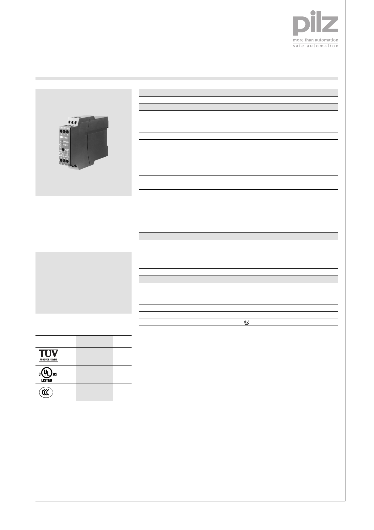
The S1MN thermistor monitoring
relay is used in temperature
monitoring circuits in accordance
with EN 44081 to protect motors,
generators, storage areas etc. from
overheating.
Features
● For DC and AC supplies
● Normally energised mode
● Fault latching or automatic reset
● Manual reset via internal
or external reset button
Approvals
Technical Details
Electrical data
Supply voltage
Tolerance
Power consumption
Usage category in accordance
with EN 60947-4-1
EN 60947-5-1
Output contacts
Contact material
Contact fuse protection in accordance with
EN 60947-5-1
Blow-out fuse quick acting
Blow-out fuse slow acting
Safety cut-out, 24 V AC/DC
characteristic B/C
Measuring circuit
Response value for sensor short-circuit
Delay on energisation
Response value
Release value
Resistance at 20 °C
Mechanical data
Max. cable cross section of ext. conductor
single core
multi-core with crimp connectors
Dimensions (H x W x D)
Weight
Designation
S1MN
AC: 48, 110, 230, 240, 400 V
AC/DC: 24 V
-15 %/+10 %
AC: 3.5 VA, DC: 2 W
AC1: 240 V/0.1 ... 5 A/1200 VA
DC1: 24 V/0.1 ... 5 A/120 W
AC15: 230 V/2 A; DC13: 24 V/1.5 A
2 auxiliary contacts (2 C/O)
AgCdO, 3 µm gold plating for low-load
range 1-50 V/1-100 mA
6 A
4 A
4 A
Approx. 25 Ohm
Approx. 500 ms
3.6 kOhm ± 10 %
1.8 kOhm± 10 %
Max. 1.5 kOhm
1 x 4 mm2, 24 - 10 AWG
2 x 2,5 mm2, 24 - 14 AWG
87 x 22.5 x 121 mm
AC: 160 g; DC: 120 g
II (3) G/D [EEx nL] IIC
4
S1MN
●
●*
●
* for versions up to 240 V AC
Description
The thermistor monitoring relay is
enclosed in an S-95 slimline housing.
There are various AC versions
available and one version for AC/
DC operation.
Features:
● Relay outputs:
2 auxiliary contacts (2 C/O)
● Measuring circuit for connecting
a temperature sensor
(PTC-resistor)
● Monitoring temperature sensor
for short circuits
● LED for supply voltage and faults
A temperature sensor is connected
to the S1MN measuring circuit. If
the temperature exceeds a defined
value, i.e. the resistance of the
temperature sensor reaches the
response value, the output contacts
switch.
If the temperature falls once more,
i.e. the resistance of the temperature
sensor reaches the release value, the
auxiliary contacts switch again if
automatic reset has been selected.
The unit is then ready for operation.
If manual reset is selected, an
internal or external reset button must
be activated. Reset can also occur
by interrupting the supply voltage.
Pilz GmbH & Co. KG, Sichere Automation, Felix-Wankel-Straße 2, 73760 Ostfildern, Germany
Telephone: +49 711 3409-0, Telefax: +49 711 3409-133, E-Mail: pilz.gmbh@pilz.de
NSG-D-2-129-2005-10
Page 2
Electronic Monitoring Relays
Thermistor monitoring
S1MN
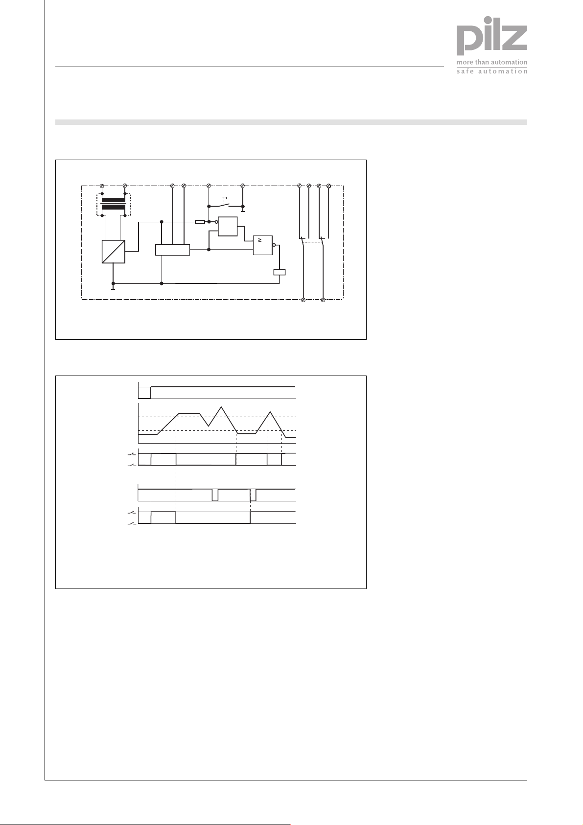
Internal wiring diagram
U
B
A1
(+)
~
G1 F1
=
S1 Reset button
Timing diagram
Measuring circuit Reset circuit
A2
(-)
+
U
B
R
th
R
off
R
on
J
T1 T2
> NAT
Reset circuit
X2
S1
R
S
X1
1
K1
121422 24
K1
11 21
4
11-14, 21 - 24
1
Reset
0
11-14, 21 - 24
UBSupply voltage
RonResponse value
R
Release value
off
RthPTC resistance
Non-latching
Latching
Pilz GmbH & Co. KG, Sichere Automation, Felix-Wankel-Straße 2, 73760 Ostfildern, Germany
Telephone: +49 711 3409-0, Telefax: +49 711 3409-133, E-Mail: pilz.gmbh@pilz.de
NSG-D-2-129-2005-10
Page 3

Electronic Monitoring Relays
Thermistor monitoring
S1MN
Connection examples
L1
L2
L3
1L1
(1L+)
U
B
S1
F2
11 21
A1
X1
T1
X2
S1MN
K2
1L2
(1L-)
PE
12 14 T2
22 24 A2
S2
K2
K2
H1
0V
M1
UVW
M 3 AC
J JJ
4
Pilz GmbH & Co. KG, Sichere Automation, Felix-Wankel-Straße 2, 73760 Ostfildern, Germany
Telephone: +49 711 3409-0, Telefax: +49 711 3409-133, E-Mail: pilz.gmbh@pilz.de
NSG-D-2-129-2005-10
Page 4

4
Electronic Monitoring Relays
Thermistor monitoring
S1MN
General Details
Unless stated otherwise in the technical details for the specific unit.
Electrical data
AC frequency range 50 ... 60 Hz
DC residual ripple 160 %
Contact material AgCdO
Continuous duty 100 %
Environmental data
EMC EN 60947-5-1, EN 61000-6-2
Vibration in accordance
with EN 60068-2-6, 04/95 Frequency: 10 ... 55 Hz
Amplitude: 0.35 mm
Climatic suitability EN 60068-2-78
Airgap creepage EN 60947-1, EN 60079-15
Ambient temperature -10 ... +55 °C
Storage temperature -40 ... +85 °C
Mechanical data
Torque setting for connection terminals
(screws) 0.6 Nm
Mounting position Any
Housing material
Front ABS UL 94 V0
Housing PPO UL 94 V0
Protection types
Mounting: IP 54
Housing: IP 40
Terminals: IP 20
The version of the standards current at 2005-10 apply.
Order references key
UB Supply voltage
Order references
Type U
S1MN 24 V AC/DC 839 400
S1MN 48 V AC 839 405
S1MN 110 V AC 839 410
S1MN 230 V AC 839 415
S1MN 240 V AC 839 420
S1MN 400 V AC 839 425
Additional versions available on request
B
Order no.
Pilz GmbH & Co. KG, Sichere Automation, Felix-Wankel-Straße 2, 73760 Ostfildern, Germany
Telephone: +49 711 3409-0, Telefax: +49 711 3409-133, E-Mail: pilz.gmbh@pilz.de
NSG-D-2-129-2005-10
 Loading...