

Page 1
Electronic Monitoring Relays
Single-phase current monitoring
S1IM
The S1IM current monitoring relay
is used to monitor the maximum
current values for heaters, lamps etc.
Features
● 12 measurement ranges can be
selected from 0.002 to 15 A
● Reaction time can be set for up
to 10 seconds
● Operates to normally energised
or normally de-energised mode
● Galvaninc isolation between
measuring voltage and supply
voltage
● UP version: Measuring inputs
are not polarity-sensitive
Approvals
S1IM
●
Technical Details
Electrical data
Supply voltage
Tolerance
Power consumption
Utilisation category in accordance with
EN 60947-4-1
EN 60947-5-1
Output contacts
Contact material
Contact fuse protection in accordance
with EN 60947-5-1
Measuring circuit
Frequency range
Adjustable measuring range limit values
Hysteresis
Impedance of the measurement inputs
Max. overload
Polarity of the measuring inputs
Reaction time
Temperature variation
Environmental data
Ambient temperature
Mechanical data
Max. cross section of external conductor
Single-core conductor
multi-core conductor with crimp connector
Dimensions (H x W x D)
Weight
The standards current on 2003-05 apply
S1IM
AC: 24, 42-48, 110-130, 230-240 V
DC: 24 V
85 ... 110 %
AC: 2 VA, DC: 1 W
AC1: 240 V/0,1 ... 5 A/1200 VA
DC1: 24 V/0,1 ... 5 A/120 W
AC15: 230 V/2 A; DC13: 24 V/1,5 A
1 auxiliary contact (C/O)
AgCdO, 3 µm gold plating for low-load
range 1-50 V/1-100 mA
max. 6 A quick or max. 4 A slow
Safety cut-out 4 A, Caracteristic B/C
0, 40 ... 400 Hz
0,1 A: 0,1; 0,05; 0,02; 0,01 A
2 A: 2; 1; 0,4; 0,2 A
E: 50 A/25 A/10 A/5 A
60 ... 95 % of the response value
0,1 A: 2,5 Ω
2 A: 125 mΩ
E: 5 mΩ
0,1 A: max. 0,2 A
2 A: max. 2,5 A
E: 15 A/100 ED, 20 A/10 s, 50 A/2 s
Polarised
UP version: any
0,1 ... 10 s
± 0,05% per+1°C
-15 ... +55 °C
1 x 4 mm2, 24 - 10 AWG
2 x 2,5 mm², 24 - 14 AWG
87 x 22,5 x 121 mm
130 g
4
●
Description
The current monitoring relay is enclosed in an S-95 slimline housing.
● Hysteresis factor can be set
● Fault latching or automatic reset
● LEDs for switching status of the
There are 8 versions available for AC
operation and one for DC operation.
Features:
(Description continued overleaf)
● Relay output: 1 auxiliary contact
(C/O)
● 3 measuring circuits for 0.1 A, 2 A
and E each with 4 different ranges
● Response value can be set from
20% to 100% of the measuring
range limit value
Pilz GmbH & Co. KG, Sichere Automation, Felix-Wankel-Straße 2, 73760 Ostfildern, Germany
Telephone: +49 711 3409-0, Telefax: +49 711 3409-133, E-Mail: pilz.gmbh@pilz.de
from 0.6 to 0.9 x I
on
relay and supply voltage
NSG-D-2-008-2006-10
Page 2
Electronic Monitoring Relays
Single-phase current monitoring
S1IM
The S1IM monitors whether a set
current value has been exceeded.
On the UP version the measuring
inputs are not polarity-sensitive.
If the measured current reaches the
response value Ion, the auxiliary
contact 11-14 switches and the LED
is illuminated. If the measured
current falls below the hysteresis
value I
selected, the auxiliary contact
switches again and the LED goes
out. The unit is once again ready for
operation. If faults are latched, the
unit is not ready for operation again
until an external reset button is
activated or the supply voltage has
been switched off and on again.
and automatic reset is
off
4
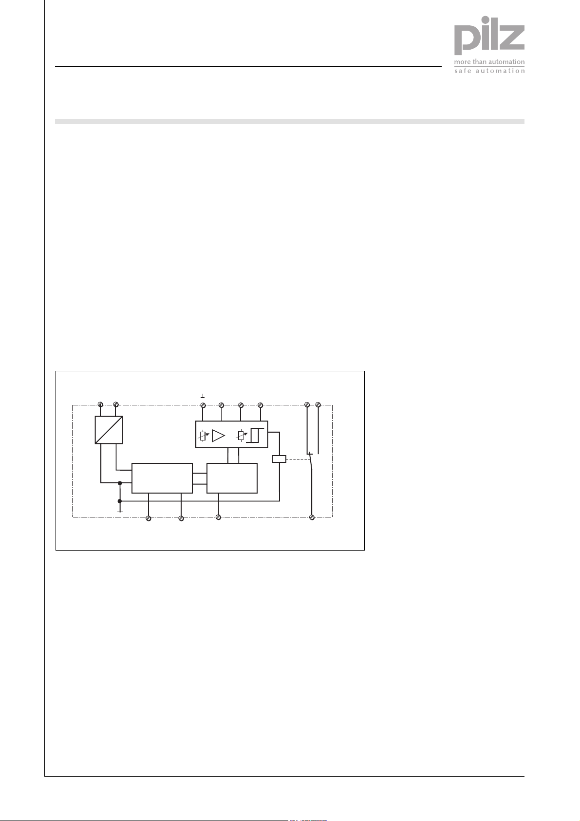
Internal wiring diagram
U
B
A2
A1
(-)
(+)
~
G1
=
Normally energised
(closed circuit) /
normally de-energised
(open circuit)
S1IM
Normally energised (closed circuit) /
normally de-energised (open circuit)
Y1 Y2 Y3
Measurement inputs
2 A E0.1 A
Store
Latching/Non-latching
Auxiliary contact
12 14
K1
11
Pilz GmbH & Co. KG, Sichere Automation, Felix-Wankel-Straße 2, 73760 Ostfildern, Germany
Telephone: +49 711 3409-0, Telefax: +49 711 3409-133, E-Mail: pilz.gmbh@pilz.de
NSG-D-2-008-2006-10
Page 3

Electronic Monitoring Relays
Single-phase current monitoring
S1IM
Timing diagram
Y2
Y2
Non-latching
Normally
I
M
I
on
I
off
11
11
11
11
12
12
14
14
LED
Y3
Y3
de-energised mode
Normally
energised mode
Latching
Normally
de-energised mode
Hysteresis (I
Adjustable hysteresis
): 0.6 to 0.95 I
off
on
t1: Reaction time
Ia: IM > Ion: once tR has elapsed, the
relay energises and the LED
“OUT” is illuminated.
IM > I
: Relay de-energises and
off
LED goes out
IIa: IM > I
relay remains de-energised
before tRhas elapsed:
on
Ib:I
> Ion: as above, but relay
M
de-energises and LED “Out”
goes out.
IM > I
: relay energises and LED
off
is illuminated.
IIb: as above, but relay remains
energised
III: IM > Ion: see above
IM < I
: relay de-energises once
off
Y2 - Y3 is open.
4
Pilz GmbH & Co. KG, Sichere Automation, Felix-Wankel-Straße 2, 73760 Ostfildern, Germany
Telephone: +49 711 3409-0, Telefax: +49 711 3409-133, E-Mail: pilz.gmbh@pilz.de
NSG-D-2-008-2006-10
Page 4

Electronic Monitoring Relays
Single-phase current monitoring
S1IM
Connection examples
● Example 1
Normally energised, non-latching
1L1
U
B
1 L2
11
A1
E
2 A
0,1 A
Y1
12
14
R
L
I
M
Y3
Y2
A2
● Example 2
Normally de-energised, non-latching
1L1
U
B
1 L2
● Example 3
Normally de-energised, latching
1L1
U
B
1 L2
11
A1
E
2 A
0,1 A
Y1
12
Y2
14
R
L
I
M
Y3
A2
● Example 4
Normally energised, latching
1L1
U
B
1 L2
4
A1
0,1 A
Y1
12
2 A
14
11
E
R
L
I
M
Y3
Y2
A2
A1
0,1 A
Y1
12
2 A
11
E
R
L
I
M
Y3
Y2
A2
14
Pilz GmbH & Co. KG, Sichere Automation, Felix-Wankel-Straße 2, 73760 Ostfildern, Germany
Telephone: +49 711 3409-0, Telefax: +49 711 3409-133, E-Mail: pilz.gmbh@pilz.de
NSG-D-2-008-2006-10
Page 5

Electronic Monitoring Relays
Single-phase current monitoring
S1IM
General Details
Unless stated otherwise in the technical details for the specific unit.
Electrical data
AC frequency range 50 ... 60 Hz
DC residual ripple 160 %
Contact material AgCdO
Continuous duty 100 %
Environmental data
EMC EN 60947-5-1, EN 61000-6-2
Vibration in accordance with EN 60068-2-6
Frequency 10 ... 55 Hz
Amplitude 0.35 mm
Climatic suitability EN 60068-2-78
Airgap creepage DIN VDE 0110-1
Ambient temperature -10 ... +55 °C
Storage temperature -40 ... +85 °C
Mechanical data
Torque setting for connection terminals 0.6 Nm (screws)
Mounting position Any
Housing material
Front ABS UL 94 V0
Housing PPO UL 94 V0
Protection types
Mounting IP54
Housing IP40
Terminals IP20
Order references key
UB Supply voltage
IMMeasuring current
Order reference
Type U
S1IM 24 V DC 15 A 828 010
S1IM 24 V AC 15 A 828 020
S1IM 42 V AC 15 A 828 030
S1IM 110-130 V AC 15 A 828 040
S1IM 230-240 V AC 15 A 828 050
S1IM UP 24 V DC 15 A 828 035
Additional versions available on request
B
I
M
Order no.
4
Pilz GmbH & Co. KG, Sichere Automation, Felix-Wankel-Straße 2, 73760 Ostfildern, Germany
Telephone: +49 711 3409-0, Telefax: +49 711 3409-133, E-Mail: pilz.gmbh@pilz.de
NSG-D-2-008-2006-10
 Loading...