

Page 1
Electronic Monitoring Relays
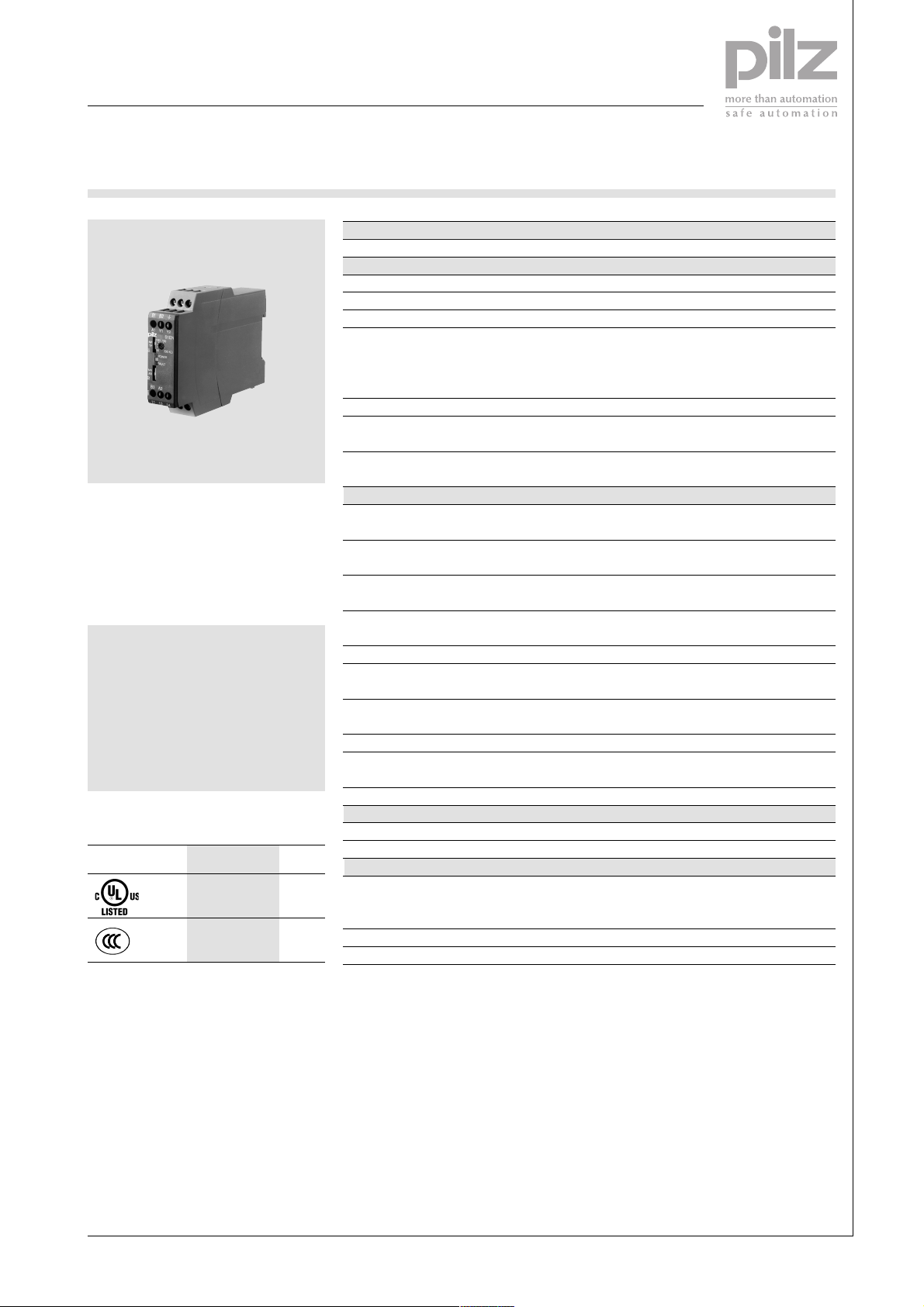
Insulation monitoring
S1EN
Technical Details S1EN
Electrical data
Supply voltage AC/DC: 24 ... 240 V
Tolerance 85 ... 110 %
Power consumption 240 V AC 5 VA, 24 V DC: 1 W
Switching capability in accordance
with EN 60947-4-1, 10/91 AC1: 240 V/0.1 ... 5 A/1200 VA
EN 60947-5-1, 10/91 AC15: 230 V/2 A; DC13: 24 V/1.5 A
Output contacts 1 auxiliary contact (C/O)
Contact material AgCdO, 3 µm gold plating for low-load
Contact fuse protection in accordance Max. 6 A quick or max. 4 A slow
with EN 60947-5-1, 10/91
Measuring circuit
The insulation monitoring relay S1EN
provides protection against insulation
faults in galvanically isolated voltage
supply networks (IT systems). It
meets the requirements of DIN EN
61557-8.
Features
● For DC and AC supplies
● Normally energised mode
● Fault latching or automatic reset
● Normal/test operation
● External reset button can be
connected
Approvals
S1EN
●
Rated mains voltage 50 kΩ version: AC/DC: 0 ... 240 V
(monitored mains) 200 kΩ version: AC/DC: 0 ... 400 V
Response value
Release value
Max. measuring current (DC)
Max. measuring voltage (DC) ± 17 V
Max. permitted external voltage (AC/DC) 50 kΩ version: 264 V
Min. impedance (AC/DC) 50 kΩ version: 75 kΩ
Max. permitted line capacitance 1 µF
Max. response error in accordance with ± 15%
DIN EN 61557-8 (05/98)
Reaction time 10 s
Environmental data
Climatic suitability IEC 60721-3-3, 1995
Condensation and icing Not permitted
Mechanical data
Max. cable cross section of ext. conductor 1 x 4 mm2 or 2 x 1.5 mm
DC1: 24 V/0.1 ... 5 A/120 W
range 1-50 V/1-100 mA
50 kΩ version: 12.5 ... 50 kΩ, adjustable
200 kΩ version: 50 ... 200 kΩ, adjustable
50 kΩ version:
200 kΩ version: Response value + ca. 20 kΩ
50 kΩ version:
200 kΩ version:
200 kΩ version: 460 V
200 kΩ version: 300 kΩ
Response value + ca. 5 kΩ
2.4 mA
1.0 mA
2
4
●
Dimensions (H x W x D) 87 x 22.5 x 122 mm
Weight 150 g
Description
Features:
● Relay outputs: 1 auxiliary contact
The earth fault monitoring relay is
enclosed in an S-95 slimline housing.
There are two versions available with
● Two insulation measuring circuits
● Detects symmetrical insulation
measuring ranges of 50 kΩ and
200 kΩ. The universal power supply
can be used with all supply voltages.
● Switch for function testing
● LED display for supply voltage
(See next page for function
description)
Pilz GmbH & Co. KG, Sichere Automation, Felix-Wankel-Straße 2, 73760 Ostfildern, Germany
Telephone: +49 711 3409-0, Telefax: +49 711 3409-133, E-Mail: pilz.gmbh@pilz.de
(C/O)
faults
and faults
NSG-D-2-127-2005-04
Page 2
Electronic Monitoring Relays
Insulation monitoring
S1EN
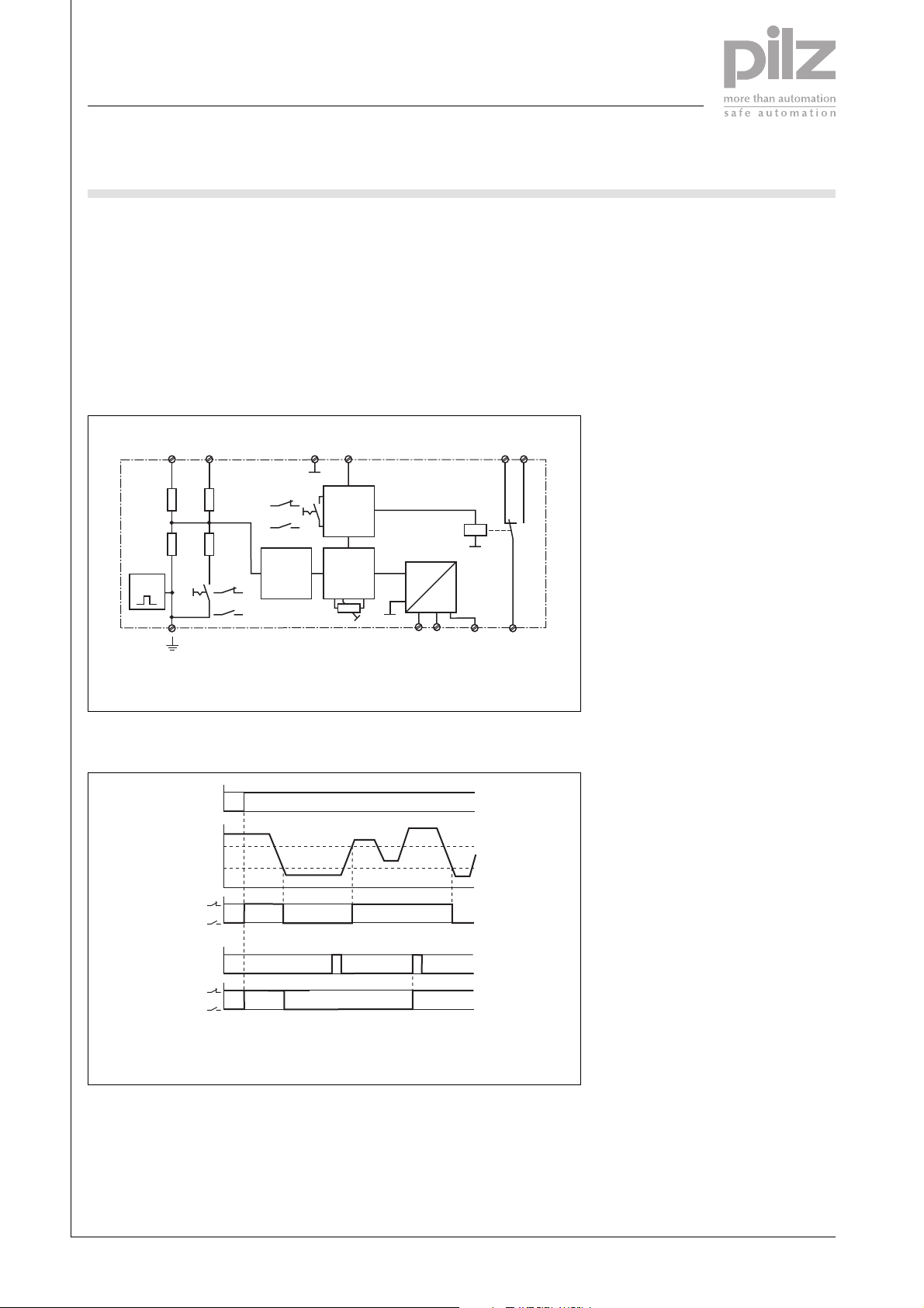
The device measures the insulation
resistance between the phases and
system earth in galvanically isolated
voltage supplies. If the insulation
resistance in one of the two measuring circuits falls below the response
value Ron, the auxiliary contact
switches over and the fault LED
Internal wiring diagram
Measuring circuit,
G
N
B1 B2
Test:
Normal:
AR:
MR:
Evaluation
UNMains voltage
RonResponse value
lights up. If resistance then exceeds
the release value R
immediately ready for operation if
the device is
off
automatic reset is selected. If manual
reset is selected an external button
or the MR/AR switch must be
operated
ResetU
Y1 Y2
Nonlatching/
latching
RE ≤ R
R
an
an
24 V DC
AC/DC:
24 ... 240 V
A1
U
K1
A2
B3
B
UB to B3-A2: 24 V AC/DC
UB to A1-A2: 42-240 V AC/DC
12
14
11
4
Timing diagram
U
B
R
E
R
off
R
on
11 - 14
Reset
11 - 14
UBSupply voltage
RonResponse value
Non-latching
1
0
Latching
R
Release value
off
REInsulation resistance
Pilz GmbH & Co. KG, Sichere Automation, Felix-Wankel-Straße 2, 73760 Ostfildern, Germany
Telephone: +49 711 3409-0, Telefax: +49 711 3409-133, E-Mail: pilz.gmbh@pilz.de
NSG-D-2-127-2005-04
Page 3

Electronic Monitoring Relays
Insulation monitoring
S1EN
Connection examples
● Example 1
AC application circuit
L1
N
1L1
1L2
PE
F1
U
B
● Example 2
3AC application circuit
L1
L2
L3
1L1
1L2
PE
U
N
B2
B1
Y1A1
S1EN
B3 A2
11 12 14
U
T1
N
F2
R
E
R
Y2
E1
E
4
F1
U
U
B
N
B2
B1
Y1A1
S1EN
B3 A2
11 12 14
Y2
T1
U
NUN
F2
R
R
E
E1
E
Pilz GmbH & Co. KG, Sichere Automation, Felix-Wankel-Straße 2, 73760 Ostfildern, Germany
Telephone: +49 711 3409-0, Telefax: +49 711 3409-133, E-Mail: pilz.gmbh@pilz.de
NSG-D-2-127-2005-04
Page 4

Electronic Monitoring Relays
Insulation monitoring
S1EN
● Example 3
3AC/DC application circuit
L1
L2
L3
1L1
1L2
PE
alternativ
F1
U
U
N
B
Alternatively
T1
F2
G1
U
N
4
● Example 4
DC application circuit
L1
N
1L1
1L2
PE
F1
B2
B1
Y1A1
S1EN
B3 A2
11 12 14
R
E
R
Y2
E1
T1
E
U
N
~
G1
=
U
N
F2
U
U
B
N
B2
B1
Y1A1
S1EN
B3 A2
11 12 14
R
E
R
Y2
E1
E
Pilz GmbH & Co. KG, Sichere Automation, Felix-Wankel-Straße 2, 73760 Ostfildern, Germany
Telephone: +49 711 3409-0, Telefax: +49 711 3409-133, E-Mail: pilz.gmbh@pilz.de
NSG-D-2-127-2005-04
Page 5

Electronic Monitoring Relays
Insulation monitoring
S1EN
General Details
Unless stated otherwise in the technical details for the specific unit.
Electrical data
AC frequency range 50 ... 60 Hz
DC residual ripple 160 %
Contact material AgCdO
Continuous duty 100 %
Environmental data
EMC EN 50081-2, 01/92; EN 50082-2, 03/95
Vibration in accordance Frequency: 10 ... 55 Hz
with EN 60068-2-6, 04/95 Amplitude: 0.35 mm
Climatic suitability IEC 60068-2-3, 1969
Airgap creepage DIN VDE 0110-1, 04/97
Ambient temperature -10 ... +55 °C
Storage temperature -40 ... +85 °C
Mechanical data
Torque setting for connection terminals 0.6 Nm (screws)
Mounting position Any
Housing material Thermoplast Noryl SE 100
Protection types Mounting: IP54
Housing: IP40
Terminals: IP20
Order references key
U
Supply voltage
B
R
Response value
on
Order reference
Type U
S1EN 24-240 VAC/DC 50 KΩ 884 100
S1EN 24-240 VAC/DC 200 KΩ 884 110
B
R
on
Order no.
4
Pilz GmbH & Co. KG, Sichere Automation, Felix-Wankel-Straße 2, 73760 Ostfildern, Germany
Telephone: +49 711 3409-0, Telefax: +49 711 3409-133, E-Mail: pilz.gmbh@pilz.de
NSG-D-2-127-2005-04
 Loading...