


20 181-04
PZE X5/PZE X5V
4
D Betriebsanleitung
4
GB Operating instructions
4
F Manuel d'utilisation
Sicherheitsbestimmungen
• Das Gerät darf nur von Personen installiert
und in Betrieb genommen werden, die mit
dieser Betriebsanleitung und den geltenden
Vorschriften über Arbeitssicherheit und
Unfallverhütung vertraut sind. Beachten Sie
die VDE- sowie die örtlichen Vorschriften,
insbesondere hinsichtlich der Schutzmaßnahmen.
• Beim Transport, bei der Lagerung und im
Betrieb die Bedingungen nach EN 60068-26 einhalten (s. techn. Daten).
• Durch Öffnen des Gehäuses oder eigenmächtige Umbauten erlischt die Gewährleistung.
• Montieren Sie das Gerät in einen Schaltschrank; Staub und Feuchtigkeit können
sonst zu Beeinträchtigungen der Funktionen führen.
• Sorgen Sie an allen Ausgangskontakten bei
kapazitiven und induktiven Lasten für eine
ausreichende Schutzbeschaltung.
Bestimmungsgemäße Verwendung
Der Kontaktblock PZE X5 dient als Erweiterungsgerät zur Kontaktverstärkung und
Kontaktvervielfältigung. Der Kontaktblock
PZE X5V dient zusätzlich zum zeitlich
verzögerten Weiterschalten eines NOT-AUSBefehls in Sicherheitsstromkreisen.
Das Gerät ist bestimmt für den Einsatz in
• Anwendungsschaltungen mit NOT-AUSSchaltgeräten, Schutztürwächtern und
Zweihandbedienungsrelais
•
Sicherheitsstromkreisen nach VDE 0113-1
und EN 60204-1
Das Gerät darf nur mit Grundgeräten verwendet werden, die einen Rückführkreis
besitzen.
Die zu realisierende Kategorie nach EN 954-1
ist abhängig von der Kategorie des Grundgeräts. Sie kann vom Kontakterweiterungsblock nicht überschritten werden.
Safety Regulations
• The unit may only be installed and operated
by personnel who are familiar with both
these instructions and the current
regulations for safety at work and accident
prevention. Follow local regulations
especially as regards preventative
measures.
• Transport, storage and operating conditions
should all conform to
Technical Data)
• Any guarantee is void following opening of
the housing or unauthorised modifications.
• The unit should be panel mounted,
otherwise dampness or dust could lead to
functional impairment.
• Adequate fuse protection must be provided
on all output contacts with capacitive and
inductive loads.
EN 60068-2-6 (see
.
Typical Applications
The contact block PZE X5 is an expander
module used to provide additional contacts.
The contact block PZE X5V has delay off
contacts for use in Emergency Stop circuits
The unit is for use in
• Applications together with Emergency Stop
Relays, Safety Gate Monitors and TwoHand Controls
• Safety circuits according to VDE 0113-1
and EN 60204-1
The unit may only be used together with a
base unit which has a feedback control loop.
The category to be implemented in
accordance with EN 954-1 depends on the
category of the base module. It cannot be
exceeded by the expander module.
Conseils préliminaires
• La mise en oeuvre de l'appareil doit être
effectuée par une personne spécialisée en
installations électriques, en tenant compte
des prescriptions des différentes normes
applicables (NF, EN, VDE..), notamment
au niveau des risques encourus en cas de
défaillance de l'équipement électrique.
• Respecter les exigences de la norme
EN 60068-2-6 lors du transport, du
stockage et de l'utilisation de l'appareil (voir
les caractéristiques techniques).
• Toutes interventions sur le boîtier
(ouverture du relais, échange ou modification de composants, soudure etc..) faites
par l'utilisateur annulent la garantie.
• Montez l'appareil dans une armoire
électrique à l'abri de l'humidité et de la
poussière.
• Assurez-vous du pouvoir de coupure des
contacts de sortie en cas de charges
inductives ou capacitives.
Domaines d'utilisation
Le relais PZE X5 est un bloc d'extension qui
permet d'augmenter le nombre et le pouvoir
de coupure des contacts de sécurité. La
variante PZE X5V est un bloc d'extension
temporisé à la retombée.
Le PZE X5/PZE X5V peut être utilisé avec :
• les relais d'arrêt d'urgence, les relais de
surveillance protecteurs et les commandes
bimanuelles.
• dans les circuits de sécurité d'après les
normes VDE 0113-1 et EN 60204-1
Le PZE X5/PZE X5V ne peut être piloté que
par des relais de sécurité ayant une boucle de
retour.
La catégorie à réaliser selon l’EN 954-1
dépend de la catégorie de l’appareil de base.
Elle ne peut pas être dépassée par le bloc
d’extension de contacts.
Gerätebeschreibung
Der Kontaktblock ist in einem P-97-Gehäuse
untergebracht. Die Versorgungsspannung
beträgt 24 V DC (PZE X5, PZE X5V) bzw.
48 V DC (PZE X5V)
Merkmale:
• Relaisausgänge:
5 Sicherheitskontakte (S), zwangsgeführt
• Statusanzeige für Ausgangsrelais und
Versorgungsspannung
• Anschluss für Rückführkreis
• einkanalige Ansteuerung ohne
Querschlusserkennung
• zweikanalige Ansteuerung mit oder ohne
Querschlusserkennung
• abschaltbare Rückfallverzögerung
(nur PZE X5V)
Die Sicherheitseinrichtung bleibt auch
wirksam bei:
- Spannungsausfall
- Ausfall eines Bauteils
Description
The Contact Block is enclosed in a P-97
housing. There is available for 24 V DC
(PZE X5, PZE X5V) or 48 V DC (PZE X5V)
operation.
Features:
• Relay outputs:
5 safety contacts (n/o), positive-guided
• Status indicators for output relay and
operating voltage
• Connections for a feedback control loop
• Single channel operation without shortcircuit recognition
• Two channel operation with or without shortcircuit recognition
• Delay time switch off (reset)
(only PZE X5V)
The safety function remains effective in the
following cases:
- Power supply failure
- Component failure
- 1 -
Description de l'appareil
Inséré dans un boîtier P-97. Sa tension
d'alimentation est de 24 V DC (PZE X5,
PZE X5V) ou 48 V DC (PZE X5V).
Particularités :
• Contacts de sortie :
5 contacts à fermeture de sécurité
• LEDs de visualisation pour tension
d'alimentation et relais de sortie
• Bornes pour boucle de retour
• Commande par 1 canaux sans détection
des courts-circuits
• Commande par 2 canaux avec ou sans
détection des courts-circuits
• inhibition de la temporisation
(PZE X5V uniquement)
La sécurité est garantie, même dans les cas
suivants :
- Défaillance tension
- Défaillance d'un composant
- Spulendefekt
- Leiterbruch
- Erdschluss
- Coil defect in a relay
- Cable break
- Earth fault
- Défaillance bobine
- Défaut soudure
- Défaut de masse
Funktionsbeschreibung
Der Kontaktblock PZE X5, PZE X5V ist ein
Zusatzgerät und dient der Erweiterung eines
Sicherheitsstromkreises. Der Kontaktblock
wird von einem Grundgerät z. B. NOT-AUSSchaltgerät angesteuert.
Sobald die Versorgungsspannung UB anliegt
(LED "POWER" leuchtet) und die Eingangskreise 1 und 2 geschlossen sind, gehen die
beiden Ausgangsrelais K1 und K2 in Arbeitsstellung. Die Sicherheitskontakte 13-14, 2324, 33-34, 43-44, 53-54 (PZE X5) bzw. 17-18,
27-28, 37-38, 47-48, 57-58 (PZE X5V)
schließen. Die LEDs "CH. 1" und "CH. 2"
leuchten.
Werden einer oder beide Eingangskreise
geöffnet, fallen die Relais K1 und/oder K2
sofort (PZE X5) bzw. nach Ablauf der
Verzögerungszeit (PZE X5V) ab. Die
zwangsgeführten Sicherheitskontakte 13-14,
23-24, 33-34, 43-44, 53-54 (PZE X5) bzw. 17-
Function Description
The Contact block PZE 5XP, PZE X5V is an
add-on unit for expansion of a safety circuit.
The Contact block is controlled by a base unit
(e.g. E-Stop Relay).
When the operating voltage U
(LED "POWER" is illuminated) and the input
circuits 1 and 2 are closed, the two output
relays K1 and K2 energise. The safety
contacts 13-14, 23-24, 33-34, 43-44, 53-54
(PZE X5) or 17-18, 27-28, 37-38, 47-48, 57-58
(PZE X5V) close. The LED's "CH. 1" and
"CH. 2" illuminate.
If both of the input circuits are opened, or only
one, relays K1 and/or K2 de-energise
immediately (PZE X5) or once the delay-on
de-energisation period has elapsed (PZE
X5V). The positive-guided safety contacts
13-14, 23-24, 33-34, 43-44, 53-54 (PZE X5) or
17-18, 27-28, 37-38, 47-48, 57-58 (PZE X5V)
open.
18, 27-28, 37-38, 47-48, 57-58 (PZE X5V)
öffnen.
PZE X5 PZE X5V
A1
UK1
Y1 2313 33 435453UK1 K2
is supplied
B
A1
Description du fonctionnement
Le relais PZE X5P, PZE X5V est un bloc
d'extension qui permet d'augmenter le nombre
des contacts de sécurité. Le PZE X5P est
piloté par un bloc logique de base (par ex.
relais d'arrêt d'urgence PNOZ).
Dès que la tension d'alimentation UB est
présente (la LED "POWER" est allumée) et
les canaux d'entrée U-K1 et U-K2 sont
fermés, les relais K1 et K2 passent en
position travail. Les contacts de sécurité 1314, 23-24, 33-34, 43-44, 53-54 (PZE X5) ou
17-18, 27-28, 37-38, 47-48, 57-58 (PZE X5V)
se ferment. Les LED's de visualisation "CH.
1" et "CH. 2" s'allument.
Si le circuit d'entrée est ouvert, les relais K1
et K2 retombent instantanément (PZE X5) ou
après écoulement de la temporisation (PZE X5V). Les contacts de sécurité 1314, 23-24, 33-34, 43-44, 53-54 (PZE X5) ou
17-18, 27-28, 37-38, 47-48,57-58 (PZE X5V)
s'ouvrent.
UK1
Y1 2717 37 475857UK1 K2
K1
A2
K2
Y4 Y3
Y2K214 24K134 44
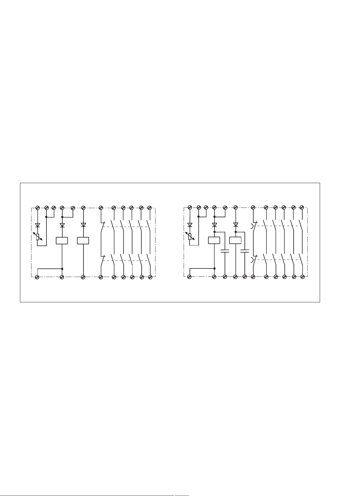
Fig. 1: Schematisches Schaltbild/Wiring diagram/Schéma interne
Sicherheitsfunktionen
Der Kontaktblock erweitert einen bestehenden
Sicherheitsstromkreis. Da die Ausgangsrelais
durch den Rückführkreis des Grundgerätes
überwacht werden, übertragen sich die
Sicherheitsfunktionen des bestehenden
Stromkreises auf den Kontaktblock.
Wird nach EN 60204 T 9.4.3.1 L
i(-) der
Versorgungsspannung auf Erdpotenzial
gelegt, werden in den Eingangskreisen
Erdschlüsse erkannt. Die
Erdschlusssicherheit im Rückführkreis ist
Safety Functions
The Contact block expands an existing safety
circuit. As the output relays are monitored
via the feedback control loop of the base unit,
the safety functions of the existing safety
circuit are transferred to the contact block.
L(-) of the operating voltage is connected to
the earth potential according to EN 60204 Pt.
9.4.3.1, earth faults are detected in the input
circuits. The earth fault safety in the
feedback control loop is dependent on the
base unit used.
vom verwendeten Grundgerät abhängig.
A2
K1
Y4 Y3
Y6 Y5
K2
+
+
Y2K218 28K138 48
Fonctions de sécurité
Le bloc d'extention permet d'augmenter le
nombre de contacts de sécurité d'un bloc
logique de sécurité. L'auto-contrôle des
relais internes est réalisé par l'appareil de
base à l'aide de la boucle de retour. Ainsi les
contacts du bloc d'extension ont le même
niveau de sécurité que ceux du bloc logique
de base.
La mise à la terre L(-) de la tension
d'alimentation ou le câblage de la prise de
terre (EN 60204 art. 9.4.3.1) permet de
détecter la mise à la terre des circuits
d'entrée. La détection de la mise à la terre de
la boucle de retour est assurée par l'appareil
de base.
- 2 -

Betriebsarten
• Einkanalige Ansteuerung
- ein Eingangskreis wirkt auf beide
Ausgangsrelais
• Zweikanalige Ansteuerung
- zwei redundante Eingangskreise
wirken auf je ein Ausgangsrelais
- Ausfallsicherheit gegen Kurzschluss
eines Eingangskreises
- zusätzlich Querschlusserkennung
möglich
Operating Modes
• Single channel operation
- one input circuit operates both channels
(bridge K1-K2)
• Two channel operation
- two redundant (i.e. identical) input
circuits each operate one output relay
- additional fail-safety to protect against
short-circuits in one of the input circuits
- short-circuit recognition possible
Modes de fonctionnement
• commande par 1 canal
- le circuit d'entrée agit sur les 2 relais
internes (pont entre K1-K2)
• commande par 2 canaux
- 2 circuits d'entrée identiques agissent
chacun sur un relais interne.
- permet de détecter la défaillance d'un
des circuits d'entrée.
- détection des courts-circuits possible
Montage
Das Gerät muss in einen Schaltschrank mit
einer Schutzart von mind. IP54 eingebaut
werden. Zur Befestigung auf einer Normschiene hat das Gerät ein Rastelement auf
der Rückseite.
Sichern Sie das Gerät bei Montage auf einer
senkrechten Tragschiene (35 mm) durch ein
Halteelement wie z. B. Endhalter oder
Endwinkel.
Inbetriebnahme
Beachten Sie bei der Inbetriebnahme:
• Vor die Ausgangskontakte eine Sicherung (siehe technische Daten) schalten,
um das Verschweißen der Kontakte zu
verhindern.
• Berechnung der max. Leitungslänge I
am Eingangs- und Rückführkreis:
R
I
max
R
widerstand (s. technische Daten)
lmax
=
Rl / km
= max. Gesamtleitungs-
lmax
Rl /km = Leitungswiderstand/km
• Keine kleinen Ströme (z. B. 30 mA) mit
Kontakten schalten, über die zuvor große
Ströme geführt wurden.
• Leitungsmaterial aus Kupferdraht mit einer
Temperaturbeständigkeit von 60/75 °C
verwenden.
• Angaben im Kapitel "Technische Daten"
unbedingt einhalten.
Anschluss
• Versorgungsspannung an Klemmen A1 (+)
und A2 (-) anschließen.
• Eingangskreis
- Einkanalige Ansteuerung:
Sicherheitskontakt an K1 und U
anschließen; Brücke zwischen K1-K2
und Y3-Y4.
- Zweikanalige Ansteuerung ohne Quer-
schlusserkennung:
Sicherheitskontakte an K1 und U und an
K2 und U anschließen, Brücke zwischen
Y3-Y4
- Zweikanalige Ansteuerung mit
Querschlusserkennung:
Sicherheitskontakte an K1 und U und an
Y3 und Y4 anschließen, Brücke
zwischen K2-U
- Abschaltbare Rückfallverzögerung (nur
PZE X5V): Öffnen der Verbindungen Y3Y5 und Y4-Y6, siehe Fig. 8: Öffner-
kontakte zwischen Y3-Y5 und Y4-Y6
• Rückführkreis
Klemmen Y1 und Y2 mit dem Rückführkreis des Grundgerätes verbinden.
max
Installation
The unit must be panel mounted (min. IP54).
There is a notch on the rear of the unit for
DIN-Rail attachment.
If the unit is installed on a vertical mounting
rail (35 mm), ensure it is secured using a
fixing bracket such as end bracket.
Operation
Please note for operation:
• To prevent a welding together of the
contacts, a fuse (see technical details)
must be connected before the output
contacts.
• Calculating the max. cable runs I
input and feedback circuit:
R
I
max
R
resistance (see Technical details)
lmax
=
Rl / km
= max. overall cable
lmax
Rl /km = cable resistance/km
• Low currents (e.g. 30 mA) should not be
switched across contacts across which
high currents have previously been
switched.
• Use copper wiring that will withstand
60/75 °C
• Important details in the section "Technical
Data" should be noted and adhered to.
Connection
• Connect the operating voltage between
A1i(+) and A2 (-).
• Input circuit
- Single channel operation:
Connect the safety contacts to K1 and
U; bridge K1-K2 and Y3-Y4.
- Two channel operation without short-
circuit recognition:
Connect the safety contacts to K1, U
and K2, U; bridge Y3-Y4.
- Two channel operation with short-circuit
recognition:
Connect the safety contacts to K1, U
and Y3, Y4; bridge K2-U.
- Delay time switch off (reset)
(only PZE X5V): Open the connections
Y3-Y5 and Y4-Y6, see fig. 8:
NC contact to Y3-Y5 and Y4-6
• Feedback control loop
Connect terminals Y1 and Y2 with the
feedback control loop of the base unit.
max
at the
Montage
Le relais doit être installé dans une armoire
équipée d'une protection IP54. Sa face
arrière permet un montage sur rail DIN.
Immobilisez l'appareil monté sur un rail DIN
vertical (35 mm) à l'aide d'un élément de
maintien comme par ex. un support ou une
équerre terminale.
Mise en oeuvre
Remarques préliminaires :
• Installez des fusibles (voir les caractéristiques techniques) en amont des
contacts de sortie pour éviter leur
soudage.
• Calcul de la longueur maximale de
conducteur I
boucle de retour :
=
I
max
R
= résistance max. totale du câble
lmax
(voir les caractéristiques techniques)
Rl /km = résistance du câble/km
• Ne pas commuter de faibles intensités
(ex. 30 mA) par des contacts ayant au
préalable commutés des intensités plus
élevées
• Utiliser uniquement des fils de cablâge en
cuivre 60/75 °C.
• Respectez les données indiquées dans
les caractéristiques techniques
Branchement
• Amener la tension d'alimentation (A1-A2).
• Circuit d'entrée
- commande par 1 canal :
câbler le contact sur K1 et U; ponter
K1-K2 et Y3-Y4.
- comande en 2 canaux sans détection
des courts-circuits:
câbler les contacts sur K1, U et K2,
U2; ponter Y3-Y4
- comande en 2 canaux avec détection
des courts-circuits:
câbler les contacts sur K1, U et Y3,
Y4; ponter K2-U
- inhibition de la temporisation
(PZE X5V uniquement): ouverture des
circuits Y3-Y5 et Y4-Y6, voir fig. 8:
contact à ouverture Y3-Y5 et Y4-Y6
• Boucle de retour
Relier les bornes Y1 et Y2 avec la boucle
de retour de l'appareil de base
sur le circuit d’entrée et la
max
R
lmax
Rl / km
Ablauf
Das Gerät ist eingeschaltet, wenn
• die Versorgungsspannung anliegt (LED
"POWER" leuchtet)
• die Eingangskreise geschlossen sind
To operate
The unit is activated when:
• The operating voltage is supplied (LED
"POWER" is illuminated)
• the input circuits are closed
- 3 -
Mise en oeuvre
L'appareil est activé lorsque :
• la tension d'alimentation est appliquée
(LED "POWER" s'allume).
• les canaux d'entrée sont fermés.

Die Sicherheitskontakte 13-14, 23-24, 3334, 43-44, 53-54 (PZE X5) bzw. 17-18, 2728, 37-38, 47-48, 57-58 (PZE X5V) sind
geschlossen und die LEDs "CH. 1" und
"CH. 2" leuchten. Wird der Eingangskreis
geöffnet, öffnen die Sicherheitskontakte
13-14, 23-24, 33-34, 43-44, 53-54 (PZE X5)
sofort bzw. 17-18, 27-28, 37-38, 47-48, 57-58
(PZE X5V) zeitlich verzögert.
The safety contacts 13-14, 23-24, 33-34,
43-44, 53-54 (PZE X5) or 17-18, 27-28, 3738, 47-48, 57-58 (PZE X5V) are closed and
the LED's "CH. 1" and "CH. 2" are
illuminated. If the input circuit is opened, the
safety contacts 13-14, 23-24, 33-34, 43-44,
53-54 (PZE X5) open immediately or 17-18,
27-28, 37-38, 47-48, 57-58 (PZE X5V) after
the delayed time has elapsed.
Les contacts de sécurité 13-14, 23-24, 3334, 43-44, 53-54 (PZE X5) ou 17-18, 27-28,
37-38, 47-48, 57-58 (PZE X5V) sont fermés
et les LED's de visualisation "CH. 1" et "CH.
2" s'allument. Si le circuit d'entrée est ouvert,
les relais K1 et K2 retombent instantanément
13-14, 23-24, 33-34, 43-44, 53-54 (PZE X5)
ou après écoulement de la temporisation 1718, 27-28, 37-38, 47-48, 57-58 (PZE X5V).
Les contacts de sécurité s'ouvrent.
Anwendung
Bitte beachten Sie, dass die Sicherheitsfunktionen des bestehenden Stromkreises
nur erhalten bleiben, wenn der Kontaktblock
wie in Fig. 2 ... 8 gezeigt angeschlossen
wird. Es können nur Grundgeräte mit
Rückführkreis verwendet werden. Die
zweikanalige Ansteuerung ist für Anwendungen mit hohen Sicherheitsanforderungen.
L+
13 14 23 24
Grundgerät
Base unit
Appareil de base
Y1 Y2
K1 K1 K2 13 23 33
A1 U U Y1 43 53
A2 Y3 Y4 Y2 44
Application
Please note that the safety functions of the
existing circuit are only maintained when the
contact block is connected as shown in Fig.
2 ... 8. Only base units with feedback
control loops may be used. Two channel
control is for use in applications with high
safety requirements.
L+
13 14 23 24
PZE X5
54
14 24 34
Grundgerät
Base unit
Appareil de base
Utilisation
Le niveau de sécurité des contacts des blocs
d'extension n'est garanti que si le relais est
câblé comme représenté dans les fig. 2 ... 8.
Seuls des blocs logiques avec une boucle de
retour peuvent être utilsés. La commande en 2
canaux est prévue pour les applications
nécessitant un haut niveau de sécurité.
K1 K1 K2 17 27 37
A1 U U Y1 47 57
PZE X5V
Y1 Y2
A2 Y3 Y5 Y2 48
Y6Y4
18 28 38
58
L-
Fig. 2: PZE X5: Einkanalige Ansteuerung/
Single Channel control
Commande par un canal
L+
13 14 23 24
Grundgerät
Base unit
Appareil de base
Y1 Y2
L-
K1 K1 K2 13 23 33
A1 U U Y1 43 53
PZE X5
A2 Y3 Y4 Y2 44
14 24 34
54
Fig. 4: PZE X5: Zweikanalige Ansteuerung ohne
Querschlusserkennung/Two channel control without
short-circuit recognition/Commande par deux canaux
sans détection des courts-circuits
L-
Fig. 3: PZE X5V: Einkanalige Ansteuerung
Single Channel control
Commande par un canal
L+
13 14 23 24
Grundgerät
Base unit
Appareil de base
Y1 Y2
L-
K1 K1 K2 17 27 37
A1 U U Y1 47 57
PZE X5V
A2 Y3 Y5 Y2 48
Y4 Y6
18 28 38
58
Fig. 5: PZE X5V: Zweikanalige Ansteuerung ohne
Querschlusserkennung/Two channel control without
short-circuit recognition/Commande par deux canaux
sans détection des courts-circuits
- 4 -

Y3 Y5
Y4 Y6
L+
L+
13 14 23 24
Grundgerät
Base unit
Appareil de base
Y1 Y2
L-
K1 K1 K2 13 23 33
A1 U U Y1 43 53
PZE X5
A2 Y3 Y4 Y2 44
14 24 34
54
Fig. 6: PZE X5: Zweikanalige Ansteuerung mit
Querschlusserkennung/Two channel control with shortcircuit recognition/Commande par deux canaux avec
détection des courts-circuits
13 14 23 24
Grundgerät
Base unit
Appareil de base
Y1 Y2
L-
K1 K1 K2 17 27 37
A1 U U Y1 47 57
PZE X5V
A2 Y3 Y5 Y2 48
Y4 Y6
18 28 38
58
Fig. 7: PZE X5V: Zweikanalige Ansteuerung mit
Querschlusserkennung/Two channel control with
short-circuit recognition/Commande par deux canaux
avec détection des courts-circuits
Fig. 8: PZE X5V: Abschaltbare Rückfallverzögerung,
Öffnerkontakte zwischen Y3-Y5 und Y4-Y6/Delay time
switch off (reset), NC contact to Y3-Y5 and Y4-6/
inhibition de la temporisation, contact à ouverture
Y3-Y5 et Y4-Y6
Überprüfung - Fehlerursachen
Durch Schließen bzw. Unterbrechen der
Eingangskreise kann überprüft werden, ob
das Gerät ordnungsgemäß ein- bzw. ausschaltet.
Das Gerät kann aus Sicherheitsgründen bei
folgenden Fehlern nicht gestartet werden:
• Fehlfunktion der Kontakte:
Da der Kontaktblock mit einem Grundgerät
verschaltet wird, ist bei verschweißten
Kontakten nach Öffnen des Eingangskreises keine neue Aktivierung möglich.
• Leitungsunterbrechung, Kurz- oder
Erdschluss (z. B. im Eingangskreis)
Testing - Fault causes
By closing/interrupting the input circuit, the
correct de-energisation/energisation of the
unit can be tested.
For safety reasons, the unit cannot be
activated if the following faults are present:
• Faulty contact functions:
As the contact block is wired to a base
unit, in the case of welded contacts no
further activation is possible following an
opening of the input circuit.
• Cable break, short-circuit or earth fault (e.g.
in the input circuit).
Vérification-sources d'erreurs
Le bon fonctionnement du relais peut être
vérifié en ouvrant et en refermant les canaux
d'entrée.
Pour garantir la fonction de sécurité, le relais
n'est pas réarmé en cas des défauts suivants:
• Défaillance d'un contact interne :
En cas de soudage d'un contact interne, un
nouvel réarmement du relais est impossible
(le relais doit être relié à un appareil de
base).
• Coupure d'un canal d'entrée, court-circuit ou
défaut de masse dans les canaux d'entrée
sont détectés.
- 5 -

Technische Daten/Technical Data/Caractéristiques techniques
Versorgungsspannung UB/Operating Voltage/Tension d’alimentation
Spannungstoleranz/Voltage Tolerance/Plage de la tension d’alimentation
Leistungsaufnahme bei UB/Power Consumption/Consommation
Restwelligkeit/Residual Ripple/Ondulation résiduelle
Spannung und Strom an/Voltage, Current at //Tension et courant du
Eingangskreis/Input circuit/circuit d’entrée
PZE X5:
Ausgangskontakte nach EN 954-1, Kategorie 4/Output Contacts to EN 954-1, category 4/
Contacts de sortie d'après EN 954-1, catégorie 4
PZE X5V:
Ausgangskontakte nach EN 954-1, Kategorie 3/Output Contacts to EN 954-1, category 3/
Contacts de sortie d'après EN 954-1, catégorie 3
Gebrauchskategorie nach/Utilization category to/Catégorie d’utilisation d'après
EN 60947-4-1
EN 60947-5-1(DC13: 6 Schaltspiele/Min, 6 cycles/min, 6 manoeuvres/min)
Kontaktmaterial/Contact material/Matériau contact
Kontaktabsicherung extern nach/External Contact Fuse Protection/Protection des contacts
EN 60 947-5-1
Schmelzsicherung/Blow-out fuse/Fusibles
Sicherungsautomat/Safety cut-out/Dijoncteur
Max. Gesamtleitungswiderstand R
input circuits/ Résistance de câblage totale max. R
PZE X5:
einkanalig/Single-channel/Commande par 1 canal
zweikanalig ohne Querschlusserkennung/Dual-channel without detection of shorts
across contacts/Commande par 2 canaux sans détection des court-circuits
zweikanalig mit Querschlusserkennung /Dual-channel with detection of shorts across
contacts/Commande par 2 canaux avec détection des court-circuits
PNOZ X5V:
einkanalig/Single-channel/Commande par 1 canal
zweikanalig ohne Querschlusserkennung/Dual-channel without detection of shorts
across contacts/Commande par 2 canaux sans détection des court-circuits
zweikanalig mit Querschlusserkennung /Dual-channel with detection of shorts across
contacts/Commande par 2 canaux avec détection des court-circuits
Einschaltverzögerung/Switch-on delay/Temps de réarmement
PZE X5
PZE X5V
Rückfallverzögerung /Delay-on De-Energisation /Temps de retombée
PZE X5
bei NOT-AUS/at E-STOP/en cas d'arrêt d'urgence
bei Netzausfall/with power failure/en cas de coupure d'alimentation
Verzögerungszeit/Delay-on-De-Energisation/Temps de retombée
PZE X5V fest/fixed/fixe
Toleranz/Tolerance/Tolérance PZE X4V
Überbrückung bei Spannungseinbrüchen/Max. supply interruption before
de-energisation/tenue aux micro-coupures
PZE X5
Versorgungsspannung UB/Operating Voltage/Tension d’alimentation
Eingangskreis/Input circuit/circuit d’entrée
PZE X5V
Versorgungsspannung UB/Operating Voltage/Tension d’alimentation
Eingangskreis/Input circuit/circuit d’entrée
EMV/EMC/CEM
Schwingungen nach/Vibration to/Vibrations d'après EN 60068-2-6
Klimabeanspruchung/Climate Suitability/Conditions climatiques
Luft- und Kriechstrecken/Airgap Creepage/Cheminement et claquage
Bemessungsisolationsspannung/Rated insulation voltage/Tension assignée d’isolement
Bemessungsstoßspannungsfestigkeit/Rated impulse withstand voltage/Tension assignée
de tenue aux chocs
Umgebungstemperatur/Operating Temperature/Température d’utilisation
Lagertemperatur/Storage Temperature/Température de stockage
Eingangskreise/Max. overall cable resistance R
lmax
circuits d'entrée
lmax
lmax
PZE X5: 24 V DC
PZE X5V: 24 V DC, 48 V DC
-15 ... +10 %
UB = 24 V DC: 3,5 W
UB = 48 V DC: 4 W
20 %
48 V DC/40 mA
24 V DC/35 mA
5 Sicherheitskontakte (S)/5 safety
contacts (N/O)/5 contacts de sécurité (F)
5 Sicherheitskontakte (S), verzögert/5
safety contacts (N/O), delayed/5 contacts
de sécurité (F), temporisé
AC1: 240 V/0,01 ... 8 A/2000 VA
DC1: 24 V/0,01 ... 8 A/200 W
AC15: 230 V/5 A;
DC13: 24 V/7 A
AgSnO2+ 0,2 µm Au
10 A flink/quick acting/rapide oder /or/ou
6 A träge/slow acting/normeaux
24 V AC/DC: 6 A
Charakteristik /Characteristic/
Caractéristiques B/C
120 Ohm
240 Ohm
4 Ohm
100 Ohm
200 Ohm
7 Ohm
typ. 15 ms, max. 30 ms
typ. 35 ms, max. 50 ms
typ. 13 ms, max. 30 ms
typ. 110 ms, max. 150 ms
typ. 1,5 s, 3 s
-50 % / +50 %
20 ms
8 ms
PZE X5 1,5 s: 0,7 s; PZE X5 3 s: 1,4 s
PZE X5 1,5 s: 0,7 s; PZE X5 3 s: 1,4 s
EN 60947-5-1, EN 61000-6-2
Frequenz/Frequency/Fréquences:10-55 Hz
Amplitude/Amplitude/Amplitude: 0,35 mm
EN 60068-2-78
VDE 0110-1
250 V
4 kV
-10 ... + 55 °C
-40 ... +85 °C
- 6 -

Schutzart/Protection/Indice de protection
Einbauraum (z. B. Schaltschrank)/Mounting (eg. panel)/Lieu d'implantation (ex. armoire)
Gehäuse/Housing/Boîtier
Klemmenbereich/Terminals/Bornes
Gehäusematerial/housing material/matériau du boîtier
Gehäuse/Housing/Boîtier
Front/front panel/face avant
Max.Querschnitt des Außenleiters (Schraubklemmen)/Max. cable cross section (screw
terminals)/Capacité de raccordement (borniers à vis)
1 Leiter, flexibel/1 core, flexible/1 conducteur souple
2 Leiter gleichen Querschnitts, flexibel mit Aderendhülse, ohne Kunststoffhülse/
2 core, same cross section flexible with crimp connectors, without insulating sleeve/
2 conducteurs de même diamètre souple avec embout, sans chapeau plastique
ohne Aderendhülse oder mit TWIN-Aderendhülse/without crimp connectors or with TWIN
crimp connectors/souple sans embout ou avec embout TWIN
Anzugsdrehmoment für Schraubklemmen/Torque setting for screw terminals/
couple de serrage (borniers à vis)
Abmessungen H x B x T/Dimensions H x W x D/Dimensions (borniers à vis) H x P x L
Einbaulage/Fitting Position/Position de travail
Gewicht/Weight/Poids
IP54
IP40
IP20
PPO UL 94 V0
ABS UL 94 V0
0,20 ... 4,00 mm2, 24 - 10 AWG
0,20 ... 2,50 mm2, 24 - 14 AWG
0,20 ... 2,50 mm2, 24 - 14 AWG
0,6 Nm
87 x 45 x 121 mm (3.42" x 1.78" x 4.8")
beliebig/any/indifférente
PZE X5: 240 g; PZE X5V: 300 g
Es gelten die 2004-10 aktuellen Ausgaben
der Normen
The version of the standards current at
2004-10 shall apply
Se référer à la version des normes en vigeur
au 2004-10.
Konventioneller thermischer Strom bei gleichzeitiger Belastung mehrerer Kontakte/Conventional thermal
current while loading several contacts/Courant thermique conventionnel en cas de charge sur plusieurs
contacts
Anzahl der Kontakte/number of contacts/nombre des contacts 5 4 3 2 1
I
th
5 A 5,6 A 6,5 A 8 A 8 A
Abmessungen in mm ('')/Dimensions in mm ('')/Dimensions en mm ('')
122 (4.8")
75 (2.95")
87 (3.42")
45
(1.77")
Lebensdauer der Ausgangsrelais/Service Life of Output relays/Durée de vie des relais de sortie
10
AC15: 230 V
DC1: 24 V
DC13: 24 V
1
Courant coupé (A)
Nennbetriebstrom (A)
Nominal operating current (A)
0.1
10 100 1000 10000
Schaltspielzahl x 10
Cycles x 10
Nombre de manvres x 10
- 7 -
AC1: 230 V
3
3
3

EG-Konformitätserklärung:
Diese(s) Produkt(e) erfüllen die Anforderungen der Richtlinie 2006/42/EG über
Maschinen des europäischen Parlaments
und des Rates.
Die vollständige EG-Konformitätserklärung
finden Sie im Internet unter www.pilz.com
Bevollmächtigter: Norbert Fröhlich,
Pilz GmbH & Co. KG, Felix-Wankel-Str. 2,
73760 Ostfildern, Deutschland
EC Declaration of Conformity:
This (these) product(s) comply with the
requirements of Directive 2006/42/EC of the
European Parliament and of the Council on
machinery.
The complete EC Declaration of Conformity
is available on the Internet at www.pilz.com
Authorised representative: Norbert Fröhlich,
Pilz GmbH & Co. KG, Felix-Wankel-Str. 2,
73760 Ostfildern, Germany
Déclaration de conformité CE :
Ce(s) produit(s) satisfait (satisfont) aux
exigences de la directive 2006/42/CE
relative aux machines du Parlement
Européen et du Conseil.
Vous trouverez la déclaration de conformité
CE complète sur notre site internet
www.pilz.com
Représentant : Norbert Fröhlich,
Pilz GmbH & Co. KG, Felix-Wankel-Str. 2,
73760 Ostfildern, Allemagne
Technischer Support
+49 711 3409-444 +49 711 3409-444
...
In vielen Ländern sind wir durch
unsere Tochtergesellschaften und
Handelspartner vertreten.
Nähere Informationen entnehmen
Sie bitte unserer Homepage oder
nehmen Sie Kontakt mit unserem
Stammhaus auf.
Technical support
... ...
In many countries we are
represented by our subsidiaries
and sales partners.
Please refer to our Homepage
for further details or contact our
headquarters.
Assistance technique
+49 711 3409-444
Nos filiales et partenaires
commerciaux nous représentent
dans plusieurs pays.
Pour plus de renseignements,
consultez notre site internet ou
contactez notre maison mère.
- 8 -
www
www.pilz.com
Pilz GmbH & Co. KG
Felix-Wankel-Straße 2
73760 Ostfildern, Germany
Telephone: +49 711 3409-0
Telefax: +49 711 3409-133
E-Mail: pilz.gmbh@pilz.de
Originalbetriebsanleitung/Original instructions/Notice originale
20181-04 -2010-05 Printed in Germany
 Loading...