

Page 1
Contact expansion modules
Up to PL e of EN ISO 13849-1
PZE X4.1P
Gertebild
][Bildunterschrift Kontakterweiterungen
Contact expansion module for increasing the number of available contacts
Approvals
PZE X4.1P
SÜDDEUTSCHLAND
Unit features
Gertemerkmale
` Positive-guided relay outputs:
– 4 safety contacts (N/O), instanta-
neous
` Safe separation of safety contacts
13-14, 23-24, 33-34 from input circuits K1-U-K2 and feedback loop
Y1-Y2
` LED indicator for:
– Switch status channel 1/2
– Supply voltage
` Plug-in connection terminals (either
spring-loaded terminal or screw
terminal)
` Suitable to be driven via a semicon-
ductor output
` See order reference for unit types
Unit description
][Gertebeschreibung PZE Schalt_Steu_OSSD
The unit meets the requirements of
EN 60204-1 and IEC 60204-1. The
contact expansion module is used to
increase the number of contacts available on a base unit. Base units are all
` Safety relays with feedback loop
` Programmable safety systems with
feedback loop
` Units with OSSD semiconductor
outputs and feedback loop
The category that can be achieved in
accordance with EN 954-1 and
EN ISO 13849-1 depends on the category of the base unit. The contact expansion module may not exceed this.
Safety features
Sicherheitseigenschaften Kontakterweiterungen allg_PNOZ
The unit meets the following safety requirements:
` The contact expansion module ex-
pands an existing circuit. As the
output relays are monitored via the
base unit's feedback loop, the safety functions on the existing circuit
are transferred to the contact expansion module.
` The safety function remains effec-
tive in the case of a component failure.
` Earth fault in the feedback loop:
Detected, depending on the base
unit that is used.
` Earth fault in the input circuit:
The output relays de-energise and
the safety contacts open.
Zulassungen
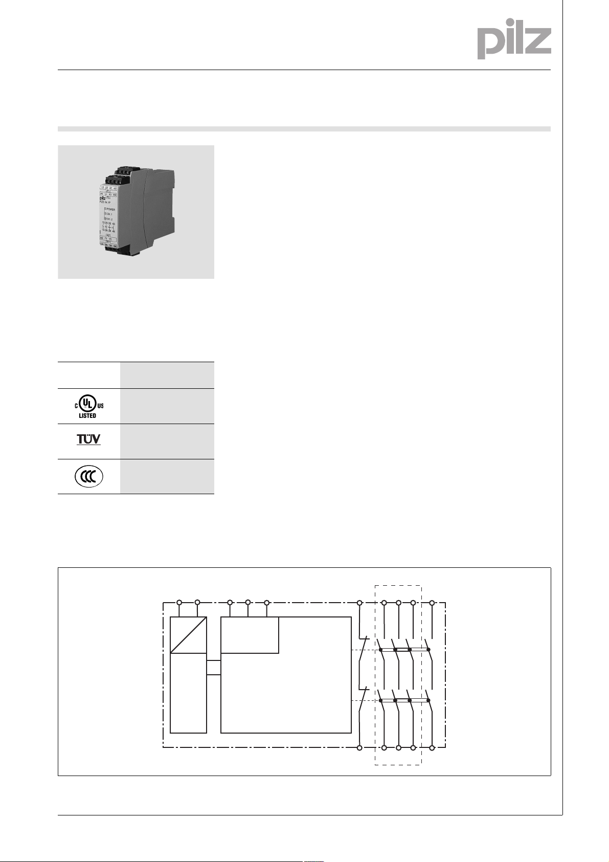
Block diagram
Blockschaltbild
* Safe separation in accordance with EN 60947-1, 6 kV (see unit features)
A1 A2
K1 U K2
=
Input
=
Power
K1
K2
Y2
13 23 33Y1
14 24 34
*
43
44
Pilz GmbH & Co. KG, Felix-Wankel-Straße 2, 73760 Ostfildern, Germany
Telephone: +49 711 3409-0, Telefax: +49 711 3409-133, E-Mail: pilz.gmbh@pilz.de
NSG-D-2-351-2010-01
Page 2
Contact expansion modules
Up to PL e of EN ISO 13849-1
PZE X4.1P
Function description
][Funktionen_Kontakterweiterungen einkanalig
` Single-channel operation: one in-
put circuit affects both output relays
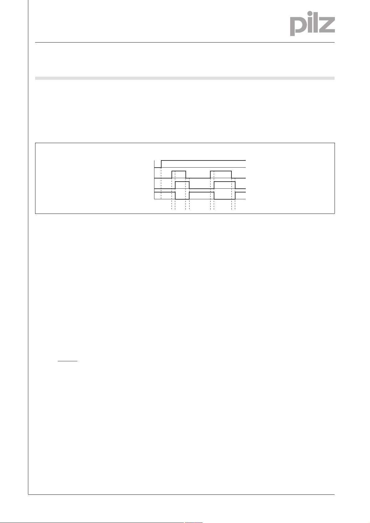
Timing diagram
Output safe
Key
` Power: Supply voltage
` Input: Input circuits K1-U-K2
` Output safe: Safety contacts 13-14,
23-24, 33-34, 43-44
Wiring
][Verdrahtung_Si_unverz
Please note:
` Information given in the “Technical
details” must be followed.
` Outputs 13-14, 23-24, 33-34, 43-44
are safety contacts.
` To prevent contact welding, a fuse
should be connected before the
output contacts (see technical details).
` Calculation of the max. cable runs
in the input circuit:
l
max
R
lmax
=
I
max
Rl / km
= max. overall cable resist-
R
lmax
ance (see technical details)
/km = cable resistance/km
R
l
` Use copper wire that can withstand
60/75 °C.
` Sufficient fuse protection must be
provided on all output contacts with
capacitive and inductive loads.
][Funktionen PZE zweikanalig getaktet
` Dual-channel operation:
– two redundant input circuits af-
fect one output relay
][Zeitdiagramm_in_out_rfk
POWER
Input
Feedback
t1 t1t2 t2
` Feedback: Feedback loop Y1-Y2
` t1: Switch-on delay
: Delay-on de-energisation
` t
2
– Detection of shorts across con-
tacts only possible with pulsed
inputs
Telephone: +49 711 3409-0, Telefax: +49 711 3409-133, E-Mail: pilz.gmbh@pilz.de
NSG-D-2-351-2010-01Pilz GmbH & Co. KG, Felix-Wankel-Straße 2, 73760 Ostfildern, Germany
-2
Page 3
Contact expansion modules
Up to PL e of EN ISO 13849-1
PZE X4.1P
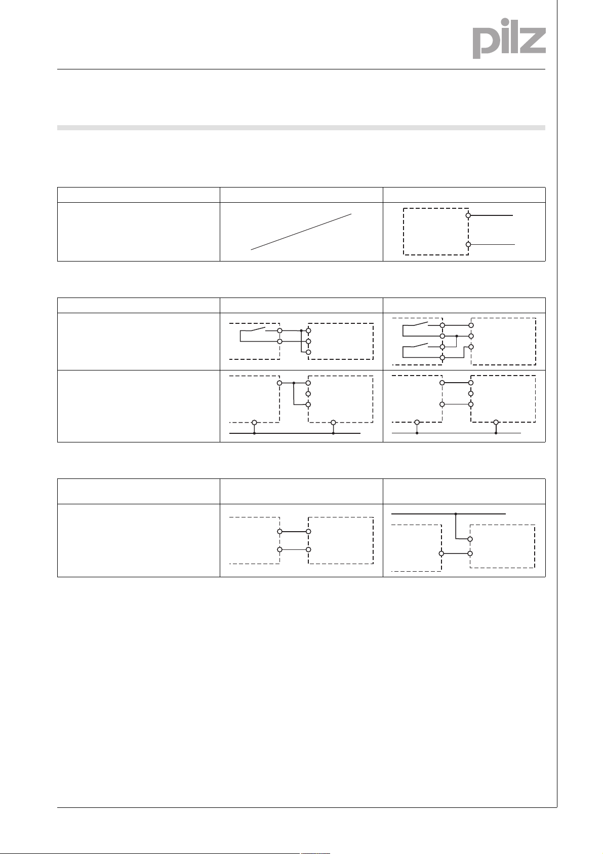
Preparing for operation
Betriebsbereitschaft her stellen
` Supply voltage
Supply voltage AC DC
Only when driven via safety relay with safe-
ty contacts
` Input circuit
Input circuit Single-channel Dual-channel
Base unit:
PNOZ X safety relay
Driven via safety contacts
Base unit:
PNOZelog safety relay, programmable
safety system or PNOZmulti
Driven via safe semiconductor outputs
(24 VDC)
O1
K1
U
K2
K1
U
K2
PZE
A20 V
PZE
L-
O1
O2
A1
A2
K1
U
K2
K1
U
K2
L+
L-
PZE
A20 V
PZE
L-
` Feedback loop
Feedback loop Base unit: PNOZ X
safety relay
Y1, Y2 and Input are inputs on the base
unit; they evaluate the feedback loop
Y1
Y2
Y1
Y2
PZE
Base unit: PNOZelog safety relay, programmable safety system or PNOZmulti
24 V DC
Y1
Input
Y2
PZE
Pilz GmbH & Co. KG, Felix-Wankel-Straße 2, 73760 Ostfildern, Germany
Telephone: +49 711 3409-0, Telefax: +49 711 3409-133, E-Mail: pilz.gmbh@pilz.de
NSG-D-2-351-2010-01
Page 4

Contact expansion modules
Up to PL e of EN ISO 13849-1
PZE X4.1P
Terminal configuration
Klemmenbelegung
43
2313
33
P1
A1 U K1 K2
P2
PNOZ X4.1P
POWER
CH.1
CH.2
43
3323
44
141334
24
P2
A2 Y1 Y2
P1
342414
44
Installation
Montage_PNOZ_X
` The safety relay should be installed
in a control cabinet with a protection type of at least IP54.
` Use the notch on the rear of the unit
to attach it to a DIN rail.
` Ensure the unit is mounted securely
on a vertical DIN rail (35 mm) by using a fixing element (e.g. retaining
bracket or an end angle).
Dimensions
Abmessungen
* with spring-loaded terminals
94 (3.70")
* 101 (3.98")
121 (4.76")
22,5
(0.88")
Telephone: +49 711 3409-0, Telefax: +49 711 3409-133, E-Mail: pilz.gmbh@pilz.de
NSG-D-2-351-2010-01Pilz GmbH & Co. KG, Felix-Wankel-Straße 2, 73760 Ostfildern, Germany
-4
Page 5

Contact expansion modules
Up to PL e of EN ISO 13849-1
PZE X4.1P
Notice
][WICHTIG_PDB_al t
This data sheet is only intended for use
during configuration. For installation
and operation, please refer to the op-
Service life graph
10
AC15: 230 V
erating instructions supplied with the
unit.
1
0.1
E Corriente nominal de servicio (A)
I Corrente di esercizio nominale (A)
NL Nominale bedrijfsstroom (A)
10 100 1000 10000
D Schaltspielzahl x 10
GB Cycles x 10
F Nombre de manuvres x 10
][Technische Daten Kontaktvervielfachung
D Nennbetriebstrom (A)
GB Nominal operating current (A)
F Courant coupé (A)
Technical details
Electrical data
Supply voltage
Supply voltage U
DC 24 V
B
Voltage tolerance -15 %/+10 %
Power consumption at U
DC 2.5 W
B
Residual ripple DC 20 %
Voltage and current at
Input circuit DC: 24.0 V 35.0 mA
Number of output contacts
Safety contacts (S) instantaneous: 4
Utilisation category in accordance with EN 60947-4-1
Safety contacts: AC1 at 240 V I
Safety contacts: DC1 at 24 V I
: 0.01 A , I
min
P
max
: 0.01 A , I
min
P
max
Utilisation category in accordance with EN 60947-5-1
Safety contacts: AC15 at 230 V I
Safety contacts: DC13 at 24 V (6 cycles/min) I
max
max
Contact material AgCuNi + 0.2 µm Au
External contact fuse protection (I
= 1 kA) to EN 60947-5-1
K
Blow-out fuse, quick
Safety contacts: 6 A
Blow-out fuse, slow
Safety contacts: 4 A
Circuit breaker 24 VAC/DC, characteristic B/C
Safety contacts: 4 A
Max. overall cable resistance R
single-channel at U
DC 30 Ohm
B
dual-channel without detect. of shorts across contacts at U
per input circuit
lmax
DC 60 Ohm
B
DC13: 24 V
3
3
max
: 1500 VA
max
: 150 W
: 3.0 A
: 4.0 A
Lebensdauerkurve
: 6.0 A
: 6.0 A
DC1: 24 V
AC1: 230 V
E Número de ciclos x 10
I Numero dei cicli di commutazione x 10
3
NL Aantal schakelingen x 10
3
3
3
Pilz GmbH & Co. KG, Felix-Wankel-Straße 2, 73760 Ostfildern, Germany
Telephone: +49 711 3409-0, Telefax: +49 711 3409-133, E-Mail: pilz.gmbh@pilz.de
NSG-D-2-351-2010-01
Page 6

Contact expansion modules
Up to PL e of EN ISO 13849-1
PZE X4.1P
Safety-related characteristic data
PL in accordance with EN ISO 13849-1 PL e (Cat. 4)
Category in accordance with EN 954-1 Cat. 4
SIL CL in accordance with EN IEC 62061 SIL CL 3
PFH in accordance with EN IEC 62061 2.31E-09
SIL in accordance with IEC 61511 SIL 3
PFD in accordance with IEC 61511 2.03E-06
t
in years 20
M
Times
Switch-on delay
with automatic reset typ. 13 ms
with automatic reset max. 20 ms
with automatic reset after power on typ. 16 ms
with automatic reset after power on max. 30 ms
Delay-on de-energisation
with E-STOP typ. 10 ms
with E-STOP max. 20 ms
with power failure typ. 58 ms
with power failure max. 80 ms
Supply interruption before de-energisation 20 ms
Supply interruption before de-energisation in the input circuit 2.5 ms
Environmental data
EMC EN 60947-5-1, EN 61000-6-2, EN 61000-6-4
Vibration to EN 60068-2-6
Frequency 10 - 55 Hz
Amplitude 0.35 mm
Climatic suitability EN 60068-2-78
Airgap creepage in accordance with EN 60947-1
Pollution degree 2
Overvoltage category III
Rated insulation voltage 250 V
Rated impulse withstand voltage 6.00 kV
Ambient temperature -10 - 55 °C
Storage temperature -40 - 85 °C
Protection type
Mounting (e.g. cabinet) IP54
Housing IP40
Terminals IP20
Mechanical data
Housing material
Housing PPO UL 94 V0
Front ABS UL 94 V0
Cross section of external conductors with screw terminals
1 core flexible 0.25 - 2.50 mm² , 24 - 12 AWG Order no.: 777587
2 core, same cross section, flexible:
with crimp connectors, without insulating sleeve 0.25 - 1.00 mm² , 24 - 16 AWG Order no.: 777587
without crimp connectors or with TWIN crimp connectors 0.20 - 1.50 mm² , 24 - 16 AWG Order no.: 777587
Torque setting with screw terminals 0.50 Nm Order no.: 777587
Cross section of external conductors with spring-loaded terminals: Flexible with/without crimp connectors
Spring-loaded terminals: Terminal points per connection 2 Order no.: 787587
Stripping length 8 mm Order no.: 787587
0.20 - 1.50 mm² , 24 - 16 AWG Order no.: 787587
Telephone: +49 711 3409-0, Telefax: +49 711 3409-133, E-Mail: pilz.gmbh@pilz.de
NSG-D-2-351-2010-01Pilz GmbH & Co. KG, Felix-Wankel-Straße 2, 73760 Ostfildern, Germany
-6
Page 7

Contact expansion modules
Up to PL e of EN ISO 13849-1
PZE X4.1P
Mechanical data
Dimensions
Height 101.0 mm Order no.: 787587
94.0 mm Order no.: 777587
Width 22.5 mm
Depth 121.0 mm
Weight 180 g Order no.: 787587
Technische Daten_Satz No rmen
The standards current on 2008-12 apply.
][Dauerstrom_DC
Conventional thermal current
(A) at UBDC
I
th
1 contact 6.00 A
2 contacts 6.00 A
3 contacts 4.50 A
4 contacts 3.50 A
Bestelldaten
185 g Order no.: 777587
Order reference
Type Features Terminals Order no.
PZE X4.1P C 24 VDC Spring-loaded terminals 787 587
PZE X4.1P 24 VDC Screw terminals 777 587
Pilz GmbH & Co. KG, Felix-Wankel-Straße 2, 73760 Ostfildern, Germany
Telephone: +49 711 3409-0, Telefax: +49 711 3409-133, E-Mail: pilz.gmbh@pilz.de
NSG-D-2-351-2010-01
 Loading...