

Expander modules
Instantaneous
PZE 9
Contact expander module for increasing the number of available contacts
Approvals
PZE 9
Unit features
` Positive-guided relay outputs:
– 8 safety contacts (N/O), instanta-
neous
– 1 auxiliary contact (N/C), instan-
taneous
` LED indicator for:
– Switch status channel 1/2
– Supply voltage
` See order reference for unit types
Unit description
The unit meets the requirements of EN
60204-1 and IEC 60204-1. The contact expander module is used to
increase the number of contacts
available on a base unit. Base units are
all safety relays with feedback loop.
The category that can be achieved in
accordance with EN 954-1 depends
on the category of the base unit. The
contact expander module may not exceed this.
Safety features
The unit meets the following safety requirements:
` The contact expander module ex-
pands an existing circuit. As the
output relays are monitored via the
base unit's feedback loop, the safety functions on the existing circuit
are transferred to the contact expander module.
` The safety function remains effecti-
ve in the case of a component failure.
` Earth fault in the feedback loop:
Detected, depending on the base
unit that is used.
` Earth fault in the input circuit:
The output relays de-energise and
the safety contacts open.
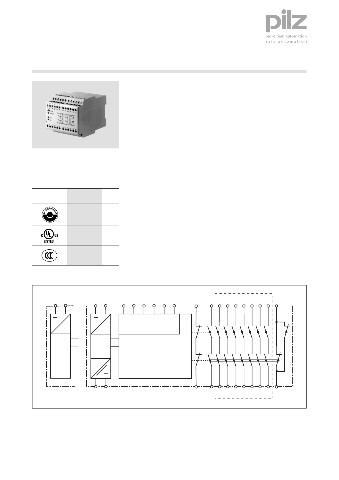
Block diagram
UB = 24 V AC/DC UB = 24 V AC/DC
A1 A2
~
B1 B2 13 23 33
~
=
Power
Power
=
A1 A2
U
B
* Galvanic isolation at U
B
AC
K1 U1 K2 U2 Y3 Y4
=
~
= 100 - 240 V AC/DC
Input
K1
K2
Y1
Y2
14 24 34
43
53 63 73 83 91
44
54 64 74 84 92
*
Pilz GmbH & Co. KG, Sichere Automation, Felix-Wankel-Straße 2, 73760 Ostfildern, Germany
Telephone: +49 711 3409-0, Telefax: +49 711 3409-133, E-Mail: pilz.gmbh@pilz.de
NSG-D-2-093-11/04

Expander modules
Instantaneous
PZE 9
Function description ` Single-channel operation: one in-
put circuit affects both output relays
` Dual-channel operation:
Timing diagram
POWER
Input
Output safe
Output aux.
Feedback
t1 t1t2 t2
Key
` Power: Supply voltage
` Input: Input circuits U1, U2, K1, K2,
Y3, Y4
` Output safe: Safety contacts 13-14,
23-24, 33-34, 43-44, 53-54, 63-64,
73-74, 83-84
` Output aux: Auxiliary contacts 91-
92
Wiring
– two redundant input circuits af-
fect one output relay
– Detection of shorts across con-
tacts is also possible
` Feedback: Feedback loop Y1-Y2
: Switch-on delay
` t
1
Please note:
` Information given in the “Technical
details” must be followed.
` Outputs 13-14, 23-24, 33-34, 43-
44, 53-54, 63-64, 73-74, 83-84 are
safety contacts, output 91-92 is an
auxiliary contact (e.g. for display).
` To prevent contact welding, a fuse
should be connected before the
output contacts (see technical details).
` Calculation of the max. cable runs
in the input circuit:
l
max
R
lmax
=
I
max
Rl / km
= max. overall cable resi-
R
lmax
stance (see technical details)
/ km = cable resistance/km
R
l
` Use copper wire that can withstand
60/75 °C.
` Sufficient fuse protection must be
provided on all output contacts with
capacitive and inductive loads.
Telephone: +49 711 3409-0, Telefax: +49 711 3409-133, E-Mail: pilz.gmbh@pilz.de
NSG-D-2-093-11/04Pilz GmbH & Co. KG, Sichere Automation, Felix-Wankel-Straße 2, 73760 Ostfildern, Germany
-2
Expander modules
Instantaneous
PZE 9
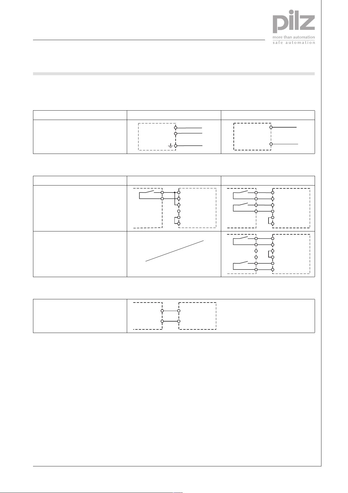
Preparing for operation
` Supply voltage
Supply voltage AC DC
A1
A2
L1
N
PE
` Input circuit
Input circuit Single-channel Dual-channel
without detection of shorts across
contacts
K1
U1
K2
U2
Y3
Y4
PZE
with detection of shorts across contacts
` Feedback loop
A1
A2
K1
U1
K2
U2
Y3
Y4
K1
U1
K2
U2
Y3
Y4
L+
L-
PZE
PZE
Y1 and Y2 are feedback loop inputs on
the base unit
Pilz GmbH & Co. KG, Sichere Automation, Felix-Wankel-Straße 2, 73760 Ostfildern, Germany
Telephone: +49 711 3409-0, Telefax: +49 711 3409-133, E-Mail: pilz.gmbh@pilz.de
Y1
Y2
Y1
Y2
PZE
NSG-D-2-093-11/04

Expander modules
Instantaneous
PZE 9
Terminal configuration
UB = 24 VDC
U1
K1 K2
A1 K1
A3 14
PZE 9
POWER
CH.1
CH.2
U2 Y3
13
34 44 8464 74
24
Y4
4323 33 7353 63
131423243334434453546364737483849192Y1
54
UB = 24 V, 42 V, 48 V, 110 – 120 V, 230
– 240 VAC
U1
K1 K2
A1 K1
PZE 9
POWER
13
U2 Y3
Y4
4323 33 7353 63
131423243334434453546364737483849192Y1
83 91
Y292A2
83 91
Y1
Y2
Y1
Installation
` The safety relay should be installed
in a control cabinet with a protection type of at least IP54.
` Use the notch on the rear of the unit
to attach it to a DIN rail.
` Ensure the unit is mounted securely
on a vertical DIN rail (35 mm) by
using a fixing element (e.g. retaining
bracket or an end angle).
Dimensions
CH.1
CH.2
14
75 (2.95")
87 (3.42")
34 44 8464 74
24
54
121 (4.76")
Y2
Y292A2
90 (3.54")
Telephone: +49 711 3409-0, Telefax: +49 711 3409-133, E-Mail: pilz.gmbh@pilz.de
NSG-D-2-093-11/04Pilz GmbH & Co. KG, Sichere Automation, Felix-Wankel-Straße 2, 73760 Ostfildern, Germany
-4

Expander modules
Instantaneous
PZE 9
Notice
Service life graph
This data sheet is only intended for use
during configuration. For installation
and operation, please refer to the ope-
10
AC1: 230 V
rating instructions supplied with the
unit.
DC13: 24 V
1
D Nennbetriebstrom (A)
GB Nominal operating current (A)
F Courant coupé (A)
Technical details
Electrical data
Supply voltage UB AC
Supply voltage U
B
DC
Voltage tolerance -15 % / +10 %
Power consumption at U
Power consumption at U
B
B
AC
DC
Frequency range AC 50 - 60 Hz
Residual ripple DC 160 %
Voltage and current at
Input circuit: 24 VDC 40 mA
Output contacts in accordance with EN 954-1 Safety contacts (N/O): 8
Utilisation category in accordance with EN 60947-4-1
Safety contacts:
AC1: 240 V
AC1: 400 V
DC1: 24 V
Utilisation category in accordance with EN 60947-5-1
AC15: 230 V
DC13 (6 cycles/min): 24 V
Utilisation category in accordance with EN 60947-4-1
Auxiliary contacts
AC1: 240 V
DC1: 24 V
Utilisation category in accordance with EN 60947-5-1
AC15: 230 V
DC13 (6 cycles/min): 24 V
Contact material AgSnO
External contact fuse protection (EN 60947-5-1)
Safety contacts
Blow-out fuse, quick
Blow-out fuse, slow
Circuit breaker
0.1
E Corriente nominal de servicio (A)
I Corrente di esercizio nominale (A)
NL Nominale bedrijfsstroom (A)
10 100 1000 10000
D Schaltspielzahl x 10
GB Cycles x 10
F Nombre de manvres x 10
24 V, 42 V, 48 V, 110 – 120 V, 230 - 240 V
24 V
7 VA
3.5 W
Auxiliary contacts (N/C): 1
I
: 0.01 A, I
min
P
: 2000 VA
max
I
: 0.01 A, I
min
P
: 2000 VA
max
I
: 0.01 A, I
min
P
: 200 W
max
: 5 A
I
max
I
: 7 A
max
I
: 0.01 A, I
min
P
: 500 VA
max
I
: 0.01 A, I
min
P
: 50 VA
max
: 2 A
I
max
I
: 2 A
max
10 A
6 A
6 A, 24 VAC/DC, characteristic B/C
3
3
: 8 A
max
: 5 A
max
: 8 A
max
: 2 A
max
: 2 A
max
+ 0.2 µm Au
2
DC1: 24 V
AC1: 400 V
AC15: 230 V
E Número de ciclos x 10
I Numero dei cicli di commutazione x 10
3
NL Aantal schakelingen x 10
3
3
3
Pilz GmbH & Co. KG, Sichere Automation, Felix-Wankel-Straße 2, 73760 Ostfildern, Germany
Telephone: +49 711 3409-0, Telefax: +49 711 3409-133, E-Mail: pilz.gmbh@pilz.de
NSG-D-2-093-11/04

Expander modules
Instantaneous
PZE 9
Electrical data
External contact fuse protection (EN 60947-5-1)
Auxiliary contacts
Blow-out fuse, quick
Blow-out fuse, slow
Circuit breaker
Max. overall cable resistance R
reset circuits
Single-channel at U
Single-channel at U
Dual-channel without detect. of shorts across contacts at U
Dual-channel without detect. of shorts across contacts at U
Dual-channel with detect. of shorts across contacts at U
Dual-channel with detect. of shorts across contacts at U
Times
Switch-on delay
After closing the input circuits typ.
After closing the input circuits max.
After power on typ.
Power on max.
Delay-on de-energisation
After opening the input circuits typ.
After opening the input circuits max.
with power failure typ.
with power failure max.
Supply interruption before de-energisation 20 ms Order no.: 774150
Environmental data
EMC EN 60947-5-1, EN 61000-6-2
Vibration in accordance with EN 60068-2-6
Frequency
Amplitude
Climatic suitability EN 60068-2-78
Airgap creepage EN 60947-1
Ambient temperature -10 - 55 °C
Storage temperature -40 - 85 °C
Protection type
Mounting (e.g. cabinet)
Housing
Terminals
Mechanical data
Housing material
Housing
Front
Max. cross section of external conductors with screw terminals
1 core flexible
2 core, same cross section, flexible:
with crimp connectors, without insulating sleeve
without crimp connectors or with TWIN crimp connectors
Torque setting with screw terminals 0.6 Nm
Dimensions (H x W x D)
with screw terminals 87 mm x 90 mm x 121 mm
Weight 450 g Order no.: 774150
B
B
DC
AC
Input circuits,
lmax
B
B
DC
AC
4 A
2 A
2 A, 24 VAC/DC, characteristic B/C
50 Ohm Order no.: 774150
80 Ohm Order no.: 777140, 774141, 777142, 777143, 774148
100 Ohm Order no.: 774150
DC
B
160 Ohm Order No.: 777140, 774141, 777142, 777143, 774148
AC
B
5 Ohm Order no.: 774150
10 Ohm Order no.: 777140, 774141, 777142, 777143, 774148
30 ms Order no.: 774150
25 ms Order no.: 777140, 774141, 777142, 777143, 774148
40 ms
30 ms Order no.: 774150
50 ms Order no.: 777140, 774141, 777142, 777143, 774148
40 ms Order no.: 774150
70 ms Order no.: 777140, 774141, 777142, 777143, 774148
20 ms
30 ms
110 ms Order no.: 774150
220 ms Order no.: 777140, 774141, 777142, 777143, 774148
150 ms Order no.: 774150
300 ms Order no.: 777140, 774141, 777142, 777143, 774148
150 ms Order no.: 777140, 774141, 777142, 777143, 774148
10 - 55 Hz
0.35 mm
IP54
IP40
IP20
PPO UL 94 V0
ABS UL 94 V0
0.20 – 4.00 mm
0.20 – 2.50 mm
0.20 – 2.50 mm
600 g Order no.: 777140, 774141, 777142, 777143, 774148
2
2
2
The standards current on 03/01 apply.
Telephone: +49 711 3409-0, Telefax: +49 711 3409-133, E-Mail: pilz.gmbh@pilz.de
NSG-D-2-093-11/04Pilz GmbH & Co. KG, Sichere Automation, Felix-Wankel-Straße 2, 73760 Ostfildern, Germany
-6

Expander modules
Instantaneous
PZE 9
Max. continuous current
Number of contacts
1 8.0 A Order no.: 774150 8.0 A Order no.: 774140, 774141, 774142, 774143,
2 8.0 A Order no.: 774150 8.0 A Order no.: 774140, 774141, 774142, 774143,
3 8.0 A Order no.: 774150 7.4 A Order no.: 774140, 774141, 774142, 774143,
4 7.1 A Order no.: 774150 6.4 A Order no.: 774140, 774141, 774142, 774143,
5 6.3 A Order no.: 774150 5.7 A Order no.: 774140, 774141, 774142, 774143,
6 5.8 A Order no.: 774150 5.2 A Order no.: 774140, 774141, 774142, 774143,
7 5.4 A Order no.: 774150 4.8 A Order no.: 774140, 774141, 774142, 774143,
8 5.0 A Order no.: 774150 4.5 A Order no.: 774140, 774141, 774142, 774143,
Order reference
Type Features Terminals Order no.
PZE 9 24 VAC Screw terminals 774 140
PZE 9 42 VAC Screw terminals 774 141
PZE 9 48 VAC Screw terminals 774 142
PZE 9 110 - 120 VAC Screw terminals 774 143
PZE 9 230 - 240 VAC Screw terminals 774 148
PZE 9 24 VDC Screw terminals 774 150
(A) at UBDC I
I
max
(A) at UBAC I
max
774148
774148
774148
774148
774148
774148
774148
774148
(A) at UBAC, DC:
max
AC1 = 400 V
5.0 A
5.0 A
5.0 A
5.0 A
5.0 A
5.0 A
4.8 A
4.5 A
Pilz GmbH & Co. KG, Sichere Automation, Felix-Wankel-Straße 2, 73760 Ostfildern, Germany
Telephone: +49 711 3409-0, Telefax: +49 711 3409-133, E-Mail: pilz.gmbh@pilz.de
NSG-D-2-093-11/04
 Loading...