

Pilz PX 30, PX 120 Operating Manual

Artisan Technology Group is your source for quality
new and certied-used/pre-owned equipment
• FAST SHIPPING AND
DELIVERY
• TENS OF THOUSANDS OF
IN-STOCK ITEMS
• EQUIPMENT DEMOS
• HUNDREDS OF
MANUFACTURERS
SUPPORTED
• LEASING/MONTHLY
RENTALS
• ITAR CERTIFIED
SECURE ASSET SOLUTIONS
SERVICE CENTER REPAIRS
Experienced engineers and technicians on staff
at our full-service, in-house repair center
WE BUY USED EQUIPMENT
Sell your excess, underutilized, and idle used equipment
We also offer credit for buy-backs and trade-ins
www.artisantg.com/WeBuyEquipment
REMOTE INSPECTION
Remotely inspect equipment before purchasing with
our interactive website at www.instraview.com
LOOKING FOR MORE INFORMATION?
Visit us on the web at www.artisantg.com for more
information on price quotations, drivers, technical
specications, manuals, and documentation
Contact us: (888) 88-SOURCE | sales@artisantg.com | www.artisantg.com
SM
View
Instra
Displays and Operator Terminals
PX 30 and PX 120
Operating Manual
Item No. 17 940
Pilz GmbH & Co.
Felix-Wankel-Straße 2, 73760 Ostfildern, Deutschland
Telefon (07 11) 34 09-0, Telefax (07 11) 34 09-1 33
AUS
BR
DK
A
B
L
CH
D
E
...
www
MEX
J
IRL
I
GB
FIN
F
NL
P
PRC
ROK
S
SGP
USA
Pilz GmbH & Co.
Felix-Wankel-Straße 2, 73760 Ostfildern, Germany
Telephone +49 (7 11) 34 09-0, Telefax +49 (7 11) 34 09-133
Pilz Ges.m.b.H.
Modecenterstraße 14
1030 Wien
Austria
Telephone (01) 7 98 6263-0
Telefax (01) 7 9862 64
E-Mail: pilz@pilz.at
Pilz Australia
Industrial Automation LP.
9/475 Blackburn Road
Mt. Waverley, Melbourne VIC 3149
Australia
Telephone (03) 95 44 6300
Telefax (03) 95 4463 11
E-Mail: safety@pilz.com.au
Pilz Belgium
BC Building
lndustriezone lII
lndustrielaan 4
9320 Erembodegem
Belgium
Telephone (0 53) 8366 70
Telefax (0 53) 8389 58
E-Mail: info@pilz.be
Pilz do Brasil Sistemas Eletrônicos
Industriais Ltda.
Rua Ártico, 123 - Jd. do Mar
09726-300
São Bernardo do Campo - SP
Brazil
Telephone (11) 43 37-12 41
Telefax (11) 43 37-1242
E-Mail: pilz@pilzbr.com.br
Pilz lndustrieelektronik GmbH
Gewerbepark Hintermättli
Postfach 6
5506 Mägenwil
Switzerland
Telephone (0 62) 8 8979 30
Telefax (0 62) 889 79 40
E-Mail: pilz@pilz.ch
Headquarters:
Pilz GmbH & Co.
Felix-Wankel-Straße 2
73760 Ostfildern
Germany
Telephone (07 11) 34 09-0
Telefax (07 11) 3409-1 33
E-Mail: pilz.gmbh@pilz.de
Pilz Skandinavien KS
Ellegaardvej 25 L
6400 Sonderborg
Denmark
Telephone 74 4363 32
Telefax 74 4363 42
E-Mail: pilz@pilz.dk
Pilz lndustrieelektronik S.L.
Edificio Tilma
Avda. Sant Julià 1
08400 Granollers
Spain
Telephone (93) 8 49 7433
Telefax (93) 8 4975 44
E-Mail: central@pilzspain.com
Pilz France Electronic
1, rue Jacob Mayer
BP 12
67037 Strasbourg Cedex
France
Telephone 03 8810 40 00
Telefax 03
8810 80 00
E-Mail: siege@pilz-france.fr
Pilz Skandinavien KS
Pakilantie 61
00660 Helsinki
Finland
Telephone (09) 27 09 3700
Telefax (09) 27 0937 09
E-Mail: pilz.sk@kolumbus.fi
Pilz Automation Technology
Willow House, Medlicott Close
Oakley Hay Business Park
Corby
Northants NN18 9NF
United Kingdom
Telephone (0 15 36) 46 0766
Telefax (0 15 36) 4608 66
E-Mail: sales@pilz.co.uk
Pilz ltalia Srl
Via Meda 2/A
22060 Novedrate (CO)
Italy
Telephone (0
31) 78 9511
Telefax (0 31) 7895 55
E-Mail: info@pilz.it
Pilz Ireland Industrial Automation
Cork Business and Technology Park
Model Farm Road
Cork
Ireland
Telephone (0 21) 4 3465 35
Telefax (0 21) 480 4994
E-Mail: sales@pilz.ie
Pilz Japan Co., Ltd.
Three One Building 701
3-20-5 Shin-Yokohama
Kohoku-ku
Yokohama 222-0033
Japan
Telephone (0 45) 4 71-2281
Telefax (0 45) 471-22 83
E-Mail: pilz@pilz.co.jp
Pilz de Mexico S. de R.L. de C.V.
Av. San Ignacio 1079
Col. Jardines de San Ignacio
C.P. 45000
Guadalajara, Jalisco
Mexico
Telephone (0 13) 1 2216 81
Telefax (0 13) 647 8185
E-Mail: pilz_msolis@infosel.net.mx
Pilz Nederland
Postbus 186
4130 ED Vianen
Netherlands
Telephone (03 47) 3204 77
Telefax (03 47) 3204 85
E-Mail: info@pilz.nl
Pilz Industrieelektronik S.L.
Apartado 2028
2706-909 Colares
Portugal
Telephone (21) 9 2891 09
Telefax (21) 9 2891 13
E-Mail: pilz@esoterica.pt
Pilz China Representative Office
Flat F9/F Huijing Building
134 Siyou Xin Malu
Dongshan District
Guangzhou 510600
China
Telephone (0 20) 8737 16 18
Telefax (0 20) 8737 3555
E-Mail:
pilzchn@public.guangzhou.gd.cn
Pilz Korea Liaison Office
102-1402 Ilsung apt
767, Kyomun-Dong, Kuri-Si
Kyungki-Do 417-715
Korea
Telephone (31) 5 5412 80
Telefax (31) 5 5412 80
E-Mail: pilzkr@hotmail.com
Pilz Skandinavien KS
Energigatan 10 B
43437 Kungsbacka
Sweden
Telephone (03 00) 1 3990
Telefax (03 00) 307 40
E-Mail: pilz@tripnet.se
Pilz Industrial Automation Pte Ltd.
61, Kaki Bukit Ave 1, #05-01
Shun Li Industrial Park
Singapore 417943
Singapore
Telephone 8 4444 40
Telefax 8 4444 41
E-Mail: sales@pilz.com.sg
Pilz LP
7150 Commerce Boulevard
Canton
Michigan 48187
USA
Telephone (7 34) 354-02 72
Telefax (7 34) 354-33 55
E-Mail: info@pilzusa.com
In many countries we are represented by sales partners. Please refer to our
Homepage for further details or contact our headquarters.
Internet enquiries and orders: www.pilz.com
www.pilz.com
17 940-01/02 Printed in Germany
Artisan Technology Group - Quality Instrumentation ... Guaranteed | (888) 88-SOURCE | www.artisantg.com

All rights reserved by Pilz GmbH & Co. Copying permitted for internal use only.
In the interest of continual technical advancement we reserve the right to amend
technical details without prior notice. No responsibility accepted for errors or omissions.
We are grateful for any feedback on the contents of this manual.
The names of products, goods and technologies are trademarks of the companies
concerned.
III, 01/02
Artisan Technology Group - Quality Instrumentation ... Guaranteed | (888) 88-SOURCE | www.artisantg.com
PX 30 and PX 120 Operating Manual
1
Safety Regulations 1.1
General Safety Regulations 1-1
Unit-Specific Safety Regulations 1-1
System Description PX 30 and PX 120 2-1
Operation 2-1
Features 2-3
Flash-EPROM Memory 2-3
Dimmer Function 2-4
Hardware 2-4
PLC Connections 2-5
Driving the Display 3-1
Handshake Function 3-1
Operating Modes in Display Mode 3-2
Parallel Drive through a PLC's I/O-Level
Display Mode 3-3
Coding 3-3
Text Display with 24 Inputs (PX 120) 3-5
Text Display with 16 Inputs
(PX 30 or PX 120 in 16-Input Mode) 3-12
Parallel Drive through a PLC's I/O-Level
Monitor Mode 3-20
Function and Layout of Inputs 3-20
Serial Drive
Display Mode 3-22
Data Communication Protocol 3-22
PX 30/PX 120 Response 3-23
Operating Modes 3-23
Examples for Serial Drive in Display Mode 3-26
Contents
Artisan Technology Group - Quality Instrumentation ... Guaranteed | (888) 88-SOURCE | www.artisantg.com

2
PX 30 and PX 120 Operating Manual
Contents
Contents
Serial Drive
Monitor Mode 3-31
Communication Protocol 3-31
Communication Protocol for individual data 3-31
Communication Protocol for packaged data 3-32
Text in Display Mode 4-1
Text Memory 4-1
Creating Text 4-1
Character Set 4-1
Control Characters (ESCAPE Sequences) 4-1
Layout 4-2
Clear Display 4-2
Scrolling Background Text 4-3
Variables in Display Mode 5-1
Basics 5-1
Variable Layout 5-1
Text Characters within Variables 5-2
Overlapping Variables 5-2
Left / Right Justification 5-2
Leading Zeros 5-2
Inserting a Cursor or Question Mark 5-3
Variables in Background Text 5-3
Configuration 6-1
Artisan Technology Group - Quality Instrumentation ... Guaranteed | (888) 88-SOURCE | www.artisantg.com

PX 30 and PX 120 Operating Manual
3
Appendix 7-1
Technical Details 7-1
Connector Pin Assignment (V24) 7-1
Dimensions 7-2
PX 30 Text Display 7-2
PX 120 Text Display 7-2
Control Codes 7-3
System Messages 7-4
Error Codes 7-4
Error Messages 7-5
Procedure after Power-up 7-5
Networking Capabilities 7-6
Character Sets 7-7
IBM Character Set 7-7
Cyrillic Character Set 7-8
V24 Connection Cable - Pin Layout 7-9
Artisan Technology Group - Quality Instrumentation ... Guaranteed | (888) 88-SOURCE | www.artisantg.com

4
PX 30 and PX 120 Operating Manual
Contents
Notes
Artisan Technology Group - Quality Instrumentation ... Guaranteed | (888) 88-SOURCE | www.artisantg.com

1-1
PX 30 and PX 120 Operating Manual
Safety Regulations
General Safety Regulations
• Electrical connections must be made by a qualified electrical engineer
who is familiar with the operating manual and the valid regulations for
safety in the workplace. VDE and local regulations must be observed, in
particular with regard to safety.
• It is important to keep within the permitted operating temperature range.
• Do not open the unit, otherwise all warranty becomes void. Units
requiring repair must be returned to Pilz.
• The correct function of the unit is guaranteed only for the operating
modes specified in the operating manual. Incorrect connections may
damage or destroy the unit or machinery.
Unit-Specific Safety Regulations
You must comply with the following safety regulations in order to ensure
the correct operation of your unit:
• When selecting where to install your display, please remember to keep
as large a distance as possible between the unit and any
electromagnetic fields. This is especially important when frequency
converters are nearby. We also recommend you use a bulkhead to
separate the display from any source of interference.
• Inductive components built into the surrounding area (eg. contactor, relay
and solenoid valve coils), must be wired with an RC-network, especially if
they are fed from the same source.
• Data and power lines should be installed separately to avoid capacitive
and inductive transmission (recommended minimum distance = 10 cm/
3.94")!
• To avoid the build-up of heat, a distance of 10 cm/3.94" should be main-
tained all round the unit.
Artisan Technology Group - Quality Instrumentation ... Guaranteed | (888) 88-SOURCE | www.artisantg.com

PX 30 and PX 120 Operating Manual1-2
Safety Regulations
• Interference voltages accessing the unit via supply and signal lines, and
electrostatic voltages passed on through contact, are diverted to the
earth point (spade terminal on the rear of the unit).
Connect the earth point ( ) to the earth conductor PE using as short a
copper conductor as possible (> 6 mm2 csa).
• The earth conductor should be connected to the terminal marked on
the supply voltage connector (1.5 mm2 diameter).
• Before applying voltage always check that the voltage information given
on the unit matches your supply.
• Shielded, twisted pair cable must be used for connections to the inter-
faces.
• Always use metallic or metallised synthetic connectors with the connec-
tion cable.
• We recommend that the shielded connection on the network cable
between two subscribers is connected on both sides. This will require
sufficient potential equalisation between the earth conductor potentials at
each subscriber. The most effective method of screening is to connect
the braided screening to a potential equalisation rail over a wide surface
area. Both the unscreened wires at the cable ends and the shielded
connections should be kept as short as possible.
Please note: On the display system, the cable screening is connected
directly (galvanically) to the housing.
If the potential equalisation is insufficient, the screening on the
connection and/or programming cable may only be connected on one
side of the connector housing.
Please note: The screening on the programming cable supplied by Pilz
is connected on one side (PX-side) of the connector housing.
• Please ensure that the mounting screws on the connector are firmly
attached.
Artisan Technology Group - Quality Instrumentation ... Guaranteed | (888) 88-SOURCE | www.artisantg.com

1-3
PX 30 and PX 120 Operating Manual
• The power supply for the text display must be designed for a peak
switching current of 15 x IN.
• Connections / units must not be removed or modifed during operation.
Always ensure that the supply is switched off.
• Do not change the text memory while power is applied to the unit.
Before installation you should also check the safety requirements laid
down by the PLC manufacturer.
Artisan Technology Group - Quality Instrumentation ... Guaranteed | (888) 88-SOURCE | www.artisantg.com

PX 30 and PX 120 Operating Manual1-4
Safety Regulations
Notes
Artisan Technology Group - Quality Instrumentation ... Guaranteed | (888) 88-SOURCE | www.artisantg.com

PX 30 and PX 120 Operating Manual
2-1
Operation
The PX 30 and PX 120 can be driven in parallel through a PLC's I/O-level or in serial
through the V24 interface of a PLC or PC.
The PX 30 has 16 inputs and the PX 120 has 24 inputs available for parallel drive, plus
one output.
The PX 120 can be configured to use just 16 inputs (instead of 24) for communicating data
and commands. The configuration of "16-input mode" is explained in the chapter entitled
"Configuration" from page 6-1 onwards.
Both units (PX 30 and PX 120) can be operated as either a:
• Text Display or
• Text Monitor.
You can select the mode (display or monitor mode) in which the display unit will operate
via input E15 on the PX 30 and input E23 on the PX 120:
• E15 or E23 high = monitor mode
• E15 or E23 low = display mode
In display mode, the PLC selects the text stored in the memory through its text number,
and variable values sent from the PLC are inserted in the displayed text.
In monitor mode, texts are sent from the PLC as characters from the IBM character set
(extended ASCII character set). Control commands such as cursor positioning and the
allocation of attributes, etc. must be sent as part of the message.
The features of the two different display modes are described in the table below. The two
right-hand columns tell you where you can find additional information on the individual
features.
Operating in Display Mode
Feature Refer to Chapter / From
Section Page
Both parallel and serial drive is possible:
- parallel drive via 24 inputs (PX120) Parallel drive via a 3-5
PLC's I/O level display mode:
Text display with
24 inputs
- parallel drive via 16 inputs (PX 30 or PX 120 in Text display with 3-12
16-input mode) 16 inputs
- serial drive Serial drive 3-22
display mode
System Description PX 30 and PX 120
Artisan Technology Group - Quality Instrumentation ... Guaranteed | (888) 88-SOURCE | www.artisantg.com

2-2
System Description PX 30 and PX 120
PX 30 and PX 120 Operating Manual
Operating in Display Mode (Ctd.)
Feature Refer to Chapter / From
Section Page
Texts stored in the text memory are selected (Text in general:) Text 4-1
and displayed in display mode
Variables (eg. true and set values) can be inserted (Variables in general:) 5-1
into the text. These variables are selected Variables in display
via their number and can be displayed with certainmode
attributes (eg. flashing, right justification).
Control characters and text masks edited in the text
enable you to allocate attributes and position the
cursor.
Additional display functions (eg. scrolling and Driving the Display 3-1
segment test) are available via control commands
from the PLC.
Configuration instructions stored in the text memory Configuration 6-1
enable the display to adapt to certain user
requirements (eg. scroll function, coding and the
number of inputs used).
Several displays can be networked through a Appendix / Networking 7-6
V24 - RS 485 interface adapter. Capabilities
Operating in Monitor Mode
Feature Refer to Chapter / From
Section Page
Both parallel and serial drive is possible:
- parallel drive via 24 inputs (PX 120) Parallel drive via a 3-20
- parallel drive via 16 inputs (PX 30 or PX 120 in PLC's I/O level -
16-input mode monitor mode
- serial drive Serial drive 3-31
monitor mode
PLC sends texts as IBM/ASCII characters.
These are displayed at the cursor position.
Additional display functions (eg. scrolling and
segment test) are available via control commands
from the PLC.
Artisan Technology Group - Quality Instrumentation ... Guaranteed | (888) 88-SOURCE | www.artisantg.com

PX 30 and PX 120 Operating Manual
2-3
Features
The following features have been incorporated into the units:
• IBM character set
• Flash-EPROM as text memory, programmable within the PX-unit.
• Either parallel (via I/O-level) or serial (via V24) drive
• Optimum speed
• Shallow modular depth
• Automatic brightness control on the display (dimmer function)
• Extended scrolling options
• Networkable
• Status display
The main difference between the PX 30 and PX 120 is their display format and the
number of inputs they have available:
Unit Display Format Number of PX Inputs
PX 30 2 lines of 20 characters; 5 mm character height; 16
5 x 7 dot matrix
PX 120 2 lines of 40 characters; 9 mm character height; 24
5 x 12 dot matrix
Data transmission varies depending on the number of inputs. These differences are
explained in Chapter 2.
Flash-EPROM Memory
Flash-EPROMs are used as text memory. These are currently the quickest memory chips
available for text displays. Just like EEPROM-chips, they are programmed and cleared
electrically. Flash-EPROMs can be programmed directly inside the PX-unit, combining
the data security of an EPROM with the flexibility of a RAM. The ability of the EEPROM to
clear byte by byte is not availabe on the Flash-EPROM, but this facility is not required on
text displays.
The simplest way to create text is to use an IBM-compatible PC with ADIT DOS (version
4.0 and above). This software has been specially designed for organising data transmission on these PX-units. Texts, attributes for text and variables (eg. flashing representation) and text masks for variables are all edited through dialogue.
The Flash-EPROM is programmed directly inside the PX-unit. When the text display is
ready for operation, (ie. 24 V is supplied), just connect it up to a PC through its serial
interface and the text memory can be programmed quite simply using the ADIT DOS Text
Editor (under MS DOS).
The programming of the Flash-EPROM in the PX-unit via the serial interface (V24) is not
described in this manual. For further details please refer to the ADIT DOS Manual.
Artisan Technology Group - Quality Instrumentation ... Guaranteed | (888) 88-SOURCE | www.artisantg.com

2-4
System Description PX 30 and PX 120
PX 30 and PX 120 Operating Manual
Dimmer Function
A sensor judges the brightness at the front of the unit and adapts the brightness of the
display accordingly.
This dimmer function is activated by setting a jumper (1) on the rear of the unit (below the
Flash-EPROM).
The jumper is not inserted ex-works, so the dimmer is switched off. In this case the
display will operate at a constant maximum brightness.
When the dimmer is activated (jumper inserted), optimum standard brightness is achieved
as follows:
Adjust the dimmer setting (2) with a screwdriver until maximum brightness is achieved
under typical light conditions.
Start from the right stopper and turn anti-clockwise until the display begins to darken.
Then carefully turn it clockwise again until it lightens.
Hardware
Both units have:
• Fluorescent Display; 2 lines
• 24 V inputs (16 inputs on the PX 30, 24 inputs on the PX 120)
• One 24 V output (handshake output "HS")
• Serial Interface (V24, 9-pin)
• Automatic brightness control (dimmer function)
• 32 KByte Flash-EPROM cartridge; 64 KByte available as an option
• Ability to program the Flash-EPROM inside the unit.
MEMORY
DISPLAY
RS 232
(2) (1)
Artisan Technology Group - Quality Instrumentation ... Guaranteed | (888) 88-SOURCE | www.artisantg.com
PX 30 and PX 120 Operating Manual
2-5
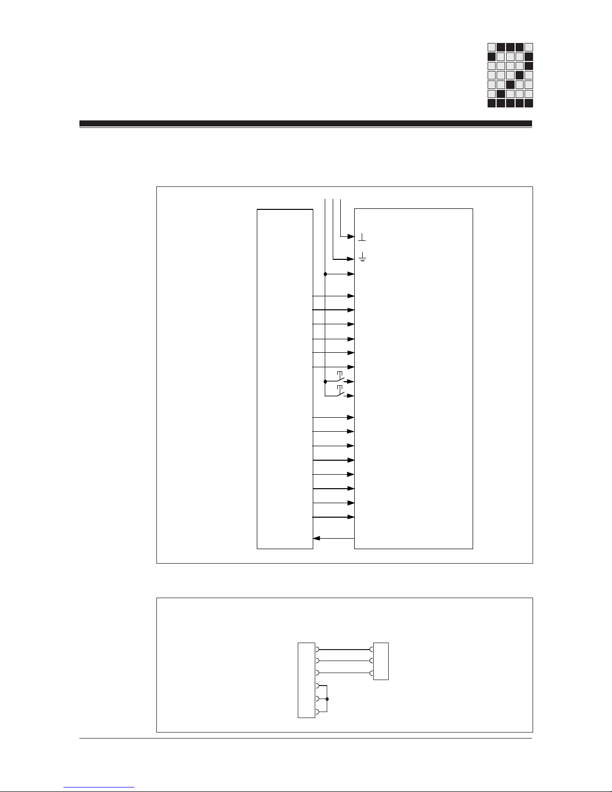
PLC PX 30 / PX 120
Parallel drive via the I/O-level:
Serial drive via the V24 Interface:
HS HANDSHAKE
E 7/E 15
E 6/E 14
E 5/E 13
E 4/E 12
E 3/E 11
E 2/E 10
E 1/E 9
E 0/E 8
E 15/E 23 Display Mode
E 14/E 22 Enable
E 13/E 21 Operating Mode
E 12/E 20 Special Mode
E 11/E 19 End of Cycle
E 10/E 18 Start of Cycle
E 9/E 17 Scroll Up
E 8/E 16 Scroll Down
+24 V=
PLC Connections
O/P x.h
O/P x.g
O/P x.f
O/P x.e
O/P x.d
O/P x.c
O/P x.b
O/P x.a
O/P y.h
O/P y.g
O/P y.f
O/P y.e
O/P y.d
O/P y.c
O/P y.b
O/P y.a
I/P v.w
2
3
5
6
7
8
3
2
5
RxD
TxD
Ground
RxD
TxD
Ground
P9/P10/PSS (Master):
9-pin SUB-D
connector
PX30/PX120 (Slave):
9-pin SUB-D
connector
Artisan Technology Group - Quality Instrumentation ... Guaranteed | (888) 88-SOURCE | www.artisantg.com

2-6
System Description PX 30 and PX 120
PX 30 and PX 120 Operating Manual
Notes
Artisan Technology Group - Quality Instrumentation ... Guaranteed | (888) 88-SOURCE | www.artisantg.com

PX 30 and PX 120 Operating Manual
3-1
Handshake Function
Important: The handshake function can only be applied when driving the display through
a PLC's I/O-level in parallel mode!
When the display is driven in parallel (in display and monitor mode), data communication
occurs in the handshake algorithm, which serves the handshake output HS. Its status
signalizes:
• High-level: Display is ready to receive
• Low-level: Display is not ready to receive
Data and commands received by the PX are validated with an enable signal (positive-
going pulse edge at E22 on the PX 120 and E14 on the PX 30).
Exception: Scroll inputs E16/E17 (PX 120) and E8/E9 (PX 30) operate without an enable
signal. They merely require a positive-going pulse edge at the relevant input.
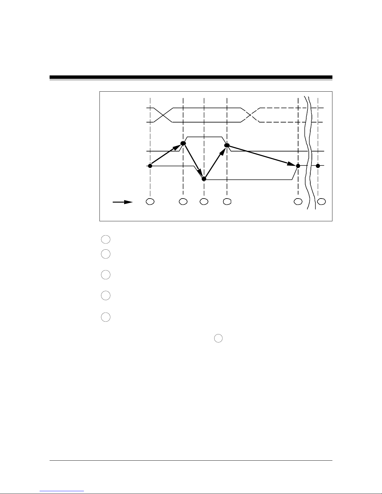
The diagram overleaf illustrates the handshake function.
Driving the Display
Artisan Technology Group - Quality Instrumentation ... Guaranteed | (888) 88-SOURCE | www.artisantg.com
3-2
Driving the Display
PX 30 and PX 120 Operating Manual
Data
Input E22
(PX 30: E14)
HS-Output
...........................................
1 enable
disable
0
1
0
1234 5
1
t
1 HS-output = 1: New data can be supplied.
2 Input E22 (PX 30: E14) may be set from 0 to 1 no earlier than the time at
which the data arrives (enable signal).
3 As a result of the positive-going pulse edge at E22 (PX 30: E14), new data is
read in from the PX-unit and the HS-output is automatically set at 0.
4 Only then is E22 (PX 30: E14) returned to 0. Only at this point can new data
be supplied.
5 As a result of the negative-going pulse edge at E22 (PX 30: E14), the HS-
output automatically returns to 1, but only once the data is processed
by the PX-unit. A Logic 1 signal at the HS-output signals that the unit is
ready to receive new data (see 1 ).
Operating Modes in Display Mode
The following operating modes are supported when the PX is in display mode, with both
parallel and serial drive:
• Text mode
• Variable mode
• Special mode
In text mode, texts are selected and displayed by means of their text number, which can
be either binary or BCD-coded.
Variable mode is used for the selection, evaluation and insertion of variables. Variable
transmission may be binary, BCD or ASCII-coded.
Artisan Technology Group - Quality Instrumentation ... Guaranteed | (888) 88-SOURCE | www.artisantg.com

PX 30 and PX 120 Operating Manual
3-3
For further details of codes and their features, please refer below to the section entitled
"Coding".
In special mode, the following special functions are supported:
• Segment test
• Output of version number
• Automatic display of the text memory contents
• Clear display
• Status display
Parallel Drive through a PLC's I/O-level
Display Mode
Coding
For parallel drive of the PX 30 and PX 120 in display mode, two base settings can be
configured for data coding:
• Binary-coding (default)
• BCD-coding
The required coding method (binary or BCD) is set in the $M-configuration instruction (see
section entitled "Configuration" on page 6-1) and is then used for communicating text
numbers (text selection in text mode).
If no $M-configuration instruction is present, both the PX 30 and PX 120 will operate in
binary code in display mode (default setting).
In variable mode when binary coding has been configured, or the default setting is unchanged, variable values can be transmitted in three ways:
• Binary-coded
• BCD-coded or
• ASCll-coded
If BCD-coding has been configured, variable values can be transmitted in two ways:
• BCD-coded or
• ASCll-coded
The variable code is selected in the 1st cycle of each new variable transmission.
The diagram overleaf shows the function and layout of inputs E0 - E7 in the 1st cycle of
each variable transmission (ID-Byte).
Artisan Technology Group - Quality Instrumentation ... Guaranteed | (888) 88-SOURCE | www.artisantg.com

3-4
Driving the Display
PX 30 and PX 120 Operating Manual
A = 1 Display ASCll-coded variables
A = 0 Display binary or BCD-coded variables
? = 1 "?" flashes alternately with the lowest
value digit of the variable value
? = 0 "?" not inserted
_ = 1 "_" flashes alternately with the lowest
value digit of the variable value
_ = 0 "_" not inserted
N = 1 A negative prefix "-" is placed before
the variable value
N = 0 Display without negative prefix
C = 1 BCD-coding
C = 0 Binary-coding
If E3 = 0, binary coding is selected, if E3 = 1, BCD-coding is selected.
If BCD-coding is selected, the maximum number of BCD-digits per cycle will be transmit-
ted in parallel operation. The maximum number is 4 BCD-digits in 24-input mode and 2
BCD-digits in 16-input mode, provided the $M-configuration instruction has not been used
to reduce the number of digits which can be transmitted in parallel operation in BCDmode (see page 6-1).
Important: Input E3 has no function when BCD-coding is configured.
Please note:
• The configuration for the number of inputs used on the PX 120 (24 or 16-input-mode) is
described in the section entitled "Configuration" from page 6-1 onwards.
• If input E4 is latched, a negative prefix can be placed before a BCD-digit.
Binary mode operates with signed integers.
• The conversion of a positive binary integer into a negative binary integer of the same
value (taking into account the prefix coding in the highest value bit) is carried out as
follows:
7
0
A ?
_
N C
n n n
123456
Input
Variable Number
0 ... 7, binary coded
n n n
Artisan Technology Group - Quality Instrumentation ... Guaranteed | (888) 88-SOURCE | www.artisantg.com
PX 30 and PX 120 Operating Manual
3-5
1. Positive binary integer
2. Complementing (negation) of binary value
3. Add "1"
Example: "-21" as a signed 8-bit binary figure
1. "+21": 00010101
2. 11101010
3. + 00000001
4. 11101011 (on PX-unit): "-21"
Important: You will need to be in variable mode to use input E3 to switch between binary
and BCD-coding. Even in this case, binary coding will need to have been configured, or
the $M-configuration instruction will need to have been omitted!
Text Display with 24 Inputs (PX 120)
Note: The PX 120 can be configured to use just 16 inputs (see page 6-1), making it fully
compatible with the PX 30. The function and layout of inputs in 16-input mode is described from page 3-12 onwards.
Function and Layout of Inputs (general)
E23 = 0 Display Mode
Enable signal (positive-going pulse edge)
B/S Operating Mode/Special Mode: 0/0 = Text Mode; 0/1: Special Mode;
1/0 = Variable Mode; (1/1 = reserved)
e End of data transmission: 1 = last cycle
a Start of data transmission: 1 = first cycle
s Scroll inputs (E17 up; E16 down)
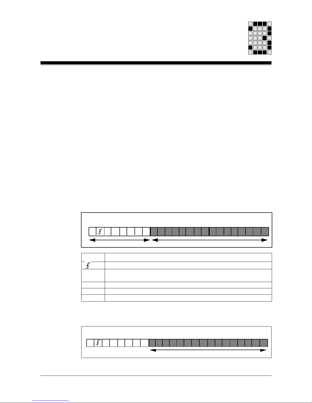
Text Mode
Binary Coding
The text number is interpreted as a signed 16-bit integer. Text numbers from 0 ... 9999
are accepted.
23 22 21 20 19 18 15
00
11
Text Number
w w w w w w w w w w w w w w w w
70
0
7
0
Input
23 22 21 20 19 18 17 16 15
Seass
Control Inputs Data Inputs
B0
23 22 21 20 19 18 15
23 22 21 20 19 18 17 16 15
Artisan Technology Group - Quality Instrumentation ... Guaranteed | (888) 88-SOURCE | www.artisantg.com
 Loading...