

Page 1

18436-3FR-03
PST 4
4
D Betriebsanleitung
4
GB Operating instructions
4
F Manuel d'utilisation
Sicherheitsbestimmungen
• Das Gerät darf nur von Personen
installiert und in Betrieb genommen
werden, die mit dieser Betriebsanleitung
und den geltenden Vorschriften über
Arbeitssicherheit und Unfallverhütung
vertraut sind. Beachten Sie die VDEsowie die örtlichen Vorschriften, insbesondere hinsichtlich Schutzmaßnahmen.
• Beim Transport, der Lagerung und im
Betrieb die Bedingungen nach EN 600682-6 einhalten (s. technische Daten).
• Durch Öffnen des Gehäuses oder
eigenmächtige Umbauten erlischt jegliche
Gewährleistung.
• Montieren Sie das Gerät in einen
Schaltschrank; Staub und Feuchtigkeit
können sonst zu Beeinträchtigungen der
Funktionen führen.
• Sorgen Sie an allen Ausgangskontakten
bei kapazitiven und induktiven Lasten für
eine ausreichende Schutzbeschaltung.
• Hinweis für Überspannungskategorie III:
Wenn am Gerät höhere Spannungen als
Kleinspannung (>50 V AC oder
>120 V DC) anliegen, müssen angeschlossene Bedienelemente und Sensoren eine Bemessungsisolationsspannung
von mind. 250 V aufweisen.
Safety Regulations
• The unit may only be installed and
operated by personnel who are familiar
with both these instructions and the
current regulations for safety at work and
accident prevention. Follow local
regulations especially as regards
preventative measures.
•
Transport, storage and operating
conditions should all conform to
EN 60068-2-6.
• Any guarantee is void following opening of
the housing or unauthorised modifications.
• The unit should be panel mounted,
otherwise dampness or dust could lead to
faults.
• Adequate protection must be provided on
all output contacts with capacitive and
inductive loads.
• Note for overvoltage category III:
If voltages higher than low voltage
(>50 VAC or >120 VDC) are present on
the unit, connected control elements and
sensors must have a rated insulation
voltage of at least 250 V.
Conseils préliminaires
• La mise en oeuvre de l'appareil doit être
effectuée par une personne spécialisée
en installations électriques, en tenant
compte des prescriptions des différentes
normes applicables (NF, EN, VDE..),
notamment au niveau des risques
encourus en cas de défaillance de
l'équipement électrique.
• Respecter les exigences de la norme
EN 60068-2-6 lors du transport, du
stockage et de l'utilisation de l'appareil.
• Toutes interventions sur le boîtier
ouverture du relais, échange ou
modification de composants, soudure
etc..) faites par l'utilisateur annule la
garantie.
• Montez l'appareil dans une armoire
électrique à l'abri de l'humidité et de la
poussière.
• Assurez-vous du pouvoir de coupure des
contacts de sortie en cas de charges
inductives ou capacitives.
• Remarque relative à la catégorie de
surtensions III :
Si l’appareil est alimenté avec des tensions
supérieures à la basse tension (>50 V AC
ou >120 V DC), les éléments de
commande et les capteurs raccordés
doivent supporter une tension d’isolement
assignée d’au moins 250 V.
Bestimmungsgemäße Verwendung
Der Schutztürwächter PST 4 ist für folgende
Einsätze bestimmt:
• Schutztürüberwachungen
• Sicherheitsstromkreisen nach VDE 0113
Teil 1 und EN 60204-1
(z. B. bei beweglichen Verdeckungen)
Gerätebeschreibung
Der Schutztürwächter PST 4 ist in einem
P-93-Gehäuse untergebracht. Es stehen
verschiedene Varianten für den Betrieb mit
Wechselspannung und eine Variante für den
Betrieb mit Gleichspannung zur Verfügung.
Merkmale:
• Relaisausgänge: sechs Sicherheitskontakte (Schließer) und vier Hilfskontakte (Öffner), zwangsgeführt
• Anschlussmöglichkeit für Schutztürgrenztaster und Starttaster
• Statusanzeige für Ein- und Ausgänge
sowie Versorgungsspannung
• Rückführkreis zur Überwachung
externer Schütze
Der Schutztürwächter erfüllt folgende
Sicherheitsanforderungen:
• Schaltung ist redundant mit Selbstüberwachung aufgebaut.
• Sicherheitseinrichtung bleibt auch bei
Ausfall eines Bauteils oder bei Kurzschluss an den Grenztastern wirksam.
• Bei jedem Ein-Aus-Zyklus der Maschine
wird automatisch überprüft, ob die Relais
der Sicherheitseinrichtung richtig öffnen
und schließen.
• PST 4 ist mit einer elektronischen
Sicherung ausgestattet.
Typical Applications
The Safety Gate Monitor PST 4 is for use in:
• Safety Gate Monitoring
• Safety Circuits according to VDE 0113
part 1 and EN 60204-1
(e.g. with movable guards).
Description
The Safety Gate Monitor PST 4 is enclosed
in a P-93 housing. There are different
versions available for AC operation and one
for DC operation.
Features:
• Relay outputs: six safety contacts (N/O)
and four auxiliary contacts (N/C), positive
guided.
• Connections for Safety Gate Limit Switch
and Reset Button.
• Status Indicators for inputs, outputs and
power
• Feedback Control Loop for monitoring of
external contactors/relays.
The relay complies with the following safety
requirements:
• The circuit is redundant with built-in selfmonitoring.
• The safety function remains effective in
the case of a component failure or a
short-circuit in the limit switches.
• The correct opening and closing of the
safety function relays is tested
automatically in each on-off cycle.
• PST 4 is fitted with an electronic fuse.
- 1 -
Domaines d'utilisation
Le relais de surveillance des protecteurs
PST 4 est destiné :
• à la surveillance des protecteurs
• aux circuits de sécurité selon les normes
NF 79-130 et EN 60-204/1 (ex.
protecteurs mobiles).
Description de l'appareil
Inséré dans un boîtier P-93, le relais de
surveillance des protecteurs PST 4 est
disponible en différentes versions pour les
tensions d’alimentation alternatives et une
version en alimentation continue (24 VDC).
Particularités :
• Contacts de sortie : 6 contacts à
fermeture de sécurité + 4 contacts à
ouverture pour information
• Raccordement des fins de course et d'un
poussoir de réarmement
• Leds de visualisation pour les canaux
d'entrée, les contacts de sortie et la
tension d'alimentation
• Boucle de retour pour la surveillance des
contacteurs externes.
Le bloc logique PST 4 présente les
caractéristiques suivantes :
• Conception redondante
• Fonction de sécurité assurée même en
cas de défaillance d'un composant ou de
court-circuit sur les fins de course.
• Test cyclique des relais internes à
chaque mise sous tension de la machine
• Protection par fusible électronique.
Page 2
Funktionsbeschreibung
Der Schutztürwächter PST 4 dient dem
sicherheitsgerichteten Unterbrechen eines
Sicherheitsstromkreises. Nach Anlegen der
Versorgungsspannung (LED „Netz“
leuchtet), Brücken zwischen Y1-Y2 und
S33-S34 sowie geöffneten Eingangskreisen
sind alle Relais abgefallen. Werden die
beiden Eingangskreise innerhalb der Zeit t
(Gleichzeitigkeitsbedingung) geschlossen,
gehen die beiden Ausgangsrelais K1 und K2
in Arbeitsstellung, die Sicherheitskontakte
schließen und die Hilfskontakte öffnen. Sind
die Eingangskreise bereits umgeschaltet,
bevor die Versorgungsspannung angelegt
wird, verhindert das PST 4 die Freigabe der
Anlage, um ein selbsttätiges Anlaufen
gemäß EN 60204 T 7.5 zu vermeiden. Wird
ein Kontakt in den Eingangskreisen betätigt,
fallen beide Relais K1 und K2 ab. Die
zwangsgeführten Sicherheitskontakte
öffnen und die Hilfskontakte schließen.
Bevor das Gerät erneut gestartet werden
kann, muss der Rückführkreis geschlossen
werden.
• Reset
Die Sicherheits- und Hilfskontakte bleiben
in Ruhestellung, wenn die Versorgungsspannung bei geschlossener Schutztür
angelegt wird. Öffnerkontakte in Reihe zu
den Grenztastern S1 und S2 (in Fig. 6
Taster S3) können dann das Öffnen der
Schutztür simulieren.
• Eingangskreis wieder geöffnet:
K1 und K2 fallen in Ruhestellung,
Sicherheitskontakte werden redundant
geöffnet, die Hilfskontakte geschlossen.
Function Description
The relay PST 4 provides a safety-oriented
interruption of a safety circuit. When the
operating voltage is supplied (LED 'power'
illuminates), Y1 - Y2 and S33 - S34 are
bridged and the input circuit is opened, all
relays drop-out. If both input circuits are
closed within the time tg (Simultaneity
requirement), the two output relays K1 and
g
K2 energise, the safety contacts close and
the signal contacts open. If the input circuits
are already closed before the operating
voltage is supplied, the PST 4 prevents
machine operation to avoid an independent
start-up according to EN 60204 Pt. 7.5. If a
contact in the input circuits is activated, both
relays K1 and K2 de-energise. The positiveguided safety contacts open and the signal
contacts close. The unit can only be reset if
the feedback control loop is closed.
• Reset
The safety and signal contacts remain in
the starting position, if the supply voltage is
connected with the safety gate closed. N/
C contacts in series with the limit switches
S1 and S2 (in Fig. 6, switch S3) can
simulate the opening of the safety gate.
• Input circuit re-opened.
K1 and K2 go to the starting position, the
safety contacts are redundantly opened,
the signal contacts closed.
Description du fonctionnement
Le relais de surveillance des protecteurs
PST 4 permet la coupure, de façon sûre,
d'un circuit de sécurité. Après la mise sous
tension (LED „Netz“allumée), si les canaux
d'entrée sont ouverts et les bornesY1-Y2 et
S33-S34 pontées, tous les relais internes
sont en position repos. Si les deux canaux
d'entrée sont fermées pendant le temps t
(synchronisation temporelle), les deux relais
de sortie K1 et K2 passent en position de
travail, les contacts de sécurité se ferment
et les contacts d'information s'ouvrent. Si
les canaux d'entrée sont en position de
travail avant la mise sous tension du boîtier,
le PST 4 reste au repos et empêche ainsi le
redémarrage l'installation, afin d'éviter une
mise en marche automatique selon la norme
EN 60204 T 7.5. Si les canaux d'entrée sont
ouverts, les deux relais K1 et K2 retombent.
Les contacts de sécurité s'ouvrent et les
contacts d'information se ferrment. Avant
que l'appareil ne puisse être réarmé, la
boucle de retour doit être fermée.
• Réarmement
Les contacts de sortie restent en position
repos après la mise sous tension du
boîtier si les canaux d'entrée sont
fermés. Deux contacts à ouverture
placés en série avec les capteurs S1 et
S2 (Fig. 6, poussoir S3) peuvent alors
simuler l'ouverture de la porte.
• Ouverture des canaux d'entrée :
K1 et K2 passent en position repos, les
contacts de sécurité s'ouvrent, les
contacts d'information se ferment.
g
A1
A: Einschaltlogik, zyklischer Test,
(L+)
Steuerlogik/
Starting logic, cycle test,
control logic/
Logique d'entrée, test cyclique,
*
F1
logique de commande
1: Kanal 1/Channel 1/canal1
G1
2: Kanal 1/Channel 2/canal 2
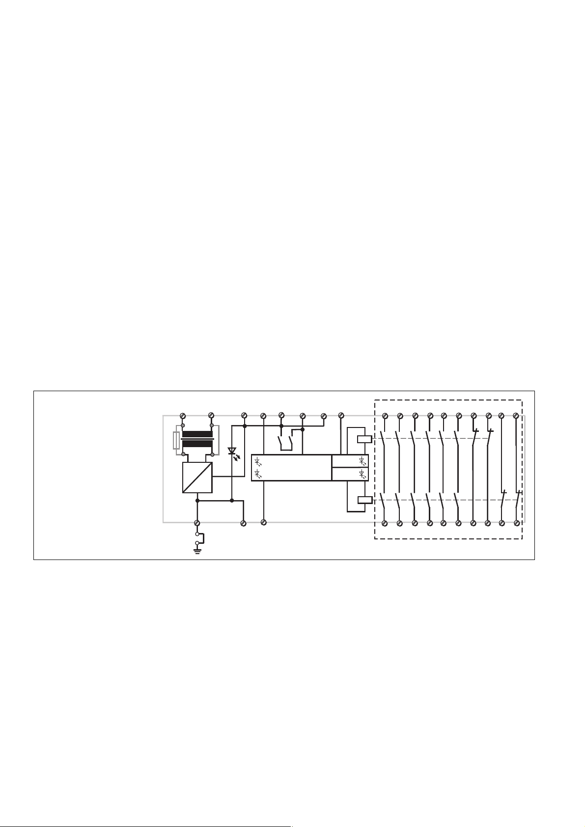
Fig. 1
Schematisches Schaltbild/
Connection Diagram/
Schéma interne
* Isolation zum nicht markierten Bereich und der
Relaiskontakte zueinander: Basisisolierung
(Überspannungskategorie III), sichere
Trennung (Überspannungskategorie II)
Betriebsarten:
• Zweikanaliger Betrieb: Redundanter
Eingangskreis; Erdschlüsse und Querschlüsse im Tasterkreis werden erkannt.
• Automatischer Start: Gerät ist aktiv,
sobald Eingangskreis geschlossen.
• Manueller Start: Gerät ist erst dann aktiv,
wenn ein Starttaster betätigt wird.
• Kontaktvervielfachung und -verstärkung
durch Anschluss von externen Schützen; Funktionsüberwachung der
externen Schütze durch Einschleifen
von Öffnerkontakten der Schütze K3
und K4 in Reihe zu den Klemmen Y1-Y2;
über die Wahl ein- oder zweikanalige
Ansteuerung entscheidet das geforderte
Sicherheitsniveau.
A2
(L-)
~
S11 S12
K1
+
Y1
K2
A
=
S23 S24
* Insulation between the non-marked area
and the relay contacts: Basic insulation
(overvoltage category III), safe separation
(overvoltage category II)
Operating Modes
• Two-channel operation: Redundancy in
the input circuit; earth faults and shorts
across contacts are detected in the
emergency stop circuit.
• Automatic reset: Unit is active, as soon as
the input circuit is closed.
• Manual reset: Unit is only active, when a
start button has been pressed.
• Increase in the number of available
contacts by connection of external
contactors/relays. Functional monitoring of
external contactors/relays by connecting
N/C contacts of relays K3 and K4 into the
existing circuit in series to the terminals Y1
- Y2; The use of 1- or 2-channel drive
depends on the risk level of your machine.
- 2 -
Y2S33 S34
K1
13 23
33 43
53 63
71 81
91 01
*
1
2
K2
14 24
34 44
54 64
* Isolation de la partie non sélectionnée par
rapport aux contacts relais : isolation basique
(catégorie de surtensions III), isolation
galvanique (catégorie de surtensions II)
Modes de fonctionnement :
• Commande en 2 canaux : rédondance
dans les canaux d'entrée : mise à la
terre et court-circuit entre les canaux
d'entrée sont détectés.
• Réarmement automatique :le PST 4 est
actif dès que les canaux d'entrée sont
fermés.
• Réarmement manuel : le PST 4 n'est actif
qu'après une impulsion sur le poussoir de
réarmement.
• Augmentation du nombre des contacts de
sécurité ou de leur pouvoir de coupure à
l'aide de contacteurs externes.
Surveillance des contacteurs externes
par câblage de contacts à ouverture de
K3 et K4 en série entre les bornes Y1-Y2;
le choix de la commande par 1 contact ou
par 2 contacts dépend du niveau de
sécurité de votre installation.
72 82
92 02
Page 3

Montage
Das Sicherheitsschaltgerät muss in einen
Schaltschrank mit einer Schutzart von
mind. IP54 eingebaut werden. Zur Befestigung auf einer Normschiene dient ein
Rastelement auf der Rückseite des Geräts.
Installation
The safety relay must be panel mounted
(min. IP54). There is a notch on the rear of
the unit for DIN-Rail attachment.
Montage
Le relais doit être monté en armoire ayant
un indice de protection mini IP54. Sa face
arrière permet un montage sur rail DIN.
Inbetriebnahme
Beachten Sie bei der Inbetriebnahme:
• Nur die Ausgangskontakte 13-14/23-24/
33-34/43-44/53-54/63-64 sind
Sicherheitskontakte, Ausgangskontakte
71-72/81-82/91-92/01-02 sind Hilfskontakte (z. B. für Anzeige).
• Hilfskontakte 71-72/81-82/91-92/01-02
nicht für Sicherheitsstromkreise
verwenden!
• Schalten Sie vor die Ausgangskontakte eine Sicherung (10 A flink
oder 6 A träge), um das Verschweißen
der Kontakte zu verhindern.
• Eingangskreis:
Max. Leitungslängen: 3,5 km
Voraussetzungen:
Leiterquerschnitt: 2 x 1,5 mm
Kapazität: 150 nF/km
Widerstand: 28 Ohm/km
Temperatur: +25 °C
Leitungswiderstand: 100 Ohm
• Bei 24 V DC-Geräten:
Das Netzteil muss den Vorschriften für
Funktionskleinspannungen mit sicherer
elektrischer Trennung (SELV, PELV)
nach VDE 0100, Teil 410 entsprechen.
• Leitungsmaterial aus Kupferdraht mit
einer Temperaturbeständigkeit von
60/75 °C verwenden.
• Das Anzugsdrehmoment der Schrauben
auf den Anschlussklemmen darf max.
0,6 Nm betragen.
• Angaben im Kapitel „Technische Daten“
unbedingt einhalten.
Ablauf:
• Versorgungsspannung an Klemmen A1
(+) und A2 (–) anlegen.
- DC: Klemme A2 (–) mit geerdeter Seite
der Versorgungsspannung verbinden.
- AC: Betriebserdungsklemme mit
Schutzleitersystem verbinden.
• Rückführkreis schließen
Brücke oder Öffner von externem Schütz an
Y1-Y2 anschließen.
Der Rückführkreis muss mind. 500 ms vor
Betätigen des Grenztasters S1 geschlossen
sein und darf erst nach Betätigen von
Grenztaster S1 geöffnet werden.
• Startkreis schließen
- automatischer Start: S33-S34 brücken
(Fig. 2 und 4).
- manueller Start: Taster an S33-S34
anschließen (Fig. 3 und 5).
• Eingangskreis schließen
Öffnerkontakte von Auslöseelement
(Grenztaster S1 und S2) an S11-S12/
S23-S24 anschließen.
Die Sicherheitskontakte sind aktiviert
(geschlossen) und die Hilfskontakte
geöffnet. Die Statusanzeigen der Ein- und
Ausgänge von Kanal 1 und Kanal 2
leuchten. Das Gerät ist betriebsbereit.
Wird der Eingangskreis wieder geöffnet,
öffnen die Sicherheitskontakte und die
Hilfskontakte schließen. Die Statusanzeige
erlischt.
Wieder aktivieren
• Eingangskreis schließen.
• Bei manuellem Start zusätzlich Taster
zwischen S33 und S34 betätigen.
• Die Statusanzeigen leuchten wieder, die
Sicherheitskontakte sind geschlossen.
Operation
Please note for operation:
• Only the output contacts 13-14/23-24/3334/43-44/53-54/63-64 are safety contacts.
Output contacts 71-72/81-82/91-92/01-02
are auxiliary contacts (e.g. for a display).
• Do not use auxiliary contacts 71-72/
81-82/91-92/01-02 for safety circuits!
• To prevent a welding together of the
contacts, a fuse (10 A quick/6 A slow
acting) must be connected before the
output contacts.
• Input circuit:
Max.cable run: 3.5 km
Cable: 2 x 1.5 mm
Capacitance: 150 nF/km
Resistance: 28 Ohm/km
2
Temperature: + 25 °C
Cable resistance: 100 Ohm
• For 24 V DC units:
The power supply must comply with the
regulations for extra low voltages with
safe electrical separation (SELV, PELV) in
accordance with VDE 0100, Part 410.
• Use copper wiring that will withstand
60/75 °C
• Tighten terminals to 0.6 Nm.
• Important details in the section "Technical
Data" should be noted and adhered to.
To operate:
• Supply operating voltage to terminals A1
(+) and A2 (-).
- DC: Connect terminal A2 (-) with the
earthed side of the operating voltage.
- AC: Connect the operating earth
terminal with the ground earth.
• Close the feedback control loop.
Bridge Y1 - Y2 or connect external
contactors/relays.
The feedback control loop must be closed
at least 500 ms before the limit switch S1
is activated, and may only be opened after
the limit switch S1 is activated.
• Close the activation circuit
- Automatic reset: Bridge S33 - S34
(Diag. 2 and 4).
- Manual reset: Connect button on S33 -
S34 (Diag. 3 and 5).
• Close the input circuit.
Connect N/C contact from trigger element
(Limit switch S1 and S2) to S11-S12/S23S24.
The safety contacts are activated (closed)
and the auxiliary contacts open. The status
indicators from channel 1 and channel 2 are
illuminated. The unit is ready for operation.
If the input circuit is re-opened, the safety
contacts open and the auxiliary contacts
close. The status indicator goes out.
Reactivation
• Close the input circuit.
• With manual reset, the button between
S33-S34 must also be pressed.
• The status indicators light up again, the
safety contacts are closed.
- 3 -
Mise en oeuvre
Tenez compte des points suivants :
• seuls les contacts 13-14/23-24/33-34/4344/53-54/63-64 ssont des contacts de
sécurité, les contacts 71-72/81-82/9192/01-02 sont des contacts d'information.
• Ne pas utiliser le contacts
d’information 71-72/81-82/91-92/01-02
pour les circuits de commande de
sécurité !
• Protégez les contacts de sortie par
des fusibles (10 A rapides ou 6 A
normaux) pour éviter leur soudage.
• Circuits d'entrée :
2
longueur max. du câblge : 3,5 km
Préalables :
Câble : 2 x 1,5 mm
Capacité : 150 nF/km
Résistivité : 28 Ohm/km
Température : +25 °C
Résistivité max. du câblage :100 Ohm
• Pour 24 V appareils DC:
L'alimentation doit satisfaire aux
prescriptions relatives aux tensions
extra basses avec une isolation
électrique de sécurité (SELV, PELV)
selon VDE 0100, partie 410.
• Utiliser uniquement des fils de cablâge en
cuivre 60/75 °C.
• Le couple de serrage sur les bornes de
racordement ne doît pas dépasser
0,6 Nm.
• Respectez les données indiquées dans
les caractéristiques techniques
Mise en oeuvre :
• Amenez la tension d'alimentation sur les
bornes A1 (+) et A2 (–).
- DC : bornes A2 (–) à relier au potentiel
mis à la terre
- AC : relier la borne de terre de l'appareil
• Fermeture de la boucle de retour
Pont ou contacts à ouverture des
contacteurs externes à câbler sur Y1-Y2.
La boucle de retour doit être fermée au
minimum 500 ms avant que le capteur S1
ne soit actionné et ne peut être ouverte
qu'après l'action sur S1.
• Cicuit de réarmement
- réarmement automatique : bornes
S33-S34 pontées (Fig. 2 et 4).
- réarmement manuel : câblage d'un
poussoir sur les bornes S33-S34 (Fig.
3 et 5).
• Fermeture des canaux d'entrée
Câblage des contacts des capteurs sur
les bornes S11-S12/S23-S24.
Les contacts de sécurité se ferment et les
contacts d'information s'ouvrent. Les Leds
des canaux d'entrée et de sortie sont
allumées.
Si les canaux d'entrée sont ouverts, les
contacts de sécurité retombent et les
contacts d'information se ferment. Les Leds
de visualisation sont éteintes.
Nouvelle fermeture du protecteur
• Fermeture des canaux d'entrée.
• En cas de réarmement manuel, action
sur le poussoir de réarmement
• Les affichages d'état s'allument à
nouveau. Les contacts de sécurité sont
fermées.
2
Page 4

S34
Y2
Y1
S33
S11
S24
S12
S1
S2
S23
S11
Y1
S33
S11
Y1
S33
S1
S12
S23
S2
Y2
S34
S24
Fig. 2: zweikanalige Schutztürsteuerung,
automatischer Start/Two-channel safety
gate control, automatic reset/commande
par 2 canaux avec validation automatique
Y1
S11
S12
S23
S33
S1
S3
S2
S1
S12
S23
S2
S24
Y2
S3
S34
Fig. 3: zweikanalige Schutztürsteuerung,
manueller Start/
Two-channel safety gate control, manual
reset/commande par 2 canaux avec
validation manuelle
S11
S1
S2
S3
S12
Y1
Fig. 4: zweikanalige Schutztürsteuerung,
automatischer Start und Anlauftestung/Twochannel safety gate control, automatic reset
with start-up testing/commande par 2
canaux et test des conditions initiales
L1
K3 K4
Y1
Y2
13
14
S24
Y2
S34
Fig. 5: zweikanalige Schutztürsteuerung, manueller Start und Anlauftestung/Two-channel safety gate
control, manual reset with start-up
testing/commande par 2 canaux avec
test des conditions initiales et validation
S24
Fig. 6: Resetbeschaltung, erst durch Betätigen von S3 wird PST 4 aktiviert/
reset wiring, PST 4 is only energised when
S3 is activated/réarmement par poussoir
S3
S23
Y2
N
Fig 7: Kontaktvervielfältigung bzw. -verstärkung durch einkanalige Ansteuerung/
Increase in the number of available
contacts, single-channel drive/
augmentation du nombre des contacts,
commande par 1 canal
manuelle
S1/S2: Not-Halt-bzw.Schutztürschalter/Emergency Stop Button, Safety Gate Limit Switch/Poussoir AU, détecteurs de position
S3: Starttaster/Reset button/Poussoir de réarmement
betätigtes Element/Switch
activated/élément actionné
Fehler - Störungen
• Erdschluss: Eine elektronische Sicherung
bewirkt das Öffnen der Ausgangskontakte.
Nach Wegfall der Störungsursache und
bei vorhandener Versorgungsspannung
ist das Gerät nach ca. 1 s wieder
betriebsbereit.
AC: Gerät aus- und einschalten, wenn es
trotz Störungswegfall nicht betriebsbereit
ist.
• Fehlfunktionen der Kontakte: Bei ver-
• LED "Kan. 1 Ausg." und "Kan. 2 Ausg."
schweißten Kontakten ist nach Öffnen
des Eingangskreises keine neue
Aktivierung möglich.
leuchten nicht: Es ist nur ein Grenztaster
geschlossen; Gleichzeitigkeit wurde nicht
eingehalten.
Tür nicht geschlossen/Gate
open/porte ouverte
Faults
• Earth fault: An electronic fuse causes the
output contacts to open.
Once the short circuit is removed, the unit
is ready for reset after 1 s.
AC: Switch unit off and on again if the unit
is not ready for operation despite removal
of the disturbance.
• Faulty contact functions: In the case of
welded contacts, no further activation is
possible following an opening of the input
circuit.
• LED's 'channel 1 output' and 'channel 2
output' do not illuminate: Only one limit
switch is closed; Simultaneity has not
been maintained.
Tür geschlossen/Gate
closed/porte fermée
Défauts
• Mise à la terre : un fusible électronique
protège l'appareil et ouvre les contacts de
sortie.
L'appareil est à nouveau prêt à
fonctionner env. 1 sec. après la
disparition du défaut.
AC : une coupure de l'alimentation du
boîtier peut être nécessaire après la
disparition du défaut.
• Défaillance d'un contact : en cas de
soudure d'un contact interne, une
nouvelle commande du relais est
impossible.
• Leds "Kan. 1 Ausg." et "Kan. 2 Ausg."
éteintes : un seul capteur est actionné ou
le temps de désynchronisme est
dépassé.
K3
K4
- 4 -
Page 5

Technische Daten
Technical details
Caractéristiques techniques
Elektrische Daten
Versorgungsspannung U
Spannungstoleranz U
Leistungsaufnahme bei U
B
B
B
Frequenzbereich
Restwelligkeit
Spannung und Strom an
S11/S12, S23/S24
Anzahl der Ausgangskontakte
Sicherheitskontakte (S)
Hilfskontakte (Ö)
Gebrauchskategorie nach
EN 60947-4-1
EN 60947-5-1
(DC13: 6 Schaltspiele/Min.)
Kontaktmaterial
Kontaktabsicherung extern
EN 60947-5-1 (IK = 1 kA)
Schmelzsicherung
Sicherungsautomat,
Charakteristik B/C
Sicherheitstechnische
Kenndaten
PL nach EN ISO 13849-1: 2006
Kategorie nach EN 954-1
SIL CL nach EN IEC 62061
PFH nach EN IEC 62061
SIL nach IEC 61511
PFD nach IEC 61511
TM [Jahr] nach EN ISO 13849-1:
2006
Zeiten
Anzugsverzögerung
Rückfallverzögerung
Einschaltdauer
Gleichzeitigkeitsbedingung (max.
Zeitdifferenz tg zwischen Kanal 1
und Kanal 2)
Umweltdaten
EMV
Schwingungen nach EN 60068-2-6
Frequenz
Amplitude
Klimabeanspruchung
Luft- und Kriechstrecken nach
EN 60947-1
Verschmutzungsgrad
Überspannungskategorie
Bemessungsisolationsspannung
Bemessungsstoßspannungs-
festigkeit
Umgebungstemperatur
Lagertemperatur
Schutzart
Einbauraum (z. B. Schaltschrank)
Gehäuse
Klemmenbereich
Electrical data
Supply voltage U
Voltage tolerance U
Power consumption at U
B
B
B
Frequency Range
Residual ripple
Voltage and current at
S11/S12, S23/S24
Number of output contacts
Safety contacts N/O
Auxiliary contacts N/C
Utilization category in accordance with
EN 60947-4-1
EN 60947-5-1
(DC13: 6 cycles/min)
Contact material
External contact fuse protection
EN 60947-5-1 (IK = 1 kA)
blow-out fuse
Circuit breaker,
characteristic B/C
Safety-related characteristic
data
PL in accordance with
EN ISO 13849-1: 2006
Category in accordance with
EN 954-1
SIL CL in accordance with
EN IEC 62061
PFH in accordance with
EN IEC 62061
SIL in accordance with IEC 61511
PFD in accordance with IEC 61511
TM [year] in accordance with
EN ISO 13849-1: 2006
Times
Delay-on Energisation
Delay-on de-energisation
Duty Cycle
Simultaneity Requirements (max.
Time delay tg between channel 1 and
channel 2)
Environmental data
EMC
Vibration to EN 60068-2-6
Frequency
Amplitude
Climate Suitability
Airgap Creepage in accordance
with EN 60947-1
Pollution degree
Overvoltage category
Rated insulation voltage
Rated impulse withstand voltage
Ambient temperature
Storage temperature
Protection type
Mounting (eg. cabinet)
Housing
Terminals
Données électriques
Tension d’alimentation U
B
Plage de la tension d'alimentation U
Consommation pour U
B
Fréquence
Ondulation résiduelle
Tension et courant sur
S11/S12, S23/S24
Nombre de contacts de sortie
Contacts de sécurité (F)
Contacts d'info (O)
Catégorie d’utilisation selon
EN 60947-4-1
EN 60947-5-1
(DC13: 6 manoeuvres/min)
Matériau contact
Protection des contacts externe
EN 60947-5-1 (IK = 1 kA)
fusible
Disjoncteur,
caractéristique B/C
Caractéristiques techniques de
sécurité
PL selon EN ISO 13849-1: 2006
Catégorie selon EN 954-1
SIL CL selon EN IEC 62061
PFH selon EN IEC 62061
SIL selon IEC 61511
PFD selon IEC 61511
TM [année] selon EN ISO 13849-1:
2006
Temporisations
Temps d'appel
Temps de retombée
Durée de fonctionnement
Synchronisation temporelle
(différence de temps tg max. entre
les canaux 1 et 2)
Données sur l'environnement
CEM
Vibrations selon EN 60068-2-6
Fréquences
Amplitude
Conditions climatiques
Cheminement et claquage selon
EN 60947-1
Niveau d'encrassement
Catégorie de surtensions
Tension assignée d'isolement
Tension assignée de tenue aux
chocs
Température d’utilisation
Température de stockage
Indice de protection
Lieu d'implantation (ex. armoire)
Boîtier
Bornes
AC: 24, 42, 110, 230, 240 V
DC: 24 V
-15 % ... +10 %
B
5,5 W; 12 VA
AC: 50 ... 60 Hz
DC: max. 20%
24 V DC, 30 mA
6
4
AC1: 240 V/0,01... 8 A/
2000 VA
400 V/0,01...5A/2000 VA
DC1: 24 V/0,01...8 A/200 W
AC15: 230 V/5 A;
DC13: 24 V/7 A
AgSnO2+ Au
10 A flink/quick acting/rapide
6 A träge/slow acting/
normal
24 V AC/DC: 10 A,
230 V AC: 2A
PL e (Cat. 4)
Cat. 4
SIL CL 3
5,14E-09
SIL 3
4,98E-06
20
ca./appx./env. 100 ms
ca./appx./env. 50 ms
100 %
ca./appx./env. 4 s
EN 60947-5-1, EN 61000-6-2
10-55 Hz
0,35 mm
EN 60068-2-30
2
III / II
400 V
4 kV
-10 ... + 55 °C
-40 ... +85 °C
IP54
IP40
IP20
- 5 -
Page 6

Mechanische Daten
Gehäusematerial
Gehäuse
Querschnitt des Außenleiters
(Schraubklemmen)
1 Leiter, flexibel
2 Leiter gleichen Querschnitts,
flexibel mit Aderendhülse, ohne
Kunststoffhülse
ohne Aderendhülse oder mit
TWIN-Aderendhülse
Anzugsdrehmoment für
Anschlussklemmen (Schrauben)
Abmessungen H x B x T
Gewicht
Mechanical data
Housing material
Housing
Cable cross section (screw
terminals)
1 core, flexible
2 core, same cross section flexible
with crimp connectors, without
insulating sleeve
without crimp connectors or with
TWIN crimp connectors
Torque setting for connection
terminal screw
Dimensions H x W x D
Weight
Données mécaniques
Matériau du boîtier
Boîtier
Capacité de raccordement (borniers
à vis)
1 conducteur souple
2 conducteurs de même diamètre
souple avec embout, sans
chapeau plastique
souple sans embout ou avec
embout TWIN
Couple de serrage (bornier)
Dimensions H x P x L
Poids
PPO UL 94 V0
0,20 ... 4,00 mm2,
24 - 10 AWG
0,20 ... 2,50 mm2,
24 - 14 AWG
0,20 ... 2,50 mm2,
24 - 14 AWG
0,6 Nm
87 x 90 x 121 mm
AC: 700 g
DC: 530 g
ACHTUNG!
Beachten Sie unbedingt die
Lebensdauerkurve der Relais. Die
sicherheitstechnischen Kennzahlen
der Relaisausgänge gelten nur,
solange die Werte der Lebensdauerkurven eingehalten werden.
Der PFH-Wert ist abhängig von der
Schaltfrequenz und der Belastung des
Relaisausganges. Solange die
Lebensdauerkurven nicht erreicht werden,
kann der angegebene PFH-Wert unabhängig von der Schaltfrequenz und der
Belastung verwendet werden, da der PFHWert den B10d-Wert der Relais sowie die
Ausfallraten der anderen Bauteile bereits
berücksichtigt.
Alle in einer Sicherheitsfunktion verwendeten Einheiten müssen bei der Berechnung
der Sicherheitskennwerte berücksichtigt
werden.
INFO
Die SIL-/PL-Werte einer Sicherheits-
funktion sind nicht identisch mit den
SIL-/PL-Werten der verwendeten
Geräte und können von diesen
abweichen. Wir empfehlen zur
Berechnung der
SIL-/PL-Werte der Sicherheitsfunktion das Software-Tool PAScal.
CAUTION!
It is essential to consider the relay’s
service life graphs. The relay outputs’
safety-related characteristic data is
only valid if the values in the service
life graphs are met.
The PFH value depends on the switching
frequency and the load on the relay output.
If the service life graphs are not accessible,
the stated PFH value can be used
irrespective of the switching frequency and
the load, as the PFH value already
considers the relay’s B10d value as well as
the failure rates of the other components.
All the units used within a safety function
must be considered when calculating the
safety characteristic data.
INFORMATION
A safety function’s SIL/PL values are
not identical to the SIL/PL values of
the units that are used and may be
different. We recommend that you
use the PAScal software tool to
calculate the safety function’s SIL/PL
values.
ATTENTION!
Veuillez absolument tenir compte des
courbes de durée de vie des relais. Les
caractéristiques de sécurité des sorties
relais sont uniquement valables tant que
les valeurs des courbes de durée de
vie sont respectées.
La valeur PFH dépend de la fréquence de
commutation et de la charge de la sortie
relais.
Tant que les courbes de durée de vie ne
sont pas atteintes, la valeur PFH indiquée
peut être utilisée indépendamment de la
fréquence de commutation et de la charge
car la valeur PFH prend déjà en compte la
valeur B10d des relais ainsi que les taux de
défaillance des autres composants.
Toutes les unités utilisées dans une fonction
de sécurité doivent être prises en compte
dans le calcul des caractéristiques de
sécurité.
INFORMATION
Les valeurs SIL / PL d’une fonction
de sécurité ne sont identiques aux
valeurs SIL / PL des appareils
utilisés et peuvent varier par rapport
à celles-ci. Pour le calcul des
valeurs SIL / PL de la fonction de
sécurité, nous recommandons l’outil
logiciel PAScal.
Es gelten die 2009-05 aktuellen Ausgaben
der Normen.
Kontaktbelastung
Nennbetriebsspannung 24 V
Zeitkonstante 100 ms
Schalthäufigkeit 500/h
The version of the standards current at
2009-05 shall apply.
Contact Load
Nominal Operating Voltage 24 V
Time Constant 100 ms
Number of Switching Actuations 500/h
Se référer à la version des normes en
vigeur au 2009-05.
Charge des contacts de sortie
Tension nominale 24 V
Constante de temps 100 ms
Fréquence 500/h
Konventioneller thermischer Strom bei gleichzeitiger Belastung mehrerer Kontakte/Conventional thermal
current while loading several contacts/Courant thermique conventionnel en cas de charge sur plusieurs
contacts
Anzahl der Kontakte/number of contacts/nombre des contacts 6 5 4 3 2 1
Ith 4 4,4 5 5,7 7 8
- 6 -
Page 7

Bestelldaten/Order reference/Caractéristiques
Typ/
Type/
Type
PST 4
PST 4
PST 4
PST 4
PST 4
PST 4
Merkmale/
Features/
Caractéristiques
24 V DC
24 V AC
42 V AC
110 V AC
230 V AC
240 V AC
Lebensdauerkurve
Die Lebensdauerkurven geben an, ab
welcher Schaltspielzahl mit verschleißbedingten Ausfällen gerechnet werden
muss. Der Verschleiß wird vor allem durch
die elektrische Belastung verursacht, der
mechanische Verschleiß ist
vernachlässigbar.
Klemmen/
Terminals/
Borniers
Schraubklemmen/screw terminals/borniers à vis
Schraubklemmen/screw terminals/borniers à vis
Schraubklemmen/screw terminals/borniers à vis
Schraubklemmen/screw terminals/borniers à vis
Schraubklemmen/screw terminals/borniers à vis
Schraubklemmen/screw terminals/borniers à vis
Service life graph
The service life graphs indicate the number
of cycles from which failures due to wear
must be expected. The wear is mainly
caused by the electrical load; the
mechanical load is negligible.
Bestell-Nr./
Order no./
Référence
720 300
720 301
720 303
720 308
720 309
720 310
Courbe de durée de vie
Les courbes de durée de vie indiquent à
partir de quel nombre de manoeuvres il faut
s’attendre à des défaillances liées à l’usure.
La charge électrique est la cause principale
de l’usure, l’usure mécanique étant
négligeable.
Beispiel:
Induktive Last: 0,2 A
Gebrauchskategorie: AC15
Lebensdauer der Kontakte: 4 000 000
Schaltspiele
Solange die zu realisierende Applikation nur
eine Schaltspielzahl von weniger als
4 000 000 Schaltspielen erfordert, kann mit
dem PFH-Wert (s. technische Daten)
gerechnet werden.
Um die Lebensdauer zu erhöhen, an allen
Ausgangskontakten für eine ausreichende
Funkenlöschung sorgen. Bei kapazitiven
Lasten sind eventuell auftretende Stromspitzen zu beachten. Bei DC-Schützen
Freilaufdioden zur Funkenlöschung
einsetzen.
Example:
Inductive load: 0,2 A
Utilisation category: AC15
Contact service life: 4 000 000 cycles
Provided the application requires fewer than
4 000 000 cycles, the PFH value (see
technical details) can be used in the
calculation.
To increase the service life, sufficient spark
suppression must be provided on all output
contacts. With capacitive loads, any power
surges that occur must be noted. With
contactors, use freewheel diodes for spark
suppression.
- 7 -
Exemple:
Charge inductive : 0,2 A
Catégorie d’utilisation : AC15
Durée de vie des contacts : 4 000 000
manoeuvres
Tant que l’application à réaliser requière un
nombre de manoeuvres inférieur à
4 000 000, on peut se fier à la valeur PFH
(voir les caractéristiques techniques).
Assurez-vous qu’il y ait une extinction d’arc
suffisante sur tous les contacts de sortie
afin d’augmenter la durée de vie. Faites
attention à l’apparition de pointes de courant
en cas de charges capacitatives. En cas de
contacteurs DC, utilisez des diodes de roue
libre pour l’extinction des étincelles.
Page 8

Abmessungen in mm (")/Dimensions in mm (")/Dimensions en mm (")
121 (4.76")
75 (2.95")
87 (3.42")
EG-Konformitätserklärung:
Diese(s) Produkt(e) erfüllen die Anforderungen der Richtlinie 2006/42/EG über
Maschinen des europäischen Parlaments
und des Rates.
Die vollständige EG-Konformitätserklärung
finden Sie im Internet unter www.pilz.com
Bevollmächtigter: Norbert Fröhlich,
Pilz GmbH & Co. KG, Felix-Wankel-Str. 2,
73760 Ostfildern, Deutschland
90 (3.54")
EC Declaration of Conformity:
This (these) product(s) comply with the
requirements of Directive 2006/42/EC of the
European Parliament and of the Council on
machinery.
The complete EC Declaration of Conformity
is available on the Internet at www.pilz.com
Authorised representative: Norbert Fröhlich,
Pilz GmbH & Co. KG, Felix-Wankel-Str. 2,
73760 Ostfildern, Germany
Déclaration de conformité CE :
Ce(s) produit(s) satisfait (satisfont) aux
exigences de la directive 2006/42/CE
relative aux machines du Parlement
Européen et du Conseil.
Vous trouverez la déclaration de conformité
CE complète sur notre site internet
www.pilz.com
Représentant : Norbert Fröhlich,
Pilz GmbH & Co. KG, Felix-Wankel-Str. 2,
73760 Ostfildern, Allemagne
Technischer Support
+49 711 3409-444 +49 711 3409-444
...
In vielen Ländern sind wir durch
unsere Tochtergesellschaften und
Handelspartner vertreten.
Nähere Informationen entnehmen
Sie bitte unserer Homepage oder
nehmen Sie Kontakt mit unserem
Stammhaus auf.
Technical support
... ...
In many countries we are
represented by our subsidiaries
and sales partners.
Please refer to our Homepage
for further details or contact our
headquarters.
Assistance technique
+49 711 3409-444
Nos filiales et partenaires
commerciaux nous représentent
dans plusieurs pays.
Pour plus de renseignements,
consultez notre site internet ou
contactez notre maison mère.
- 8 -
www
www.pilz.com
Pilz GmbH & Co. KG
Felix-Wankel-Straße 2
73760 Ostfildern, Germany
Telephone: +49 711 3409-0
Telefax: +49 711 3409-133
E-Mail: pilz.gmbh@pilz.de
Originalbetriebsanleitung/Original instructions/Notice originale
18436-3FR-03, 2012-08 Printed in Germany
 Loading...