

Page 1

Operating Manual PSSu E S INC(-T )
Operating Manual PSSu E S INC(-T)
PSSu E S INC(-T)
Decentralised system PSSuniversal I/O
Operating Manual — No. 21447-EN-03
Page 2

This document is a translation of the original document.
All rights to this documentation are reserved by Pilz GmbH & Co. KG. Copies may be made
for internal purposes.
Suggestions and comments for improving this documentation will be gratefully received.
Pilz®, PIT®, PMI®, PNOZ®, Primo®, PSEN®, PSS®, PVIS®, SafetyBUS p®, SafetyEYE®,
SafetyNET p®, the spirit of safety® are registered and protected trademarks of
Pilz GmbH & Co. KG in some countries.
SD means Secure Digital.
Preface
Page 3

Contents
Contents
Contents Page
Chapter 1 Introduction
1.1 Validity of documentation 1-1
1.1.1 Retaining the documentation 1-1
1.1.2 Terminology: System environment A and B 1-1
1.2 Overview of documentation 1-2
1.3 Definition of symbols 1-3
Chapter 2 Overview
2.1 Module structure 2-1
2.1.1 Module features 2-1
2.2 Front view 2-2
Chapter 3 Safety
3.1 Intended use 3-1
3.2 Safety regulations 3-3
3.2.1 Use of qualified personnel 3-3
3.2.2 Warranty and liability 3-3
3.2.3 Disposal 3-3
Chapter 4 Function description
4.1 Module features 4-1
4.1.1 Function description 4-1
4.1.1.1 Functional inputs (G, L, S) 4-1
4.1.1.2 Overflow 4-2
4.1.2 Integrated protection mechanisms 4-2
4.1.3 Incremental encoder operating mode 4-3
4.1.4 Counter operating mode 4-4
4.1.5 Functions 4-5
4.1.5.1 Measure period length 4-5
4.1.5.2 Transfer counter status via latch pulse 4-7
4.1.5.3 Transfer counter status via zero pulse 4-8
4.1.5.4 Set counter status 4-10
4.2 Configuration 4-11
4.2.1 Operating modes and parameters 4-11
4.2.2 Input/output data 4-11
4.2.2.1 PSSu assignment in system environment A 4-11
4.2.2.2 PSSu assignment in system environment B4-14
Pilz GmbH & Co. KG, Felix-Wankel-Straße 2, 73760 Ostfildern, Germany
Telephone: +49 711 3409-0, Telefax: +49 711 3409-133, E-Mail: pilz.gmbh@pilz.de
1
Page 4

Contents
Chapter 5 Installation
5.1 General installation guidelines 5-1
5.1.1 Dimensions 5-1
5.2 Installing the base module 5-2
5.3 Inserting and removing an electronic
module
5.3.1 Inserting an electronic module 5-3
5.3.2 Removing an electronic module 5-4
5.3.3 Changing an electronic module during
operation
Chapter 6 Wiring
6.1 General wiring guidelines 6-1
6.1.1 Mechanical connection of the base
modules
6.2 Terminal configuration 6-4
6.3 Connecting the module 6-5
5-3
5-4
6-2
Chapter 7 Operation
7.1 Messages 7-1
7.2 Display elements 7-2
7.2.1 Display elements for module diagnostics 7-2
7.2.2 Display elements for counter status 7-3
7.2.3 Display elements for status of the
functional inputs
7.3 Status information 7-4
Chapter 8 Technical details
8.1 Technical details 8-1
8.2 Order reference 8-3
7-3
Pilz GmbH & Co. KG, Felix-Wankel-Straße 2, 73760 Ostfildern, Germany
2
Telephone: +49 711 3409-0, Telefax: +49 711 3409-133, E-Mail: pilz.gmbh@pilz.de
Page 5

1 Introduction
1.1 Validity of documentation
11000IntroductionIntroduction1-1.1Validity of docume ntation1100Validity of documenta tion1-][BA Einf Gültigkeit_(T)
This documentation is valid for the products PSSu E S INC and
Einf Einleitung
Bestimm_Verwend_ Zusatz-(T)
1.1.1 Retaining the documentation
Retaining the documentation1-Einf Aufbewahren
PSSu E S INC-T. It is valid until new documentation is published.
This operating manual explains the function and operation, describes
the installation and provides guidelines on how to connect the product .
The module PSSu E S INC-T is suitable for use where there are increased environmental requirements (see Technical Details).
This documentation is intended for instruction and should be retained
for future reference.
1.1.2 Terminology: System environment A and B
Terminology: System environment A and B1-][BA Einf Begriffsdefinition Sys A + B
The PSSu system can be used in two different system environments.
The module's application area is described in the chapter "Intended
Use" of the manual.
The distinction is made between
PSSu in system environment A
PSSu in system environment B
The distinction is based on the application area of the PSSu system.
PSSu in system environment A may be used in the
Decentralised system PSSu I/O with SafetyBUS p
Decentralised system PSSu I/O with ST fieldbuses such as CANopen,
DeviceNet
Not in the automation system PSS 4000
PSSu in system environment B may be used in the
Automation system PSS 4000, e.g. with the
– Decentralised system PSSu I/O with SafetyNET p
– Control system PSSu PLC
– Control system PSSu multi
Pilz GmbH & Co. KG, Felix-Wankel-Straße 2, 73760 Ostfildern, Germany
Telephone: +49 711 3409-0, Telefax: +49 711 3409-133, E-Mail: pilz.gmbh@pilz.de
1-1
Page 6

1 Introduction
1.2 Overview of documentation
1.2Overview of documentation1200Overview of documentation1-][BA Einf Übersicht E-Modul
1 Introduction
The introduction is designed to familiarise you with the contents, structure and specific order of this manual.
2 Overview
This chapter provides information on the product's most important features.
3 Safety
This chapter must be read as it contains important information on safety
and intended use.
4 Function Description
This chapter describes the product's individual components.
5 Installation
This chapter explains how to install the product.
6 Wiring
This chapter describes the product's wiring.
7 Operation
This chapter explains the display elements and advises on what to do if
a fault occurs.
8 Technical Details
This chapter contains the product's technical details and order reference.
1-2
Pilz GmbH & Co. KG, Felix-Wankel-Straße 2, 73760 Ostfildern, Germany
Telephone: +49 711 3409-0, Telefax: +49 711 3409-133, E-Mail: pilz.gmbh@pilz.de
Page 7
1 Introduction
1.3 Definition of symbols
1.3Definition of symbols1300Definition of symbols1-Einfhrung Zeichen
Information that is particularly important is identified as follows:
DANGER!
This warning must be heeded! It warns of a hazardous situation
that poses an immediate threat of serious injury and death and
indicates preventive measures that can be taken.
WARNING!
This warning must be heeded! It warns of a hazardous situation
that could lead to serious injury and death and indicates preventive measures that can be taken.
CAUTION!
This refers to a hazard that can lead to a less serious or minor
injury plus material damage, and also provides information on
preventive measures that can be taken.
NOTICE
This describes a situation in which the unit(s) could be damaged
and also provides information on preventive measures that can
be taken. It also highlights areas within the text that are of particular importance.
INFORMATION
This gives advice on applications and provides information on
special features.
Pilz GmbH & Co. KG, Felix-Wankel-Straße 2, 73760 Ostfildern, Germany
Telephone: +49 711 3409-0, Telefax: +49 711 3409-133, E-Mail: pilz.gmbh@pilz.de
1-3
Page 8

1 Introduction
1-4
Pilz GmbH & Co. KG, Felix-Wankel-Straße 2, 73760 Ostfildern, Germany
Telephone: +49 711 3409-0, Telefax: +49 711 3409-133, E-Mail: pilz.gmbh@pilz.de
Page 9

2 Overview
2.1 Module structure
22000OverviewOverview2-2.1Module structure2100Module structure2-][BA Übersicht Aufbau
A module consists of
Electronic module and
Base module with
The base modules are the carrier units for the electronic modules and
are used to connect the field wiring. The electronic modules are inserted
on to the base modules and determine the module's function.
Details of the base modules that can be used are available in the chapter
entitled “Intended Use”.
– Screw terminals or
– Cage clamp terminals
2.1.1 Module features
Module features2-Geraetemerkmale_Zusatz BA Einleitung
][Merkmale_Ein_Aus INC
][Merkmale_LED IN C
][Merkmale_Zusatz ST-Module Sys A + B
][Geraetemerkmal_T
The product has the following features:
Inputs for
– Counter pulses (inputs A, B)
– Zero pulse (Input C)
– Stopping the counter (Input G, Gate)
– Memory function (Input L, Latch)
– Rotary encoder status (Input S, Status)
Resolution of the counter and latch memory: 32 Bit
Operating modes:
– Incremental encoders
–Counters
Inputs A, B, C are operated as differential inputs with inverted signals
(A-, B-, C-).
Pulse multiplication (up to four times)
LEDs for:
– Data transfer per input A, B, C
– Status per functional input (Gate, Latch, Status)
– Module error
For standard applications in system environment A and B
Coated version of the module:
PSSu E S INC-T: for increased environmental requirements
Pilz GmbH & Co. KG, Felix-Wankel-Straße 2, 73760 Ostfildern, Germany
Telephone: +49 711 3409-0, Telefax: +49 711 3409-133, E-Mail: pilz.gmbh@pilz.de
2-1
Page 10
2 Overview
2111
2212
2414
4131
4232
4434
2313 4333
Err
11
A+
120V22
0V
13
(C)23(C)
PSSu E S
INC
32S42
S
33
(C)43(C)
G
S
A
B
C
L
21
B+
14A-24
B-
41C+41
G
34C-44
L
PSSu E S
INC
312485
000000
001
10
1
3
4
9
8
5
6
7
11
2
12
A
B
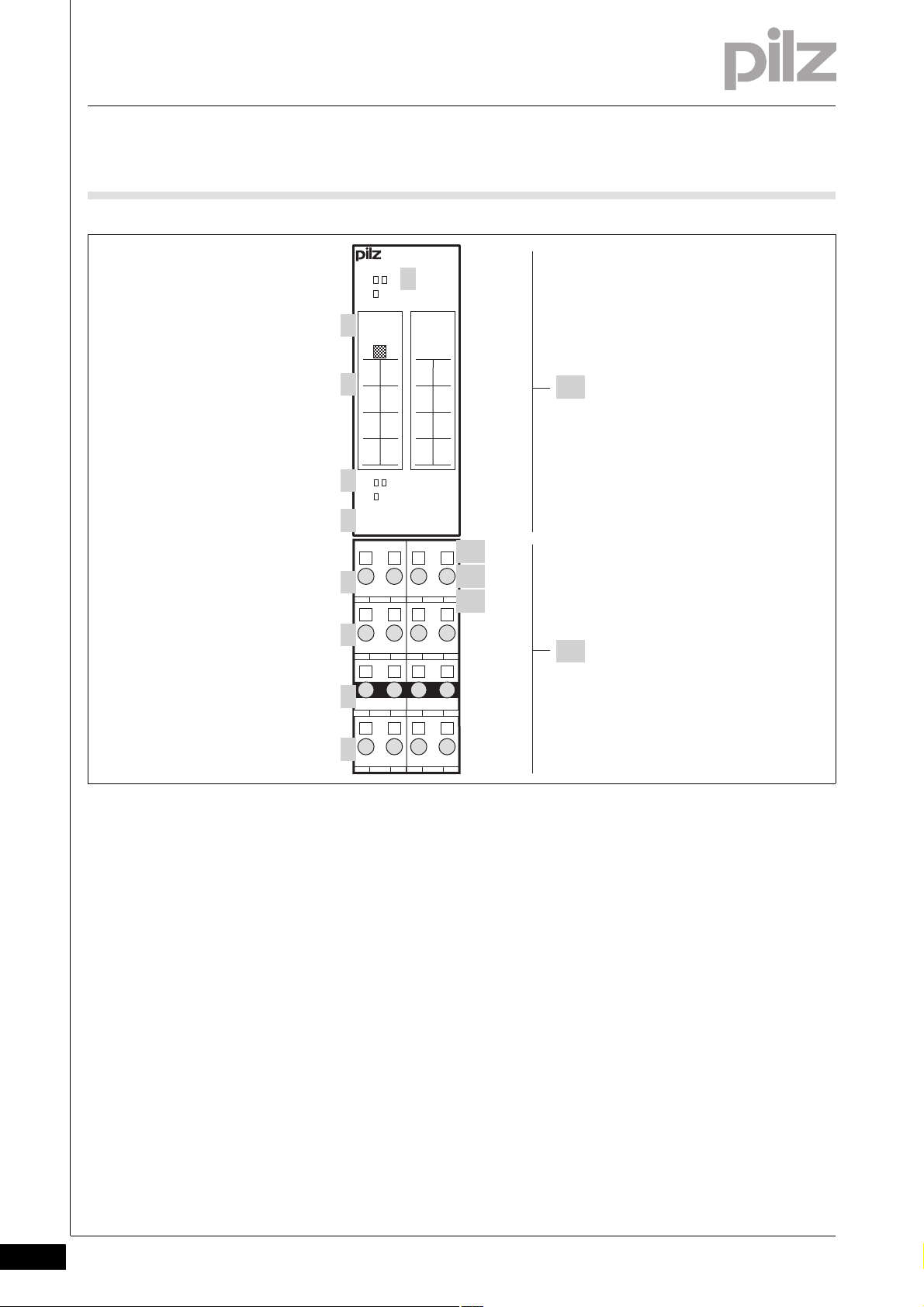
2.2 Front view
2.2Front view2200Front view2-BA_Fron tansicht
2-2
Key:
A: Electronic module
PSSu E S INC
PSSu E S INC-T
B: Base module
1: LEDs for
– Module diagnostics
– Status of the input channels A, B, C
2: Labelling strip with:
– Name of electronic module
– Order number
– Serial number
Pilz GmbH & Co. KG, Felix-Wankel-Straße 2, 73760 Ostfildern, Germany
Telephone: +49 711 3409-0, Telefax: +49 711 3409-133, E-Mail: pilz.gmbh@pilz.de
– Hardware version number
–2D code
3: Labelling strip for the terminal configuration on the base module
4: LEDs for
– Status of functional inputs G, L, S
5: Name of electronic module
Page 11

2 Overview
2.2 Front view
6: Connection level 1 (terminals 11, 21, 31, 41)
7: Connection level 2 (terminals 12, 22, 32, 42)
8: Connection level 3 (terminals 13, 23, 33, 43)
9: Connection level 4 (terminals 14, 24, 34, 44)
10: Square mounting holes (connection levels 1, 2, 3 and 4)
– With screw to loosen/tighten the screw terminal on base modules
with screw terminals
– With mechanism to operate the cage clamp on base modules with
cage clamp terminals
11: Round connection holes (connection levels 1, 2, 3 and 4) for con-
necting the signal lines
12: Mounting slot for colour marker to label the connection level (con-
nection levels 1, 2, 3 and 4)
Pilz GmbH & Co. KG, Felix-Wankel-Straße 2, 73760 Ostfildern, Germany
Telephone: +49 711 3409-0, Telefax: +49 711 3409-133, E-Mail: pilz.gmbh@pilz.de
2-3
Page 12

2 Overview
2-4
Pilz GmbH & Co. KG, Felix-Wankel-Straße 2, 73760 Ostfildern, Germany
Telephone: +49 711 3409-0, Telefax: +49 711 3409-133, E-Mail: pilz.gmbh@pilz.de
Page 13

3 Safety
3.1 Intended use
33000SafetySafety3-3.1Intended use3100Intended use3-][Gerätebe schreibung ST-Mo dule Sys A + B
][Gertebeschreibung INC
Bestimm_Verwend_ Zusatz-(T)
Bestimmung/Gertebeschreibung_Ausschluss
The module may be used for standard applications in system environment A and B.
This module may be used to connect incremental encoders with pushpull outputs to RS 422 interfaces (+/- 5 V) for standard functions.
The module PSSu E S INC-T is suitable for use where there are increased environmental requirements (see Technical Details).
Intended use includes making the electrical installation EMC-compliant.
Please refer to the guidelines stated in the "PSSuniversal Installation
Manual". The module is designed for use in an industrial environment. It
is not suitable for use in a domestic environment, as this can lead to interference.
Bestimm_Verwend_Info_PSSu_ab_1.4.0_PAS4000_ab_1.1.1
Bestimm_Verwend_B asismodule
Bestimm_Basismodule Digital breit
Bestimm_Verwend_B asismodule(-T)
The following is deemed improper use in particular:
Any component, technical or electrical modification to the module
Use of the module outside the areas described in this manual
Use of the module outside the technical details (see chapter entitled
"Technical Details")
INFORMATION
The module is supported by
PSSuniversal Configurator and PSSuniversal Assistant from
Version 1.4.0
PAS4000 from Version 1.1.1
– We recommend that you always use the latest version
(download from www.pilz.de).
The PSSu E S INC module may be used in conjunction with the following base modules:
PSSu BP 2/16S
PSSu BP 2/16C
PSSu BP-C 2/16S
PSSu BP-C 2/16C
Pilz GmbH & Co. KG, Felix-Wankel-Straße 2, 73760 Ostfildern, Germany
Telephone: +49 711 3409-0, Telefax: +49 711 3409-133, E-Mail: pilz.gmbh@pilz.de
3-1
Page 14

3 Safety
3.1 Intended use
Bestimm_Basismodule Digital-T breit
The module PSSu E S INC-T may be used in conjunction with the following base modules:
PSSu BP 2/16S-T
PSSu BP 2/16C-T
PSSu BP-C 2/16S-T
PSSu BP-C 2/16C-T
3-2
Pilz GmbH & Co. KG, Felix-Wankel-Straße 2, 73760 Ostfildern, Germany
Telephone: +49 711 3409-0, Telefax: +49 711 3409-133, E-Mail: pilz.gmbh@pilz.de
Page 15

3 Safety
3.2 Safety regulations
3.2Safety regulations3200Safety regulation s3-
3.2.1 Use of qualified personnel
Use of qualified personnel3-Sich Qualif. Personal
The products may only be assembled, installed, programmed, commissioned, operated, maintained and decommissioned by competent persons.
A competent person is someone who, because of their training, experience and current professional activity, has the specialist knowledge required to test, assess and operate the work equipment, devices,
systems, plant and machinery in accordance with the general standards
and guidelines for safety technology.
It is the company's responsibility only to employ personnel who:
Are familiar with the basic regulations concerning health and safety /
accident prevention
Have read and understood the safety guidelines given in this descrip-
tion
Have a good knowledge of the generic and specialist standards ap-
plicable to the specific application.
3.2.2 Warranty and liability
Warranty and liability3-Sich Gewhrleistung
3.2.3 Disposal
Disposal3-Si ch Entsorgung
All claims to warranty and liability will be rendered invalid if:
The product was used contrary to the purpose for which it is intended
Damage can be attributed to not having followed the guidelines in the
manual
Operating personnel are not suitably qualified
Any type of modification has been made (e.g. exchanging compo-
nents on the PCB boards, soldering work etc.).
In safety-related applications, please comply with the mission time t
M
in the safety-related characteristic data.
When decommissioning, please comply with local regulations regard-
ing the disposal of electronic devices (e.g. Electrical and Electronic
Equipment Act).
Pilz GmbH & Co. KG, Felix-Wankel-Straße 2, 73760 Ostfildern, Germany
Telephone: +49 711 3409-0, Telefax: +49 711 3409-133, E-Mail: pilz.gmbh@pilz.de
3-3
Page 16

3 Safety
3-4
Pilz GmbH & Co. KG, Felix-Wankel-Straße 2, 73760 Ostfildern, Germany
Telephone: +49 711 3409-0, Telefax: +49 711 3409-133, E-Mail: pilz.gmbh@pilz.de
Page 17

4 Function description
4.1 Module features
44000Function descriptionFunction description4-4.1Module features4100Module features4-
4.1.1 Function description
Function description4-][Funktionsbeschreibung Module Supply
Module supply
][Funktionsbeschreibung_Ein ST-INC BA Einleit
The module supply provides the module with voltage.
Inputs
3 dual-pole, differential inputs A, B, C for connecting an incremental
encoder or an encoder that provides rising edges as counter pulses.
3 single-pole inputs referenced to earth: G, L, S, for special functions
Operating modes
Incremental encoder
Counter
Functions
Period length measurement
Storing the counter status in latch memory after a latch pulse or zero
Setting the counter status
The module transfers the data and status information to the head module via the module bus. The choice of function and the function's configuration are defined via the system software.
4.1.1.1 Functional inputs (G, L, S)
Functional inputs (G, L, S) 4-][Funktionsbeschreibung_Ein ST-INC BA GLS
The single-pole inputs (G, L, S) are used for special functions. Inputs G
and L may be connected to external signal sources, e.g. to a higher order control system.
Input G (gate input)
Input L (input for latch pulse)
Input S (status input)
or
pulse
The counter is stopped with a 1 signal. The module ignores the counter pulses at the inputs until a 0 signal returns.
At a rising edge, the module stores the current counter value in the
latch memory. The counter continues counting; it is not stopped by
the latch pulse. The modul transmits the stored value to the head
module. The period length measurement may be configured as an alternative to the latch function.
The encoder's fault signal output can be connected to the status input. The module transmits the input status to the head module with
the status information.
Pilz GmbH & Co. KG, Felix-Wankel-Straße 2, 73760 Ostfildern, Germany
Telephone: +49 711 3409-0, Telefax: +49 711 3409-133, E-Mail: pilz.gmbh@pilz.de
4-1
Page 18

4 Function description
4.1 Module features
4.1.1.2 Overflow
Overflow4-][Funktionsbeschreibung_Ein ST-INC BA Zhlerstand
In both operating modes the counter can accept values from
0000 0000
With an underflow the value drops below 0000 0000
ter continues from FFFF FFFF
With an overflow the value FFFF FFFF
continues from 0000 0000
The overflow or underflow is signalled to the head module as status information.
The status information overflow is reset:
if the value again falls below 0000 0000
if 5555 0000
H
to FFFF FFFFH.
.
H
is exceeded and the counter
H
.
H
(underflow).
H
is exceeded (the lower third of the value range).
H
and the coun-
H
The status information underflow is reset:
if FFFF FFFF
if AAAA FFFF
4.1.2 Integrated protection mechanisms
Integrated protection mechanisms4-][Schutzmechanismen E/A-Module
H
H
When the PSSu E F PS1(-T) is used to supply the system, the module
supply is buffered for 20 ms if the supply voltage is interrupted.
][Schutzmechanismen ST-Module
The module detects the following errors:
Start-up error
Configuration error
ST communication error
Bus termination error
is exceeded again (overflow).
is exceeded (the upper third of the value range).
4-2
Pilz GmbH & Co. KG, Felix-Wankel-Straße 2, 73760 Ostfildern, Germany
Telephone: +49 711 3409-0, Telefax: +49 711 3409-133, E-Mail: pilz.gmbh@pilz.de
Page 19

4 Function description
C+
G
L
C-
ab cde
B+
B-
A+
A-
4.1 Module features
4.1.3 Incremental encoder operating mode
Incremental encoder operating mode4-][Funktionsbeschreibung_Ein ST-INC BA
The counter outputs and the output for the incremental encoder's zero
pulse are connected to the dual-pole inputs (A, B, C).
Inputs A, B
The first channel of the encoder is connected to input A, the second
to input B. The second channel is 90° out of phase. If channel A is
leading, the module counts forwards. If channel A is lagging, the module counts backwards (see timing diagram).
Input C
The output for the incremental encoder's zero pulse is connected to
input C. An incremental encoder typically supplies one zero pulse per
rotation. If the zero pulse function is activated, the module copies the
last value prior to the zero pulse into the latch memory and passes it
to the process image of inputs (see chapter entitled "Transfer counter
status via latch pulse").
Key:
a: The counter counts backwards because the signal at channel A is
lagging.
b: The module has received a zero pulse. Provided the function is ac-
tivated, the counter value is copied into the latch memory with a rising
edge at input C+.
c: The counter counts forwards because the signal at channel A is
leading.
d: The module has received a latch pulse. Provided the function is ac-
tivated, the counter value is copied into the latch memory with a rising
edge at input L.
][Funktionsbeschreibung_Ein ST-INC BA vielfach
Pilz GmbH & Co. KG, Felix-Wankel-Straße 2, 73760 Ostfildern, Germany
Telephone: +49 711 3409-0, Telefax: +49 711 3409-133, E-Mail: pilz.gmbh@pilz.de
e: The counter is disabled because there is a 1 signal at input G.
4-3
Page 20

4 Function description
B+
A+
2x
4x
4.1 Module features
The module can evaluate the counter pulses once, twice or four times
(configuration in the PSSu Configurator or PAS4000).
Single evaluation:
Each rising edge at channel A increases the counter status.
Double evaluation:
Each rising and each falling edge at channel A increases the counter
status.
Quadruple evaluation (default):
Each rising and each falling edge at channel A and channel B increases the counter status.
4.1.4 Counter operating mode
Counter operating mode4-][Funktionsbeschreibung_Ein ST-INC BA Zhler
In counter mode, the module's dual-pole, differential inputs A, B, C have
the following functions:
Input A (Count)
Input A is the input for the encoder's counter pulses. The module
counts each rising edge.
Input B (Up/down)
At a 0 signal the module counts forwards. At a 1 signal the module
counts backwards.
Input C (Gate/Latch)
The counter is stopped with a 1 signal. The module ignores the counter pulses at the input until a 0 signal returns.
4-4
Pilz GmbH & Co. KG, Felix-Wankel-Straße 2, 73760 Ostfildern, Germany
Telephone: +49 711 3409-0, Telefax: +49 711 3409-133, E-Mail: pilz.gmbh@pilz.de
Page 21

4 Function description
C+
G
L
ab cde
B+
A+
4.1 Module features
Key:
a: The counter counts forwards because there is 0 signal at channel
B.
b: At the next rising edge at channel A, the counter counts backwards
because there is a 1 signal at channel B.
c: The counter is disabled because there is a 1 signal at input C.
d: The module has received a latch pulse. Provided the function is ac-
tivated, the counter value is copied into the latch memory with a rising
edge at input L.
e: The counter is disabled because there is a 1 signal at input G.
4.1.5 Functions
Functions4-
4.1.5.1 Measure period length
Measure period length4-][Funktionsbeschreibung_Ein ST-INC BA Periode
The module can record the period length of the counter pulses on
channel A. The period length is the time between two rising edges at
channel A. It is transferred to the process image of inputs as multiple of
200 ns.
Prerequisite: This function is configured in the PSSu Configurator /
PAS4000.
Pilz GmbH & Co. KG, Felix-Wankel-Straße 2, 73760 Ostfildern, Germany
Telephone: +49 711 3409-0, Telefax: +49 711 3409-133, E-Mail: pilz.gmbh@pilz.de
4-5
Page 22

4 Function description
a
PAA
PAE
b c d
4.1 Module features
Key:
PIO: Bit 1 of the function call in the process image of outputs or I/O
data OutputData.LatchOrMeasure
PII: Bit 1 of the status byte in the process image of inputs or I/O data
InputData.LatchOrMeasureDone
Key to timing diagram:
Section Function Procedure for PSSu in system envi-
ronment A
a Start measurement In the user program, set Bit 1 of the
function call
b Output measured value
Set status bit
c Finish measurement In the user program, reset Bit 1 of the
d Ready for new meas-
urement
Measured value is transferred into the
process image of inputs
The module sets Bit 1 of the status byte
function call
The module resets Bit 1 of the status
byte
The result of the last period length measurement remains in the process
image of inputs until the module signals a new measurement result by
setting the status information. Before the initial measurement the process image of inputs contains 0000 0000
The module issues the result of period length measurement in multiples
of 200 ns.
Procedure for PSSu in system environment B
In the user program, set OutputData.LatchOrMeasure
Measured value is written in InputData.LatchOrPeriod
The module sets InputData.LatchOrMeasureDone
In the user program, reset OutputData.LatchOrMeasure
The module resets InputData.LatchOrMeasureDone
or FFFF FFFF
H
H
4-6
Example:
The process image of inputs contains 32
The period length is 200 ns x 50 = 10 μs
Pilz GmbH & Co. KG, Felix-Wankel-Straße 2, 73760 Ostfildern, Germany
Telephone: +49 711 3409-0, Telefax: +49 711 3409-133, E-Mail: pilz.gmbh@pilz.de
H
/50
D
Page 23

4 Function description
ab
PAA
L
PAE
c d e
4.1 Module features
4.1.5.2 Transfer counter status via latch pulse
Transfer counter status via latch pulse4-][Funktionsbeschreibung_Ein ST-INC BA Latch
A signal output can be connected to input L on the module for a latch
pulse. The latch pulse may come from a PLC or position switch, for example. Using the latch function it is possible to record and transmit the
counter status at the time of this latch pulse.
Prerequisite: This function is configured in the PSSu Configurator /
PAS4000.
Key:
PIO: Bit 1 of the byte for function calls in the process image of outputs
or I/O data OutputData.LatchOrMeasure
L: Input L for external latch
PII: Bit 1 of the status byte in the process image of inputs or I/O data
InputData.LatchOrMeasureDone
Key to timing diagram:
Section Function Procedure for PSSu in system envi-
ronment A
a Activate latch function In the user program, set Bit 1 of the
function call
b Fill latch memory Rising edge at input L: Counter status
is transferred to the latch memory
c Output counter status
Set status bit
d Finish latch function In the user program, reset Bit 1 of the
e Ready for new latch
function
Counter status is transferred to the
process image of inputs
The module sets Bit 1 of the status byte
function call
The module resets Bit 1 of the status
byte
Procedure for PSSu in system environment B
In the user program, set OutputData.LatchOrMeasure
Rising edge at input L: Counter status
is transferred to the latch memory
Counter status is written in InputData.LatchOrPeriod
The module sets InputData.LatchOrMeasureDone
In the user program, reset OutputData.LatchOrMeasure
The module resets InputData.LatchOrMeasureDone
Pilz GmbH & Co. KG, Felix-Wankel-Straße 2, 73760 Ostfildern, Germany
Telephone: +49 711 3409-0, Telefax: +49 711 3409-133, E-Mail: pilz.gmbh@pilz.de
4-7
Page 24

4 Function description
ab
PAA
C
PAE
c d e
4.1 Module features
The contents of the latch memory remains in the process image of inputs until the module signals a new memory value by setting the status
information. Before the initial transfer the process image of inputs contains 0000 0000
The module always transmits the counter status when the first latch
pulse occurs after the function has started. All subsequent latch pulses
are ignored until the function is completed and reset.
4.1.5.3 Transfer counter status via zero pulse
Transfer counter status via zero pulse4-][Funktionsbeschreibung_Ein ST-INC BA Null
The output for the incremental encoder's zero pulse is connected to input C (C+/C-). An incremental encoder typically supplies one zero pulse
per rotation. Using the zero pulse function it is possible to record the last
counter status before the zero pulse and transmit it via the process image of inputs.
or FFFF FFFF
H
H
INFORMATION
In "Counter" mode, a rising edge at input C stops the counter.
Key:
PIO: Bit 0 of the function call in the process image of outputs or I/O
data OutputData.ZeroPulseActive
C: Input C
PII: Bit 0 of the status byte in the process image of inputs or I/O data
InputData.ZeroPulse
4-8
Pilz GmbH & Co. KG, Felix-Wankel-Straße 2, 73760 Ostfildern, Germany
Telephone: +49 711 3409-0, Telefax: +49 711 3409-133, E-Mail: pilz.gmbh@pilz.de
Page 25

4 Function description
4.1 Module features
Key to timing diagram:
Section Function Procedure for PSSu in system envi-
ronment A
a Activate zero pulse
function
b Fill latch memory Rising edge at input C: Counter status
c Output counter status
Set status bit
d Finish zero pulse func-
tion
e Ready for new latch
function
In the user program, set Bit 0 of the
function call
is transferred to the latch memory
Counter status is transferred to the
process image of inputs
The module sets Bit 0 of the status byte
In the user program, reset Bit 0 of the
function call
The module resets Bit 0 of the status
byte
The zero pulse function has priority over the latch function and the "Period length measurement" function. If this function is activated, both the
other functions are ignored, even if they have been activated.
The module always transmits the counter status when the first zero
pulse occurs after the function has started. The counter statuses on all
subsequent zero pulses are ignored until the function has been completed and reset.
Procedure for PSSu in system environment B
In the user program, set OutputData.ZeroPulseActiv
Rising edge at input C: Counter status
is transferred to the latch memory
Counter status is written in InputData.LatchOrPeriod
The module sets InputData.ZeroPulse
In the user program, reset OutputData.ZeroPulseActiv
The module resets InputData.ZeroPulse
Pilz GmbH & Co. KG, Felix-Wankel-Straße 2, 73760 Ostfildern, Germany
Telephone: +49 711 3409-0, Telefax: +49 711 3409-133, E-Mail: pilz.gmbh@pilz.de
4-9
Page 26

4 Function description
b
PAA
PAE
c d ea
4.1 Module features
4.1.5.4 Set counter status
Set counter status4-][Funktionsbeschreibung_Ein ST-INC BA Zhler setzen
The "Set counter status" function sets the counter to any value. The value is stated in the user program. The module transfers the value and
continues counting from this counter status.
Key:
PIO: Bit 2 of the function call in the process image of outputs or I/O
data OutputData.SetCounter
PII: Bit 2 of the status byte in the process image of inputs or I/O data
InputData.SetCounterDone
Key to timing diagram:
Section Function Procedure for PSSu in system envi-
ronment A
a Enter counter status In the user program, write the default
counter status in the process image of
outputs
b Transfer counter status In the user program, set Bit 2 of the
function call
c Acknowledge transfer The module sets Bit 2 of the status
byte; the underflow and overflow bits
are reset
d Finish transfer In the user program, reset Bit 2 of the
function call
e Ready for new function The module resets Bit 2 of the status
byte
Procedure for PSSu in system environment B
In the user program, assign the default
counter status to OutputData.NewCounterValue
In the user program, set OutputData.SetCounter
The module sets InputData.SetCounterDone; InputData.Underflow and InputData.Overflow are reset
In the user program, reset OutputData.SetCounter
The module resets
InputData.SetCounterDone
4-10
Pilz GmbH & Co. KG, Felix-Wankel-Straße 2, 73760 Ostfildern, Germany
Telephone: +49 711 3409-0, Telefax: +49 711 3409-133, E-Mail: pilz.gmbh@pilz.de
Page 27

4 Function description
4.2 Configuration
4.2Configuration4200Configuration4-
4.2.1 Operating modes and parameters
Operating modes and parameters4-][Funktionsbeschreibung_BA_Z usatz Tabelle ST-INC
The module has the following configuration options:
Configuration Default value Key
Operating mode X Incremental encoder operating mode
Counter operating mode
Signal for gate input X Input G disables at a 1 signal.
Input G disables at a 0 signal.
Period length measurement or
latch function
Multiple evaluation X Quadruple evaluation
Status input X The status at input S is transmitted via a bit.
X Latch function
Period length measurement
Double evaluation
Single evaluation
The status is transmitted via two redundant bits.
The status is transmitted via two diverse bits.
(1)
(1)
Transmitting the status via two bits enables simple fault detection:
Two redundant bits must always be the same, two diverse bits must always be different, otherwise the transmission is faulty.
4.2.2 Input/output data
Input/output data4-
4.2.2.1 PSSu assignment in system environment A
PSSu assignment in syst em environment A4-][Funktionsbeschreibung_BA_Ein/Ausgabe INC Sys A
In the PII the module occupies
32 Bits with counter data
32 Bits with data from the latch memory or with the result from the pe-
riod length measurement
8 Bits with the status byte
In the PIO the module occupies
32 Bits with the default counter status
8 Bits with function calls
Pilz GmbH & Co. KG, Felix-Wankel-Straße 2, 73760 Ostfildern, Germany
Telephone: +49 711 3409-0, Telefax: +49 711 3409-133, E-Mail: pilz.gmbh@pilz.de
4-11
Page 28

4 Function description
4.2 Configuration
Description ST-PII bit assignment LSB
… MSB
Status byte 0 … 7 See "Status byte assign-
Current counter status 8 … 39 Measured value in incre-
Counter status from the
latch memory or result from
the period length measurement
Byte for function calls 0 … 7 See table: "Overview of
Default counter status 8 … 39 Value at which the counter
40 … 71 Value recorded after a latch
ST-PIO bit assignment
LSB … MSB
Notes
ment" table
mental encoder or counter
operating mode
or zero pulse or period
length
function calls"
is set
Overview of function calls:
Function calls Bit Assignment
Transfer counter status via zero pulse 0 0: Input C (zero pulse) inactive
1: Input C (zero pulse) active
Transfer counter status via latch pulse
or measure period length
Set counter status 2 0: Do not transfer default counter status
- 3 … 7 Reserved
(1)
1 0: Input L (latch pulse) inactive/period length measurement inactive
1: Input L (latch pulse) active/period length measurement active
1: Transfer default counter status
4-12
(1)
Whether the period length is measured or the latch pulse is evaluated,
must be defined in the PSSu Configurator or PAS4000.
Pilz GmbH & Co. KG, Felix-Wankel-Straße 2, 73760 Ostfildern, Germany
Telephone: +49 711 3409-0, Telefax: +49 711 3409-133, E-Mail: pilz.gmbh@pilz.de
Page 29

4 Function description
4.2 Configuration
Status byte assignment:
Key Bit Assignment
Zero pulse: 0 0: No zero pulse at input C
1: Zero pulse at input C
Latch pulse or period length measurement
Default counter status 2 0: Default counter status not transferred
Counter underflow 3 0: No counter underflow
Counter overflow 4 0: No counter overflow
Status input S, Bit 1 5 0: Status input, Bit 1 (message from encoder)
Status input S, Bit 2 6 0: Status input, Bit 2
Reserved 7 -
1 0: Period length or contents of latch memory not transferred
1: Period length or contents of latch memory transferred
1: Default counter status transferred
1: Counter underflow
1: Counter overflow
1: Status input, Bit 1
(1)
1: Status input, Bit 2
(1)
When configuring the module, users can determine the evaluation
method for the status input: single, redundant or diverse. Transmitting
the status via two bits enables simple fault detection: Two redundant
bits must always be the same, two diverse bits must always be different,
otherwise the transmission is faulty.
Pilz GmbH & Co. KG, Felix-Wankel-Straße 2, 73760 Ostfildern, Germany
Telephone: +49 711 3409-0, Telefax: +49 711 3409-133, E-Mail: pilz.gmbh@pilz.de
4-13
Page 30

4 Function description
4.2 Configuration
4.2.2.2 PSSu assignment in system environment B
PSSu assignment in syst em environment B4-][Funktionsbeschreibung_BA_Ein/Ausgabe ST-INC Sys B
Data access is via pre-defined I/O data types:
I/O data name I/O data type I/O data element Key
OutputData ST_O_INC ZeroPulseActiv: BOOL FALSE: Input C (zero pulse) inactive
TRUE: Input C (zero pulse) active
LatchOrMeasure: BOOL FALSE: Input L (latch pulse) inactive/period
length measurement inactive
TRUE: Input L (latch pulse) active/period length
measurement active
SetCounter: BOOL FALSE: Do not transfer default counter status
TRUE: Transfer default counter status
NewCounterValue: DWORD Default counter status
InputData ST_I_INC CurrentData: DWORD Current counter status in incremental encoder
or counter operating mode
LatchOrPeriod: DWORD Counter status after a latch or zero pulse or pe-
riod length
ZeroPulse: BOOL FALSE: No zero pulse at input C
TRUE: Zero pulse at input C
LatchOrMeasureDone:
BOOL
SetCounterDONE: BOOL FALSE: Default counter status not transferred
Underflow: BOOL FALSE: No counter underflow
Overflow: BOOL FALSE: No counter overflow
State1: BOOL FALSE: Status input, Bit 1 (message from en-
State2: BOOL FALSE: Status input, Bit 2
FALSE: Period length or contents of latch memory not transferred
TRUE: Period length or contents of latch memory transferred
TRUE: Default counter status transferred
TRUE: Counter underflow
TRUE: Counter overflow
coder)
TRUE: Status input, Bit 1
(1)
TRUE: Status input, Bit 2
4-14
(1)
When configuring the module, users can determine the evaluation
method for the status input: single, redundant or diverse. Transmitting
the status via two bits enables simple fault detection: Two redundant
bits must always be the same, two diverse bits must always be different,
otherwise the transmission is faulty.
Pilz GmbH & Co. KG, Felix-Wankel-Straße 2, 73760 Ostfildern, Germany
Telephone: +49 711 3409-0, Telefax: +49 711 3409-133, E-Mail: pilz.gmbh@pilz.de
Page 31

5 Installation
25,2 mm
76 mm
52,1 mm8,1 mm
67,7 mm
25,2 mm
56,1 mm 71,8 mm
0,8 mm
128,9 mm
72,7 mm
(2.862")
(2.992")
(2.209") (2.827")
(0.031")
5.075")
(0.992") (2.051")(0.319")
(0.992")
(2.665")
5.1 General installation guidelines
55000InstallationInstallation5-5.1General installation guidelines5100General installation guidelines5-][Montage BA E-Modul Allgemein
Montage_EMV ESD
5.1.1 Dimensions
Dimensions5-][Abmessungen 2xR
Please also refer to the PSSuniversal Installation Manual.
CAUTION!
Damage due to electrostatic discharge!
Electrostatic discharge can damage components. Ensure
against discharge before touching the product, e.g. by touching
an earthed, conductive surface or by wearing an earthed armband.
Pilz GmbH & Co. KG, Felix-Wankel-Straße 2, 73760 Ostfildern, Germany
Telephone: +49 711 3409-0, Telefax: +49 711 3409-133, E-Mail: pilz.gmbh@pilz.de
5-1
Page 32

5 Installation
[2]
[1]
[3]
5.2 Installing the base module
5.2Installing the base module5200Installing the base module5-][Montage Basismodul
Prerequisite:
The head module must be installed.
If the head module does not have an integrated power supply, a sup-
ply voltage module must be installed to the right of the head module.
Please note:
For mechanical reasons it is not possible to mix base modules with
screw terminals and base modules with cage clamp terminals.
All contacts should be protected from contamination.
The mechanics of the base modules are designed for 50 plug in/out
cycles.
Procedure:
We recommend that you wire up the base modules before inserting
the electronic modules.
Slot the groove on the base module on to the mounting rail from be-
low [1].
Push the base module back [2] until you hear it lock into position.
On the mounting rail, slide the base module to the left until you hear
the two lateral mounting hooks on the adjacent module lock into position [3].
Schematic representation:
5-2
Pilz GmbH & Co. KG, Felix-Wankel-Straße 2, 73760 Ostfildern, Germany
Telephone: +49 711 3409-0, Telefax: +49 711 3409-133, E-Mail: pilz.gmbh@pilz.de
Page 33

5 Installation
[2]
[1]
[1]
5.3 Inserting and removing an electronic module
5.3Inserting and removing an electronic module5300Inserting and removing an electronic module5-][Elektronikmodul stecken und ziehen
Please note:
Only insert on to base modules that are already installed.
Preferably these base modules should be ready wired.
Electronic modules with outputs may only be inserted and removed
when the load is switched off. Unforeseeable error reactions may be
triggered if modules are inserted and removed under load.
When an electronic module is plugged into a base module for the first
time, one part of the coding element remains on the electronic module, while its counterpart is fixed on to the base module. This is how
the base module is coded.
The mechanics of the electronic modules are designed for 50 plug in/
out cycles.
5.3.1 Inserting an electronic module
Inserting an electronic module5-][Elektronikmodul stecken
Procedure:
The electronic module must audibly lock into position [1].
Mark the electronic module using the labelling strips [2].
Schematic representation:
Pilz GmbH & Co. KG, Felix-Wankel-Straße 2, 73760 Ostfildern, Germany
Telephone: +49 711 3409-0, Telefax: +49 711 3409-133, E-Mail: pilz.gmbh@pilz.de
5-3
Page 34

5 Installation
[1]
[2]
[1]
5.3 Inserting and removing an electronic module
5.3.2 Removing an electronic module
Removing an electronic module5-][Elektronikmodul ziehen
Procedure:
Press the locking mechanisms [1] together simultaneously.
Pull out the electronic module [2].
Schematic representation:
5-4
5.3.3 Changing an electronic module during operation
Changing an electronic module during operation5-][Montage BA Hot Swapping ST-E/A-Modul
The electronic module can be hot swapped. The configuration data is retained when a module is swapped.
Effects:
System environment A:
– An ST communication error may occur.
System environment B:
– While the module is disconnected, the substitute values for the
module's signals/values are used (Valid Bits = FALSE).
– Once the module is reconnected, it is reactivated automatically.
Pilz GmbH & Co. KG, Felix-Wankel-Straße 2, 73760 Ostfildern, Germany
Telephone: +49 711 3409-0, Telefax: +49 711 3409-133, E-Mail: pilz.gmbh@pilz.de
Page 35

6 Wiring
6.1 General wiring guidelines
66000WiringWiring6-6.1General wiring g uidelines6100Ge neral wiring guidelin es6-][Verdrahtung BA Einleitung
][Verdrahtung ST INC
][Verdrahtung Zusatz mit C
Please note:
The module's connections are galvanically isolated from the module
supply and periphery supply.
For EMC reasons we recommend that you operate inputs A, B, C ex-
clusively as differential inputs with inverted signals (A+/A-, B+/B-, C+/
C-).
The module evaluates open differential inputs (A+/A-, B+/B-, C+/C-)
as a 1 signal.
The module evaluates open function inputs (G, L, S) as a 0 signal.
Use twisted pair cables to carry the inverted signals. This will increase
the noise immunity.
Use shielded signal cables with metallic plugs.
On base modules with C-rail:
– Connect the shield to the terminals on the C-rail.
– Connect the C-rail with low impedance to the functional earth.
On base modules without C-rail:
– Connect the shield as shown in the terminal configuration section.
– The module connects the shield to the functional earth via the
mounting rail.
The channel for the incremental encoder's zero pulse has a different
designation depending on the manufacturer (N, C, Z, 0,...)
The supply voltages must be extra low voltages with safe electrical
separation (PELV or SELV) in accordance with VDE 0100, Part 410.
Use copper wiring.
The terminal configuration as stated on the front plate applies for base
modules with C-rail. The terminal configuration as stated in the technical documentation applies for all other base modules.
Pilz GmbH & Co. KG, Felix-Wankel-Straße 2, 73760 Ostfildern, Germany
Telephone: +49 711 3409-0, Telefax: +49 711 3409-133, E-Mail: pilz.gmbh@pilz.de
6-1
Page 36

6 Wiring
DIN 5264-A
2111
[1]
[3]
[2]
[4]
[5]
[6]
6.1 General wiring guidelines
6.1.1 Mechanical connection of the base modules
Mechanical connection of the base modules6-][Modulverdrahtung mech
Procedure:
Use a flat blade screwdriver (DIN 5264-A)!
Strip the wire back 8 mm.
If necessary, label the connection level with a colour marker [3].
Base module with screw terminals:
– Use a screwdriver to loosen the screw on the screw terminal [1]
– Insert the stripped cable into the round fixing hole [2], as far as it
will go.
– Tighten up the screw on the screw terminal.
– Check that the cable is firmly seated.
Base module with cage clamp terminals:
– Insert the screwdriver [4] into the square hole [1].
– Insert the stripped cable into the round fixing hole [2], as far as it
will go [5].
– Pull out the screwdriver [6].
– Check that the cable is firmly seated.
6-2
][Modulverdrahtung el Sys A + B
Pilz GmbH & Co. KG, Felix-Wankel-Straße 2, 73760 Ostfildern, Germany
Telephone: +49 711 3409-0, Telefax: +49 711 3409-133, E-Mail: pilz.gmbh@pilz.de
Page 37

6 Wiring
6.1 General wiring guidelines
Please note:
The minimum cable cross section for field connection terminals on the
base modules is 0.14 mm
The maximum cable cross section for field connection terminals is:
– Digital inputs: 1.5 mm
– Digital outputs: 2.0 mm
– Inputs/outputs on the counter modules: 1.5 mm
– Analogue inputs/outputs: 1.5 mm
– Communication cables: 1.5 mm
– Test pulse outputs: 1.5 mm
– Power supply: 2.5 mm
– Functional earth: 2.5 mm
On base modules with screw terminals:
– If you use a multi-strand cable to connect the I/Os, it is recom-
mended that you use ferrules conforming to Parts 1 and 2 of
DIN 46228, 0.14 ... 1.5 mm
sential. To crimp the ferrules you can use crimp pliers (crimp form
A or C) conforming to EN 60947-1, such as the PZ 1.5 or PZ 6.5
from Weidmüller, for example.
– Maximum torque setting: 0.8 Nm
Use copper wiring.
2
(AWG26)
2
(AWG16)
2
(AWG14)
2
(AWG16)
2
(AWG16)
2
(AWG16)
2
(AWG16)
2
(AWG12)
2
(AWG12)
2
, Form A or C, although this is not es-
Pilz GmbH & Co. KG, Felix-Wankel-Straße 2, 73760 Ostfildern, Germany
Telephone: +49 711 3409-0, Telefax: +49 711 3409-133, E-Mail: pilz.gmbh@pilz.de
6-3
Page 38

6 Wiring
2111
2212
2313
2414
4131
4232
4333
4434
2111
2212
2313
2414
4131
4232
4333
4434
6.2 Terminal configuration
6.2Terminal configuration6200Terminal configuration6-][Klemmenbelegung ST INC
Base module Terminal configuration
Screw terminals:
PSSu BP 2/16S
PSSu BP 2/16S-T
Without C-rail:
11: Input A+
Cage clamp terminals:
PSSu BP 2/16C
PSSu BP 2/16C-T
Screw terminals:
PSSu BP-C 2/16S
PSSu BP-C 2/16S-T
21: Input B+
31: Input C+
41: Input G (Gate)
12-22: 0 V counter
(12-22 linked within the base module)
32-42: Input S (Status)
(32-42 linked within the base module)
13-23-33-43: Shield connection
(13-23, 33-43 linked within the base
module)
14: Input A-
24: Input B-
34: Input C-
44: Input L (Latch)
With C-rail:
11: Input A+
Cage clamp terminals:
21: Input B+
PSSu BP-C 2/16C
PSSu BP-C 2/16C-T
31: Input C+
41: Input G (Gate)
12-22: 0 V counter
(12-22 linked within the base module)
32-42: Input S (Status)
(32-42 linked within the base module)
13-23-33-43: C-rail supply
Shield connection
(13-23, 33-43 linked within the base
module)
14: Input A-
24: Input B-
34: Input C-
44: Input L (Latch)
6-4
Pilz GmbH & Co. KG, Felix-Wankel-Straße 2, 73760 Ostfildern, Germany
Telephone: +49 711 3409-0, Telefax: +49 711 3409-133, E-Mail: pilz.gmbh@pilz.de
Page 39

6 Wiring
2111
2212
2313
2414
4131
4232
4333
4434
Gate
C+
CB-
Status
A-
B+
A+
Latch
0 V
2111
2212
2313
2414
4131
4232
4333
4434
Gate
C+
CB-
Status
A-
B+
A+
Latch
0 V
6.3 Connecting the module
6.3Connecting the module6300Connecting the module6-][Anschluss IN C
Incremental encoder operating mode
Encoder supply via the
PSSu E PD module
With C-rail
Incremental encoder operating mode
Encoder supply via the
PSSu E PD module
Without C-rail
Pilz GmbH & Co. KG, Felix-Wankel-Straße 2, 73760 Ostfildern, Germany
Telephone: +49 711 3409-0, Telefax: +49 711 3409-133, E-Mail: pilz.gmbh@pilz.de
6-5
Page 40

6 Wiring
2111
2212
2313
2414
4131
4232
4333
4434
C+ (Gate)
B+ (Up/Down)
CBA-
A+ (Count)
0 V
2111
2212
2313
2414
4131
4232
4333
4434
C+ (Gate)
B+ (Up/Down)
CBA-
A+ (Count)
0 V
6.3 Connecting the module
Counter operating mode With C-rail
Encoder supply via the
PSSu E PD module
Functional inputs (G, L, S) not
connected.
Counter operating mode Without C-rail
Encoder supply via the
PSSu E PD module
Functional inputs (G, L, S) not
connected.
6-6
Pilz GmbH & Co. KG, Felix-Wankel-Straße 2, 73760 Ostfildern, Germany
Telephone: +49 711 3409-0, Telefax: +49 711 3409-133, E-Mail: pilz.gmbh@pilz.de
Page 41

7 Operation
7.1 Messages
77000OperationOperation7-7.1Messages71 00Messages7-][BA_Betrieb Störung LED "Err" Sys A + B
A module error is displayed via the "Err" LED (see section entitled "Dis-
play elements"), signalled to the head module and then entered in the
head module's
Error stack, with PSSu in system environment A
][BA_Betrieb Fehler ST-Zhle r
Module error Explanation Remedy
Start-up error Error as the PSSu system starts up Change faulty module.
Configuration error Incorrect module type configured. The configured hardware registry does
ST communication error Error during ST communication Change faulty module.
Bus termination error There is no terminating plate or there is
Diagnostic log, with PSSu in system environment B.
The module can detect the following errors:
not match the actual hardware registry.
Install a terminating plate with inte-
a bad contact with the module bus.
grated end bracket or insert the base
modules together correctly.
Pilz GmbH & Co. KG, Felix-Wankel-Straße 2, 73760 Ostfildern, Germany
Telephone: +49 711 3409-0, Telefax: +49 711 3409-133, E-Mail: pilz.gmbh@pilz.de
7-1
Page 42

7 Operation
Err
11I021
I1
Err
7.2 Display elements
7.2Display elements7200Display elements7-Anzeige Legende 2x
Key:
LED on
LED off
7.2.1 Display elements for module diagnostics
Display elements for module diagnostics7-][BA_Anzeige LED Err
The module has an LED for displaying module errors (“Err” LED).
LED Key
Name Colour Status
Err - - - No error
red Module error
7-2
Pilz GmbH & Co. KG, Felix-Wankel-Straße 2, 73760 Ostfildern, Germany
Telephone: +49 711 3409-0, Telefax: +49 711 3409-133, E-Mail: pilz.gmbh@pilz.de
Page 43

7 Operation
Err
11O021 31O141
A
B
A
Err
B
C
C
G
S
Err
11
A+
120V22
0V
13
(C)23(C)
32S42
S
33
(C)43(C)
G
S
A
B
C
L
21
B+
14A-24
B-
41C+41
G
34C-44
L
L
7.2 Display elements
7.2.2 Display elements for counter status
Display elements for counter status7-BA_Anzeige
The module has three LEDs for the status of the counter inputs (LEDs
"A", "B" and "C").
LED Key
Name Colour Status Signal
A - - - 0 signal at counter input A
B - - - 0 signal at counter input B
green 1 signal at counter input A
green 1 signal at counter input B
C - - - 0 signal at counter input C
green 1 signal at counter input C
7.2.3 Display elements for status of the functional inputs
Display elements for status of the functional inputs7-BA_Anzeige
The module has three LEDs for the status of the functional inputs (LEDs
"G", "L" and "S").
LED Key
Name Colour Status Signal
G - - - 0 signal at functional input G
green 1 signal at functional input G
L - - - 0 signal at functional input L
green 1 signal at functional input L
S - - - 0 signal at functional input S
green 1 signal at functional input S
Pilz GmbH & Co. KG, Felix-Wankel-Straße 2, 73760 Ostfildern, Germany
Telephone: +49 711 3409-0, Telefax: +49 711 3409-133, E-Mail: pilz.gmbh@pilz.de
7-3
Page 44

7 Operation
7.3 Status information
7.3Status information7300Status information7-][BA_Betrieb Querverweis Sys A + B
The way in which status information is assigned to the status byte and
I/O data is described in the chapter entitled "Function Description", under "Input/output data".
7-4
Pilz GmbH & Co. KG, Felix-Wankel-Straße 2, 73760 Ostfildern, Germany
Telephone: +49 711 3409-0, Telefax: +49 711 3409-133, E-Mail: pilz.gmbh@pilz.de
Page 45

8 Technical details
8.1 Technical details
88000Technical detailsTechnical details8-8.1Technical details8100Technical details8-][Technische Daten PSSu ST-Zähler
Technical details
Application range Standard
Module's device code 0321h
Number of ST input bits 64
Number of ST output bits 32
Number of ST status bits 8
Number of ST control bits 8
Support in system environment A
from ST firmware version for other head modules 11
from ST firmware version PSSu H S PN 2
from ST firmware version PSSu WR S IDN 4
Support in system environment B
from head module ST firmware version 1.0.0
Electrical data
Internal supply voltage (module supply)
Supply voltage range of module supply 4.8 - 5.4 V
Module's current consumption 157 mA
Module's power consumption 0.79 W
Periphery's supply voltage (periphery supply)
Voltage range 16.8 - 30.0 V
Module's current consumption with no load 15 mA
Module's power consumption with no load 0.37 W
Max. power dissipation of the module 1.20 W
Counter interface
Number of counter inputs 1
Type of counter inputs Incremental encoder
Max. number of bits on the counter input 32 Bit
Evaluation of counter pulses 1x, 2x, 4x
Maximum threshold frequency 5.0 MHz
Phase offset between differential signals A and B 90 deg
Phase offset tolerance 30 deg
Signal at counter inputs A and B and/or C Differential signal (RS 422)
Time constant of input filter on LATCH signal 50 µs
Time constant of input filter on GATE signal 50 µs
Time constant of input filter on STATUS signal 50 µs
Permitted low signal range on LATCH/GATE/STATUS sig-
nals
Permitted high signal range on LATCH/GATE/STATUS signals
Typ. input current of the LATCH and/or GATE and/or STA-
TUS signals at low level
Typ. input current of the LATCH and/or GATE and/or STA-
TUS signals at high level
Potential isolation between input/output and periphery
supply
Potential isolation between input/output and voltage for
the internal module bus
Typ. processing time 0.1 ms
-3 - 5 V
11 - 30 V
0 mA
4.0 mA
yes
yes
Pilz GmbH & Co. KG, Felix-Wankel-Straße 2, 73760 Ostfildern, Germany
Telephone: +49 711 3409-0, Telefax: +49 711 3409-133, E-Mail: pilz.gmbh@pilz.de
8-1
Page 46

8 Technical details
8.1 Technical details
Environmental data
Climatic suitability EN 60068-2-14, EN 60068-2-1, EN 60068-2-2,
EN 60068-2-30, EN 60068-2-78
Ambient temperature in accordance with EN 60068-2-14 0 - 60 °C
-40 - 70 °C coated version (-T)
Storage temperature in accordance with EN 60068-2-1/-2 -25 - 70 °C
-40 - 70 °C coated version (-T)
Climatic suitability in accordance with EN 60068-2-30,
EN 60068-2-78
Condensation no
Max. operating height above sea level 2000 m
EMC EN 61000-4-2, EN 61000-4-3, EN 61000-4-4,
Vibration to EN 60068-2-6
Frequency 10 - 150 Hz
Max. acceleration 1g
Shock stress
EN 60068-2-27 15g
EN 60068-2-29 10g
Protection type in accordance with EN 60529
Mounting (e.g. cabinet) IP54
Housing IP20
Terminals IP20
Airgap creepage in accordance with EN 60664-1
Overvoltage category II
Pollution degree 2
Mechanical data
Housing material
Front PC
Bottom PC
Coding PA
Dimensions
Height 76.0 mm
Width 25.4 mm
Depth 60.2 mm
Weight 50 g
Mechanical coding
Type F
Colour dark grey
Technische Daten_Satz No rmen
93 % r. h. at 40 °C
yes coated version (-T)
5000 m coated version (-T)
EN 61000-4-5, EN 61000-4-6, EN 61000-6-2,
EN 61000-6-4
10 - 1,000 Hz coated version (-T)
5g coated version (-T)
11 ms
25g coated version (-T)
16 ms
6 ms coated version (-T)
52 g coated version (-T)
8-2
The standards current on 2005-04 apply.
Pilz GmbH & Co. KG, Felix-Wankel-Straße 2, 73760 Ostfildern, Germany
Telephone: +49 711 3409-0, Telefax: +49 711 3409-133, E-Mail: pilz.gmbh@pilz.de
Page 47

8 Technical details
8.2 Order reference
8.2Order reference8200Order reference8-Bestel ldaten
Order reference
Description Order no.
PSSu E S INC
(Electronic module)
PSSu E S INC-T
(Electronic module, coated version)
][Bestelldaten Basismodule Digital breit mit -T
Base modules Order no.
PSSu BP 2/16S
(Base module without C-rail with screw terminals)
PSSu BP 2/16S-T
(Base module without C-rail with screw terminals, coated
version)
PSSu BP 2/16C
(Base module without C-rail with cage clamp terminals)
PSSu BP 2/16C-T
(Base module without C-rail with cage clamp terminals,
coated version)
PSSu BP-C 2/16S
(Base module with C-rail and screw terminals)
PSSu BP-C 2/16S-T
(Base module with C-rail and screw terminals, coated version)
PSSu BP-C 2/16C
(Base module with C-rail and cage clamp terminals)
PSSu BP-C 2/16C-T
(Base module with C-rail and cage clamp terminals, coated
version)
312 485
314 485
312 628
314 628
312 629
314 629
312 630
314 630
312 631
314 631
Pilz GmbH & Co. KG, Felix-Wankel-Straße 2, 73760 Ostfildern, Germany
Telephone: +49 711 3409-0, Telefax: +49 711 3409-133, E-Mail: pilz.gmbh@pilz.de
8-3
Page 48

8 Technical details
8-4
Pilz GmbH & Co. KG, Felix-Wankel-Straße 2, 73760 Ostfildern, Germany
Telephone: +49 711 3409-0, Telefax: +49 711 3409-133, E-Mail: pilz.gmbh@pilz.de
Page 49

...
21447-EN-03, 2011-04 Printed in Germany
© Pilz GmbH & Co. KG, 2011
+49 711 3409-444
support@pilz.com
Pilz GmbH & Co. KG
Felix-Wankel-Straße 2
73760 Ostfildern, Germany
Telephone: +49 711 3409-0
Telefax: +49 711 3409-133
E-Mail: pilz.gmbh@pilz.de
Internet: www.pilz.com
Technical support
In many countries we are
represented by our subsidiaries
and sales partners.
Please refer to our homepage
for further details or contact our
headquarters.
InduraNET p
®
, Pilz
®
, PIT
®
, PMCprotego
®
, PMI
®
, PNOZ
®
, Primo
®
, PSEN
®
, PSS
®
, PVIS
®
, SafetyBUS p
®
, SafetyEYE
®
, SafetyNET p
®
, the spirit of safety
®
are registered and protected trademarks
of Pilz GmbH & Co. KG in some countries. We would point out that product features may vary from the details stated in this document, depending on the status at the time of publication and the scope
of the equipment. We accept no responsibility for the validity, accuracy and entirety of the text and graphics presented in this information. Please contact our Technical Support if you have any questions.
Contact address
 Loading...