

Page 1

Operating Manual PSSu E S ABS SSI(- T)
Operating Manual PSSu E S ABS SSI(-T)
PSSu E S ABS SSI(-T)
Decentralised system PSSuniversal I/O
Operating Manual — No. 21441-EN-03
Page 2

This document is a translation of the original document.
All rights to this documentation are reserved by Pilz GmbH & Co. KG. Copies may be made
for internal purposes.
Suggestions and comments for improving this documentation will be gratefully received.
Pilz®, PIT®, PMI®, PNOZ®, Primo®, PSEN®, PSS®, PVIS®, SafetyBUS p®, SafetyEYE®,
SafetyNET p®, the spirit of safety® are registered and protected trademarks of
Pilz GmbH & Co. KG in some countries.
SD means Secure Digital.
Preface
Page 3

Contents
Contents
Contents Page
Chapter 1 Introduction
1.1 Validity of documentation 1-1
1.1.1 Retaining the documentation 1-1
1.1.2 Terminology: System environment A and B 1-1
1.2 Overview of documentation 1-2
1.3 Definition of symbols 1-3
Chapter 2 Overview
2.1 Module structure 2-1
2.1.1 Module features 2-1
2.2 Front view 2-2
Chapter 3 Safety
3.1 Intended use 3-1
3.2 Safety regulations 3-3
3.2.1 Use of qualified personnel 3-3
3.2.2 Warranty and liability 3-3
3.2.3 Disposal 3-3
Chapter 4 Function description
4.1 Module features 4-1
4.1.1 Functions 4-1
4.1.2 Integrated protection mechanisms 4-2
4.2 Configuration 4-3
4.2.1 Parameter 4-3
4.2.2 Input/output data 4-4
4.2.2.1 PSSu assignment in system environment A 4-4
4.2.2.2 PSSu assignment in system environment B4-5
Chapter 5 Installation
5.1 General installation guidelines 5-1
5.1.1 Dimensions 5-1
5.2 Installing the base module 5-3
5.3 Inserting and removing an electronic
module
5.3.1 Inserting an electronic module 5-4
5.3.2 Removing an electronic module 5-5
5.3.3 Changing an electronic module during
operation
5-4
5-5
Pilz GmbH & Co. KG, Felix-Wankel-Straße 2, 73760 Ostfildern, Germany
Telephone: +49 711 3409-0, Telefax: +49 711 3409-133, E-Mail: pilz.gmbh@pilz.de
1
Page 4
Contents
Chapter 6 Wiring
6.1 General wiring guidelines 6-1
6.1.1 Mechanical connection of the base
6.2 Terminal configuration 6-4
6.3 Connecting the module 6-5
Chapter 7 Operation
7.1 Messages 7-1
7.2 Display elements 7-2
7.2.1 Display elements for module diagnostics 7-2
7.2.2 Display elements for counter status 7-2
7.3 Status information 7-3
6-1
modules
Chapter 8 Technical details
8.1 Technical details 8-1
8.2 Order reference 8-3
Pilz GmbH & Co. KG, Felix-Wankel-Straße 2, 73760 Ostfildern, Germany
2
Telephone: +49 711 3409-0, Telefax: +49 711 3409-133, E-Mail: pilz.gmbh@pilz.de
Page 5

1 Introduction
1.1 Validity of documentation
11000IntroductionIntroduction1-1.1Validity of docume ntation1100Validity of documenta tion1-][BA Einf Gültigkeit_(T)
This documentation is valid for the products PSSu E S ABS SSI and
Einf Einleitung
Bestimm_Verwend_ Zusatz-(T)
1.1.1 Retaining the documentation
Retaining the documentation1-Einf Aufbewahren
PSSu E S ABS SSI-T. It is valid until new documentation is published.
This operating manual explains the function and operation, describes
the installation and provides guidelines on how to connect the product .
The module PSSu E S ABS SSI-T is suitable for use where there are increased environmental requirements (see Technical Details).
This documentation is intended for instruction and should be retained
for future reference.
1.1.2 Terminology: System environment A and B
Terminology: System environment A and B1-][BA Einf Begriffsdefinition Sys A + B
The PSSu system can be used in two different system environments.
The module's application area is described in the chapter "Intended
Use" of the manual.
The distinction is made between
PSSu in system environment A
PSSu in system environment B
The distinction is based on the application area of the PSSu system.
PSSu in system environment A may be used in the
Decentralised system PSSu I/O with SafetyBUS p
Decentralised system PSSu I/O with ST fieldbuses such as CANopen,
DeviceNet
Not in the automation system PSS 4000
PSSu in system environment B may be used in the
Automation system PSS 4000, e.g. with the
– Decentralised system PSSu I/O with SafetyNET p
– Control system PSSu PLC
– Control system PSSu multi
Pilz GmbH & Co. KG, Felix-Wankel-Straße 2, 73760 Ostfildern, Germany
Telephone: +49 711 3409-0, Telefax: +49 711 3409-133, E-Mail: pilz.gmbh@pilz.de
1-1
Page 6

1 Introduction
1.2 Overview of documentation
1.2Overview of documentation1200Overview of documentation1-][BA Einf Übersicht E-Modul
1 Introduction
The introduction is designed to familiarise you with the contents, structure and specific order of this manual.
2 Overview
This chapter provides information on the product's most important features.
3 Safety
This chapter must be read as it contains important information on safety
and intended use.
4 Function Description
This chapter describes the product's individual components.
5 Installation
This chapter explains how to install the product.
6 Wiring
This chapter describes the product's wiring.
7 Operation
This chapter explains the display elements and advises on what to do if
a fault occurs.
8 Technical Details
This chapter contains the product's technical details and order reference.
1-2
Pilz GmbH & Co. KG, Felix-Wankel-Straße 2, 73760 Ostfildern, Germany
Telephone: +49 711 3409-0, Telefax: +49 711 3409-133, E-Mail: pilz.gmbh@pilz.de
Page 7
1 Introduction
1.3 Definition of symbols
1.3Definition of symbols1300Definition of symbols1-Einfhrung Zeichen
Information that is particularly important is identified as follows:
DANGER!
This warning must be heeded! It warns of a hazardous situation
that poses an immediate threat of serious injury and death and
indicates preventive measures that can be taken.
WARNING!
This warning must be heeded! It warns of a hazardous situation
that could lead to serious injury and death and indicates preventive measures that can be taken.
CAUTION!
This refers to a hazard that can lead to a less serious or minor
injury plus material damage, and also provides information on
preventive measures that can be taken.
NOTICE
This describes a situation in which the unit(s) could be damaged
and also provides information on preventive measures that can
be taken. It also highlights areas within the text that are of particular importance.
INFORMATION
This gives advice on applications and provides information on
special features.
Pilz GmbH & Co. KG, Felix-Wankel-Straße 2, 73760 Ostfildern, Germany
Telephone: +49 711 3409-0, Telefax: +49 711 3409-133, E-Mail: pilz.gmbh@pilz.de
1-3
Page 8

1 Introduction
1-4
Pilz GmbH & Co. KG, Felix-Wankel-Straße 2, 73760 Ostfildern, Germany
Telephone: +49 711 3409-0, Telefax: +49 711 3409-133, E-Mail: pilz.gmbh@pilz.de
Page 9

2 Overview
2.1 Module structure
22000OverviewOverview2-2.1Module structure2100Module structure2-][BA Übersicht Aufbau
A module consists of
Electronic module and
Base module with
The base modules are the carrier units for the electronic modules and
are used to connect the field wiring. The electronic modules are inserted
on to the base modules and determine the module's function.
Details of the base modules that can be used are available in the chapter
entitled “Intended Use”.
– Screw terminals or
– Cage clamp terminals
2.1.1 Module features
Module features2-Geraetemerkmale_Zusatz BA Einleitung
][Merkmale_Ein_Aus ABS SS I
][Merkmale_LED ABS SSI
][Merkmale_Zusatz ST-Module Sys A + B
][Geraetemerkmal_T
The product has the following features:
Counter input (data)
– Input data length up to max. 32 Bit
– Differential input
Test pulse output (clock) for requesting data
– Differential output
Transmission rate up to max. 1.5 MHz
LED-Anzeigen für:
– Data transfer
– Module error
For standard applications in system environment A and B
Coated version of the module:
PSSu E S ABS SSI-T: for increased environmental requirements
Pilz GmbH & Co. KG, Felix-Wankel-Straße 2, 73760 Ostfildern, Germany
Telephone: +49 711 3409-0, Telefax: +49 711 3409-133, E-Mail: pilz.gmbh@pilz.de
2-1
Page 10
2 Overview
2111
2212
2313
2414
Err
PSSu E S
ABS SSI
I 0
11D+21
CI+
120V22
0V
13 23
14D-24
CI-
PSSu E S
ABS SSI
312480
000000
001
(C) (C)
1
3
8
7
4
5
6
9
10
2
11
A
B
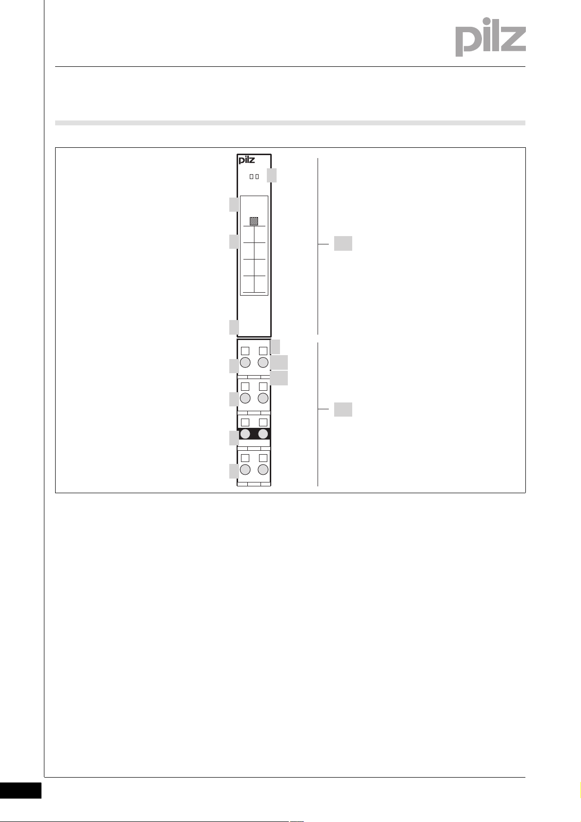
2.2 Front view
2.2Front view2200Front view2-BA_Fron tansicht
2-2
Key:
A: Electronic module
PSSu E S ABS SSI
PSSu E S ABS SSI-T
B: Base module
1: LEDs for
– Module diagnostics
– Status of the data transfer
2: Labelling strip with:
– Name of electronic module
– Order number
– Serial number
Pilz GmbH & Co. KG, Felix-Wankel-Straße 2, 73760 Ostfildern, Germany
Telephone: +49 711 3409-0, Telefax: +49 711 3409-133, E-Mail: pilz.gmbh@pilz.de
– Hardware version number
–2D code
3: Labelling strip for the terminal configuration on the base module
4: Name of electronic module
5: Connection level 1 (terminals 11, 21)
6: Connection level 2 (terminals 12, 22)
Page 11

2 Overview
2.2 Front view
7: Connection level 3 (terminals 13, 23)
8: Connection level 4 (terminals 14, 24)
9: Square mounting holes (connection levels 1, 2, 3 and 4)
– With screw to loosen/tighten the screw terminal on base modules
with screw terminals
– With mechanism to operate the cage clamp on base modules with
cage clamp terminals
10: Round connection holes (connection levels 1, 2, 3 and 4) for con-
necting the signal lines
11: Mounting slot for colour marker to label the connection level (con-
nection levels 1, 2, 3 and 4)
Pilz GmbH & Co. KG, Felix-Wankel-Straße 2, 73760 Ostfildern, Germany
Telephone: +49 711 3409-0, Telefax: +49 711 3409-133, E-Mail: pilz.gmbh@pilz.de
2-3
Page 12

2 Overview
2-4
Pilz GmbH & Co. KG, Felix-Wankel-Straße 2, 73760 Ostfildern, Germany
Telephone: +49 711 3409-0, Telefax: +49 711 3409-133, E-Mail: pilz.gmbh@pilz.de
Page 13
3 Safety
3.1 Intended use
33000SafetySafety3-3.1Intended use3100Intended use3-][Gerätebe schreibung ST-Mo dule Sys A + B
][Gertebeschreibung ABS SSI
Bestimm_Verwend_ Zusatz-(T)
Bestimmung/Gertebeschreibung_Ausschluss
The module may be used for standard applications in system environment A and B.
This module can be used to connect SSI absolute encoders (synchronous serial interface) for standard functions.
The module PSSu E S ABS SSI-T is suitable for use where there are increased environmental requirements (see Technical Details).
Intended use includes making the electrical installation EMC-compliant.
Please refer to the guidelines stated in the "PSSuniversal Installation
Manual". The module is designed for use in an industrial environment. It
is not suitable for use in a domestic environment, as this can lead to interference.
Bestimm_Verwend_Info_PSSu_ab_1.4.0_PAS4000_ab_1.1.1
Bestimm_Verwend_B asismodule
Bestimm_Basismodule Digital schmal
Bestimm_Verwend_B asismodule(-T)
The following is deemed improper use in particular:
Any component, technical or electrical modification to the module
Use of the module outside the areas described in this manual
Use of the module outside the technical details (see chapter entitled
"Technical Details")
INFORMATION
The module is supported by
PSSuniversal Configurator and PSSuniversal Assistant from
Version 1.4.0
PAS4000 from Version 1.1.1
– We recommend that you always use the latest version
(download from www.pilz.de).
The PSSu E S ABS SSI module may be used in conjunction with the following base modules:
PSSu BP 1/8S
PSSu BP 1/8C
PSSu BP-C 1/8S
PSSu BP-C 1/8C
PSSu BP 1/12S
PSSu BP 1/12C
PSSu BP-C1 1/12S
PSSu BP-C1 1/12C
Pilz GmbH & Co. KG, Felix-Wankel-Straße 2, 73760 Ostfildern, Germany
Telephone: +49 711 3409-0, Telefax: +49 711 3409-133, E-Mail: pilz.gmbh@pilz.de
3-1
Page 14

3 Safety
3.1 Intended use
Bestimm_Basismodule Digital-T schmal
The module PSSu E S ABS SSI-T may be used in conjunction with the
following base modules:
PSSu BP 1/8S-T
PSSu BP 1/8C-T
PSSu BP-C 1/8S-T
PSSu BP-C 1/8C-T
PSSu BP 1/12S-T
PSSu BP 1/12C-T
PSSu BP-C1 1/12S-T
PSSu BP-C1 1/12C-T
3-2
Pilz GmbH & Co. KG, Felix-Wankel-Straße 2, 73760 Ostfildern, Germany
Telephone: +49 711 3409-0, Telefax: +49 711 3409-133, E-Mail: pilz.gmbh@pilz.de
Page 15

3 Safety
3.2 Safety regulations
3.2Safety regulations3200Safety regulation s3-
3.2.1 Use of qualified personnel
Use of qualified personnel3-Sich Qualif. Personal
The products may only be assembled, installed, programmed, commissioned, operated, maintained and decommissioned by competent persons.
A competent person is someone who, because of their training, experience and current professional activity, has the specialist knowledge required to test, assess and operate the work equipment, devices,
systems, plant and machinery in accordance with the general standards
and guidelines for safety technology.
It is the company's responsibility only to employ personnel who:
Are familiar with the basic regulations concerning health and safety /
accident prevention
Have read and understood the safety guidelines given in this descrip-
tion
Have a good knowledge of the generic and specialist standards ap-
plicable to the specific application.
3.2.2 Warranty and liability
Warranty and liability3-Sich Gewhrleistung
3.2.3 Disposal
Disposal3-Si ch Entsorgung
All claims to warranty and liability will be rendered invalid if:
The product was used contrary to the purpose for which it is intended
Damage can be attributed to not having followed the guidelines in the
manual
Operating personnel are not suitably qualified
Any type of modification has been made (e.g. exchanging compo-
nents on the PCB boards, soldering work etc.).
In safety-related applications, please comply with the mission time t
M
in the safety-related characteristic data.
When decommissioning, please comply with local regulations regard-
ing the disposal of electronic devices (e.g. Electrical and Electronic
Equipment Act).
Pilz GmbH & Co. KG, Felix-Wankel-Straße 2, 73760 Ostfildern, Germany
Telephone: +49 711 3409-0, Telefax: +49 711 3409-133, E-Mail: pilz.gmbh@pilz.de
3-3
Page 16

3 Safety
3-4
Pilz GmbH & Co. KG, Felix-Wankel-Straße 2, 73760 Ostfildern, Germany
Telephone: +49 711 3409-0, Telefax: +49 711 3409-133, E-Mail: pilz.gmbh@pilz.de
Page 17

4 Function description
4.1 Module features
44000Function descriptionFunction description4-4.1Module features4100Module features4-
4.1.1 Functions
Functions4-][Funktionsbeschreibung Module Supply
Module supply
][Funktionsbeschreibu ng_Peri ABS SSI-Aus
][Funktionsbeschreibung_Ein ST-ABS SSI
The module supply provides the module with voltage.
Periphery supply
The supply for the test pulse output is generated from the periphery
supply. It is galvanically isolated from the periphery supply.
As part of each cycle the module sends a pulse sequence at the test
pulse output (Cl) to the SSI absolute encoder. In turn the encoder transmits its position data. The position data is read in at the module's input
(D) (see timing diagram: SSI data transfer).
][Funktionsdiagramm ABS SSI
With the system software the user can set the following values to adapt
the module to the encoder or higher level control system:
Transmission rate
The frequency of the pulses at the test pulse output (Cl) determines
the transmission rate. The user can adapt the frequency to the encoder in a range from 62.5 kHz up to 1.5 MHz (see Technical Details).
Input data length:
The module's input data length must be adjusted to the data length
of the absolute encoder.
The module can process up to 32 Bits. The default is 24 Bits.
Data format:
The data format in which the module transmits the position data of the
connected absolute encoder to the head module.
– Gray code (default)
–Binary code
The position data is transmitted to the head module via the ST module
bus with 4 Bytes, irrespective of the configured input data length. The
module sends additional status information.
Pilz GmbH & Co. KG, Felix-Wankel-Straße 2, 73760 Ostfildern, Germany
Telephone: +49 711 3409-0, Telefax: +49 711 3409-133, E-Mail: pilz.gmbh@pilz.de
4-1
Page 18

4 Function description
Cl
D
ab d ec
4.1 Module features
Timing diagram: Example of SSI data transfer:
Key:
The bit width in the example is 6. The position of the encoder is 001101
in gray code, i.e. 9
a: Data transfer begins with a falling edge at the Cl signal.
b: The first bit is transmitted with the first rising edge from the Cl sig-
nal.
c: The time up to the second rising edge is the period length T. 1/T is
the signal frequency.
d: The last rising edge from the Cl signal ends the transfer. The en-
coder acknowledges the end of the transfer with a 0 signal.
e: The encoder can transfer data again as soon as there is a 1 signal
at input D.
.
D
4.1.2 Integrated protection mechanisms
Integrated protection mechanisms4-][Schutzmechanismen E/A-Module
When the PSSu E F PS1(-T) is used to supply the system, the module
supply is buffered for 20 ms if the supply voltage is interrupted.
][Schutzmechanismen ST-Module
The module detects the following errors:
Start-up error
Configuration error
ST communication error
Bus termination error
4-2
Pilz GmbH & Co. KG, Felix-Wankel-Straße 2, 73760 Ostfildern, Germany
Telephone: +49 711 3409-0, Telefax: +49 711 3409-133, E-Mail: pilz.gmbh@pilz.de
Page 19

4 Function description
4.2 Configuration
4.2Configuration4200Configuration4-
4.2.1 Parameter
Parameter4-][Funktionsbeschreibung_BA_Zusatz Tabelle ABS SSI
The module has the following configuration options:
Configuration Default val-ueKey
Transmission rate 250 kHz 62.5 kHz
100 kHz
125 kHz
250 kHz
500 kHz
1 MHz
1.5 MHz
Gray code data format On On: Gray code is activated.
Off: Binary code is activated.
(1)
Fault detection within the data frame
Input data length 24 2 ... 32 Bit
On On: Errors within the data frame are identified.
Off: Errors within the data frame are ignored.
(1)
An error within the data frame means that the absolute encoder does
not terminate the serial data transfer with a zero.
Pilz GmbH & Co. KG, Felix-Wankel-Straße 2, 73760 Ostfildern, Germany
Telephone: +49 711 3409-0, Telefax: +49 711 3409-133, E-Mail: pilz.gmbh@pilz.de
4-3
Page 20

4 Function description
4.2 Configuration
4.2.2 Input/output data
Input/output data4-
4.2.2.1 PSSu assignment in system environment A
PSSu assignment in syst em environment A4-][Funktionsbeschreibung_BA_Ein/Ausgabe ABS Sys A
In the PII the module occupies
32 Bits with position data
8 Bits with the status byte
Description ST-PII bit assignment LSB … MSB Notes
Status byte 0 … 7 See "Status byte assignment" table
Position data 8 … 39 Measured value
Status byte assignment:
Key Bit Assignment
Data frame 0 0: No error within the data frame
1: Data frame is faulty
SSI input 1 0: Counter input active
1 Counter input passive
Reserved 2 Reserved 3 Reserved 4 Reserved 5 Module 6 0: No error within the module
1: Module is faulty
Reserved 7 -
(1)
"Counter input passive" indicates that the module is not receiving any
(1)
values from the absolute encoder. Possible causes:
Open circuit
Absolute encoder is not connected.
4-4
Pilz GmbH & Co. KG, Felix-Wankel-Straße 2, 73760 Ostfildern, Germany
Telephone: +49 711 3409-0, Telefax: +49 711 3409-133, E-Mail: pilz.gmbh@pilz.de
Page 21

4 Function description
4.2 Configuration
4.2.2.2 PSSu assignment in system environment B
PSSu assignment in syst em environment B4-][Funktionsbeschreibung_BA_Ein/Ausgabe ST-ABS Sys B
Data access is via pre-defined I/O data types:
I/O data name I/O data type I/O data element Key
InputData ST_I_ABS_SSI Data: DWORD Current position data
InputError: BOOL FALSE: Counter input active
TRUE: Counter input passive
DataFrameError: BOOL FALSE: No error within the data frame
TRUE: Data frame is faulty
ModuleError: BOOL FALSE: No error within the module
TRUE: Module is faulty
(1)
"Counter input passive" indicates that the module is not receiving any
values from the absolute encoder. Possible causes:
Open circuit
Absolute encoder is not connected.
(1)
Pilz GmbH & Co. KG, Felix-Wankel-Straße 2, 73760 Ostfildern, Germany
Telephone: +49 711 3409-0, Telefax: +49 711 3409-133, E-Mail: pilz.gmbh@pilz.de
4-5
Page 22

4 Function description
4-6
Pilz GmbH & Co. KG, Felix-Wankel-Straße 2, 73760 Ostfildern, Germany
Telephone: +49 711 3409-0, Telefax: +49 711 3409-133, E-Mail: pilz.gmbh@pilz.de
Page 23

5 Installation
12,6 mm
76 mm
52,1 mm8,1 mm
67,7 mm
12,6 mm
56,1 mm 71,8 mm
0,8 mm
128,9 mm
72,6 mm
(2.051")(0.319")
(0.496")
(2.858")
(0.496")
(2.99")
(2.209") (2.827")
(0.031")
(5.075")
(2.665")
5.1 General installation guidelines
55000InstallationInstallation5-5.1General installation guidelines5100General installation guidelines5-][Montage BA E-Modul Allgemein
Montage_EMV ESD
5.1.1 Dimensions
Dimensions5-][Abmessungen 1xR + 1xRL
Please also refer to the PSSuniversal Installation Manual.
CAUTION!
Damage due to electrostatic discharge!
Electrostatic discharge can damage components. Ensure
against discharge before touching the product, e.g. by touching
an earthed, conductive surface or by wearing an earthed armband.
Base modules with four connection levels:
Pilz GmbH & Co. KG, Felix-Wankel-Straße 2, 73760 Ostfildern, Germany
Telephone: +49 711 3409-0, Telefax: +49 711 3409-133, E-Mail: pilz.gmbh@pilz.de
5-1
Page 24

5 Installation
12,6 mm
76 mm
52,1 mm8,1 mm
67,7 mm
82,0 mm 71,8 mm
0,8 mm
72,6 mm
(2.051")(0.319")
(2.858")
(0.496")
(2.99")
(3.228") (2.827")
(0.031")
(2.665")
12,6 mm
(0.496")
154,6 mm
(6.087")
5.1 General installation guidelines
Base modules with six connection levels:
5-2
Pilz GmbH & Co. KG, Felix-Wankel-Straße 2, 73760 Ostfildern, Germany
Telephone: +49 711 3409-0, Telefax: +49 711 3409-133, E-Mail: pilz.gmbh@pilz.de
Page 25

5 Installation
[2]
[1]
[3]
5.2 Installing the base module
5.2Installing the base module5200Installing the base module5-][Montage Basismodul
Prerequisite:
The head module must be installed.
If the head module does not have an integrated power supply, a sup-
ply voltage module must be installed to the right of the head module.
Please note:
For mechanical reasons it is not possible to mix base modules with
screw terminals and base modules with cage clamp terminals.
All contacts should be protected from contamination.
The mechanics of the base modules are designed for 50 plug in/out
cycles.
Procedure:
We recommend that you wire up the base modules before inserting
the electronic modules.
Slot the groove on the base module on to the mounting rail from be-
low [1].
Push the base module back [2] until you hear it lock into position.
On the mounting rail, slide the base module to the left until you hear
the two lateral mounting hooks on the adjacent module lock into position [3].
Schematic representation:
Pilz GmbH & Co. KG, Felix-Wankel-Straße 2, 73760 Ostfildern, Germany
Telephone: +49 711 3409-0, Telefax: +49 711 3409-133, E-Mail: pilz.gmbh@pilz.de
5-3
Page 26

5 Installation
[2]
[1]
[1]
5.3 Inserting and removing an electronic module
5.3Inserting and removing an electronic module5300Inserting and removing an electronic module5-][Elektronikmodul stecken und ziehen
Please note:
Only insert on to base modules that are already installed.
Preferably these base modules should be ready wired.
Electronic modules with outputs may only be inserted and removed
when the load is switched off. Unforeseeable error reactions may be
triggered if modules are inserted and removed under load.
When an electronic module is plugged into a base module for the first
time, one part of the coding element remains on the electronic module, while its counterpart is fixed on to the base module. This is how
the base module is coded.
The mechanics of the electronic modules are designed for 50 plug in/
out cycles.
5.3.1 Inserting an electronic module
Inserting an electronic module5-][Elektronikmodul stecken
Procedure:
The electronic module must audibly lock into position [1].
Mark the electronic module using the labelling strips [2].
Schematic representation:
5-4
Pilz GmbH & Co. KG, Felix-Wankel-Straße 2, 73760 Ostfildern, Germany
Telephone: +49 711 3409-0, Telefax: +49 711 3409-133, E-Mail: pilz.gmbh@pilz.de
Page 27

5 Installation
[1]
[2]
[1]
5.3 Inserting and removing an electronic module
5.3.2 Removing an electronic module
Removing an electronic module5-][Elektronikmodul ziehen
Procedure:
Press the locking mechanisms [1] together simultaneously.
Pull out the electronic module [2].
Schematic representation:
5.3.3 Changing an electronic module during operation
Changing an electronic module during operation5-][Montage BA Hot Swapping ST-E/A-Modul
The electronic module can be hot swapped. The configuration data is retained when a module is swapped.
Effects:
System environment A:
– An ST communication error may occur.
System environment B:
– While the module is disconnected, the substitute values for the
module's signals/values are used (Valid Bits = FALSE).
– Once the module is reconnected, it is reactivated automatically.
Pilz GmbH & Co. KG, Felix-Wankel-Straße 2, 73760 Ostfildern, Germany
Telephone: +49 711 3409-0, Telefax: +49 711 3409-133, E-Mail: pilz.gmbh@pilz.de
5-5
Page 28

5 Installation
5-6
Pilz GmbH & Co. KG, Felix-Wankel-Straße 2, 73760 Ostfildern, Germany
Telephone: +49 711 3409-0, Telefax: +49 711 3409-133, E-Mail: pilz.gmbh@pilz.de
Page 29

6 Wiring
DIN 5264-A
6.1 General wiring guidelines
66000WiringWiring6-6.1General wiring gu idelines6100Gene ral wiring guideline s6-][Verdrahtung BA Einleitung
][Verdrahtung ST ABS SSI
Use twisted pair cables to carry the differential signals (D+/D- and
Cl+/Cl-). This will increase the noise immunity.
Please note:
Use shielded signal cables with metallic plugs.
On base modules with C-rail:
– Connect the shield to the terminals on the C-rail.
– Connect the C-rail with low impedance to the functional earth.
On base modules without C-rail:
– Connect the shield as shown in the terminal configuration section.
The module connects the shield to the mounting rail.
– Connect the mounting rail to the functional earth via an earthing
terminal.
The supply voltages must be extra low voltages with safe electrical
separation (PELV or SELV) in accordance with VDE 0100, Part 410.
][Verdrahtung Zusatz mit C
Use copper wiring.
The terminal configuration as stated on the front plate applies for base
modules with C-rail. The terminal configuration as stated in the technical documentation applies for all other base modules.
6.1.1 Mechanical connection of the base modules
Mechanical connection of the base modules6-][Modulverdrahtung mech
Procedure:
Use a flat blade screwdriver (DIN 5264-A)!
Strip the wire back 8 mm.
If necessary, label the connection level with a colour marker [3].
Base module with screw terminals:
– Use a screwdriver to loosen the screw on the screw terminal [1]
– Insert the stripped cable into the round fixing hole [2], as far as it
will go.
– Tighten up the screw on the screw terminal.
– Check that the cable is firmly seated.
Pilz GmbH & Co. KG, Felix-Wankel-Straße 2, 73760 Ostfildern, Germany
Telephone: +49 711 3409-0, Telefax: +49 711 3409-133, E-Mail: pilz.gmbh@pilz.de
6-1
Page 30

6 Wiring
2111
[1]
[3]
[2]
[4]
[5]
[6]
6.1 General wiring guidelines
Base module with cage clamp terminals:
– Insert the screwdriver [4] into the square hole [1].
– Insert the stripped cable into the round fixing hole [2], as far as it
will go [5].
– Pull out the screwdriver [6].
– Check that the cable is firmly seated.
][Modulverdrahtung el Sys A + B
Please note:
The minimum cable cross section for field connection terminals on the
2
base modules is 0.14 mm
The maximum cable cross section for field connection terminals is:
– Digital inputs: 1.5 mm
– Digital outputs: 2.0 mm
– Inputs/outputs on the counter modules: 1.5 mm
– Analogue inputs/outputs: 1.5 mm
– Communication cables: 1.5 mm
– Test pulse outputs: 1.5 mm
– Power supply: 2.5 mm
– Functional earth: 2.5 mm
(AWG26)
2
(AWG16)
2
(AWG14)
2
(AWG16)
2
(AWG12)
2
(AWG12)
2
(AWG16)
2
(AWG16)
2
(AWG16)
6-2
Pilz GmbH & Co. KG, Felix-Wankel-Straße 2, 73760 Ostfildern, Germany
Telephone: +49 711 3409-0, Telefax: +49 711 3409-133, E-Mail: pilz.gmbh@pilz.de
Page 31

6 Wiring
6.1 General wiring guidelines
On base modules with screw terminals:
– If you use a multi-strand cable to connect the I/Os, it is recom-
mended that you use ferrules conforming to Parts 1 and 2 of
DIN 46228, 0.14 ... 1.5 mm
sential. To crimp the ferrules you can use crimp pliers (crimp form
A or C) conforming to EN 60947-1, such as the PZ 1.5 or PZ 6.5
from Weidmüller, for example.
– Maximum torque setting: 0.8 Nm
Use copper wiring.
2
, Form A or C, although this is not es-
Pilz GmbH & Co. KG, Felix-Wankel-Straße 2, 73760 Ostfildern, Germany
Telephone: +49 711 3409-0, Telefax: +49 711 3409-133, E-Mail: pilz.gmbh@pilz.de
6-3
Page 32

6 Wiring
2111
2212
2313
2414
2111
2212
2313
2414
6.2 Terminal configuration
6.2Terminal configuration6200Terminal configuration6-][Klemmenbelegung ST ABS SSI
Base module Terminal configuration
Screw terminals:
PSSu BP 1/8S
PSSu BP 1/8S-T
Cage clamp terminals:
PSSu BP 1/8C
PSSu BP 1/8C-T
Without C-rail:
11: Input D+
(Data +)
21: Output Cl+
(Clock +)
12-22: 0 V counter
(12-22 linked within the base module)
13-23: Cable shield
(13-23 linked within the base module)
14: Input D(Data -)
Screw terminals:
PSSu BP-C 1/8S
PSSu BP-C 1/8S-T
Cage clamp terminals:
PSSu BP-C 1/8C
PSSu BP-C 1/8C-T
24: Output Cl(Clock -)
With C-rail:
11: Input D+
(Data +)
21: Output Cl+
(Clock +)
12-22: 0 V counter
(12-22 linked within the base module)
13-23: C-rail supply,
cable screening
(13-23 linked within the base module)
14: Input D(Data -)
24: Output Cl(Clock -)
6-4
Pilz GmbH & Co. KG, Felix-Wankel-Straße 2, 73760 Ostfildern, Germany
Telephone: +49 711 3409-0, Telefax: +49 711 3409-133, E-Mail: pilz.gmbh@pilz.de
Page 33

6 Wiring
2111
2212
2313
2414
0 V
D+
D-
Cl+
Cl-
0 V
Cl+
D+
ClD-
0 V / GND
2111
2212
2313
2414
0 V
D+
D-
Cl+
Cl-
0 V
Cl+
D+
ClD-
0 V / GND
6.3 Connecting the module
6.3Connecting the module6300Connecting the module6-][Anschluss ABS SSI
Input and output circuit
Connecting an SSI encoder
(master mode)
With C-rail
Encoder supply via the PSSu
EPD module
0 V connection is not absolutely essential.
Connecting an SSI encoder
(master mode)
Without C-rail
Encoder supply via the PSSu
EPD module
0 V connection is not absolutely essential.
Pilz GmbH & Co. KG, Felix-Wankel-Straße 2, 73760 Ostfildern, Germany
Telephone: +49 711 3409-0, Telefax: +49 711 3409-133, E-Mail: pilz.gmbh@pilz.de
6-5
Page 34

6 Wiring
6-6
Pilz GmbH & Co. KG, Felix-Wankel-Straße 2, 73760 Ostfildern, Germany
Telephone: +49 711 3409-0, Telefax: +49 711 3409-133, E-Mail: pilz.gmbh@pilz.de
Page 35

7 Operation
7.1 Messages
77000OperationOperation7-7.1Messages71 00Messages7-][BA_Betrieb Störung LED "Err" Sys A + B
A module error is displayed via the "Err" LED (see section entitled "Display elements"), signalled to the head module and then entered in the
head module's
Error stack, with PSSu in system environment A
][BA_Betrieb Fehler ST-Zhle r
Module error Explanation Remedy
Start-up error Error as the PSSu system starts up Change faulty module.
Configuration error Incorrect module type configured. The configured hardware registry does
ST communication error Error during ST communication Change faulty module.
Bus termination error There is no terminating plate or there is
Diagnostic log, with PSSu in system environment B.
The module can detect the following errors:
not match the actual hardware registry.
Install a terminating plate with inte-
a bad contact with the module bus.
grated end bracket or insert the base
modules together correctly.
Pilz GmbH & Co. KG, Felix-Wankel-Straße 2, 73760 Ostfildern, Germany
Telephone: +49 711 3409-0, Telefax: +49 711 3409-133, E-Mail: pilz.gmbh@pilz.de
7-1
Page 36

7 Operation
Err
11I021
I1
Err
11I021
I1
Err
I 0
I0
Err
7.2 Display elements
7.2Display elements7200Display elements7-Anzeige Legende 2x
Key:
LED on
LED off
7.2.1 Display elements for module diagnostics
Display elements for module diagnostics7-][BA_Anzeige LED Err
The module has an LED for displaying module errors (“Err” LED).
LED Key
Name Colour Status
Err - - - No error
7.2.2 Display elements for counter status
Display elements for counter status7-BA_Anzeige
The module has an LED, which displays the status of data transfer ("I0"
LED).
LED Key
Name Colour Status Signal
I0 - - - Data transfer error
red Module error
green Data transfer running without er-
ror.
7-2
Pilz GmbH & Co. KG, Felix-Wankel-Straße 2, 73760 Ostfildern, Germany
Telephone: +49 711 3409-0, Telefax: +49 711 3409-133, E-Mail: pilz.gmbh@pilz.de
Page 37

7 Operation
7.3 Status information
7.3Status information7300Status information7-][BA_Betrieb Querverweis Sys A + B
The way in which status information is assigned to the status byte and
I/O data is described in the chapter entitled "Function Description", under "Input/output data".
Pilz GmbH & Co. KG, Felix-Wankel-Straße 2, 73760 Ostfildern, Germany
Telephone: +49 711 3409-0, Telefax: +49 711 3409-133, E-Mail: pilz.gmbh@pilz.de
7-3
Page 38

7 Operation
7-4
Pilz GmbH & Co. KG, Felix-Wankel-Straße 2, 73760 Ostfildern, Germany
Telephone: +49 711 3409-0, Telefax: +49 711 3409-133, E-Mail: pilz.gmbh@pilz.de
Page 39

8 Technical details
8.1 Technical details
88000Technical detailsTechnical details8-8.1Technical details8100Technical details8-][Technische Daten PSSu ST-Zähler
Technical details
Application range Standard
Module's device code 0320h
Number of ST input bits 32
Number of ST status bits 8
Support in system environment A yes
from ST firmware version for other head modules 11
from ST firmware version PSSu H S PN 2
from ST firmware version PSSu WR S IDN 4
Support in system environment B yes
from head module ST firmware version 1.0.0
Electrical data
Internal supply voltage (module supply)
Supply voltage range of module supply 4.8 - 5.4 V
Module's current consumption 101 mA
Module's power consumption 0.51 W
Periphery's supply voltage (periphery supply)
Voltage range 16.8 - 30.0 V
Module's current consumption with no load 10 mA
Module's power consumption with no load 0.24 W
Max. power dissipation of the module 0.75 W
Counter interface
Number of counter inputs 1
Type of counter inputs SSI encoder
Max. number of bits on the counter input 32 Bit
Selectable transmission rates 62.5 kHz, 100.0 kHz, 125.0 kHz, 250.0 kHz, 500.0 kHz,
1,000.0 kHz, 1,500.0 kHz
Coding of the input signal Binary, Grey
Output signal (clock) Differential signal (RS 422)
Signal at the data input Differential signal (RS 422)
Potential isolation between input/output and periphery
supply
Potential isolation between input/output and voltage for
the internal module bus
Typ. processing time 0.1 ms
Environmental data
Climatic suitability EN 60068-2-14, EN 60068-2-1, EN 60068-2-2,
Ambient temperature in accordance with EN 60068-2-14 0 - 60 °C
Storage temperature in accordance with EN 60068-2-1/-2 -25 - 70 °C
Climatic suitability in accordance with EN 60068-2-30,
EN 60068-2-78
Condensation no
Max. operating height above sea level 2000 m
EMC EN 61000-4-2, EN 61000-4-3, EN 61000-4-4,
yes
yes
EN 60068-2-30, EN 60068-2-78
-40 - 70 °C coated version (-T)
-40 - 70 °C coated version (-T)
93 % r. h. at 40 °C
yes coated version (-T)
5000 m coated version (-T)
EN 61000-4-5, EN 61000-4-6, EN 61000-6-2,
EN 61000-6-4
Pilz GmbH & Co. KG, Felix-Wankel-Straße 2, 73760 Ostfildern, Germany
Telephone: +49 711 3409-0, Telefax: +49 711 3409-133, E-Mail: pilz.gmbh@pilz.de
8-1
Page 40

8 Technical details
8.1 Technical details
Environmental data
Vibration to EN 60068-2-6
Frequency 10 - 150 Hz
10 - 1,000 Hz coated version (-T)
Max. acceleration 1g
5g coated version (-T)
Shock stress
EN 60068-2-27 15g
11 ms
EN 60068-2-29 10g
25g coated version (-T)
16 ms
6 ms coated version (-T)
Protection type in accordance with EN 60529
Mounting (e.g. cabinet) IP54
Housing IP20
Terminals IP20
Airgap creepage in accordance with EN 60664-1
Overvoltage category II
Pollution degree 2
Mechanical data
Housing material
Front PC
Bottom PC
Coding PA
Dimensions
Height 76.0 mm
Width 12.6 mm
Depth 60.2 mm
Weight 35 g
37 g coated version (-T)
Mechanical coding
Type F
Colour dark grey
Technische Daten_Satz No rmen
8-2
The standards current on 2005-04 apply.
Pilz GmbH & Co. KG, Felix-Wankel-Straße 2, 73760 Ostfildern, Germany
Telephone: +49 711 3409-0, Telefax: +49 711 3409-133, E-Mail: pilz.gmbh@pilz.de
Page 41

8 Technical details
8.2 Order reference
8.2Order reference8200Order reference8-Bestel ldaten
Order reference
Description Order no.
PSSu E S ABS SSI
(Electronic module)
PSSu E S ABS SSI(-T)
(Electronic module, coated version)
][Bestelldaten Basismodule Digital schmal mit -T
Base modules Order no.
PSSu BP 1/8S
(Base module without C-rail with screw terminals)
PSSu BP 1/8S-T
(Base module without C-rail with screw terminals, coated
version)
PSSu BP 1/8C
(Base module without C-rail with cage clamp terminals)
PSSu BP 1/8C-T
(Base module without C-rail with cage clamp terminals,
coated version)
PSSu BP-C 1/8S
(Base module with C-rail and screw terminals)
PSSu BP-C 1/8S-T
(Base module with C-rail and screw terminals, coated version)
PSSu BP-C 1/8C
(Base module with C-rail and cage clamp terminals)
PSSu BP-C 1/8C-T
(Base module with C-rail and cage clamp terminals, coated
version)
PSSu BP 1/12S
(Base module without C-rail with screw terminals)
PSSu BP 1/12S-T
(Base module without C-rail with screw terminals, coated
version)
PSSu BP 1/12C
(Base module without C-rail with cage clamp terminals)
PSSu BP 1/12C-T
(Base module without C-rail with cage clamp terminals,
coated version)
PSSu BP-C1 1/12S
(Base module with C-rail and screw terminals)
PSSu BP-C1 1/12S-T
(Base module with C-rail and screw terminals, coated version)
PSSu BP-C1 1/12C
(Base module with C-rail and cage clamp terminals)
PSSu BP-C1 1/12C-T
(Base module with C-rail and cage clamp terminals, coated
version)
312 480
314 480
312 600
314 600
312 601
314 601
312 610
314 610
312 611
314 611
312 618
314 618
312 619
314 619
312 622
314 622
312 623
314 623
Pilz GmbH & Co. KG, Felix-Wankel-Straße 2, 73760 Ostfildern, Germany
Telephone: +49 711 3409-0, Telefax: +49 711 3409-133, E-Mail: pilz.gmbh@pilz.de
8-3
Page 42

8 Technical details
8-4
Pilz GmbH & Co. KG, Felix-Wankel-Straße 2, 73760 Ostfildern, Germany
Telephone: +49 711 3409-0, Telefax: +49 711 3409-133, E-Mail: pilz.gmbh@pilz.de
Page 43

...
21441-EN-03, 2011-04 Printed in Germany
© Pilz GmbH & Co. KG, 2011
+49 711 3409-444
support@pilz.com
Pilz GmbH & Co. KG
Felix-Wankel-Straße 2
73760 Ostfildern, Germany
Telephone: +49 711 3409-0
Telefax: +49 711 3409-133
E-Mail: pilz.gmbh@pilz.de
Internet: www.pilz.com
Technical support
In many countries we are
represented by our subsidiaries
and sales partners.
Please refer to our homepage
for further details or contact our
headquarters.
InduraNET p
®
, Pilz
®
, PIT
®
, PMCprotego
®
, PMI
®
, PNOZ
®
, Primo
®
, PSEN
®
, PSS
®
, PVIS
®
, SafetyBUS p
®
, SafetyEYE
®
, SafetyNET p
®
, the spirit of safety
®
are registered and protected trademarks
of Pilz GmbH & Co. KG in some countries. We would point out that product features may vary from the details stated in this document, depending on the status at the time of publication and the scope
of the equipment. We accept no responsibility for the validity, accuracy and entirety of the text and graphics presented in this information. Please contact our Technical Support if you have any questions.
Contact address
 Loading...