

Page 1

Operating Manual PSSu E S 4AI U(-T )
Operating Manual PSSu E S 4AI U(-T)
PSSu E S 4AI U(-T)
Decentralised system PSSuniversal I/O
Operating Manual — No. 21411-EN-02
Page 2

This document is a translation of the original document.
All rights to this documentation are reserved by Pilz GmbH & Co. KG. Copies may be made
for internal purposes.
Suggestions and comments for improving this documentation will be gratefully received.
Pilz®, PIT®, PMI®, PNOZ®, Primo®, PSEN®, PSS®, PVIS®, SafetyBUS p®, SafetyEYE®,
SafetyNET p®, the spirit of safety® are registered and protected trademarks of
Pilz GmbH & Co. KG in some countries.
SD means Secure Digital.
Preface
Page 3

Contents
Contents
Contents Page
Chapter 1 Introduction
1.1 Validity of documentation 1-1
1.1.1 Retaining the documentation 1-1
1.1.2 Terminology: System environment A and B 1-1
1.2 Overview of documentation 1-2
1.3 Definition of symbols 1-3
Chapter 2 Overview
2.1 Module structure 2-1
2.1.1 Module features 2-1
2.2 Front view 2-2
Chapter 3 Safety
3.1 Intended use 3-1
3.2 Safety regulations 3-3
3.2.1 Use of qualified personnel 3-3
3.2.2 Warranty and liability 3-3
3.2.3 Disposal 3-3
Chapter 4 Function description
4.1 Module features 4-1
4.1.1 Functions 4-1
4.1.2 Integrated protection mechanisms 4-1
4.2 Configuration 4-2
4.2.1 Scaling 4-3
4.2.1.1 ADC raw value and initialisation value 4-4
4.2.1.2 Hardware calibration 4-4
4.2.1.3 Manufacturer scaling 4-4
4.2.1.4 User scaling 4-6
4.2.1.5 Example calculation 4-7
4.2.2 Limit values 4-8
4.2.3 Data formats 4-9
4.2.4 Summary and overview 4-10
4.2.5 PSSu assignment in system environment A 4-11
4.2.5.1 Addresses in the process image 4-11
4.2.5.2 Status byte 4-14
4.2.6 PSSu assignment in system environment B4-15
Pilz GmbH & Co. KG, Felix-Wankel-Straße 2, 73760 Ostfildern, Germany
Telephone: +49 711 3409-0, Telefax: +49 711 3409-133, E-Mail: pilz.gmbh@pilz.de
1
Page 4

Contents
Chapter 5 Installation
5.1 General installation guidelines 5-1
5.1.1 Dimensions 5-1
5.2 Installing the base module 5-3
5.3 Inserting and removing an electronic
module
5.3.1 Inserting an electronic module 5-4
5.3.2 Removing an electronic module 5-5
5.3.3 Changing an electronic module during
operation
Chapter 6 Wiring
6.1 General wiring guidelines 6-1
6.1.1 Mechanical connection of the base
modules
6.2 Terminal configuration 6-4
6.3 Connecting the module 6-6
5-4
5-6
6-1
Chapter 7 Operation
7.1 Messages 7-1
7.2 Display elements 7-2
7.2.1 Display elements for module diagnostics 7-2
7.2.2 Display elements for input status 7-3
Chapter 8 Technical details
8.1 Technical details 8-1
8.2 Order reference 8-3
Pilz GmbH & Co. KG, Felix-Wankel-Straße 2, 73760 Ostfildern, Germany
2
Telephone: +49 711 3409-0, Telefax: +49 711 3409-133, E-Mail: pilz.gmbh@pilz.de
Page 5

1 Introduction
1.1 Validity of documentation
11000IntroductionIntroduction1-1.1Validity of docume ntation1100Validity of documenta tion1-][BA Einf Gültigkeit_(T)
This documentation is valid for the products PSSu E S 4AI U and
Einf Einleitung
][Bildunterschrift ST-AI
1.1.1 Retaining the documentation
Retaining the documentation1-Einf Aufbewahren
PSSu E S 4AI U-T. It is valid until new documentation is published.
This operating manual explains the function and operation, describes
the installation and provides guidelines on how to connect the product .
Electronic module with analogue inputs for standard applications
This documentation is intended for instruction and should be retained
for future reference.
1.1.2 Terminology: System environment A and B
Terminology: System environment A and B1-][BA Einf Begriffsdefinition Sys A + B
The PSSu system can be used in two different system environments.
The module's application area is described in the chapter "Intended
Use" of the manual.
The distinction is made between
PSSu in system environment A
PSSu in system environment B
The distinction is based on the application area of the PSSu system.
PSSu in system environment A may be used in the
Decentralised system PSSu I/O with SafetyBUS p
Decentralised system PSSu I/O with ST fieldbuses such as CANopen,
DeviceNet
Not in the automation system PSS 4000
PSSu in system environment B may be used in the
Automation system PSS 4000, e.g. with the
– Decentralised system PSSu I/O with SafetyNET p
– Control system PSSu PLC
– Control system PSSu multi
Pilz GmbH & Co. KG, Felix-Wankel-Straße 2, 73760 Ostfildern, Germany
Telephone: +49 711 3409-0, Telefax: +49 711 3409-133, E-Mail: pilz.gmbh@pilz.de
1-1
Page 6

1 Introduction
1.2 Overview of documentation
1.2Overview of documentation1200Overview of documentation1-][BA Einf Übersicht E-Modul
1 Introduction
The introduction is designed to familiarise you with the contents, structure and specific order of this manual.
2 Overview
This chapter provides information on the product's most important features.
3 Safety
This chapter must be read as it contains important information on safety
and intended use.
4 Function Description
This chapter describes the product's individual components.
5 Installation
This chapter explains how to install the product.
6 Wiring
This chapter describes the product's wiring.
7 Operation
This chapter explains the display elements and advises on what to do if
a fault occurs.
8 Technical Details
This chapter contains the product's technical details and order reference.
1-2
Pilz GmbH & Co. KG, Felix-Wankel-Straße 2, 73760 Ostfildern, Germany
Telephone: +49 711 3409-0, Telefax: +49 711 3409-133, E-Mail: pilz.gmbh@pilz.de
Page 7
1 Introduction
1.3 Definition of symbols
1.3Definition of symbols1300Definition of symbols1-Einfhrung Zeichen
Information that is particularly important is identified as follows:
DANGER!
This warning must be heeded! It warns of a hazardous situation
that poses an immediate threat of serious injury and death and
indicates preventive measures that can be taken.
WARNING!
This warning must be heeded! It warns of a hazardous situation
that could lead to serious injury and death and indicates preventive measures that can be taken.
CAUTION!
This refers to a hazard that can lead to a less serious or minor
injury plus material damage, and also provides information on
preventive measures that can be taken.
NOTICE
This describes a situation in which the unit(s) could be damaged
and also provides information on preventive measures that can
be taken. It also highlights areas within the text that are of particular importance.
INFORMATION
This gives advice on applications and provides information on
special features.
Pilz GmbH & Co. KG, Felix-Wankel-Straße 2, 73760 Ostfildern, Germany
Telephone: +49 711 3409-0, Telefax: +49 711 3409-133, E-Mail: pilz.gmbh@pilz.de
1-3
Page 8

1 Introduction
1-4
Pilz GmbH & Co. KG, Felix-Wankel-Straße 2, 73760 Ostfildern, Germany
Telephone: +49 711 3409-0, Telefax: +49 711 3409-133, E-Mail: pilz.gmbh@pilz.de
Page 9

2 Overview
2.1 Module structure
22000OverviewOverview2-2.1Module structure2100Module structure2-][BA Übersicht Aufbau
A module consists of
Electronic module and
Base module with
The base modules are the carrier units for the electronic modules and
are used to connect the field wiring. The electronic modules are inserted
on to the base modules and determine the module's function.
Details of the base modules that can be used are available in the chapter
entitled “Intended Use”.
– Screw terminals or
– Cage clamp terminals
2.1.1 Module features
Module features2-Geraetemerkmale_Modul_Zusatz BA Einleitung_alt
][Merkmale_Ein_Aus ST-AI 4xU
][Merkmale_LED ST -AI
][Merkmale_Zusatz ST-Module Sys A + B
][Geraetemerkmal_T
The module has the following features:
4 Analogue voltage inputs
Voltage range:
– 0 ... +10 V single-pole, referenced to earth (single-ended)
Resolution: 12 bit
LEDs for:
– Operating status per input
– Module error
For standard applications in system environment A and B
Coated version of the module:
PSSu E S 4AI U-T: for increased environmental requirements
Pilz GmbH & Co. KG, Felix-Wankel-Straße 2, 73760 Ostfildern, Germany
Telephone: +49 711 3409-0, Telefax: +49 711 3409-133, E-Mail: pilz.gmbh@pilz.de
2-1
Page 10
2 Overview
2111
2212
2313
2414
11I021
I1
120V22
0V
13
(C)23(C)
14I224
I3
Err
PSSu E S
4AI U
I 0 I 1
I 2 I 3
PSSu E S
4AI U
312445
000000
001
1
3
8
7
4
5
6
9
10
2
11
A
B
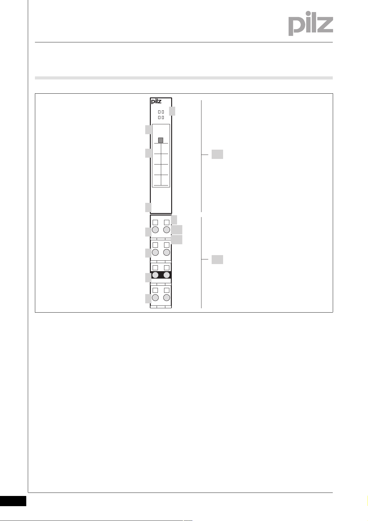
2.2 Front view
2.2Front view2200Front view2-BA_Fron tansicht
2-2
][BA_Frontansicht Legende Diag/Stat
Key:
A: Electronic module
PSSu E S 4AI U
PSSu E S 4AI U-T
B: Base module
1: LEDs for
– Module diagnostics
– Status indicator
2: Labelling strip with:
– Name of electronic module
– Order number
– Serial number
Pilz GmbH & Co. KG, Felix-Wankel-Straße 2, 73760 Ostfildern, Germany
Telephone: +49 711 3409-0, Telefax: +49 711 3409-133, E-Mail: pilz.gmbh@pilz.de
– Hardware version number
–2D code
3: Labelling strip for the terminal configuration on the base module
4: Name of electronic module
5: Connection level 1
6: Connection level 2
Page 11

2 Overview
2.2 Front view
7: Connection level 3
8: Connection level 4
9: Square mounting holes (connection levels 1, 2, 3 and 4)
– With screw to loosen/tighten the screw terminal on base modules
with screw terminals
– With mechanism to operate the cage clamp on base modules with
cage clamp terminals
10: Round connection holes (connection levels 1, 2, 3 and 4) for con-
necting the signal lines
11: Mounting slot for colour marker to label the connection level (con-
nection levels 1, 2, 3 and 4)
Pilz GmbH & Co. KG, Felix-Wankel-Straße 2, 73760 Ostfildern, Germany
Telephone: +49 711 3409-0, Telefax: +49 711 3409-133, E-Mail: pilz.gmbh@pilz.de
2-3
Page 12

2 Overview
2-4
Pilz GmbH & Co. KG, Felix-Wankel-Straße 2, 73760 Ostfildern, Germany
Telephone: +49 711 3409-0, Telefax: +49 711 3409-133, E-Mail: pilz.gmbh@pilz.de
Page 13

3 Safety
3.1 Intended use
33000SafetySafety3-3.1Intended use3100Intended use3-][Gerätebe schreibung ST-Mo dule Sys A + B
][Gertebeschreibung ST-AI
Bestimm_Verwend_ Zusatz-(T)
Bestimmung/Gertebeschreibung_Ausschluss
The module may be used for standard applications in system environment A and B.
The module provides analogue inputs. It may be used as an input module for standard functions.
The module PSSu E S 4AI U-T is suitable for use where there are increased environmental requirements (see Technical Details).
Intended use includes making the electrical installation EMC-compliant.
Please refer to the guidelines stated in the "PSSuniversal Installation
Manual". The module is designed for use in an industrial environment. It
is not suitable for use in a domestic environment, as this can lead to interference.
Bestimm_Verwend_Info_PSSu_ab_1.4.0_PAS4000_ab_1.1.1
Bestimm_Basismodule Ser
Bestimm_Basismodule Ser-T
The following is deemed improper use in particular:
Any component, technical or electrical modification to the module
Use of the module outside the areas described in this manual
Use of the module outside the technical details (see chapter entitled
"Technical Details")
INFORMATION
The module is supported by
PSSuniversal Configurator and PSSuniversal Assistant from
Version 1.4.0
PAS4000 from Version 1.1.1
– We recommend that you always use the latest version
(download from www.pilz.de).
The PSSu E S 4AI U module may be used in conjunction with the follow-
ing base modules:
PSSu BP 1/8S
PSSu BP 1/8C
PSSu BP 1/12S
PSSu BP 1/12C
PSSu BP-C 1/8S
PSSu BP-C 1/8C
PSSu BP-C 1/12S
PSSu BP-C 1/12C
Pilz GmbH & Co. KG, Felix-Wankel-Straße 2, 73760 Ostfildern, Germany
Telephone: +49 711 3409-0, Telefax: +49 711 3409-133, E-Mail: pilz.gmbh@pilz.de
3-1
Page 14

3 Safety
3.1 Intended use
The PSSu E S 4AI U-T module may be used in conjunction with the following base modules:
PSSu BP 1/8S-T
PSSu BP 1/8C-T
PSSu BP 1/12S-T
PSSu BP 1/12C-T
PSSu BP-C 1/8S-T
PSSu BP-C 1/8C-T
PSSu BP-C 1/12S-T
PSSu BP-C 1/12C-T
3-2
Pilz GmbH & Co. KG, Felix-Wankel-Straße 2, 73760 Ostfildern, Germany
Telephone: +49 711 3409-0, Telefax: +49 711 3409-133, E-Mail: pilz.gmbh@pilz.de
Page 15

3 Safety
3.2 Safety regulations
3.2Safety regulations3200Safety regulation s3-
3.2.1 Use of qualified personnel
Use of qualified personnel3-Sich Qualif. Personal
The products may only be assembled, installed, programmed, commissioned, operated, maintained and decommissioned by competent persons.
A competent person is someone who, because of their training, experience and current professional activity, has the specialist knowledge required to test, assess and operate the work equipment, devices,
systems, plant and machinery in accordance with the general standards
and guidelines for safety technology.
It is the company's responsibility only to employ personnel who:
Are familiar with the basic regulations concerning health and safety /
accident prevention
Have read and understood the safety guidelines given in this descrip-
tion
Have a good knowledge of the generic and specialist standards ap-
plicable to the specific application.
3.2.2 Warranty and liability
Warranty and liability3-Sich Gewhrleistung
3.2.3 Disposal
Disposal3-Si ch Entsorgung
All claims to warranty and liability will be rendered invalid if:
The product was used contrary to the purpose for which it is intended
Damage can be attributed to not having followed the guidelines in the
manual
Operating personnel are not suitably qualified
Any type of modification has been made (e.g. exchanging compo-
nents on the PCB boards, soldering work etc.).
In safety-related applications, please comply with the mission time t
M
in the safety-related characteristic data.
When decommissioning, please comply with local regulations regard-
ing the disposal of electronic devices (e.g. Electrical and Electronic
Equipment Act).
Pilz GmbH & Co. KG, Felix-Wankel-Straße 2, 73760 Ostfildern, Germany
Telephone: +49 711 3409-0, Telefax: +49 711 3409-133, E-Mail: pilz.gmbh@pilz.de
3-3
Page 16

3 Safety
3-4
Pilz GmbH & Co. KG, Felix-Wankel-Straße 2, 73760 Ostfildern, Germany
Telephone: +49 711 3409-0, Telefax: +49 711 3409-133, E-Mail: pilz.gmbh@pilz.de
Page 17

4 Function description
IN ADC
Limit
values
Data
format
ST
module
bus
Manufact.
scaling
User
scaling
4.1 Module features
44000Function descriptionFunction description4-4.1Module features4100Module features4-
4.1.1 Functions
Functions4-][Funktionsbeschreibung BA Einlei tung ST-AI
The module supply provides the module with voltage.
The input signals are read in, analogue prefiltered and converted into
digital signals. The resolution is 12 bits (4095 steps) and is converted
into a 16 Bit value. Additional signal processing can be defined using the
system software (see schematic representation of signal processing).
The individual steps are described in the "Configuration" section.
The input signals are transmitted to the head module via the ST module
bus. As an option the input module can send status information for each
input.
All the configuration data is stored in the head module and is assigned
to the input module on restart. This way the configuration data is retained even if you change the input module.
][Funktionsdiagramm ST-AI ohne Filter
Schematic representation of signal processing:
4.1.2 Integrated protection mechanisms
Integrated protection mechanisms4-][Schutzmechanismen E/A-Module
When the PSSu E F PS1(-T) is used to supply the system, the module
supply is buffered for 20 ms if the supply voltage is interrupted.
][Schutzmechanismen ST-Module
Pilz GmbH & Co. KG, Felix-Wankel-Straße 2, 73760 Ostfildern, Germany
Telephone: +49 711 3409-0, Telefax: +49 711 3409-133, E-Mail: pilz.gmbh@pilz.de
The module detects the following errors:
Start-up error
Configuration error
ST communication error
Bus termination error
4-1
Page 18

4 Function description
4.2 Configuration
4.2Configuration4200Configuration4-][Funktionsbeschreibung_BA_Konfig Einführung
The module can be configured using the system software.
4-2
Pilz GmbH & Co. KG, Felix-Wankel-Straße 2, 73760 Ostfildern, Germany
Telephone: +49 711 3409-0, Telefax: +49 711 3409-133, E-Mail: pilz.gmbh@pilz.de
Page 19

4 Function description
ADC
raw value
Raw value
output?
Manuf.
scaling
active?
Hardware
calibration
Manufacturer
scaling
User
scaling
active?
User
scaling
Output
formats
N
Y
Y
YN
N
4.2 Configuration
4.2.1 Scaling
Scaling4-][Funktionsbeschreibung _BA_Konfig Skalier Ein bersicht
Scaling is a multi-stage process to adapt the values from the AD converter. The straight path in the diagram indicates the default configuration.
Pilz GmbH & Co. KG, Felix-Wankel-Straße 2, 73760 Ostfildern, Germany
Telephone: +49 711 3409-0, Telefax: +49 711 3409-133, E-Mail: pilz.gmbh@pilz.de
4-3
Page 20

4 Function description
4.2 Configuration
4.2.1.1 ADC raw value and initialisation value
ADC raw value and initialis ation value4-][Funktionsbeschreibung_BA_Konfig Skalier ADC
You can configure each channel so that the raw value from the AD converter is issued directly, without calibration or scaling.
If the AD converter fails to supply a valid value, the module will adopt the
ADC initialisation value for this channel instead. The default value is
(1000H).
4096
D
4.2.1.2 Hardware calibration
Hardware calibration4-][Funktionsbeschreibung_BA_Konfig Skalier HW-Abgleich
Each channel is calibrated ex-works in order to correct component dispersion and other influences.
4.2.1.3 Manufacturer scaling
Manufacturer scaling4-][Funktionsbeschreibung_BA_Konfig Skalier Herst. Ein
The range is divided so that zero is assigned the value 0 and the end
point is assigned the value 4095
(0FFFH).
D
The manufacturer scaling is used to define the offset (zero point compensation) and gain (amplification) of the digital signal.
Manufacturer scaling active (default setting)
Default values for manufacturer scaling:
– Offset (b
–Gain (a
): 0
1
): 8194D (2002H)
1
INFORMATION
The default setting for gain (a
) means an amplification factor of
1
8.
4-4
Pilz GmbH & Co. KG, Felix-Wankel-Straße 2, 73760 Ostfildern, Germany
Telephone: +49 711 3409-0, Telefax: +49 711 3409-133, E-Mail: pilz.gmbh@pilz.de
Page 21

4 Function description
4.2 Configuration
The digital value after manufacturer scaling is calculated using the
following formula:
y = (a
y = (a
Key:
y: Digital value after manufacturer scaling
x: Digital value before manufacturer scaling
a
b
a
/ 1024D * x) + b1 or
1
/ 400H * x) + b
1
: Gain
1
: Offset
1
/ 1024D: Amplification factor
1
INFORMATION
With the given amplification factor, gain (a
lows:
Gain (a
Amplification by 5 % is therefore:
1.05 * 1024
1
) = Amplification factor * 1024
1
= 1075
D
D
) is calculated as fol-
1
D
Arithmetic examples using decimal values:
Digital value
before manufacturer
scaling (x)
1 000 1 024 0 1 1 000
1 000 2 048 0 2 2 000
1 000 8 192 0 8 8 000
1 000 1 075 500 1,05 1 550
1 000 512 -50 0,5 450
Gain (a1) Offset (b1) Amplification factor
/ 1024D)
(a
1
Value after
manufacturer scaling (y)
The module always uses two's complement representation for internal
processing, irrespective of the configured data format. The values from
to FFFFH form a number circle in the two's complement repre-
0000
H
sentation. 8000
lowest negative number (= -32 768
value never falls below -32,768
][Funktionsbeschreibung_BA_Konfig Skalier ST 4xU
follows 7FFFH (= 32 767D) and is interpreted as the
H
). 32 767D is never exceeded; the
D
.
D
Pilz GmbH & Co. KG, Felix-Wankel-Straße 2, 73760 Ostfildern, Germany
Telephone: +49 711 3409-0, Telefax: +49 711 3409-133, E-Mail: pilz.gmbh@pilz.de
4-5
Page 22

4 Function description
5 V 6 V 7 V 8 V 9 V4 V3 V2 V1 V0 V 10 V
32 76729 49026 21422 93719 66016 38413 1079 8306 5533 2770
4.2 Configuration
Analogue value and typical digital value with a voltage range of
0 ... +10 V plus default values:
Analogue value of voltage Hexadecimal digital value Decimal digital value
0V 0 0
5 V 4000 16 384
10 V 7FFF 32 767
4.2.1.4 User scaling
User scaling4-][Funktionsbeschreibung_BA_Konfig Skalier Anwend Ein
User scaling is a second level of scaling. You can use this scaling to correct local influences. The function is the same as that of manufacturer
scaling, but a different value is used for amplification factor 1:
y = (a
y = (a
a2 = Amplification factor * 256
/ 256D * x) + b2 or
2
/ 100H * x) + b
2
2
D
User scaling is deactivated in the default setting. The default value for
offset is 0. The default value for gain is 256
(100H). That corresponds
D
to amplification factor 1.
Key:
y: Digital value after user scaling
x: Digital value before user scaling
a
: Gain
2
b
: Offset
2
a
/ 1024D: Amplification factor
2
4-6
Pilz GmbH & Co. KG, Felix-Wankel-Straße 2, 73760 Ostfildern, Germany
Telephone: +49 711 3409-0, Telefax: +49 711 3409-133, E-Mail: pilz.gmbh@pilz.de
Page 23

4 Function description
4.2 Configuration
4.2.1.5 Example calculation
Example calculation4-][Funktionsbeschrei bung_BA_Konfig Skalier Bsp Ein-U
Task:
When there is 10 V at the input, the PII should show a decimal value of
10 000. User scaling (Gain a
scaling should not be changed. All numbers are decimals.
Solution:
Manufacturer scaling
/ 1024 * x) + b
y = (a
1
and user scaling
y = (a
/ 256 * x) + b
2
act consecutively, giving:
y = (a
/ 256 * ((a1 / 1024 * x) + b1)) + b2 or:
2
* a2 * x / 262144) + (a2 * b1 / 256) + b
y = (a
1
) should be used in this case. Manufacturer
2
1
2
2
With default values for a1 = 8194, b1 = 0 and the default value b2 = 0:
/ 32 * x
y = a
2
= y * 32 / x
a
2
Due to the hardware calibration the converter's input range is divided so
that the 10 V end point is assigned the value x = 4095. With the default
values x = 4095 and y= 10 000 the result is:
Gain a
= 78
2
Pilz GmbH & Co. KG, Felix-Wankel-Straße 2, 73760 Ostfildern, Germany
Telephone: +49 711 3409-0, Telefax: +49 711 3409-133, E-Mail: pilz.gmbh@pilz.de
4-7
Page 24

4 Function description
4.2 Configuration
4.2.2 Limit values
Limit values4-][Funktionsbeschreibung_BA_Konfig Grenzwert ST-AI allgemein
The module has range monitoring and limit value monitoring on each
channel:
Range monitoring
– Upper limit value: 4095
– Lower limit value: -4095
– The module compares the upper and lower limit value with the dig-
ital value after the hardware calibration (values with 12 bits plus
sign) and writes the result of the comparison as follows:
– System environment A:
In the status byte (see "PSSu assignment in system environment
A")
– System environment B:
In the I/O data element "Overrange" or "Underrange" (see "PSSu
assignment in system environment B").
– The limit of the measuring range corresponds to 4095
Limit value monitoring
– Limit value 1
– Limit value 2
– The module compares limit value 1 and limit value 2 with the digital
value after scaling (values with 15 bits plus sign) and writes the result of the comparison as follows:
– System environment A:
In the status byte (see "PSSu assignment in system environment
A")
– System environment B:
In the I/O data element "LimitValue1" or "LimitValue2" (see
"PSSu assignment in system environment B").
– The limit of the measuring range corresponds to 32 767
fault scaling values.
D
D
.
D
with de-
D
4-8
][Funktionsbeschreibung_BA_Konfig Grenzwert ST-Ein 4xU
You can change the default values in the system software.
Pilz GmbH & Co. KG, Felix-Wankel-Straße 2, 73760 Ostfildern, Germany
Telephone: +49 711 3409-0, Telefax: +49 711 3409-133, E-Mail: pilz.gmbh@pilz.de
Page 25

4 Function description
4.2 Configuration
Conversion of analogue limit values into decimal values (n) for the
system software:
4.2.3 Data formats
Data formats4-][Funktionsbeschrei bung_BA_Konfig Format ST-Ein 4xU
n = 32 768 * U
Limit
/ 10 V
Key:
U
: Analogue value at the input
Limit
Example:
Voltages at the input, which are to be monitored through the limit val-
ues:
– Limit value 1 is to be 8 V.
– Limit value 2 is to be 5 V.
Entry in the system software:
– Limit value 1 corresponds to 26 214
– Limit value 2 corresponds to 16 384
The way in which the analogue value is displayed depends on the voltage range, on scaling and on the data format. The following examples
show the relationship between the values with default scaling.
The module uses the following data format:
Two's complement (default)
The digital values are transferred with 15 bits plus a sign bit (MSB).
The MSB is always "0" with positive numbers.
Analogue value and typical digital value with two's complement representation:
Analogue value of voltage Decimal digital value Binary digital value Hexadecimal digital value
0 V 0 0000 0000 0000 0000 0000
5 V 16 384 0100 0000 0000 0000 4000
10 V 32 767 0111 1111 1111 1111 7FFF
H
H
H
Pilz GmbH & Co. KG, Felix-Wankel-Straße 2, 73760 Ostfildern, Germany
Telephone: +49 711 3409-0, Telefax: +49 711 3409-133, E-Mail: pilz.gmbh@pilz.de
4-9
Page 26

4 Function description
4.2 Configuration
4.2.4 Summary and overview
Summary and overview4-][Funktionsbeschreibung_BA_Zusatz Tabelle ST-Ein 4xU
The module has the following configuration options:
Default value
Input range 0 0 V … 10 V (cannot be changed)
Manufacturer scaling active 1/TRUE Activated
Manufacturer scaling offset 0 Offset: Magnitude 0
Manufacturer scaling gain 8194
User scaling active 0/FALSE deactivated
User scaling offset 0 Offset: Magnitude 0
User scaling gain 256
Range monitoring active 1/TRUE Activated
Upper limit value 4095
Lower limit value -4095
Limit value 1 active 0/FALSE deactivated
Limit value 1 -32 767 Lower limit of number range
Limit value 2 active 0/FALSE deactivated
Limit value 2 32 767
Sign and magnitude representation
active
Output ADC raw value only 0/FALSE deactivated
ADC initialisation value 4096
D
D
D
D
D
0/FALSE Deactivated; two's complement is activated
D
Key
8x amplification, displaced three bit places
1x amplification, signal unchanged
Upper limit of number range
Lower limit of number range
Upper limit of number range
4096 D (1000H) is issued when no data is detected.
4-10
Pilz GmbH & Co. KG, Felix-Wankel-Straße 2, 73760 Ostfildern, Germany
Telephone: +49 711 3409-0, Telefax: +49 711 3409-133, E-Mail: pilz.gmbh@pilz.de
Page 27

4 Function description
4.2 Configuration
4.2.5 PSSu assignment in system environment A
PSSu assignment in syst em environment A4-
4.2.5.1 Addresses in the process image
Addresses in the process image4-][Funktionsbeschreibung_BA_PA 4 x ST-Ein
Each input occupies 16 consecutive bit addresses for the input data.
Each input occupies an additional 8 consecutive bit addresses for the
status byte, where this has been configured for the input. If the status
byte is configured to be transferred without input data, each input occupies 8 consecutive bit addresses. All the status bytes are displayed first
in the PII, followed by the input data.
Configuration Standard bus system
ST-PII ST-PIO
Send input data 64 Bit - - Send status byte ("R") 32 Bit - - -
Bit sequence in the PII, without status byte:
Input PII Assignment
Input I0 1 LSB input data
... ...
16 MSB input data
Input I1 17 LSB input data
... ...
32 MSB input data
Input I2 33 LSB input data
... ...
48 MSB input data
Input I3 49 LSB input data
... ...
64 MSB input data
Pilz GmbH & Co. KG, Felix-Wankel-Straße 2, 73760 Ostfildern, Germany
Telephone: +49 711 3409-0, Telefax: +49 711 3409-133, E-Mail: pilz.gmbh@pilz.de
4-11
Page 28

4 Function description
4.2 Configuration
Bit sequence in the PII, with status byte:
Input PII Assignment
Input I0 1 LSB status byte
... ...
8MSB status byte
Input I1 9 LSB status byte
... ...
16 MSB status byte
Input I2 17 LSB status byte
... ...
24 MSB status byte
Input I3 25 LSB status byte
... ...
32 MSB status byte
Input I0 33 LSB input data
... ...
48 MSB input data
Input I1 49 LSB input data
... ...
64 MSB input data
Input I2 65 LSB input data
... ...
80 MSB input data
Input I3 81 LSB input data
... ...
96 MSB input data
4-12
Pilz GmbH & Co. KG, Felix-Wankel-Straße 2, 73760 Ostfildern, Germany
Telephone: +49 711 3409-0, Telefax: +49 711 3409-133, E-Mail: pilz.gmbh@pilz.de
Page 29

4 Function description
4.2 Configuration
Bit sequence in the PII, status byte only (no input data):
Input PII Assignment
Input I0 1 LSB status byte
... ...
8MSB status byte
Input I1 9 LSB status byte
... ...
16 MSB status byte
Input I2 17 LSB status byte
... ...
24 MSB status byte
Input I3 25 LSB status byte
... ...
32 MSB status byte
Pilz GmbH & Co. KG, Felix-Wankel-Straße 2, 73760 Ostfildern, Germany
Telephone: +49 711 3409-0, Telefax: +49 711 3409-133, E-Mail: pilz.gmbh@pilz.de
4-13
Page 30

4 Function description
4.2 Configuration
4.2.5.2 Status byte
Status byte4-][BA_Be trieb ST-Ein Statusbyte
ST modules for analogue input can transfer a variety of status informa-
tion to the ST-PII (see table below for the conveyed status). The informa-
tion is transmitted using the input's status byte. Read access (R) is
configured for the input for that purpose.
Structure and contents of the status byte:
Bit number Contents Key
0 0 Input value above the lower limit value
1 Value below the lower limit value:
1 0 Input value below the upper limit value
1 Value above the upper limit value
2 / 3 0 0 Limit value 1 inactive
0 1 Input value greater than or equal to limit value 1
1 0 Input value less than limit value 1
1 1 Reserved
4 / 5 0 0 Limit value 2 inactive
0 1 Input value greater than limit value 2
1 0 Input value less than or equal to limit value 2
1 1 Reserved
6 0 Valid data from A/D converter
1 No valid data from A/D converter
70Reserved
1 Reserved
4-14
Pilz GmbH & Co. KG, Felix-Wankel-Straße 2, 73760 Ostfildern, Germany
Telephone: +49 711 3409-0, Telefax: +49 711 3409-133, E-Mail: pilz.gmbh@pilz.de
Page 31

4 Function description
4.2 Configuration
4.2.6 PSSu assignment in system environment B
PSSu assignment in syst em environment B4-][Funktionsbeschreibung_Zusatz I/O-Daten Sys B
][Funktionsbeschreibung PSSu E S 4AI U
Data access is via pre-defined I/O data types:
I/O data name I/O data type I/O data element Meaning
I0(11)
I1(21)
I2(14)
I3(24)
ST_I_AI Data: WORD Input data I0 ... I3
Underrange: BOOL 0: Input value above the lower
limit value
1: Value below the lower limit
value
Overrange: BOOL 0: Input value below the upper
limit value
1: Value above the upper limit
value
LimitValue1: BOOL 0: Limit value 1 inactive
1: Input value greater than or
equal to limit value 1
LimitValue2: BOOL 0: Limit value 2 inactive
1: Input value greater than or
equal to limit value 2
Pilz GmbH & Co. KG, Felix-Wankel-Straße 2, 73760 Ostfildern, Germany
Telephone: +49 711 3409-0, Telefax: +49 711 3409-133, E-Mail: pilz.gmbh@pilz.de
4-15
Page 32

4 Function description
4-16
Pilz GmbH & Co. KG, Felix-Wankel-Straße 2, 73760 Ostfildern, Germany
Telephone: +49 711 3409-0, Telefax: +49 711 3409-133, E-Mail: pilz.gmbh@pilz.de
Page 33

5 Installation
12,6 mm
76 mm
52,1 mm8,1 mm
67,7 mm
12,6 mm
56,1 mm 71,8 mm
0,8 mm
128,9 mm
72,6 mm
(2.051")(0.319")
(0.496")
(2.858")
(0.496")
(2.99")
(2.209") (2.827")
(0.031")
(5.075")
(2.665")
5.1 General installation guidelines
55000InstallationInstallation5-5.1General installation guidelines5100General installation guidelines5-][Montage BA E-Modul Allgemein
Montage_EMV ESD
5.1.1 Dimensions
Dimensions5-][Abmessungen 1xR + 1xRL
Please also refer to the PSSuniversal Installation Manual.
CAUTION!
Damage due to electrostatic discharge!
Electrostatic discharge can damage components. Ensure
against discharge before touching the product, e.g. by touching
an earthed, conductive surface or by wearing an earthed armband.
Base modules with four connection levels:
Pilz GmbH & Co. KG, Felix-Wankel-Straße 2, 73760 Ostfildern, Germany
Telephone: +49 711 3409-0, Telefax: +49 711 3409-133, E-Mail: pilz.gmbh@pilz.de
5-1
Page 34

5 Installation
12,6 mm
76 mm
52,1 mm8,1 mm
67,7 mm
82,0 mm 71,8 mm
0,8 mm
72,6 mm
(2.051")(0.319")
(2.858")
(0.496")
(2.99")
(3.228") (2.827")
(0.031")
(2.665")
12,6 mm
(0.496")
154,6 mm
(6.087")
5.1 General installation guidelines
Base modules with six connection levels:
5-2
Pilz GmbH & Co. KG, Felix-Wankel-Straße 2, 73760 Ostfildern, Germany
Telephone: +49 711 3409-0, Telefax: +49 711 3409-133, E-Mail: pilz.gmbh@pilz.de
Page 35

5 Installation
[2]
[1]
[3]
5.2 Installing the base module
5.2Installing the base module5200Installing the base module5-][Montage Basismodul
Prerequisite:
The head module must be installed.
If the head module does not have an integrated power supply, a sup-
ply voltage module must be installed to the right of the head module.
Please note:
For mechanical reasons it is not possible to mix base modules with
screw terminals and base modules with cage clamp terminals.
All contacts should be protected from contamination.
The mechanics of the base modules are designed for 50 plug in/out
cycles.
Procedure:
We recommend that you wire up the base modules before inserting
the electronic modules.
Slot the groove on the base module on to the mounting rail from be-
low [1].
Push the base module back [2] until you hear it lock into position.
On the mounting rail, slide the base module to the left until you hear
the two lateral mounting hooks on the adjacent module lock into position [3].
Schematic representation:
Pilz GmbH & Co. KG, Felix-Wankel-Straße 2, 73760 Ostfildern, Germany
Telephone: +49 711 3409-0, Telefax: +49 711 3409-133, E-Mail: pilz.gmbh@pilz.de
5-3
Page 36

5 Installation
[2]
[1]
[1]
5.3 Inserting and removing an electronic module
5.3Inserting and removing an electronic module5300Inserting and removing an electronic module5-
5.3.1 Inserting an electronic module
Inserting an electronic module5-][Elektronikmodul stecken
Procedure:
The electronic module must audibly lock into position [1].
Mark the electronic module using the labelling strips [2].
Schematic representation:
5-4
Pilz GmbH & Co. KG, Felix-Wankel-Straße 2, 73760 Ostfildern, Germany
Telephone: +49 711 3409-0, Telefax: +49 711 3409-133, E-Mail: pilz.gmbh@pilz.de
Page 37

5 Installation
[1]
[2]
[1]
5.3 Inserting and removing an electronic module
5.3.2 Removing an electronic module
Removing an electronic module5-][Elektronikmodul ziehen
Procedure:
Press the locking mechanisms [1] together simultaneously.
Pull out the electronic module [2].
Schematic representation:
][Elektronikmodul stecken und ziehen
Please note:
Only insert on to base modules that are already installed.
Preferably these base modules should be ready wired.
Electronic modules with outputs may only be inserted and removed
when the load is switched off. Unforeseeable error reactions may be
triggered if modules are inserted and removed under load.
When an electronic module is plugged into a base module for the first
time, one part of the coding element remains on the electronic module, while its counterpart is fixed on to the base module. This is how
the base module is coded.
The mechanics of the electronic modules are designed for 50 plug in/
out cycles.
Pilz GmbH & Co. KG, Felix-Wankel-Straße 2, 73760 Ostfildern, Germany
Telephone: +49 711 3409-0, Telefax: +49 711 3409-133, E-Mail: pilz.gmbh@pilz.de
5-5
Page 38

5 Installation
5.3 Inserting and removing an electronic module
5.3.3 Changing an electronic module during operation
Changing an electronic module during operation5-][Montage BA Hot Swapping ST-E/A-Modul
The electronic module can be hot swapped. The configuration data is re-
tained when a module is swapped.
Effects:
System environment A:
– An ST communication error may occur.
System environment B:
– While the module is disconnected, the substitute values for the
module's signals/values are used (Valid Bits = FALSE).
– Once the module is reconnected, it is reactivated automatically.
5-6
Pilz GmbH & Co. KG, Felix-Wankel-Straße 2, 73760 Ostfildern, Germany
Telephone: +49 711 3409-0, Telefax: +49 711 3409-133, E-Mail: pilz.gmbh@pilz.de
Page 39

6 Wiring
DIN 5264-A
6.1 General wiring guidelines
66000WiringWiring6-6.1General wiring gu idelines6100Gene ral wiring guideline s6-][Verdrahtung BA Einleitung
][Verdrahtung ST analog
Safe electrical isolation must be ensured for the voltage supply to the
sensors and actuators. Failure to do so could result in electric shock.
Please note:
We recommend that you use shielded signal lines.
On base modules with C-rail:
– Connect the shield to the terminals on the C-rail.
– Connect the C-rail with low impedance to the functional earth.
On base modules without C-rail:
– Connect the shield as shown in the terminal configuration section.
The module connects the shield to the mounting rail.
– Connect the mounting rail to the functional earth via an earthing
terminal.
In environments with strong EMC interference, base modules without
a C-rail provide better protection if the shield is connected.
][Verdrahtung Zusatz mit C
Use copper wiring.
The terminal configuration as stated on the front plate applies for base
modules with C-rail. The terminal configuration as stated in the technical documentation applies for all other base modules.
6.1.1 Mechanical connection of the base modules
Mechanical connection of the base modules6-][Modulverdrahtung mech
Procedure:
Use a flat blade screwdriver (DIN 5264-A)!
Strip the wire back 8 mm.
If necessary, label the connection level with a colour marker [3].
Base module with screw terminals:
– Use a screwdriver to loosen the screw on the screw terminal [1]
– Insert the stripped cable into the round fixing hole [2], as far as it
will go.
– Tighten up the screw on the screw terminal.
– Check that the cable is firmly seated.
Pilz GmbH & Co. KG, Felix-Wankel-Straße 2, 73760 Ostfildern, Germany
Telephone: +49 711 3409-0, Telefax: +49 711 3409-133, E-Mail: pilz.gmbh@pilz.de
6-1
Page 40

6 Wiring
2111
[1]
[3]
[2]
[4]
[5]
[6]
6.1 General wiring guidelines
Base module with cage clamp terminals:
– Insert the screwdriver [4] into the square hole [1].
– Insert the stripped cable into the round fixing hole [2], as far as it
will go [5].
– Pull out the screwdriver [6].
– Check that the cable is firmly seated.
][Modulverdrahtung el Sys A + B
Please note:
The minimum cable cross section for field connection terminals on the
2
base modules is 0.14 mm
The maximum cable cross section for field connection terminals is:
– Digital inputs: 1.5 mm
– Digital outputs: 2.0 mm
– Inputs/outputs on the counter modules: 1.5 mm
– Analogue inputs/outputs: 1.5 mm
– Communication cables: 1.5 mm
– Test pulse outputs: 1.5 mm
– Power supply: 2.5 mm
– Functional earth: 2.5 mm
(AWG26)
2
(AWG16)
2
(AWG14)
2
(AWG16)
2
(AWG12)
2
(AWG12)
2
(AWG16)
2
(AWG16)
2
(AWG16)
6-2
Pilz GmbH & Co. KG, Felix-Wankel-Straße 2, 73760 Ostfildern, Germany
Telephone: +49 711 3409-0, Telefax: +49 711 3409-133, E-Mail: pilz.gmbh@pilz.de
Page 41

6 Wiring
6.1 General wiring guidelines
On base modules with screw terminals:
– If you use a multi-strand cable to connect the I/Os, it is recom-
mended that you use ferrules conforming to Parts 1 and 2 of DIN
46228, 0.14 ... 1.5 mm
To crimp the ferrules you can use crimp pliers (crimp form A or C)
conforming to EN 60947-1, such as the PZ 1.5 or PZ 6.5 from
Weidmüller, for example.
– Maximum torque setting: 0.8 Nm
Use copper wiring.
2
, Form A or C, although this is not essential.
Pilz GmbH & Co. KG, Felix-Wankel-Straße 2, 73760 Ostfildern, Germany
Telephone: +49 711 3409-0, Telefax: +49 711 3409-133, E-Mail: pilz.gmbh@pilz.de
6-3
Page 42

6 Wiring
2111
2212
2313
2414
2111
2212
2313
2414
2616
2515
6.2 Terminal configuration
6.2Terminal configuration6200Terminal configuration6-][Klemmenbelegung ST-AI 4xU
Base module Terminal configuration
Screw terminals:
PSSu BP 1/8S
PSSu BP 1/8S-T
Without C-rail:
11: Input I0
Cage clamp terminals:
PSSu BP 1/8C
PSSu BP 1/8C-T
Screw terminals:
PSSu BP 1/12S
PSSu BP 1/12S-T
Cage clamp terminals:
PSSu BP 1/12C
PSSu BP 1/12C-T
21: Input I1
12-22: 0 V analogue
(12-22 linked within the base module)
13-23: Cable shield
(13-23 linked within the base module)
14: Input I2
24: Input I3
Without C-rail:
11: Input I0
21: Input I1
12-22: 0 V analogue
(12-22-15-25 linked within the base
module)
13-23: Cable shield
(13-23-16-26 linked within the base
module)
14: Input I2
24: Input I3
15-25: 0 V analogue
(12-22-15-25 linked within the base
module)
16-26: Cable shield
(13-23-16-26 linked within the base
module)
6-4
Pilz GmbH & Co. KG, Felix-Wankel-Straße 2, 73760 Ostfildern, Germany
Telephone: +49 711 3409-0, Telefax: +49 711 3409-133, E-Mail: pilz.gmbh@pilz.de
Page 43

6 Wiring
2111
2212
2313
2414
2111
2212
2313
2414
2616
2515
6.2 Terminal configuration
Base module Terminal configuration
Screw terminals:
PSSu BP-C 1/8S
PSSu BP-C 1/8S-T
With C-rail:
11: Input I0
Cage clamp terminals:
PSSu BP-C 1/8C
PSSu BP-C 1/8C-T
Screw terminals:
PSSu BP-C 1/12S
PSSu BP-C 1/12S-T
Cage clamp terminals:
PSSu BP-C 1/12C
PSSu BP-C 1/12C-T
21: Input I1
12-22: 0 V analogue
(12-22 linked within the base module)
13-23: C-rail supply,
cable screening
(13-23 linked within the base module)
14: Input I2
24: Input I3
With C-rail:
11: Input I0
21: Input I1
12-22: 0 V analogue
(12-22-15-25 linked within the base
module)
13-23: C-rail supply,
cable screening
(13-23-16-26 linked within the base
module)
14: Input I2
24: Input I3
15-25: 0 V analogue
(12-22-15-25 linked within the base
module)
16-26: C-rail supply,
cable screening
(13-23-16-26 linked within the base
module)
Pilz GmbH & Co. KG, Felix-Wankel-Straße 2, 73760 Ostfildern, Germany
Telephone: +49 711 3409-0, Telefax: +49 711 3409-133, E-Mail: pilz.gmbh@pilz.de
6-5
Page 44

6 Wiring
2111
2212
2313
2414
0 V
I0
I2
I1
I3
0 V
2111
2212
2313
2414
0 V
I0
I2
I1
I3
0 V
2111
2212
2313
2414
2616
2515
0 V
I0
I2
I1
I3
0 V
0 V0 V
2111
2212
2313
2414
2616
2515
0 V
I0
I2
I1
I3
0 V
0 V0 V
6.3 Connecting the module
6.3Connecting the module6300Connecting the module6-][Anschl uss ST-AI 4xU
Input circuit Without C-rail With C-rail
Voltage range 0 ... +10 V
single-pole, referenced to earth
Base modules with four connection
levels
Voltage range 0 ... +10 V
single-pole, referenced to earth
Base modules with six connection levels
6-6
Pilz GmbH & Co. KG, Felix-Wankel-Straße 2, 73760 Ostfildern, Germany
Telephone: +49 711 3409-0, Telefax: +49 711 3409-133, E-Mail: pilz.gmbh@pilz.de
Page 45

7 Operation
7.1 Messages
77000OperationOperation7-7.1Messages71 00Messages7-][BA_Betrieb Störung LED "Err" Sys A + B
A module error is displayed via the "Err" LED (see section entitled "Display elements"), signalled to the head module and then entered in the
head module's
Error stack, with PSSu in system environment A
][BA_Betrieb Fehler ST-A I
Errors Explanation Remedy
Start-up error Error as the PSSu system starts up Change faulty module.
Configuration error Incorrect module type configured. The configured hardware registry does
ST communication error Error during ST communication Change faulty module.
Bus termination error There is no terminating plate or there is
Diagnostic log, with PSSu in system environment B.
The module can detect the following errors:
not match the actual hardware registry.
Install a terminating plate with inte-
a bad contact with the module bus.
grated end bracket or insert the base
modules together correctly.
Pilz GmbH & Co. KG, Felix-Wankel-Straße 2, 73760 Ostfildern, Germany
Telephone: +49 711 3409-0, Telefax: +49 711 3409-133, E-Mail: pilz.gmbh@pilz.de
7-1
Page 46

7 Operation
Err
11I021
I1
Err
7.2 Display elements
7.2Display elements7200Display elements7-Anzeige Legende 2x
Key:
LED on
LED off
7.2.1 Display elements for module diagnostics
Display elements for module diagnostics7-][BA_Anzeige LED Err
The module has an LED for displaying module errors (“Err” LED).
LED Key
Name Colour Status
Err - - - No error
red Module error
7-2
Pilz GmbH & Co. KG, Felix-Wankel-Straße 2, 73760 Ostfildern, Germany
Telephone: +49 711 3409-0, Telefax: +49 711 3409-133, E-Mail: pilz.gmbh@pilz.de
Page 47

7 Operation
11I021
I1
Err
I 0 I 1
I0 I1
Err
I 2 I 3
I2 I3
7.2 Display elements
7.2.2 Display elements for input status
Display elements for input status7-][BA_Anzeige LED 4AI
Each input is assigned an LED for displaying the input status (LEDs “I0”,
“I1”, “I2” and “I3”). The green LED lights up as soon as the module detects a signal at the input that can be digitised.
LED Key
Descrip-
tion
I0 - - - No signal
Colour Status Signal Input Termi-
nal
11
detectedI0(Input 1)
green Signal
detected
I1 - - - No signal
detectedI1(Input 2)
green Signal
detected
I2 - - - No signal
detectedI2(Input 3)
green Signal
detected
I3 - - - No signal
detectedI3(Input 4)
green Signal
detected
21
14
24
Pilz GmbH & Co. KG, Felix-Wankel-Straße 2, 73760 Ostfildern, Germany
Telephone: +49 711 3409-0, Telefax: +49 711 3409-133, E-Mail: pilz.gmbh@pilz.de
7-3
Page 48

7 Operation
7-4
Pilz GmbH & Co. KG, Felix-Wankel-Straße 2, 73760 Ostfildern, Germany
Telephone: +49 711 3409-0, Telefax: +49 711 3409-133, E-Mail: pilz.gmbh@pilz.de
Page 49

8 Technical details
8.1 Technical details
88000Technical detailsTechnical details8-8.1Technical details8100Technical details8-][Technische Daten PSSu Analoge ST-Ein
Technical details
Application range Standard
Module's device code 0301h
Number of ST input bits 64
Number of ST status bits 32
Support in system environment A
from ST firmware version for other head modules 7
from ST firmware version PSSu H S PN 1
from ST firmware version PSSu WR S IDN 4
Support in system environment B
from head module ST firmware version 1.0.0
Electrical data
Internal supply voltage (module supply)
Supply voltage range of module supply 4.8 - 5.4 V
Module's current consumption 53 mA
Module's power consumption 0.26 W
Periphery's supply voltage (periphery supply)
Voltage range 16.8 - 30.0 V
Module's current consumption with no load 10 mA
Module's power consumption with no load 0.24 W
Max. power dissipation of the module 0.50 W
Inputs
Number of analogue inputs 4
Type of analogue inputs Voltage
Input range 0 .. 10 V (single-ended)
Resolution (without sign bit) 12 Bit
Max. continuous voltage 12 V
Input resistance (voltage input) 100 kOhm
Deviations from the measuring range limit value
Linearity error 0.05 %
Output variable error at 25° C 0.2 %
Temperature coefficient 0.0200 %/K
Max. measurement error during EMC test 1.0 %
Analogue input filter RC filter
Cutoff frequency 130 Hz
Potential isolation between input and voltage for the inter-
nal module bus
Potential isolation between input and periphery supply yes
Times
Typ. processing time 1.0 ms
Environmental data
Climatic suitability EN 60068-2-14, EN 60068-2-1, EN 60068-2-2,
Ambient temperature in accordance with EN 60068-2-14 0 - 60 °C
Storage temperature in accordance with EN 60068-2-1/-2 -25 - 70 °C
Climatic suitability in accordance with EN 60068-2-30,
EN 60068-2-78
Condensation no
yes
EN 60068-2-30, EN 60068-2-78
-40 - 70 °C coated version (-T)
-40 - 70 °C coated version (-T)
93 % r. h. at 40 °C
yes coated version (-T)
Pilz GmbH & Co. KG, Felix-Wankel-Straße 2, 73760 Ostfildern, Germany
Telephone: +49 711 3409-0, Telefax: +49 711 3409-133, E-Mail: pilz.gmbh@pilz.de
8-1
Page 50

8 Technical details
8.1 Technical details
Environmental data
Max. operating height above sea level 5000 m coated version (-T)
EMC EN 61000-4-2, EN 61000-4-3, EN 61000-4-4,
EN 61000-4-5, EN 61000-4-6, EN 61000-6-2,
EN 61000-6-4
Vibration to EN 60068-2-6
Frequency 10 - 150 Hz
Max. acceleration 1g
Shock stress
EN 60068-2-27 15g
11 ms
EN 60068-2-29 10g
16 ms
Protection type in accordance with EN 60529
Mounting (e.g. cabinet) IP54
Housing IP20
Terminals IP20
Airgap creepage in accordance with EN 60664-1
Overvoltage category II
Pollution degree 2
Mechanical data
Housing material
Front PC
Bottom PC
Coding PA
Dimensions
Height 76.0 mm
Width 12.6 mm
Depth 60.2 mm
Weight 37 g
Mechanical coding
Type D
Colour dark grey
Technische Daten_Satz No rmen
8-2
The standards current on 2005-04 apply.
Pilz GmbH & Co. KG, Felix-Wankel-Straße 2, 73760 Ostfildern, Germany
Telephone: +49 711 3409-0, Telefax: +49 711 3409-133, E-Mail: pilz.gmbh@pilz.de
Page 51

8 Technical details
8.2 Order reference
8.2Order reference8200Order reference8-Bestel ldaten
Order reference
Description Order no.
PSSu E S 4AI U
(Electronic module)
PSSu E S 4AI U-T
(Electronic module, coated version)
][Bestelldaten Basismodule Analog mit -T
Base modules Order no.
PSSu BP 1/8S
(Base module without C-rail with screw terminals)
PSSu BP 1/8S-T
(Base module without C-rail with screw terminals, coated
version)
PSSu BP 1/8C
(Base module without C-rail with cage clamp terminals)
PSSu BP 1/8C-T
(Base module without C-rail with cage clamp terminals,
coated version)
PSSu BP-C 1/8S
(Base module with C-rail with screw terminals)
PSSu BP-C 1/8S-T
(Base module with C-rail with screw terminals, coated version)
PSSu BP-C 1/8C
(Base module with C-rail with cage clamp terminals)
PSSu BP-C 1/8C-T
(Base module with C-rail with cage clamp terminals, coated version)
PSSu BP 1/12S
(Base module without C-rail with screw terminals)
PSSu BP 1/12S-T
(Base module without C-rail with screw terminals, coated
version)
PSSu BP 1/12C
(Base module without C-rail with cage clamp terminals)
PSSu BP 1/12C-T
(Base module without C-rail with cage clamp terminals,
coated version)
PSSu BP-C 1/12S
(Base module with C-rail with screw terminals)
PSSu BP-C 1/12S-T
(Base module with C-rail with screw terminals, coated version)
PSSu BP-C 1/12C
(Base module with C-rail with cage clamp terminals)
PSSu BP-C 1/12C-T
(Base module with C-rail with cage clamp terminals, coated version)
312 445
314 445
312 600
314 600
312 601
314 601
312 610
314 610
312 611
314 611
312 618
314 618
312 619
314 619
312 620
314 620
312 621
314 621
Pilz GmbH & Co. KG, Felix-Wankel-Straße 2, 73760 Ostfildern, Germany
Telephone: +49 711 3409-0, Telefax: +49 711 3409-133, E-Mail: pilz.gmbh@pilz.de
8-3
Page 52

8 Technical details
8-4
Pilz GmbH & Co. KG, Felix-Wankel-Straße 2, 73760 Ostfildern, Germany
Telephone: +49 711 3409-0, Telefax: +49 711 3409-133, E-Mail: pilz.gmbh@pilz.de
Page 53

...
21411-EN-02, 2011-04 Printed in Germany
© Pilz GmbH & Co. KG, 2011
+49 711 3409-444
support@pilz.com
Pilz GmbH & Co. KG
Felix-Wankel-Straße 2
73760 Ostfildern, Germany
Telephone: +49 711 3409-0
Telefax: +49 711 3409-133
E-Mail: pilz.gmbh@pilz.de
Internet: www.pilz.com
Technical support
In many countries we are
represented by our subsidiaries
and sales partners.
Please refer to our homepage
for further details or contact our
headquarters.
InduraNET p
®
, Pilz
®
, PIT
®
, PMCprotego
®
, PMI
®
, PNOZ
®
, Primo
®
, PSEN
®
, PSS
®
, PVIS
®
, SafetyBUS p
®
, SafetyEYE
®
, SafetyNET p
®
, the spirit of safety
®
are registered and protected trademarks
of Pilz GmbH & Co. KG in some countries. We would point out that product features may vary from the details stated in this document, depending on the status at the time of publication and the scope
of the equipment. We accept no responsibility for the validity, accuracy and entirety of the text and graphics presented in this information. Please contact our Technical Support if you have any questions.
Contact address
 Loading...