

Page 1

PMCtendo AC
Motors
Operating Manual – Item No. 21 894-02
Page 2

All rights to this documentation are reserved by Pilz GmbH & Co. KG. Copies may be made
for internal purposes.
Suggestions and comments for improving this documentation will be gratefully received.
The names of products, goods and technologies used in this documentation are registered
trademarks of the respective companies. Automation Workbench
®
PNOZ
, Primo®, PSS®, SafetyBUS p® are registered trademarks of Pilz GmbH & Co. KG.
®
, Pilz®, PIT®, PMI®,
Page 3

Contents
Introduction 1-1
Validity of documentation 1-2
Overview of documentation 1-3
Definition of symbols 1-4
Overview 2-1
View of servo motor 2-1
Features 2-1
Type label 2-2
Order references 2-4
Safety 3-1
Intended use 3-1
Safety guidelines 3-1
Use of qualified personnel 3-2
EMCD 3-2
Warranty and liability 3-2
Disposal 3-2
Function Description 4-1
Structure 4-1
Servo amplifier 4-1
Motor feedback system 4-2
Operating mode 4-2
Overload protection 4-2
Holding brake 4-3
Motor shaft and bearings 4-3
Transport and Storage 5-1
Transport 5-1
Storage 5-1
1Operating Manual: PMCtendo AC
Page 4

Contents
Installation 6-1
Preparing for installation 6-1
Mounting location 6-1
Mounting position 6-1
Motor 6-2
Carrying out the installation 6-2
Wiring 7-1
General requirements 7-1
Cabling 7-1
Cable cross sections 7-1
Earthing, shielding and EMC 7-2
Pin assignment and connection 7-3
Motor feedback connections 7-3
Resolver 7-3
Hiperface encoder 7-5
Connections for supply voltage, thermal switch and holding brake 7-6
General 7-6
Terminal box on servo motors AC1 and AC2 7-6
Terminal box on servo motors AC3 and AC4 7-8
Round connector for servo motors AC1 and AC2 7-9
Round connector for servo motors AC3 and AC4 7-10
Connecting the supply voltage 7-11
Connecting the holding brake 7-12
Commissioning 8-1
General requirements 8-1
Check installation and wiring 8-2
Commissioning the drive unit 8-3
Troubleshooting guidelines 8-4
Maintenance and Repair 9-1
General guidelines for maintenance and repair 9-1
Maintenance intervals 9-2
Changing the servo motor 9-3
2 Operating Manual: PMCtendo AC
Page 5

Glossary 10-1
Appendix 11-1
Changes in the documentation 11-1
Changes in Version 21 894-01 11-1
Changes in Version 21 894-02 11-1
Technical Details 12-1
General technical details 12-1
Derating 12-3
Derating diagram: Installation height 12-3
Derating diagram: Ambient temperature 12-4
Derating diagram: Operating time 12-5
Type-specific technical details 12-6
Key to the designations used in the table header 12-6
Servo motors PMCtendo AC1 12-8
Performance data: PMCtendo AC1 12-8
Mechanical data: PMCtendo AC1 12-11
Dimensions: PMCtendo AC1 12-14
Dimensioned drawing: PMCtendo AC1 12-16
Servo motors PMCtendo AC2 12-17
Performance data: PMCtendo AC2 12-17
Mechanical data: PMCtendo AC2 12-20
Dimensions: PMCtendo AC2 12-25
Dimensioned drawing: PMCtendo AC2 12-27
Servo motors PMCtendo AC3 12-29
Performance data: PMCtendo AC3 12-29
Mechanical data: PMCtendo AC3 12-30
Dimensions: PMCtendo AC3 12-32
Dimensioned drawing: PMCtendo AC3 12-33
Servo motors PMCtendo AC4 12-34
Performance data: PMCtendo AC4 12-34
Mechanical data: PMCtendo AC4 12-35
Dimensions: PMCtendo AC4 12-36
Dimensioned drawing: PMCtendo AC4 12-37
3Operating Manual: PMCtendo AC
Page 6

Page 7

Introduction
This operating manual describes the 3-phase synchronous servo motors PMCtendo AC.
The servo motors PMCtendo AC are divided into the following series:
• PMCtendo AC1
Servo motors for universal use, for large power ratings
• PMCtendo AC2
Servo motors for universal use
• PMCtendo AC3
Servo motors with low moment of inertia, dynamic version
• PMCtendo AC4
Compact servo motors, highly dynamic version
Please also refer to the operating manual for the servo amplifier you are using.
This operating manual is intended for instruction and should be retained for future
reference.
Operating Manual: PMCtendo AC 1-1
Page 8

Introduction
Validity of documentation
This documentation is valid for
• PMCtendo AC1 from Version 1.0
• PMCtendo AC2 from Version 1.0
• PMCtendo AC3 from Version 1.0
• PMCtendo AC4 from Version 1.0
It is valid until new documentation is published. The latest documentation is always
enclosed with the unit.
Operating Manual: PMCtendo AC1-2
Page 9

Overview of documentation
1 Introduction
The introduction is designed to familiarise you with the contents, structure and
specific order of this operating manual.
2 Overview
This chapter provides information on the most important features of the
servo motors PMCtendo AC.
3 Safety
This chapter must be read as it contains important information on safety regulations
and intended use.
4 Function Description
This chapter describes the servo motors PMCtendo AC and their components.
5 Transport, Unpacking, Storage
This chapter describes the procedures required when handling the servo motors.
6 Installation
This chapter explains how to install the servo motors PMCtendo AC.
7 Wiring
This chapter contains information and requirements for the electrical installation and
the servo motor connection.
8 Commissioning
This chapter describes the different requirements and options during
commissioning.
9 Maintenance and Repair
This chapter contains information and requirements for maintaining and repairing a
servo motor.
10 Glossary
This section explains the most important specialist terms that are used.
11 Appendix
12 Technical Details
Operating Manual: PMCtendo AC 1-3
Page 10
Introduction
Definition of symbols
Information in this manual that is of particular importance can be identified as follows:
DANGER!
This warning must be heeded! It warns of a hazardous situation that poses an
immediate threat of serious injury and death and indicates preventive measures that
can be taken.
WARNING!
This warning must be heeded! It warns of a hazardous situation which could lead to
serious injury or death and indicates preventive measures that can be taken.
CAUTION!
This refers to a hazard that can lead to a less serious or minor injury plus material
damage, and also provides information on preventive measures that can be taken.
NOTICE
This describes a situation in which the unit(s) could be damaged and also provides
information on preventive measures that can be taken.
INFORMATION
This gives advice on applications and provides information on special features, as well
as highlighting areas within the text that are of particular importance.
Operating Manual: PMCtendo AC1-4
Page 11
Overview
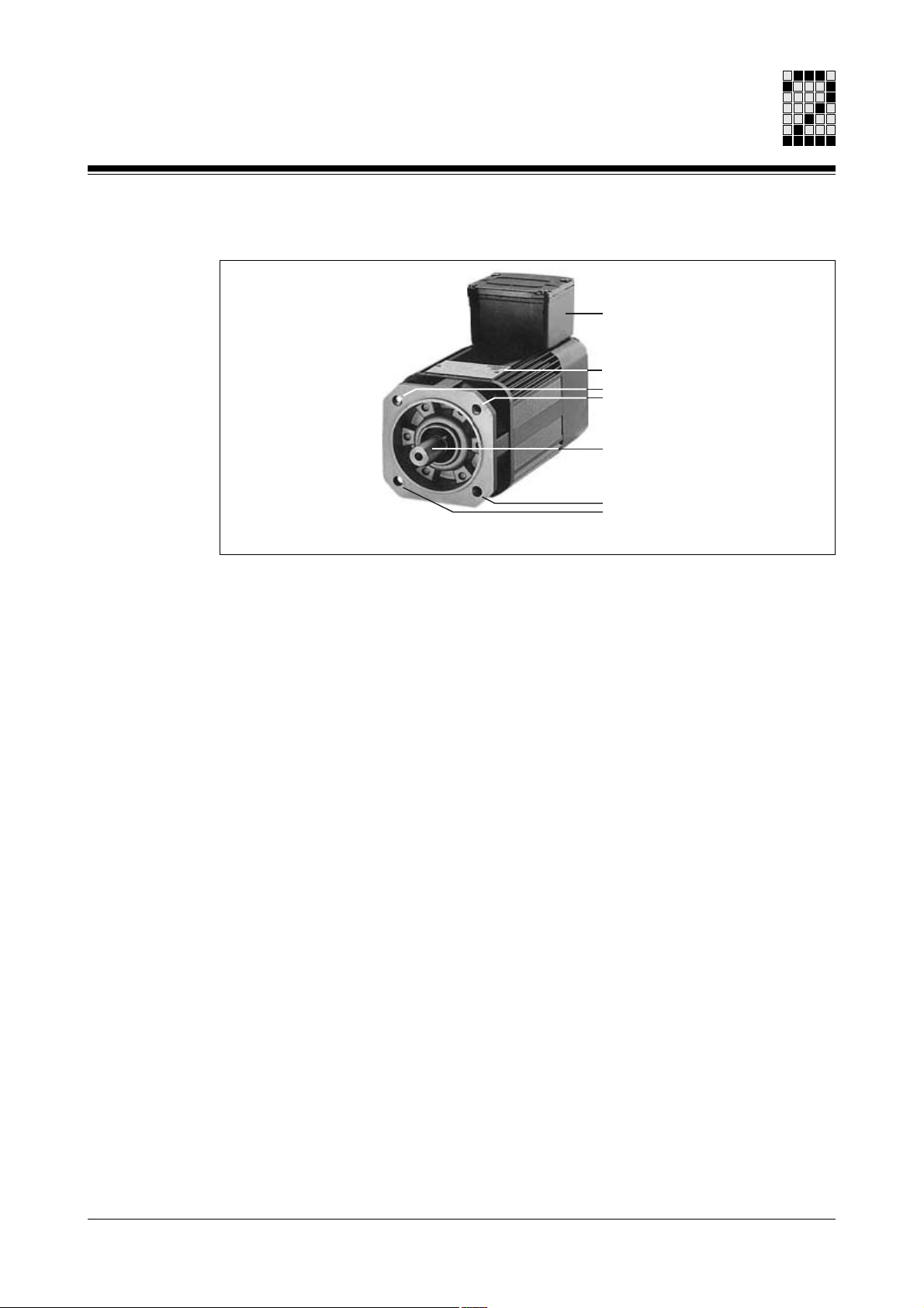
View of servo motor
Fig. 2-1: Servo motor PMCtendo AC (example)
Terminal box
(example)
Type label
Mounting holes
Motor shaft
(drive end)
Mounting holes
Features
The servo motors PMCtendo AC are particularly suitable for
• Printing and packaging machines
• Minor axes on machine tools
• Woodworking machines
• Lift drives and travelling drives
• Robotics and palletising systems
• Applications with high requirements for dynamics and controllability
The servo motors PMCtendo AC have the following features:
• 3-phase synchronous motors with permanently energised rotor (rare earth permanent
magnet)
• Sinusoidal electromotive force (EMF)
The 3 lines are connected internally in star configuration
• Motor feedback system, either
- 2-pole resolver
- Hiperface single-turn for SinCos encoder
- Hiperface multi-turn for SinCos encoder
• Drive shaft, either
- With feather key groove
- Without feather key groove, smooth shaft
• Overload protection through motor temperature monitoring
- Thermal switch (N/C contact) in the motor winding
2-1Operating Manual: PMCtendo AC
Page 12
Overview
Type label
• Holding brake (optional)
- Backlash-free permanent magnet holding brake for safe standstill of the axis when
the supply to the servo motor is switched off
• Type B5
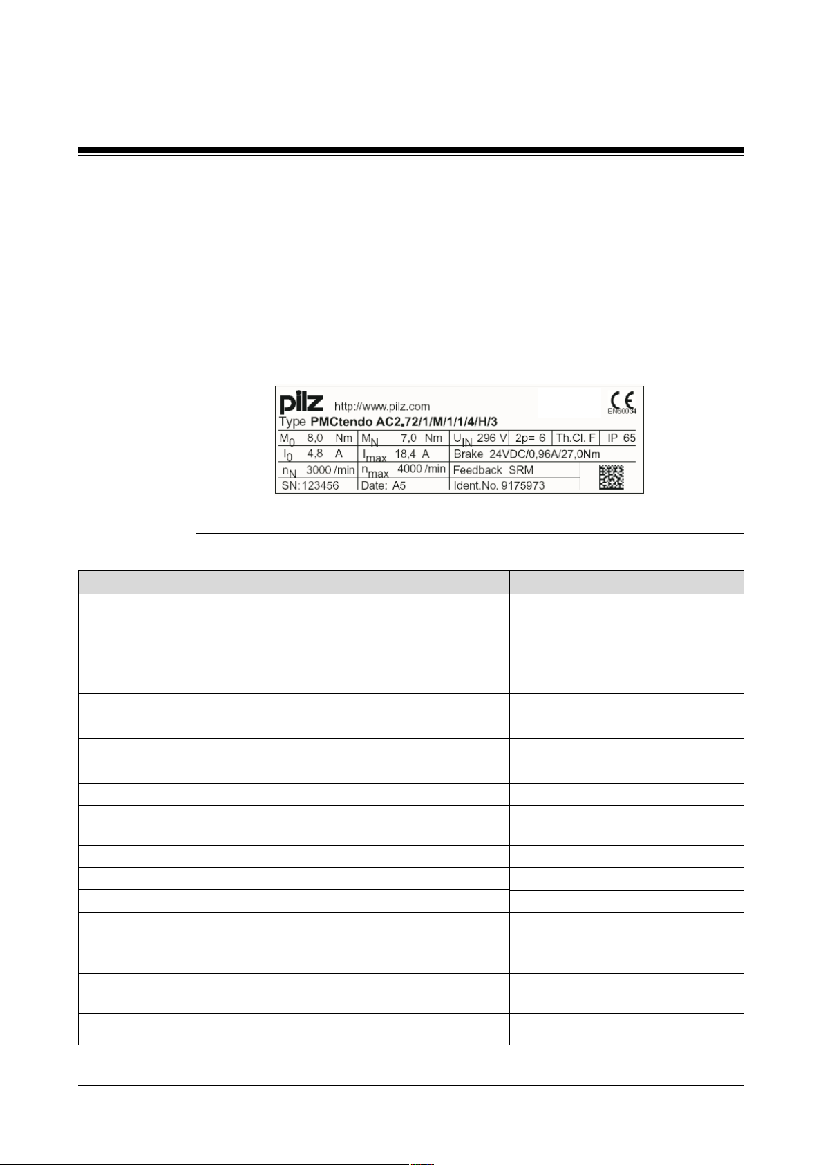
The type label contains all the key data for a servo motor.
Fig. 2-2: Type label for a servo motor PMCtendo AC (example)
Description
Type
M
0
I
0
n
N
SN
M
N
I
max
n
max
Date
U
IN
2p
Th.Cl.
IP
Brake
Feedback
Ident.No.
Key
Type of servo motor and servo motor's
order reference
(see section entitled “Order references”)
Constant standstill torque
Constant standstill current
Rated speed
Serial number
Rated torque
Peak current
Maximum speed
Code for the date of manufacture
(see table: “Code for the date of manufacture”)
Regenerated voltage
Number of motor poles
Heat class
Protection type
Data for holding brake
(see chapter entitled “Technical Details”)
Encoder type
(see table: “Encoder types”)
Material number
Information in the example
PMCtendo AC
2.72/1/M/1/1/4/H/3
8.0 Nm
4.8 A
3000/min
123456
7.0 Nm
18.4 A
4000/min
A5
296 V
6 (3 pairs of poles)
F
65
24 VDC/0.96A/27.0Nm
SRM
9175973
2-2 Operating Manual: PMCtendo AC
Page 13
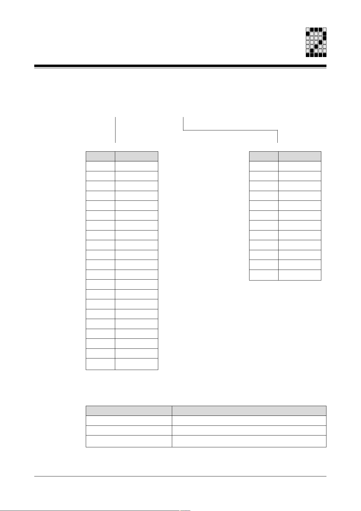
Code for the data of manufacture
The 2-digit code on the type label is structured as follows:
<Code for the year> <Code for the month>
Code
A
B
C
D
E
F
H
J
K
L
M
N
P
R
S
T
U
V
W
X
A
Year
2000
2001
2002
2003
2004
2005
2006
2007
2008
2009
2010
2011
2012
2013
2014
2015
2016
2017
2018
2019
2020
Code
1
2
3
4
5
6
7
8
9
O
N
D
Month
January
February
March
April
May
June
July
August
September
October
November
December
Encoder types
The type label distinguishes between the following encoder types:
Description
Res2
SRS
SRM
Encoder type
2-pole resolver
Encoder system for Hiperface single-turn
Encoder system for Hiperface multi-turn
2-3Operating Manual: PMCtendo AC
Page 14
Overview
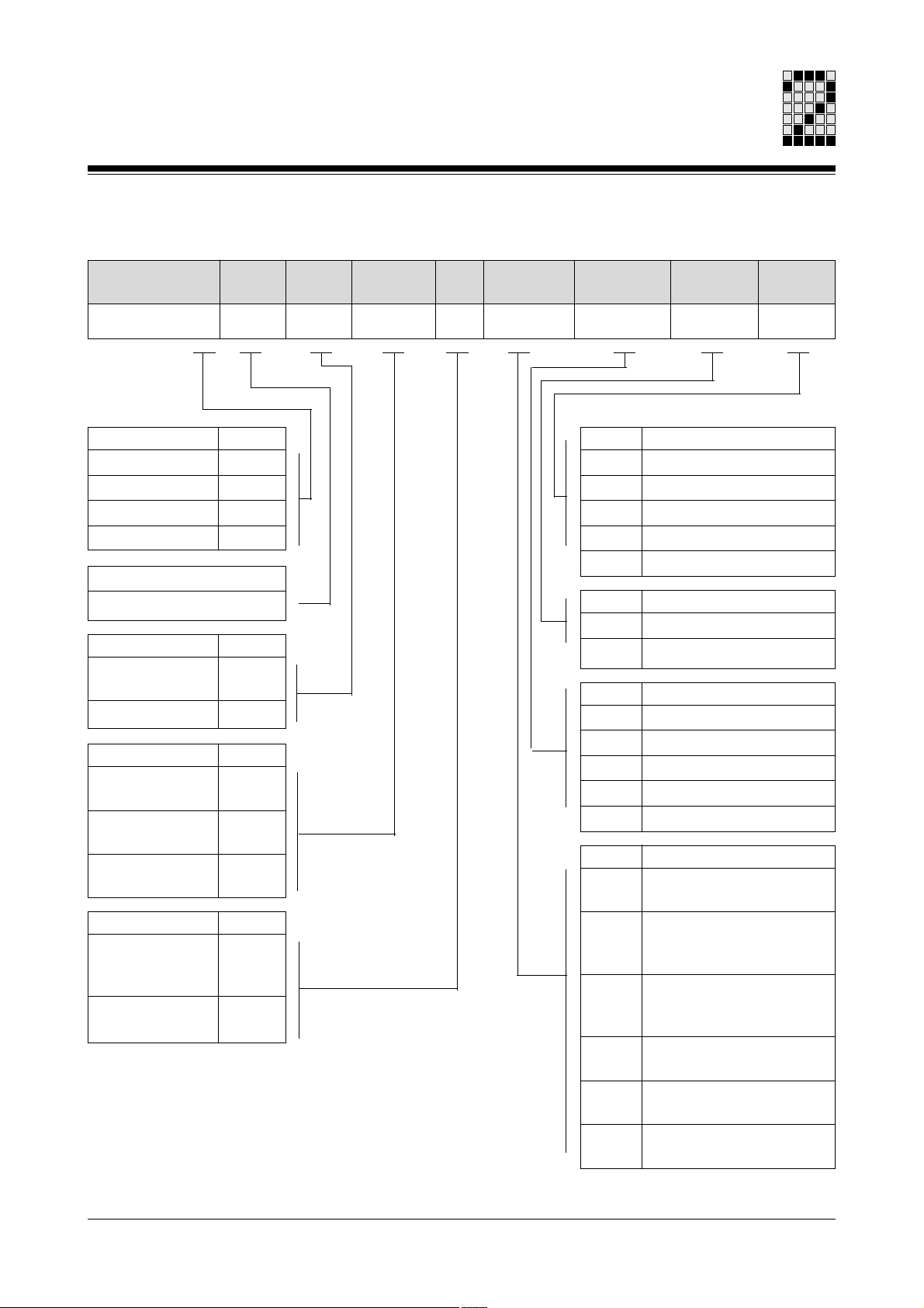
Order references
Type
Motor
size
Brake Feedback Type Con-
nection
PMCtendo AC...
Series
PMCtendo AC1
PMCtendo AC2
PMCtendo AC3
PMCtendo AC4
Code
1
2
3
4
Code for motor size
21 ... AB
Brake
Without brake
With brake
Feedback
2-pole resolver
Code
0
1
Code
5
(standard)
Hiperface
L
single-turn
Hiperface
M
multi-turn
Type
B5, shaft end with
Code
1
feather key
(standard)
B5, shaft end
2
without feather key
[1] Connection direction: see section entitled “Definition of motor ends”
Connection
direction
Code
1
2
3
4
6
Code
M
H
Code
1
2
4
5
6
Code
1
Speed
1200 min
2000 min
3000 min
4000 min
6000 min
Voltage
230 V
400 V
Connection direction [1]
To right
To left
Upwards
To B-end
To A-end
Connection
Connector for motor and
feedback on housing
2
Terminal box with cable
for motor and connector
for feedback
3
Terminal box with
connector for motor and
feedback
4
Cable for motor and
feedback
6
Angled connector for
motor and feedback
7
Angled swivel connector
for motor and feedback
Voltage Speed
-1
-1
-1
-1
-1
2-4 Operating Manual: PMCtendo AC
Page 15

Safety
Intended use
The servo motors are designed for incorporation into a machine or for assembly with
other components to form a plant or machine. They must be operated in conjunction
with servo amplifiers with speed, torque or position control.
The servo motors may not be operated directly on the mains. The servo motors must be
operated via a suitable servo amplifier which has been set with the correct parameters
(e.g. PMCtendo DD, PMCprimo Drive from Pilz).
The thermal switch incorporated into the motor winding must be monitored and
evaluated.
The following is deemed improper use:
• Any component, technical or electrical modification
• Use outside the areas described in this manual
• Use outside the documented technical details (see chapter entitled “Technical
Details”).
Safety guidelines
Failure to keep to these guidelines will render all warranty and liability claims invalid:
• All health and safety / accident prevention regulations for the particular area of
• The unit must not be put into service until it can be guaranteed that the plant or
application must be observed.
machine into which the servo motor has been incorporated meets the requirements of
the EU Directive 98/37/EC (Machinery Directive) as a whole.
3-1Operating Manual: PMCtendo AC
Page 16

Safety
Use of qualified personnel
Assembly, installation, commissioning, operation, maintenance and decommissioning
may only be undertaken by qualified personnel. Qualified personnel are people who,
because they are:
• Qualified electrical engineers
• And/or have received training from qualified electrical engineers,
are suitably experienced to operate devices, systems, plant and machinery in
accordance with the general standards and guidelines for safety technology.
EMCD
The servo motors are designed for use in an industrial environment. Interference may
occur if used in a domestic environment in conjunction with servo amplifiers.
Warranty and liability
Disposal
All claims to warranty and liability will be rendered invalid if:
• The servo motor is used contrary to the purpose for which it was intended
• Damage can be attributed to not having followed the guidelines in the manual
• Operating personnel are not suitably qualified
• Any type of modification has been made.
The servo motor must be disposed of properly when it reaches the end of its service life.
3-2 Operating Manual: PMCtendo AC
Page 17

Function Description
Structure
PMCtendo AC servo motors are 3-phase, brushless synchronous motors with
permanently energised rotor. The rotor contains rare earth permanent magnets made of
neodymium iron boron. The rare earth magnetic material is a major factor in enabling
these servo motors to be operated with high dynamics.
The 3-phase, stator winding is designed for sinusoidal commutation and enables a high
efficiency factor, while at the same time having optimum true running characteristics.
PMCtendo AC servo motors are totally enclosed, self-cooled motors and correspond to
type IC410 (in accordance with IEC 60034-6).
Servo amplifier
A suitable servo amplifier is required for commutation (e.g. PMCtendo DD, PMCprimo
Drive from Pilz). Commutation occurs electronically within the servo amplifier.
The servo motor and servo amplifier should always be regarded as one cohesive
system. The most important selection criteria are:
• Constant standstill torque M0 [Nm]
• Constant standstill current I0 [A]
• Rated speed nN [min-1]
• Mass moment of inertia of motor and load J [kgcm²]
• Effective torque (calculated) M
• Regenerative energy in braking mode
rms
[Nm]
When selecting the servo amplifier, please consider both the static and the dynamic
load (acceleration/braking).
Operating Manual: PMCtendo AC 4-1
Page 18

Function Description
Motor feedback system
PMCtendo AC servo motors may be equipped with one of the following motor feedback
systems:
• Resolver (2-pole)
The resolver determines the absolute position of the rotor to the stator within a
revolution and signals this information to the servo amplifier. This feeds sinusoidal
currents to the winding on the servo amplifier, depending on the rotor position.
• Hiperface-compatible feedback system for SinCos encoder
A Hiperface-compatible feedback system operates with differential signals in
accordance with the RS 485 specification.
The absolute position of the rotor to the stator is determined on power up and is
signalled to the counter in the servo amplifier via the parameter channel. The counter
then continues to count incrementally, based on this absolute value. For this purpose
the analogue sine/cosine voltage is transmitted via the process data channel and is
converted within the servo amplifier.
- Hiperface single-turn for SinCos encoder
With the Hiperface single-turn, only one shaft revolution is triggered. One shaft
resolution is transmitted in 32 768 steps.
- Hiperface multi-turn for SinCos encoder
With the Hiperface multi-turn, several shaft revolutions are triggered. A maximum of
4096 revolutions can be transmitted, each in 32 768 steps.
Operating mode
PMCtendo AC servo motors are designed for continuous duty. This corresponds to
operating mode S1 (in accordance with DIN EN 60 034-1).
Overload protection
PMCtendo AC servo motors have overload protection, which protects the stator winding
from damage in the case of constant overload. The motor temperature is monitored via a
thermal switch in the stator winding. The contact on the thermal switch is opened when
the winding temperature is exceeded. The switch does not protect against temporary
high overload.
The thermal switch incorporated into the motor winding must be monitored and
evaluated by the servo amplifier.
4-2 Operating Manual: PMCtendo AC
Page 19

Holding brake
As an option, the PMCtendo AC servo motors may be supplied with a built-in holding
brake, for backlash-free holding of the axis at standstill or when the supply to the plant or
machine is switched off. The permanent magnet brake blocks the rotor when the supply
voltage is switched off. Once the brake is released, the rotor can move without residual
torque.
INFORMATION
Only use the holding brake when the axes are at standstill!
It may not be used for dynamic braking mode. Make sure you read the holding brake
information provided in the chapters entitled “Wiring” and “Technical Details”.
The holding brake does not guarantee personal protection!
Personal protection can only be achieved by using a second brake and through
additional higher level design measures (e.g. guard).
Motor shaft and bearings
PMCtendo AC servo motors are available with two different types of shaft end (drive
end):
• Shaft end with feather key groove
Rotor balancing is performed using a half feather key. These shaft ends are suitable
for low loads. Under continuous duty with varying torques or strong reverse mode, the
feather key may become unseated. If this is the case the true running quality is
reduced; there is backlash. Increasing deformation can break the feather key and
damage the drive shaft.
• Smooth shaft end
With a frictional connection, torque transfer must only be achieved through surface
pressure. This guarantees a safe, backlash-free force transfer.
• Bearings
The bearings are lubricated with maintenance-free grease which is resistant to high
temperatures.
Operating Manual: PMCtendo AC 4-3
Page 20

Function Description
Notes
4-4 Operating Manual: PMCtendo AC
Page 21

Transport and Storage
Transport
The servo motors must be transported in such a way that no damage can occur.
INFORMATION
Be sure to avoid any impact, jerky movements or heavy vibration during transportation.
Storage
If a servo motor is not to be put into service immediately upon delivery, make absolutely
sure that it is stored correctly.
The servo motors should only be stored in an enclosed room that is dry, dust free and
ventilated. Please refer to the information provided under “Technical Details”.
Do not remove anti-corrosion coatings on the shaft ends, flange surfaces, etc. While in
storage, these should be inspected at defined intervals and any damage made good.
The storage site should not be liable to vibration. When servo motors are kept in storage
we recommend that the rotor is rotated at defined intervals to prevent corrosion on the
bearings.
If the servo motor has been in storage for more than 3 months, rotate the servo motor in
both directions at low speed (< 100 min-1) to ensure that the lubricant on the bearings is
distributed equally.
Operating Manual: PMCtendo AC 5-1
Page 22

Transport and Storage
Notes
5-2 Operating Manual: PMCtendo AC
Page 23
Installation
Preparing for installation
Secure the installation site in accordance with the regulations (barrier, warning signs
etc.). Installation may only be carried out by qualified personnel.
Mounting location
Please note the following when selecting the location:
• The mounting location must be free from conductive and aggressive materials.
• The unit may only be mounted on a flat, vibration-free and warp-resistant substructure.
• It is essential to comply with the ambient temperature (see chapter entitled “Technical
Details”).
Ensure there is sufficient heat dissipation; if necessary, additional ventilation should
be provided for the servo motor.
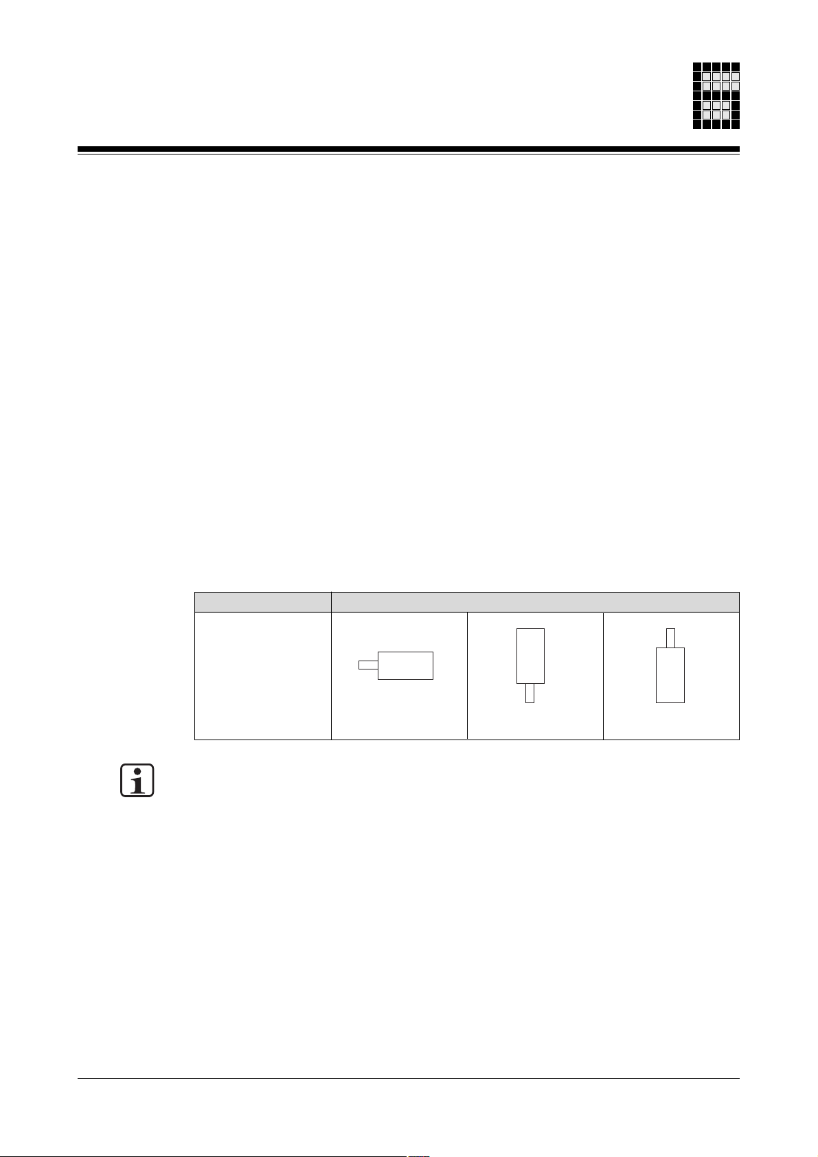
Mounting position
Permitted mounting positions:
Design
Permitted mounting positions
B5
IM B5
IM V1
IM V3
INFORMATION
• The mounting position IM V3 (DIN EN 60034-7) is not recommended in conjunction
with gear units!
• With the mounting position IM V3 (DIN EN 60034-7), ensure that liquids cannot
penetrate into the bearings, whether during installation or during operation.
Operating Manual: PMCtendo AC 6-1
Page 24
Installation
Motor
• Check the servo motor for any transport damage. Never install a servo motor that
shows clear signs of damage!
• Ensure that any anti-corrosion agents and/or contamination on the shaft end (drive
end) are thoroughly removed. This can be done using a standard solvent. Make sure
that the solvent cannot come into contact with the gaskets and/or bearings, otherwise
materials may be damaged!
Carrying out the installation
WARNING!
Electric shock
Contact with live parts will result in serious injury.
The motor should always be installed with the supply voltage switched off. Switch off
the supply voltages to all connected devices!
Hazardous values may still be present up to 5 minutes after the voltage is switched off,
due to residual charges in the servo amplifier’s capacitors.
When the shaft is rotating (externally driven, running down) the motor acts as a
generator. This means that hazardous voltages will be present at the connection
terminals.
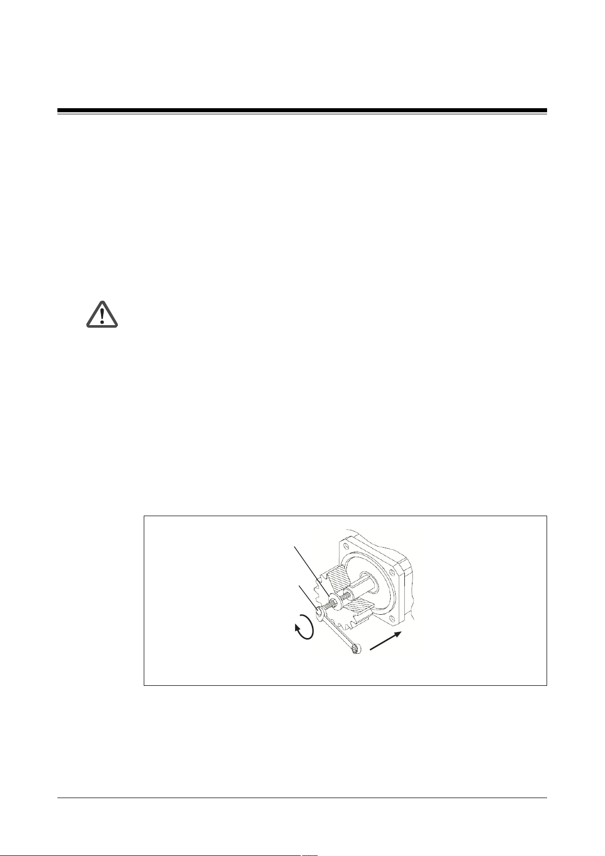
If possible, only use backlash-free, frictionally engaged chucks or clutches.
Use the tightening thread provided in the motor shaft to tighten the clutches, gears or
belt pulleys and, if possible, warm up the drive elements. Do not use excessive force as
this will damage bearings, feedback and the motor shaft.
Spacing washer
Tightening thread
Fig. 6-1: Tightening thread in the motor shaft
Please note:
• Align the clutch correctly
Misalignment can cause undue vibration and can damage the ball bearings and
clutch!
6-2 Operating Manual: PMCtendo AC
Page 25

• Mechanical overdefinition of the motor shaft bearing should be avoided
A rigid clutch and/or an external additional bearing (e.g. in the gear unit) can cause
excess mechanical stress on the motor shaft.
• Do not fasten or attach temperature-sensitive components to the motor
CAUTION!
Burns
Contact with the motor surface during operation will result in injury.
During operation, the surface temperature of the servo motor can exceed 65 °C!
Safety measures should be put in place to protect against contact during operation,
whether accidental or intentional.
Operating Manual: PMCtendo AC 6-3
Page 26

Installation
Notes
6-4 Operating Manual: PMCtendo AC
Page 27

Wiring
General requirements
Secure the site in accordance with the regulations (barrier, warning signs etc.). Wiring
may only be carried out by qualified personnel.
• Please refer to the information and specifications stated in the operating manual of the
servo amplifier you are using.
CAUTION!
Uncontrolled movements of the servo motor will result in injury
Incorrect wiring of the servo motor and/or motor feedback can trigger uncontrolled
movements and result in material and/or personal injury.
• If necessary, consider the trailing capability of the cables you are using.
Cabling
It is possible to differentiate between cables according to their function. The following
groups exist:
• Group 1: Data and supply lines for DC voltages below 60 V and AC voltages
below 25 V
• Group 2: Data and supply lines for DC voltages from 60 V to 400 V and AC voltages
from 25 V to 400 V.
• Group 3: Supply lines above 400 V
Cabling inside buildings:
• The cable groups listed above should be laid separately.
• Cables of the same group can be laid within the same cable duct.
• Cables from group 1 and group 2 should be laid in separate groups or in cable ducts
• Cables from group 1 and group 3 should be laid in separate groups or in cable ducts
• Data lines and control lines should be laid as close as possible to an earthed surface.
Cable cross sections
Please refer to the information stated in the operating manual of the servo amplifier you
are using. The cable cross sections you select should depend on the current supplied by
the servo amplifier.
which are at least 10 cm apart.
which are at least 50 cm apart.
Operating Manual: PMCtendo AC 7-1
Page 28
Wiring
Earthing, shielding and EMC
• On the servo motors, the connection to PE is established via the supply voltage cable
(see section entitled “Connections for supply voltage, thermal switch and holding
brake”).
• If necessary, use a toroidal core for the supply voltage cable, or a motor throttle close
to the servo amplifier. Please refer to the information stated in the operating manual
of the servo amplifier you are using.
• You will need shielded cable for data and control lines.
- Earth the cable shield connection on both sides (e.g. on a bus bar).
- If you are using longer cables and there is the possibility of transient currents, these
can be prevented by using equipotential bonding cables. If you are unable to use
equipotential bonding cables, connect the shield at one end.
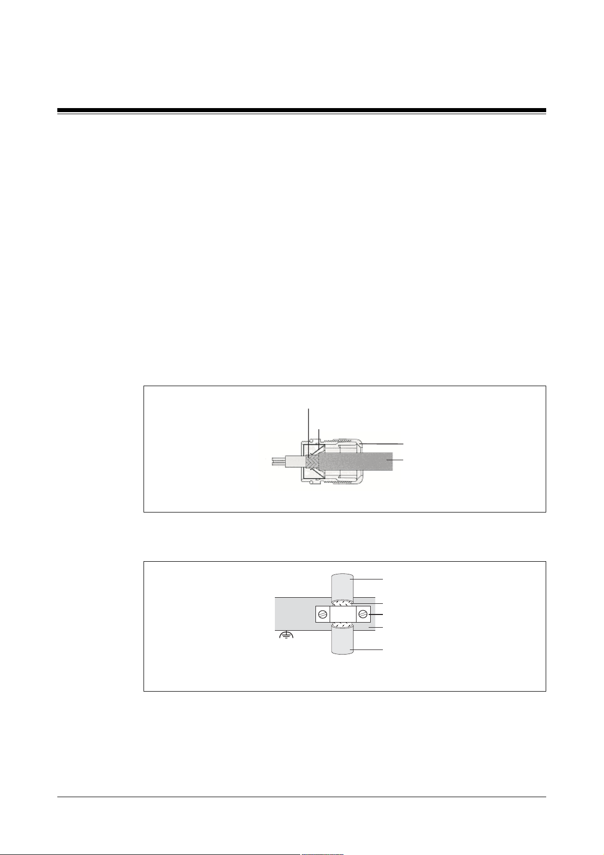
• Shields should be connected over a wide surface area (low impedance), using
metallised connector housings or EMC-compliant cable screw connections. Use the
EMC cable screw connection supplied with the unit.
Cable shield
EMC contact surface
Housing
Cable
Fig. 7-1: EMC screw connection
• An appropriate connection material (e.g. shielded terminals) should be used to
connect the cable shield to the earth bar or bus bar.
Cable
Cable shield
Shielded terminal
Earth bar or
bus bar
Cable
Fig. 7-2: Earthing the cable shield (example)
7-2 Operating Manual: PMCtendo AC
Page 29
Pin assignment and connection
The sections below describe all the connections on a PMCtendo AC servo motor plus
their layout. The connections that your servo motor actually has at its disposal will
depend on the code stated in the order reference (see section entitled “Overview”).
INFORMATION
Only used shielded cable. Pre-assembled cable in various lengths and cross sections is
available from Pilz.
Motor feedback connections
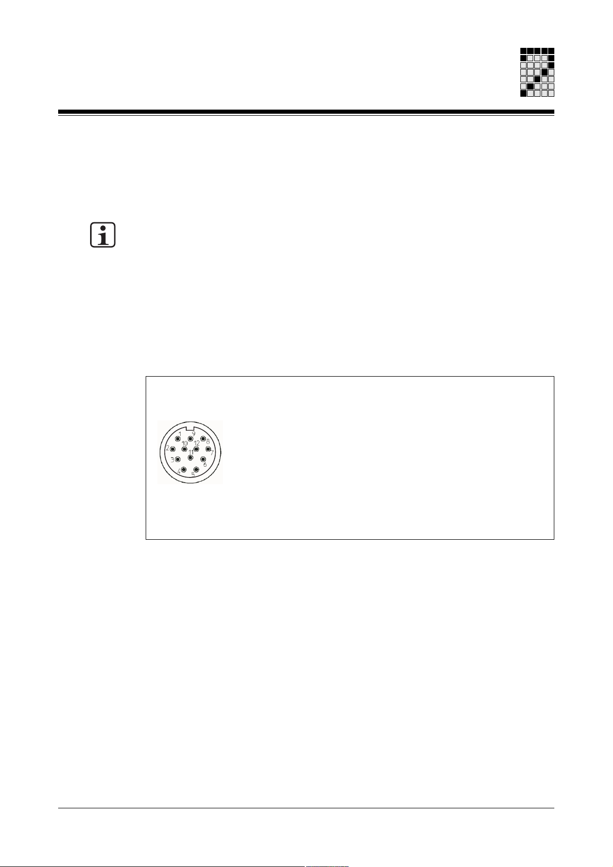
Resolver
To connect the resolver (see Fig. 7-3) to the servo amplifier you will need a cable with a
layout as shown in Fig. 7-4.
Round connector
12-pin, male
1: S1 (Cos1)
2: S2 (Sin1)
3: S4 (Sin2)
4: n.c.
5: n.c.
6: S3 (Cos2)
7: R1 (Ref1)
8: Internal shield
9: Thermal switch
10: Thermal switch
11: R2 (Ref2)
12: n.c.
Fig. 7-3: Pin assignment of the round resolver connector
n.c. = not connected
Operating Manual: PMCtendo AC 7-3
Page 30
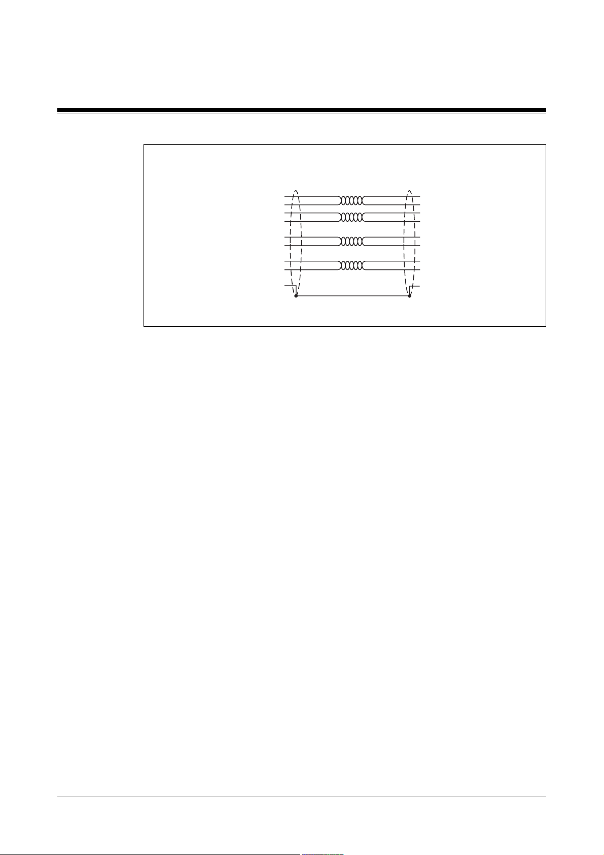
Wiring
Resolver (servo motor)
12-pin round connector, female
11
10
2
3
1
6
7
9
8
S2 (Sin1)
S4 (Sin2)
S1 (Cos1)
S3 (Cos2)
R1 (Ref1)
R2 (Ref2)
Thermal switch
Thermal switch
Shield
Fig. 7-4: Connection cable for resolver
Shield
S2 (Sin1)
S4 (Sin2)
S1 (Cos1)
S3 (Cos2)
R1 (Ref1)
R2 (Ref2)
Thermal switch
Thermal switch
Shield
Cable features:
• Round connector type:
- M23 connector (e.g. made by Intercontec), 12-pin
• Cable cross section and cable runs:
- Depend on the requirements of the servo amplifier you are using
Servo amplifier
7-4 Operating Manual: PMCtendo AC
Page 31
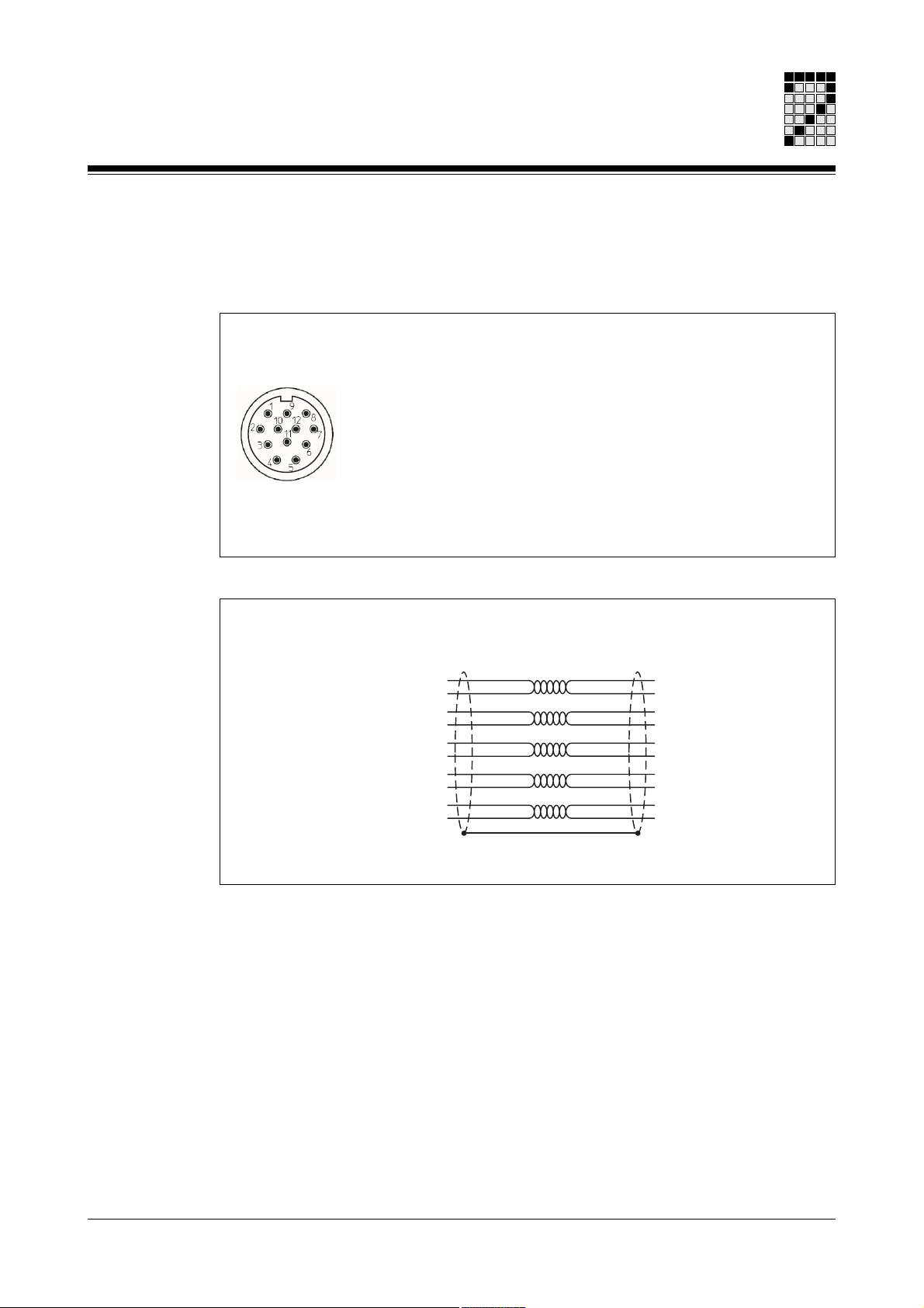
Hiperface encoder
To connect the Hiperface rotary encoder (see Fig. 7-5) to the servo amplifier you will
need a cable with a layout as shown in Fig. 7-6.
Round connector
12-pin, male
1: Us (7 ... 12 V)
2: GND
3: REFSIN
4: REFCOS
5: Data + (RS485)
6: Data - (RS485)
7: + SIN
8: + COS
9: n.c.
10: n.c.
11: Thermal switch
12: Thermal switch
n.c. = not connected
Fig. 7-5 Pin assignment of the round Hiperface connector
Hiperface rotary encoder (servo motor)
12-pin round connector, female
11
12
1
2
7
3
8
4
5
6
Shield
Us (7 ... 12 V)
GND
+ SIN
REFSIN
+ COS
REFCOS
Data + (RS485)
Data - (RS485)
Thermal switch
Thermal switch
Fig. 7-6: Connection cable for Hiperface rotary encoder
Cable features:
• Round connector type:
- M23 connector (e.g. made by Intercontec), 12-pin
• Cable cross section and cable runs:
- Depend on the requirements of the servo amplifier you are using
Servo amplifier
Us (7 ... 12 V)
GND
+ SIN
REFSIN
+ COS
REFCOS
Data + (RS485)
Data - (RS485)
Thermal switch
Thermal switch
Operating Manual: PMCtendo AC 7-5
Page 32

Wiring
Connections for supply voltage, thermal switch and holding brake
General
If you are using a cable that incorporates the wires for the holding brake, the wires for
the holding brake must be shielded.
Terminal box on servo motors AC1 and AC2
To supply the voltage to the servo motor (see Fig. 7-7) via the servo amplifier you will
need a cable with a layout as shown in Fig. 7-8.
INFORMATION
The thermal switch is dual wired. It is carried in the motor feedback cable (see sections
entitled “Resolver” and “Hiperface rotary encoder”), as well as the supply voltage cable.
Connection terminals
Supply voltage for servo motor:
U: Phase U
V: Phase V
W: Phase W
Thermal switch:
BR: Thermal switch
BR2: Thermal switch
PE: Earth connector
Holding brake (optional):
Red: + 24 VDC
Blue: 0 V
Fig. 7-7: Pin assignment within the terminal box (servo motors AC1 and AC2)
7-6 Operating Manual: PMCtendo AC
Page 33

Connection cable (servo motor) Servo amplifier
PE
BR
BR2
1
3
4
Shield
Phase U
Phase W
Phase V
Earth conductor
Thermal switch
Thermal switch
Holding brake
+ 24 VDC
0 VDC
Fig. 7-8: Connection cable for the terminal box (servo motors AC1 and AC2)
Phase U
Phase W
Phase V
Earth conductor
Thermal switch
Thermal switch
Holding brake
+ 24 VDC
[1] Depends on the servo amplifier you are using
Cable features:
• Cable cross section: max. 14 mm
- Wires for supply voltage: max. 3 x 2.5 mm
- Wire for earth conductor PE: max. 1 x 2.5 mm
- Wires for thermal switch: max. 2 x 1 mm
- Wires for holding brake: max. 2 x 1 mm
2
2
2
2
• Cable runs:
- Depend on the requirements of the servo amplifier you are using
[1]
0 VDC
Operating Manual: PMCtendo AC 7-7
Page 34

Wiring
Terminal box on servo motors AC3 and AC4
To supply the voltage to the servo motor (see Fig. 7-9) via the servo amplifier you will
need a cable with a layout as shown in Fig. 7-10.
INFORMATION
Please note that the thermal switch connection is only available via the motor feedback
cable (see sections entitled “Resolver” and “Hiperface rotary encoder”).
Connection terminals Supply voltage for servo motor:
U: Phase U
V: Phase V
W: Phase W
Thermal switch:
BR: Not connected
BR2: Not connected
PE: Earth conductor
Holding brake (optional):
Red: + 24 VDC
Blue: 0 V
Fig. 7-9: Pin assignment within the terminal box (servo motors AC3 and AC4)
Connection cable (servo motor) Servo amplifier
PE
1
3
4
Shield
Phase U
Phase W
Phase V
Earth conductor
Holding brake
+ 24 VDC
0 VDC
Phase U
Phase W
Phase V
Earth conductor
Holding brake
+ 24 VDC
0 VDC
Fig. 7-10: Connection cable for the terminal box (servo motors AC3 and AC4)
Cable features:
• Cable cross section: max. 14 mm
- Wires for supply voltage: max. 3 x 2.5 mm
- Wire for earth conductor PE: max. 1 x 2.5 mm
- Wires for holding brake: max. 2 x 1 mm
2
2
2
• Cable runs:
- Depend on the requirements of the servo amplifier you are using
7-8 Operating Manual: PMCtendo AC
Page 35

Round connector for servo motors AC1 and AC2
Round connectors are used when I0 < 20 A. To connect the servo motor (see Fig. 7-11)
to the servo amplifier you will need a cable with a layout as shown in Fig. 7-12.
INFORMATION
The thermal switch is dual wired. It is carried in the motor feedback cable (see sections
entitled “Resolver” and “Hiperface rotary encoder”), as well as the supply voltage cable.
Round connector
8-pin, male
Supply voltage
Servo motor:
1: Phase U
Holding brake:
A: + 24 VDC
B: 0 VDC
3: Phase W
4: Phase V
Thermal switch:
C: Thermal switch
PE: Earth conductor
Fig. 7-11: Pin assignment of the round connector (servo motors AC1 and AC2)
D: Thermal switch
Connection cable (servo motor)
8-pin round connector, female
PE
1
3
4
C
D
A
B
Shield
Phase U
Phase W
Phase V
Earth conductor
Thermal switch
Thermal switch
Holding brake
+ 24 VDC
0 VDC
Servo amplifier
Phase U
Phase W
Phase V
Earth conductor
Thermal switch
Thermal switch
Holding brake
+ 24 V DC
0 V DC
[1]
Fig. 7-12: Connection cable for the round connector (servo motors AC1 and AC2)
[1] Depends on the servo amplifier you are using
Cable features:
• Round connector type:
- Connector with 28 mm diameter (e.g. made by Intercontec), 8-pin
• Cable cross section:
- Wires for supply voltage: max. 3 x 2.5 mm
- Wire for earth conductor PE: max. 1 x 2.5 mm
Operating Manual: PMCtendo AC 7-9
2
2
Page 36

Wiring
- Wires for thermal switch: max. 2 x 1 mm
- Wires for holding brake: max. 2 x 1 mm
• Cable runs:
- Depend on the requirements of the servo amplifier you are using
Round connector for servo motors AC3 and AC4
Round connectors are used when I0 < 20 A. To connect the servo motor (see Fig. 7-13)
to the servo amplifier you will need a cable with a layout as shown in Fig. 7-14.
INFORMATION
Please note that the thermal switch connection is only available via the motor feedback
cable (see sections entitled “Resolver” and “Hiperface rotary encoder”).
Round connector
8-pin, male
Supply voltage
Servo motor:
1: Phase U
3: Phase W
4: Phase V
PE: Earth conductor
2
2
Holding brake:
A: + 24 VDC
B: 0 VDC
Thermal switch:
C: Not connected
D: Not connected
Fig. 7-13: Pin assignment of the round connector (servo motors AC3 and AC4)
Connection cable (servo motor)
8-pin round connector, female
Phase U
Phase W
Phase V
Earth conductor
Holding brake
+ 24 VDC
0 VDC
Fig. 7-14: Connection cable for the round connector (servo motors AC3 and AC4)
PE
1
3
4
A
B
Shield
Phase U
Phase W
Phase V
Earth conductor
Holding brake
+ 24 VDC
Cable features:
• Round connector type:
- Connector with 28 mm diameter (e.g. made by Intercontec), 8-pin
Servo amplifier
0 VDC
7-10 Operating Manual: PMCtendo AC
Page 37

• Cable cross section:
- Wires for supply voltage: max. 3 x 2.5 mm
- Wire for earth conductor PE: max. 1 x 2.5 mm
- Wires for thermal switch: max. 2 x 1 mm
- Wires for holding brake: max. 2 x 1 mm
• Cable runs:
- Depend on the requirements of the servo amplifier you are using
Connecting the supply voltage
Never remove or attach the connections while voltage is applied.
WARNING!
Electric shock
Contact with live parts will result in serious injury.
Switch off the supply voltages to all connected devices!
Hazardous values may still be present up to 5 minutes after the voltage is switched off,
due to residual charges in the servo amplifier’s capacitors. When the shaft is rotating
(externally driven, running down) the motor acts as a generator. This means that
hazardous voltages will be present at the connection terminals.
The direction of rotation of the servo motor is determined by the phase sequence of the
supply voltage. The servo motor is designed so that the motor shaft rotates to the right
when it is connected as shown in Fig. 7-15.
Any change to the direction of rotation must be made via the servo amplifier. Servo
amplifiers can change the direction of rotation of the servo motor by changing the phase
sequence electronically.
2
2
2
2
L1 L2 L3
Servo amplifier
L1
L2
L3
Direction
of rotation
A-end
View direction
Fig. 7-15: “Clockwise” direction of rotation, viewed from the drive end (principle)
Operating Manual: PMCtendo AC 7-11
(drive end)
U
V
W
right
Servo motor
U
V
W
B-end
Page 38

Wiring
Connecting the holding brake
The holding brake can be controlled directly by the servo amplifier. In this case, the
braking action is suppressed within the servo amplifier. No additional wiring is required
within the braking circuit. Servo amplifiers from Pilz are fitted with a brake control as
standard.
If the holding brake is not controlled by the servo amplifier, the brake circuit must be
fitted with a suppression device through additional wiring (e.g. varistor).
Suppression device
(e.g. varistor)
Power supply
+24 VDC
0 VDC
Fig. 7-16: Suppression device within the holding brake circuit (principle)
+24 VDC
M
0 VDC
If the operation of the holding brake is to include personal safety, an extra N/O contact is
required for the holding brake within the brake circuit, as well as the additional
suppression device (e.g. varistor). Control of this N/O contact must be safety-related.
External safety-related control
of N/O contact
Power supply
Servoregler
Fig. 7-17: Safety-related control of the holding brake circuit (principle)
+24 VDC
0 VDC
+24 VDC
M
0 VDC
INFORMATION
The holding brake is operated with DC voltage (24 VDC). When you connect it, make
sure that the polarity is correct.
7-12 Operating Manual: PMCtendo AC
Page 39

Commissioning
General requirements
Secure the site in accordance with the regulations (barrier, warning signs etc.).
Commissioning may only be carried out by qualified personnel.
• Please refer to the information and specifications stated in the operating manual of the
servo amplifier you are using.
• During commissioning, make sure that no personal injury and/or material damage can
occur, even if the drive moves unintentionally.
CAUTION!
Uncontrolled movements of the servo motor will result in injury
Incorrect wiring of the servo motor and/or motor feedback can trigger uncontrolled
movements and result in material and/or personal injury.
Operating Manual: PMCtendo AC 8-1
Page 40

Commissioning
Check installation and wiring
Installation
Check the installation and orientation of
the servo motor.
- - -
Check the drive elements (clutch, gear unit,
belt pulley) to ensure that they are firmly
seated and set up correctly.
Check that the motor surface is protected
against contact during operation, whether
accidental or intentional.
Check that the rotor of the servo motor can
rotate freely.
WARNING!
Risk of life-threatening injury when operating the
servo motor
Servo motors with feather key must not be operated
unless the drive pulley is fully installed! Make sure
that the drive connection between the shaft and the
machine has been fully installed.
CAUTION!
Burns
During operation, the surface temperature of the
servo motor can exceed 65 °C!
INFORMATION
If a holding brake is present, this must first be
released (see “Holding brake”).
Check the polarity!
8-2 Operating Manual: PMCtendo AC
Page 41

Wiring
Check that the units are earthed correctly.
Check that all live parts are safely
protected against contact during operation,
whether accidental or intentional.
WARNING!
Electric shock
Life-threatening voltages are present at the supply
voltage connections.
Check the wiring and the connections to
the servo motor, brake and servo amplifier.
Check the direction of rotation of the servo
motor.
Holding brake
Check the function of the holding brake.
Then carry out all the other checks required specifically for your plant.
Commissioning the drive unit
CAUTION!
Uncontrolled movements of the servo motor will result
in injury
Incorrect wiring of the servo motor and/or motor
feedback can trigger uncontrolled movements and
result in material and/or personal injury.
Activate the servo motor via the servo amplifier.
Apply the 24 V control voltage:
The holding brake must release.
Check the polarity!
Do not commission the drive unit (servo motor and servo amplifier) until you have
performed all the checks.
When commissioning, please note the following:
• Make sure that you follow the commissioning instructions for the servo amplifier you
are using.
• With multi-axis systems, each drive unit should be commissioned separately.
Operating Manual: PMCtendo AC 8-3
Page 42

Commissioning
Troubleshooting guidelines
The table below only lists the errors that directly affect the servo motor. You should also
refer to the error messages for the servo amplifier you are using. Multi-axis systems with
higher level position control systems may also have additional error causes.
Fault
Motor does not
rotate
Motor spins
(positive
feedback)
Motor vibrates
Error message
Output stage
error
Error message
Feedback
Error message
Motor
temperature
Potential error cause
• Servo amplifier has not been enabled
• Set point cable is broken
• Motor phases transposed
(incorrect phase sequence)
• Brake has not been released
• Drive is mechanically blocked
• Torque is too low
• Incorrect feedback offset
• Motor phases transposed
(cyclically transposed, correct phase
sequence)
• Shield on the feedback line
is broken
• Invalid control parameters
• Motor cable has a short
circuit or earth fault
• Motor has a short
circuit or earth fault
• Feedback connector is not inserted
correctly
• Feedback line is broken,
crushed or similar
• Thermal switch has energised
• Connection to the thermal switch
is broken
Remedy
• Apply the enable signal
from the servo amplifier
• Check the set point cable
• Connect the motor phases correctly
• Check the brake control
• Check the mechanics
Lift the current limitation in the servo
amplifier
or
Use a larger motor or servo amplifier
• Check feedback offset and
set the parameters correctly
• Change the direction of rotation
in the servo amplifier
• Connect the motor phases correctly
• Change the feedback line
• Adjust the controller
• Swap the cable
• Swap the motor
• Check the plug-in connection
• Check the wiring
Wait for the motor to cool down, then:
• Check the connector and cable
• Possibly use a new cable
Holding brake
doesn’t catch
8-4 Operating Manual: PMCtendo AC
• Required holding torque is too
high
• Holding brake is defective
• Motor shaft axially overloaded
• Check the specification of the
holding brake
• Swap the motor
• Check the axial load and
reduce if necessary,
also swap the motor because the
bearings are damaged
Page 43

Maintenance and Repair
General guidelines for maintenance and repair
Before starting maintenance or repair work, please note the following:
• Maintenance and repair work may only be carried out by qualified personnel.
• Make sure that the plant or machine is isolated in accordance with the regulations.
• The plant or machine should be safeguarded against inadvertent reconnection.
• Check that the voltage is disconnected.
WARNING!
Electric shock
Control and power connections may carry voltage, as residual charges in the servo
amplifier’s capacitors may still show hazardous values up to 5 minutes after the
voltage is switched off.
• A servo motor may only be repaired by Pilz GmbH & Co. KG. If the servo motor is
opened without authorisation and handled improperly the warranty will be rendered
invalid.
Operating Manual: PMCtendo AC 9-1
Page 44

Maintenance and Repair
Maintenance intervals
If suitably installed, the servo motors are largely maintenance free. As operating
conditions can vary greatly, maintenance intervals must be adapted to suit the local
conditions (e.g. pollution degree, switch on frequency, load).
Maintenance interval
Regularly
Every 500 operating hours,
or
min. once per year
Every 2500 operating hours,
or
min. once per year
After 20000 operating hours
(under rated conditions)
What to do?
Clean the servo motor
Check the electrical and mechanical
connections and retighten if
necessary
Check that the servo motor is
running quietly and, if necessary,
check the installation; if necessary,
change the servo motor
Check the noise level of the ball
bearings and, if there is any
deterioration, check the installation;
if necessary, send in the servo motor
to have the ball bearings changed
Check the noise level of the ball
bearings and, if necessary, send in
the servo motor to have the ball
bearings changed
Send in the servo motor to have the
ball bearings changed
What to consider?
Cleaning intervals should depend on
the local pollution degree
• Let the motor cool down
• Do not use solvents
• Select a cleaning method that’s
appropriate for the servo motor’s
protection type, otherwise the
ingress of liquid could damage the
motor.
- - -
See section entitled “Changing the
servo motor”
The ball bearings may only be
exchanged by Pilz GmbH & Co. KG!
(refer also to the section entitled
“Changing the servo motor”)
9-2 Operating Manual: PMCtendo AC
Page 45
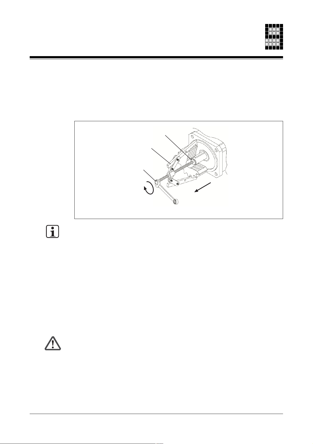
Changing the servo motor
When uninstalling you must use the tightening thread provided in the motor shaft and, if
possible, warm up the drive elements. Do not use excessive force as this will damage
bearings, feedback and the motor shaft. Use a suitable extraction tool.
Fig. 9-1: Tightening thread in the motor shaft
INFORMATION
You must read the information in the section entitled “General guidelines for
maintenance and installation” before changing the servo motor.
Spacing washer
Extraction tool
Tightening thread
Please note the following when changing the motor:
• If servo motors have been in storage for longer than 2 years, the holding brake must
be resurfaced before the servo motor is used.
- Only resurface the holding brake while the servo motor is uninstalled!
- With the holding brake in a closed condition, turn the servo motor by hand for
approx. 50 revolutions.
The holding brake is now ready for operation.
• Please refer to the information in the chapter entitled “Installation”, under “Installing
the servo motor”.
• On servo axes with indirect position measuring via the encoder, the reference to the
machine coordinate system is lost.
CAUTION!
Injury due to unintended axis movements!
Once the unit has been exchanged, restore the reference to the machine coordinate
system.
Operating Manual: PMCtendo AC 9-3
Page 46

Maintenance and Repair
Notes
9-4 Operating Manual: PMCtendo AC
Page 47

Glossary
C
Constant standstill current Current (sinusoidal effective value) that is required to generate constant
standstill torque M0 when speed n = 0
Abbreviation: I
0
Unit: A
Constant standstill torque Torque that can be applied for an unlimited time when speed n = 0
Abbreviation: M
0
Unit: Nm
M
Mass moment of inertia Mass moment of inertia of the servo motor (with/without holding brake)
1 kgcm2 = 1 x 10⁻⁴ kgm
2
Abbreviation: J
Unit: kgm
2
P
Peak current Short-term maximum permitted current (sinusoidal effective value), at
which the servo motor is undamaged
Abbreviation: I
max
Unit: A
Peak torque Torque produced at peak current I
Abbreviation: M
max
max
Unit: Nm
Operating Manual: PMCtendo AC 10-1
Page 48

Glossary
R
Rated current Current (sinusoidal effective value) consumed by the servo motor when
subject to rated speed nN and rated torque M
N
Abbreviation: I
N
Unit: A
Rated power Mechanical output at the servo motor shaft when it is subject to rated
torque MN at rated speed n
Abbreviation: P
N
N
Unit: W
Rated speed Speed at which the rated torque MN can be achieved as a minimum, at
rated voltage U
Abbreviation: n
Unit: min
Rated torque Torque that can be applied for an unlimited time at rated speed n
Abbreviation: M
N
N
-1
N
N
Unit: Nm
Rated voltage Output voltage (sinusoidal effective value) of servo amplifier
Abbreviation: U
N
Unit: V
T
Thermal time constant When there is a load change, the period after which 63 % of the
corresponding temperature change is achieved
After 5 x tth the temperature change is complete.
Abbreviation: T
th
Unit: min
Torque constant Factor for the relationship between current and torque.
When Kt = 1Nm/A, the servo motor generates torque of 1Nm at 1 A
current (sinusoidal effective value)
Abbreviation: K
T
Unit: Nm/A
10-2 Operating Manual: PMCtendo AC
Page 49

Appendix
Changes in the documentation
Changes in Version 21 894-01:
Old
page
- - -
Changes in Version 21 894-02:
Old
page
12-8 to
12-37
New
page
- - -
New
page
12-8 to
12-37
Change
The operating manual was completely revised
Change
Technical details updated
Operating Manual: PMCtendo AC 11-1
Page 50

Appendix
Notes
11-2 Operating Manual: PMCtendo AC
Page 51

Technical Details
General technical details
Electrical data
Supply voltage
Type M
Type H
Current consumption
Current form
Insulation material class
(IEC 60085)
Environmental data
Protection type (IEC 60034-5)
without shaft seal
with shaft seal motor size 21 ... 25
with shaft seal
Mounting position
(IEC 60034-7)
Ambient temperature
(IEC 60034-1)
Storage temperature
(IEC 60034-1)
Cooling
(IEC 60034-6)
Condensation
Installation height
Shaft end
Option with feather key groove
Balancing (DIN ISO 8821)
Feather key groove assembly
Option without feather key groove
Fit
(IEC 60072-1)
Flange
Design
(IEC 60034-7)
Fit
(DIN 42948)
Accuracy
(DIN 42955)
230 V
400 V
see section entitled “Performance data”
Sinusoidal
H
Performance measurement to F
IP44
IP44
IP65
IM B5, IM V1, IM V3
+5 ... +40 °C
-15 ... +40 °C
Self-cooling IC410
Not permitted
≤≤
≤ 1000 m above sea level
≤≤
With feather key
With half feather key
DIN 6885-1
Smooth shaft
k6
IM B5
j6
Increased
Operating Manual: PMCtendo AC 12-1
Page 52

Technical Details
Mechanical data
Weight
Dimensions
The names of products, goods and technologies used in this manual are trademarks of the respective companies.
See section entitled “Mechanical data”
See section entitled “Dimensions”
12-2 Operating Manual: PMCtendo AC
Page 53

Derating
When dimensioning the drive you should take into account the factor K
calculated from the factors K
The factor K
can be used to calculate the permitted torque:
total
Derating diagram: Installation height
120
100
[%]
N
80
60
40
, K
total
temp
= K
and K
height
height
K
Permitted torque = K
:
duty
* K
* K
temp
* Rated torque M
total
duty
. It is
total
N
K
height
Rated torque M
20
0
500 1000 1500 2000 2500 3000 3500
Installation height [m above sea level]
Fig. 12-1: Permitted torque in relation to installation height
Example:
Installation height = 2000 m above sea level
According to the diagram (Fig. 12-1), at this installation height the permitted torque is
approx. 90 % of the rated torque MN.
This gives the following for factor K
K
= 0.9.
height
height
:
Operating Manual: PMCtendo AC 12-3
Page 54

Technical Details
Derating diagram: Ambient temperature
140
120
100
[%]
N
80
60
40
Rated torque M
20
0
-20 -10 0 10 20 30 40
Ambient temperature [°C]
K
temp
50 60
Fig. 12-2: Permitted torque in relation to ambient temperature
Example:
Ambient temperature = 50 °C
According to the diagram (Fig. 12-2), at this ambient temperature the permitted torque is
approx. 90 % of the rated torque MN.
This gives the following for factor K
K
= 0.9.
temp
temp
:
12-4 Operating Manual: PMCtendo AC
Page 55
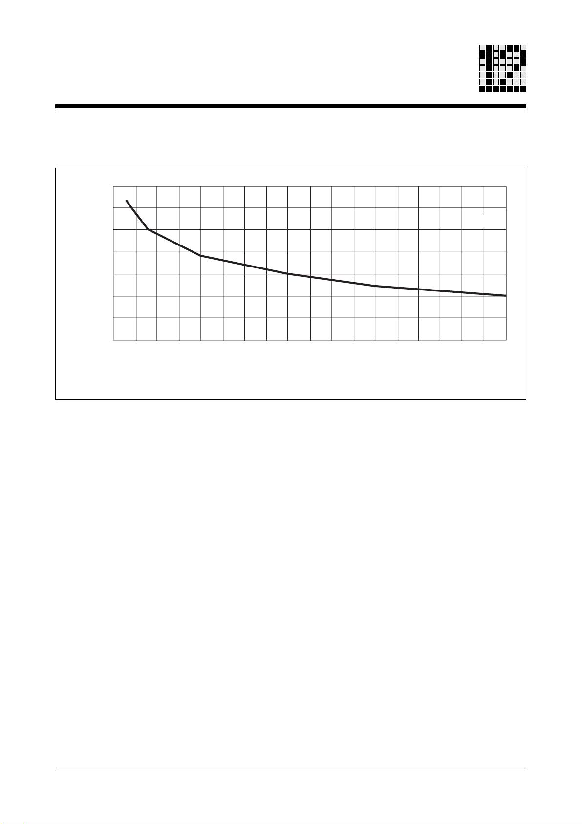
Derating diagram: Operating time
350
300
250
[%]
N
200
150
100
Rated torque M
50
K
duty
0
20 30 40 50 60 70 80
Operating time [%]
Fig. 12-3: Permitted torque in relation to operating time
Example:
Operating time = 70 %
According to the diagram (Fig. 12-3), at this operating time the permitted torque is
approx. 125 % of the rated torque MN.
This gives the following for factor K
K
= 1.25.
duty
duty
90 100
:
Operating Manual: PMCtendo AC 12-5
Page 56

Technical Details
Type-specific technical details
Key to the designations used in the table header
The table below contains the key to the designations used in the table header for the
performance data (see section entitled “Performance data”).
Designation
used in the
table header
Msize
UN [V]
Mmax [Nm]
nN [min-1]
M0 [Nm]
I0 [A]
IN [A]
Imax [A]
nmax [min-1]
2p
Uin [V]
Tth [min]
KE [Vs]
KT [Nm/A]
R20 [Ohm]
L [mH]
Unit
- - V
Nm
min-1
Nm
A
A
A
min-1
- - V
min
Vs
Nm/A
Ohm
mH
Key
Motor size
Ratedvoltage
Peak torque
Rated speed
Constant standstill torque
Constant standstill current
Rated current
Peak current
Peak speed
Number of poles
Regenerated voltage
Thermal time constant
Voltage constant
Torque constant
Winding resistance phase/phase
Winding inductance
Table 12-1: Key for performance data
12-6 Operating Manual: PMCtendo AC
Page 57

The table below contains the key to the designations used in the table header for the
mechanical data (see section entitled “Mechanical data”).
Designation
Unit
Key
used in the
table header
Msize
BR
BrValues
J [ kgcm²]
L [mm]
MFB
mNet
Fan
Table 12-2: Key for mechanical data
- - -
- - -
- - kgcm²
mm
- - kg
- - -
Motor size
Brake
Brake connection values
Mass moment of inertia
Overall motor length
Motor feedback
Net weight
Separate ventilation
The table below contains the key to the designations used in the table header for the
dimensions (see section entitled “Dimensions”).
Designation
Unit
Key
used in the
table header
Msize
a1 [mm]
a2 [mm]
b1 [mm]
c1 [mm]
d [mm]
e1 [mm]
f1 [mm]
l [mm]
l1 [mm]
l2 [mm]
s1 [mm]
s2 [mm]
t [mm]
u [mm]
- - mm
mm
mm
mm
mm
mm
mm
mm
mm
mm
mm
mm
mm
mm
Motor size
Motor flange
Motor flange
Centre diameter
Flange strength
Shaft diameter information
Pitch circle diameter
Pitch circle collar
Wavelength
Feather key spacing
Feather key length
Screw hole
Shaft centering thread
Shaft diameter with feather key
Feather key width
Table 12-3: Key for dimensions
Operating Manual: PMCtendo AC 12-7
Page 58

Performance data
Operating Manual: PMCtendo AC 1
61 400 V 2,00 Nm 1,80 Nm 8,80 Nm 1,20 A
61 400 V 2,00 Nm 1,70 Nm 8,80 Nm 1,60 A
61 400 V 2,00 Nm 1,50 Nm 8,80 Nm 2,50 A
54 400 V 2,80 Nm 1,90 Nm 6,60 Nm 3,90 A
53 400 V 1,90 Nm 1,60 Nm 4,80 Nm 1,30 A
53 400 V 1,90 Nm 1,60 Nm 4,80 Nm 1,30 A
53 400 V 1,90 Nm 1,50 Nm 4,80 Nm 1,70 A
53 230 V 1,90 Nm 1,60 Nm 4,80 Nm 2,30 A
52 400 V 1,30 Nm 1,00 Nm 3,30 Nm 1,20 A
52 400 V 1,30 Nm 1,00 Nm 3,30 Nm 0,90 A
52 230 V 1,30 Nm 1,00 Nm 3,30 Nm 1,50 A
52 230 V 1,30 Nm 0,90 Nm 3,30 Nm 3,10 A
51 400 V 0,60 Nm 0,50 Nm 1,70 Nm 0,40 A
25 400 V 0,70 Nm 0,65 Nm 2,20 Nm 0,89 A
24 400 V 0,50 Nm 0,45 Nm 1,63 Nm 0,64 A
24 230 V 0,50 Nm 0,39 Nm 1,63 Nm 2,22 A
22 400 V 0,25 Nm 0,22 Nm 0,81 Nm 0,32 A
21 400 V 0,13 Nm 0,11 Nm 0,41 Nm 0,17 A
Performance data: PMCtendo AC1
Msize
Technical Details
UN [V]
M0 [Nm]
MN [Nm]
Mmax [Nm]
I0 [A]
1,10 A 5,40 A
3000 rpm 6000 rpm 6 296 V 20 min 0,94 V 1,63 Nm 35,60 Ohm 122,00 mH
1,80 A 10,80 A
1,40 A 7,20 A
6000 rpm 6000 rpm 6 296 V 20 min 0,47 V 0,82 Nm 8,80 Ohm 30,00 mH
4000 rpm 6000 rpm 6 296 V 20 min 0,71 V 1,22 Nm 20,10 Ohm 68,00 mH
1,10 A 3,30 A
2,60 A 9,10 A
3000 rpm 6000 rpm 4 264 V 76 min 0,84 V 1,45 Nm 27,80 Ohm 121,70 mH
6000 rpm 6000 rpm 4 263 V 95 min 0,42 V 0,73 Nm 4,41 Ohm 18,40 mH
1,10 A 3,30 A
3000 rpm 6000 rpm 4 263 V 76 min 0,84 V 1,45 Nm 27,80 Ohm 121,70 mH
1,90 A 5,70 A
1,40 A 4,40 A
3000 rpm 6000 rpm 4 152 V 76 min 0,48 V 0,84 Nm 9,46 Ohm 40,90 mH
4000 rpm 6000 rpm 4 263 V 76 min 0,63 V 1,09 Nm 15,90 Ohm 68,90 mH
0,90 A 3,00 A
4000 rpm 6000 rpm 4 263 V 45 min 0,63 V 1,09 Nm 29,80 Ohm 105,80 mH
0,68 A 2,30 A
3000 rpm 6000 rpm 4 263 V 45 min 0,84 V 1,45 Nm 52,70 Ohm 187,20 mH
2,10 A 7,90 A
1,20 A 3,90 A
6000 rpm 6000 rpm 4 152 V 45 min 0,24 V 0,42 Nm 4,60 Ohm 16,40 mH
3000 rpm 6000 rpm 4 152 V 45 min 0,48 V 0,84 Nm 17,80 Ohm 64,00 mH
0,30 A 1,20 A
3000 rpm 6000 rpm 4 263 V 50 min 0,84 V 1,45 Nm 160,00 Ohm 446,00 mH
0,57 A 2,10 A
0,83 A 2,80 A
3000 rpm 6000 rpm 4 142 V 40 min 0,45 V 0,78 Nm 59,00 Ohm 130,00 mH
3000 rpm 6000 rpm 4 142 V 43 min 0,45 V 0,78 Nm 45,00 Ohm 97,00 mH
0,28 A 1,00 A
1,73 A 7,23 A
3000 rpm 6000 rpm 4 142 V 35 min 0,45 V 0,78 Nm 180,00 Ohm 284,00 mH
6000 rpm 6000 rpm 4 82 V 40 min 0,13 V 0,23 Nm 5,00 Ohm 11,00 mH
0,14 A 0,52 A
3000 rpm 6000 rpm 4 142 V 32 min 0,45 V 0,78 Nm 536,00 Ohm 635,00 mH
IN [A]
Imax [A]
nN [min-1]
nmax [min-1]
2p
Uin [V]
Tth [min]
KE [Vs]
KT [Nm/A]
R20 [Ohm]
L [mH]
2 - 8
Page 59

L [mH]
R20 [Ohm]
KT [Nm/A]
KE [Vs]
Tth [min]
Uin [V]
2p
2 - 9
nmax [min-1]
nN [min-1]
Imax [A]
IN [A]
I0 [A]
Mmax [Nm]
MN [Nm]
3000 rpm 4000 rpm 6 171 V 25 min 0,54 V 0,94 Nm 3,50 Ohm 16,00 mH
4000 rpm 4000 rpm 6 296 V 25 min 0,71 V 1,22 Nm 5,70 Ohm 25,00 mH
3,70 A 18,10 A
2,70 A 14,00 A
4000 rpm 6000 rpm 6 296 V 25 min 0,71 V 1,22 Nm 5,70 Ohm 25,00 mH
3000 rpm 4000 rpm 6 296 V 25 min 0,94 V 1,63 Nm 11,10 Ohm 48,70 mH
2,70 A 14,00 A
2,10 A 10,50 A
2000 rpm 4000 rpm 6 296 V 25 min 1,14 V 2,45 Nm 24,80 Ohm 108,40 mH
1,50 A 7,00 A
4000 rpm 6000 rpm 6 296 V 30 min 0,71 V 1,22 Nm 3,00 Ohm 15,80 mH
3000 rpm 4000 rpm 6 296 V 30 min 0,94 V 1,63 Nm 5,50 Ohm 28,50 mH
4,10 A 20,00 A
3,30 A 15,00 A
3000 rpm 4000 rpm 6 297 V 30 min 0,94 V 1,63 Nm 5,50 Ohm 28,50 mH
3000 rpm 4000 rpm 6 298 V 30 min 0,94 V 1,63 Nm 5,50 Ohm 28,50 mH
3,30 A 15,00 A
3,30 A 15,00 A
4000 rpm 6000 rpm 6 171 V 30 min 0,41 V 0,71 Nm 0,68 Ohm 4,10 mH
4000 rpm 6000 rpm 6 296 V 30 min 0,71 V 1,22 Nm 2,00 Ohm 11,90 mH
9,30 A 46,80 A
5,40 A 27,10 A
3000 rpm 4000 rpm 6 296 V 30 min 0,94 V 1,63 Nm 3,70 Ohm 22,50 mH
6000 rpm 6000 rpm 6 296 V 35 min 0,47 V 0,82 Nm 0,68 Ohm 4,23 mH
4,40 A 20,30 A
9,40 A 49,70 A
3000 rpm 4000 rpm 6 171 V 45 min 0,54 V 0,94 Nm 0,76 Ohm 5,41 mH
4000 rpm 4000 rpm 6 296 V 45 min 0,71 V 1,22 Nm 1,20 Ohm 7,70 mH
8,30 A 39,20 A
11,10 A 50,90 A
3000 rpm 4000 rpm 6 296 V 45 min 0,94 V 1,63 Nm 2,30 Ohm 15,10 mH
3000 rpm 4000 rpm 6 171 V 45 min 0,54 V 0,94 Nm 0,42 Ohm 3,59 mH
6,40 A 29,40 A
15,00 A 63,70 A
4000 rpm 4000 rpm 6 296 V 45 min 0,71 V 1,22 Nm 0,86 Ohm 7,00 mH
8,60 A 49,00 A
M0 [Nm]
UN [V]
Performance data: PMCtendo AC1
Msize
Technical Details
Performance data
62 230 V 4,00 Nm 3,50 Nm 17,10 Nm 4,20 A
62 400 V 4,00 Nm 3,30 Nm 17,10 Nm 3,30 A
62 400 V 4,00 Nm 3,30 Nm 17,10 Nm 3,30 A
62 400 V 4,00 Nm 3,50 Nm 17,10 Nm 2,50 A
62 400 V 4,00 Nm 3,60 Nm 17,10 Nm 1,60 A
63 400 V 6,00 Nm 5,00 Nm 24,40 Nm 4,90 A
63 400 V 6,00 Nm 5,30 Nm 24,40 Nm 3,70 A
63 400 V 6,00 Nm 5,30 Nm 24,40 Nm 3,70 A
63 400 V 6,00 Nm 5,30 Nm 24,40 Nm 3,70 A
64 230 V 8,00 Nm 6,60 Nm 33,10 Nm 11,30 A
64 400 V 8,00 Nm 6,60 Nm 33,10 Nm 6,50 A
64 400 V 8,00 Nm 7,10 Nm 33,10 Nm 4,90 A
65 400 V 10,00 Nm 7,70 Nm 40,50 Nm 12,30 A
73 230 V 11,70 Nm 10,50 Nm 48,00 Nm 12,20 A
73 400 V 11,70 Nm 10,10 Nm 48,00 Nm 9,60 A
73 400 V 11,70 Nm 10,50 Nm 48,00 Nm 7,20 A
74 230 V 15,60 Nm 14,10 Nm 60,00 Nm 16,60 A
74 400 V 15,60 Nm 13,50 Nm 60,00 Nm 9,60 A
Operating Manual: PMCtendo AC 1
Page 60

Performance data
Operating Manual: PMCtendo AC 1
A7 400 V 43,00 Nm 39,10 Nm 139,00 Nm 17,60 A
A9 400 V 54,00 Nm 49,10 Nm 163,00 Nm 22,00 A
A4 400 V 24,00 Nm 21,80 Nm 89,00 Nm 9,80 A
A5 400 V 30,00 Nm 26,20 Nm 99,00 Nm 18,40 A
A2 400 V 12,00 Nm 10,10 Nm 41,00 Nm 12,80 A
A4 400 V 24,00 Nm 20,90 Nm 89,00 Nm 14,70 A
76 400 V 23,40 Nm 20,10 Nm 92,00 Nm 19,10 A
76 400 V 23,40 Nm 21,10 Nm 92,00 Nm 14,30 A
74 400 V 15,60 Nm 14,10 Nm 60,00 Nm 9,60 A
75 230 V 19,50 Nm 17,60 Nm 80,00 Nm 20,70 A
74 400 V 15,60 Nm 14,10 Nm 60,00 Nm 12,70 A
Performance data: PMCtendo AC1
Msize
Technical Details
UN [V]
M0 [Nm]
MN [Nm]
Mmax [Nm]
I0 [A]
16,00 A 56,70 A
20,00 A 66,50 A
2000 rpm 3000 rpm 6 296 V 65 min 1,41 V 2,45 Nm 0,55 Ohm 7,60 mH
2000 rpm 4000 rpm 6 296 V 70 min 1,41 V 2,45 Nm 0,39 Ohm 5,90 mH
16,00 A 60,60 A
8,90 A 36,30 A
2000 rpm 3000 rpm 6 296 V 55 min 1,41 V 2,45 Nm 1,10 Ohm 13,60 mH
3000 rpm 4000 rpm 6 296 V 60 min 0,94 V 1,63 Nm 0,37 Ohm 5,30 mH
10,70 A 43,60 A
12,80 A 54,50 A
3000 rpm 4000 rpm 6 296 V 50 min 0,94 V 1,63 Nm 1,70 Ohm 20,50 mH
3000 rpm 4000 rpm 6 296 V 55 min 0,94 V 1,63 Nm 0,55 Ohm 6,80 mH
16,40 A 75,20 A
12,90 A 56,40 A
4000 rpm 4000 rpm 6 296 V 55 min 0,71 V 1,22 Nm 0,35 Ohm 2,90 mH
3000 rpm 4000 rpm 6 296 V 55 min 0,94 V 1,63 Nm 0,64 Ohm 5,40 mH
18,70 A 84,90 A
8,60 A 36,80 A
3000 rpm 4000 rpm 6 296 V 45 min 0,94 V 1,63 Nm 1,61 Ohm 13,00 mH
3000 rpm 4000 rpm 6 171 V 50 min 0,54 V 0,94 Nm 0,32 Ohm 2,84 mH
11,00 A 36,80 A
3000 rpm 4000 rpm 6 296 V 45 min 0,94 V 1,63 Nm 1,61 Ohm 13,00 mH
IN [A]
Imax [A]
nN [min-1]
nmax [min-1]
2p
Uin [V]
Tth [min]
KE [Vs]
KT [Nm/A]
R20 [Ohm]
L [mH]
2 - 10
Page 61

Fan
mNet
MFB
11
2 -
L [mm]
J [ kgcm²]
BrValues
no 0,21 kgcm² 149 mm Resolver 2-pole 1.650 g no
no 0,16 kgcm² 129 mm Resolver 2-pole 1.350 g no
no 0,32 kgcm² 189 mm Resolver 2-pole 2.250 g no
no 0,32 kgcm² 190 mm Resolver 2-pole 2.250 g no
no 0,38 kgcm² 209 mm Resolver 2-pole 2.550 g no
24VDC/0,51A/3,5Nm 1,40 kgcm² 238 mm Resolver 2-pole 5.200 g no
no 0,73 kgcm² 185 mm Resolver 2-pole 3.700 g no
24VDC/0,51A/3,5Nm 2,22 kgcm² 263 mm Hiperface single-turn 6.200 g no
24VDC/0,51A/3,5Nm 2,22 kgcm² 263 mm Resolver 2-pole 6.200 g no
no 1,40 kgcm² 210 mm Resolver 2-pole 4.600 g no
24VDC/0,71A/9,5Nm 6,85 kgcm² 229 mm Resolver 2-pole 7.800 g no
no 1,84 kgcm² 235 mm Hiperface multi-turn 5.600 g no
no 1,84 kgcm² 235 mm Hiperface single-turn 5.600 g no
no 1,84 kgcm² 235 mm Resolver 2-pole 5.600 g no
no 2,28 kgcm² 260 mm Resolver 2-pole 6.500 g no
BR
Msize
Technical Details
Mechanical data: PMCtendo AC1
Mechanical data
21
22
24
24
25
51
52 yes
52
53 yes
53 yes
53
53
53
54
61 yes
Operating Manual: PMCtendo AC 1
Page 62

Operating Manual: PMCtendo AC 1
74
74 yes
74
73 yes
73
65
64
64
64 yes
63
63
62
63 yes
61
62 yes
Msize
Mechanical data
Mechanical data: PMCtendo AC1
Technical Details
BR
no 31,53 kgcm² 284 mm Resolver 2-pole 16.400 g no
no 31,53 kgcm² 330 mm
no 23,60 kgcm² 259 mm Resolver 2-pole 14.100 g no
24VDC/0,96A/27,0Nm 41,03 kgcm² 314 mm Resolver 2-pole 18.300 g no
no 11,20 kgcm² 274 mm Resolver 2-pole 10.100 g no
no 11,20 kgcm² 338 mm Ext. encoder mount-ready 10.100 g no
no 13,65 kgcm² 331 mm Hiperface multi-turn 12.000 g no
24VDC/0,96A/27,0Nm 33,10 kgcm² 289 mm Resolver 2-pole 16.100 g no
24VDC/0,71A/9,5Nm 14,80 kgcm² 305 mm Resolver 2-pole 12.200 g no
no 8,55 kgcm² 249 mm Resolver 2-pole 9.000 g no
no 8,55 kgcm² 313 mm Ext. encoder mount-ready 9.000 g no
no 5,81 kgcm² 224 mm Resolver 2-pole 7.100 g no
24VDC/0,71A/9,5Nm 12,15 kgcm² 280 mm Resolver 2-pole 10.800 g no
24VDC/0,71A/9,5Nm 9,41 kgcm² 255 mm Resolver 2-pole 9.300 g no
no 3,25 kgcm² 199 mm Resolver 2-pole 6.000 g no
BrValues
J [ kgcm²]
L [mm]
2 12
Ext. encoder mount-ready 16.400 g no
MFB
mNet
Fan
Page 63

Fan
mNet
MFB
13
2 -
L [mm]
J [ kgcm²]
BrValues
no 38,44 kgcm² 309 mm Resolver 2-pole 18.600 g no
no 45,35 kgcm² 334 mm Resolver 2-pole 20.800 g no
no 6,80 kgcm² 276 mm Resolver 2-pole 26.000 g no
no 136,00 kgcm² 301 mm Resolver 2-pole 26.000 g no
no 136,00 kgcm² 328 mm Hiperface multi-turn 26.000 g no
331,80 kgcm² 490 mm Resolver 2-pole 52.600 g no
24VDC/0,90A/48,0Nm 269,80 kgcm² 376 mm Resolver 2-pole 44.600 g no
no 136,00 kgcm² 328 mm Hiperface single-turn 26.000 g no
no 170,00 kgcm² 353 mm Hiperface single-turn 30.000 g no
no 170,00 kgcm² 353 mm Resolver 2-pole 30.000 g no
BR
Msize
Technical Details
Mechanical data: PMCtendo AC1
Mechanical data
75
76
A2
A4
A4
A4
A5
A5
A7 yes
A9 yes
Operating Manual: PMCtendo AC 1
Page 64

Dimensions
Operating Manual: PMCtendo AC 1
22 9 mm58 mm 40 mm 8 mm 63 mm 2,5 mm 20 mm 2,5 mm 15 mm 5,5 mm 10,5 mm 3 mm
24 9 mm58 mm 40 mm 8 mm 63 mm 2,5 mm 20 mm 2,5 mm 15 mm 5,5 mm 10,5 mm 3 mm
25 9 mm58 mm 40 mm 8 mm 63 mm 2,5 mm 20 mm 2,5 mm 15 mm 5,5 mm 10,5 mm 3 mm
51 14 mm92 mm 80 mm 11 mm 100 mm 3,0 mm 30 mm 5,0 mm 20 mm 6,6 mm M5 x 10 16,0 mm 5 mm
52 14 mm92 mm 80 mm 11 mm 100 mm 3,0 mm 30 mm 5,0 mm 20 mm 6,6 mm M5 x 10 16,0 mm 5 mm
53 14 mm92 mm 80 mm 11 mm 100 mm 3,0 mm 30 mm 5,0 mm 20 mm 6,6 mm M5 x 10 16,0 mm 5 mm
54 14 mm92 mm 80 mm 11 mm 100 mm 3,0 mm 30 mm 5,0 mm 20 mm 6,6 mm M5 x 10 16,0 mm 5 mm
61 19 mm115 mm 95 mm 8 mm 115 mm 3,0 mm 40 mm 5,0 mm 30 mm 9,0 mm M6 x 20 21,0 mm 6 mm
62 19 mm115 mm 95 mm 8 mm 115 mm 3,0 mm 40 mm 5,0 mm 30 mm 9,0 mm M6 x 20 21,0 mm 6 mm
63 19 mm115 mm 95 mm 8 mm 115 mm 3,0 mm 40 mm 5,0 mm 30 mm 9,0 mm M6 x 20 21,0 mm 6 mm
64 19 mm115 mm 95 mm 8 mm 115 mm 3,0 mm 40 mm 5,0 mm 30 mm 9,0 mm M6 x 20 21,0 mm 6 mm
65 19 mm115 mm 95 mm 8 mm 115 mm 3,0 mm 40 mm 5,0 mm 30 mm 9,0 mm M6 x 20 21,0 mm 6 mm
73 24 mm142 mm 130 mm 12 mm 165 mm 3,5 mm 50 mm 5,0 mm 40 mm 12,0 mm M8 x 20 27,0 mm 8 mm
74 24 mm142 mm 130 mm 12 mm 165 mm 3,5 mm 50 mm 5,0 mm 40 mm 12,0 mm M8 x 20 27,0 mm 8 mm
21 9 mm58 mm 40 mm 8 mm 63 mm 2,5 mm 20 mm 2,5 mm 15 mm 5,5 mm 10,5 mm 3 mm
Dimensions: PMCtendo AC1
Msize
a1 [mm]
a2 [mm]
b1 [mm]
c1 [mm]
d [mm]
Technical Details
e1 [mm]
f1 [mm]
l [mm]
l1 [mm]
l2 [mm]
s1 [mm]
s2 [mm]
t [mm]
u [mm]
2 - 14
Page 65

u [mm]
t [mm]
s2 [mm]
s1 [mm]
l2 [mm]
l1 [mm]
2 - 15
l [mm]
f1 [mm]
e1 [mm]
d [mm]
c1 [mm]
b1 [mm]
a2 [mm]
a1 [mm]
Technical Details
Dimensions
Msize
Dimensions: PMCtendo AC1
75 24 mm142 mm 130 mm 12 mm 165 mm 3,5 mm 50 mm 5,0 mm 40 mm 12,0 mm M8 x 20 27,0 mm 8 mm
76 24 mm142 mm 130 mm 12 mm 165 mm 3,5 mm 50 mm 5,0 mm 40 mm 12,0 mm M8 x 20 27,0 mm 8 mm
A2 32 mm190 mm 180 mm 16 mm 215 mm 4,0 mm 58 mm 6,5 mm 45 mm 13,0 mm M12 x 20 35,5 mm 10 mm
A4 32 mm190 mm 180 mm 16 mm 215 mm 4,0 mm 58 mm 6,5 mm 45 mm 13,0 mm M12 x 20 35,5 mm 10 mm
A5 32 mm190 mm 180 mm 16 mm 215 mm 4,0 mm 58 mm 6,5 mm 45 mm 13,0 mm M12 x 20 35,5 mm 10 mm
A7 32 mm190 mm 180 mm 16 mm 215 mm 4,0 mm 58 mm 6,5 mm 45 mm 13,0 mm M12 x 20 35,5 mm 10 mm
A9 32 mm190 mm 180 mm 16 mm 215 mm 4,0 mm 58 mm 6,5 mm 45 mm 13,0 mm M12 x 20 35,5 mm 10 mm
Operating Manual: PMCtendo AC 1
Page 66
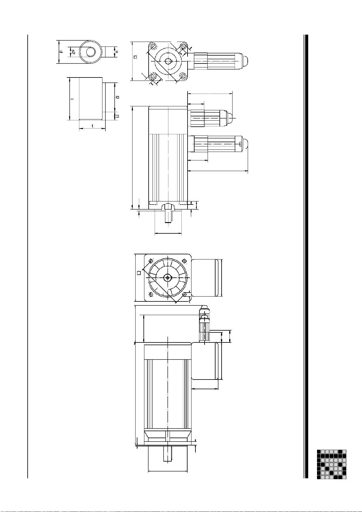
Dimensioned drawing: PMCtendo AC1
Operating Manual: PMCtendo AC 1
5,5
Msize: 2x Msize: 5x ... Ax
Dimensioned drawing
Technical Details
a1
L
Æ
10
f1
e1
11,5
b1
Æ
70
24
34
90
12
c1
a1
90
L
f1
70
Æ
e1
s1
91
34
24 84
67
c1
2 16
b1
Æ
Page 67

L [mH]
R20 [Ohm]
KT [Nm/A]
KE [Vs]
Tth [min]
Uin [V]
2p
2 - 17
nmax [min-1]
nN [min-1]
Imax [A]
IN [A]
I0 [A]
Mmax [Nm]
MN [Nm]
6000 rpm 6000 rpm 4 263 V 32 min 0,42 V 0,73 Nm 203,00 Ohm 172,00 mH
0,22 A 0,97 A
6000 rpm 6000 rpm 4 263 V 35 min 0,42 V 0,73 Nm 51,00 Ohm 71,80 mH
3000 rpm 6000 rpm 4 263 V 35 min 0,84 V 1,45 Nm 229,00 Ohm 289,00 mH
0,44 A 1,93 A
0,26 A 0,97 A
3000 rpm 6000 rpm 4 263 V 38 min 0,84 V 1,45 Nm 114,00 Ohm 173,00 mH
0,39 A 1,45 A
4000 rpm 6000 rpm 4 263 V 40 min 0,63 V 1,09 Nm 41,20 Ohm 73,60 mH
6000 rpm 6000 rpm 4 263 V 40 min 0,42 V 0,73 Nm 18,80 Ohm 32,40 mH
0,88 A 3,86 A
0,88 A 3,86 A
6000 rpm 6000 rpm 4 263 V 32 min 0,42 V 0,73 Nm 23,00 Ohm 55,60 mH
3000 rpm 6000 rpm 4 263 V 32 min 0,84 V 1,45 Nm 91,80 Ohm 222,20 mH
0,97 A 2,83 A
0,55 A 1,41 A
4000 rpm 6000 rpm 4 263 V 35 min 0,63 V 1,09 Nm 17,20 Ohm 62,50 mH
6000 rpm 6000 rpm 4 263 V 35 min 0,42 V 0,73 Nm 7,70 Ohm 27,80 mH
1,30 A 3,80 A
1,93 A 5,60 A
4000 rpm 6000 rpm 4 263 V 35 min 0,63 V 1,09 Nm 17,20 Ohm 62,50 mH
3000 rpm 6000 rpm 4 263 V 35 min 0,84 V 1,45 Nm 30,60 Ohm 111,10 mH
1,30 A 3,80 A
1,10 A 2,83 A
4000 rpm 6000 rpm 4 263 V 38 min 0,63 V 1,09 Nm 9,90 Ohm 41,70 mH
6000 rpm 6000 rpm 4 263 V 38 min 0,42 V 0,73 Nm 4,40 Ohm 18,50 mH
1,80 A 5,40 A
2,70 A 8,10 A
3000 rpm 6000 rpm 4 263 V 38 min 0,84 V 1,45 Nm 17,60 Ohm 74,10 mH
3000 rpm 6000 rpm 8 268 V 35 min 0,85 V 1,48 Nm 13,50 Ohm 22,80 mH
1,55 A 4,10 A
1,08 A 4,81 A
3000 rpm 9000 rpm 8 296 V 38 min 0,94 V 1,63 Nm 9,70 Ohm 18,30 mH
2000 rpm 6000 rpm 8 268 V 40 min 1,28 V 2,22 Nm 10,40 Ohm 20,60 mH
1,60 A 6,13 A
2,05 A 8,12 A
M0 [Nm]
UN [V]
Performance data: PMCtendo AC2
Msize
Technical Details
Performance data
21 400 V 0,20 Nm 0,16 Nm 0,70 Nm 0,28 A
22 400 V 0,40 Nm 0,32 Nm 1,40 Nm 0,55 A
22 400 V 0,40 Nm 0,38 Nm 1,40 Nm 0,28 A
23 400 V 0,60 Nm 0,57 Nm 2,10 Nm 0,41 A
24 400 V 0,80 Nm 0,64 Nm 2,80 Nm 1,10 A
24 400 V 0,80 Nm 0,64 Nm 2,80 Nm 1,10 A
31 400 V 0,82 Nm 0,70 Nm 2,10 Nm 1,13 A
31 400 V 0,82 Nm 0,80 Nm 2,10 Nm 0,57 A
32 400 V 1,64 Nm 1,40 Nm 4,10 Nm 1,50 A
32 400 V 1,64 Nm 1,40 Nm 4,10 Nm 2,20 A
32 400 V 1,64 Nm 1,50 Nm 4,10 Nm 1,50 A
32 400 V 1,64 Nm 1,60 Nm 4,10 Nm 1,13 A
33 400 V 2,35 Nm 2,00 Nm 5,90 Nm 2,20 A
33 400 V 2,35 Nm 2,00 Nm 5,90 Nm 3,20 A
33 400 V 2,35 Nm 2,25 Nm 5,90 Nm 1,62 A
52 400 V 2,00 Nm 1,60 Nm 7,10 Nm 1,35 A
53 400 V 3,20 Nm 2,60 Nm 10,00 Nm 1,97 A
55 400 V 5,30 Nm 4,54 Nm 18,00 Nm 2,39 A
Operating Manual: PMCtendo AC 1
Page 68

Performance data
Operating Manual: PMCtendo AC 1
73 400 V 12,00 Nm 9,00 Nm 60,00 Nm 9,80 A
74 400 V 16,00 Nm 12,00 Nm 80,00 Nm 13,10 A
73 400 V 12,00 Nm 10,50 Nm 60,00 Nm 7,40 A
72 400 V 8,00 Nm 7,00 Nm 40,00 Nm 4,90 A
65 400 V 10,00 Nm 9,00 Nm 50,00 Nm 6,10 A
65 400 V 10,00 Nm 8,00 Nm 50,00 Nm 8,20 A
64 400 V 8,00 Nm 7,20 Nm 40,00 Nm 4,90 A
64 400 V 8,00 Nm 6,40 Nm 40,00 Nm 6,50 A
63 400 V 6,00 Nm 5,40 Nm 30,00 Nm 3,70 A
63 400 V 6,00 Nm 5,10 Nm 30,00 Nm 4,90 A
63 400 V 6,00 Nm 4,80 Nm 30,00 Nm 7,40 A
63 400 V 6,00 Nm 4,80 Nm 30,00 Nm 7,40 A
63 400 V 6,00 Nm 4,80 Nm 30,00 Nm 4,90 A
62 400 V 4,00 Nm 3,60 Nm 20,00 Nm 2,50 A
62 400 V 4,00 Nm 3,50 Nm 20,00 Nm 2,50 A
62 400 V 4,00 Nm 3,40 Nm 20,00 Nm 3,30 A
62 400 V 4,00 Nm 3,40 Nm 20,00 Nm 3,30 A
62 400 V 4,00 Nm 3,20 Nm 20,00 Nm 4,90 A
Performance data: PMCtendo AC2
Msize
Technical Details
UN [V]
M0 [Nm]
MN [Nm]
Mmax [Nm]
I0 [A]
7,40 A 49,10 A
9,80 A 65,40 A
4000 rpm 4000 rpm 8 296 V 45 min 0,71 V 1,22 Nm 0,83 Ohm 4,22 mH
4000 rpm 4000 rpm 8 296 V 45 min 0,71 V 1,22 Nm 0,53 Ohm 3,91 mH
4,30 A 24,50 A
6,40 A 36,80 A
3000 rpm 4000 rpm 8 296 V 40 min 0,94 V 1,63 Nm 2,59 Ohm 13,30 mH
3000 rpm 4000 rpm 8 296 V 45 min 0,94 V 1,63 Nm 1,49 Ohm 7,65 mH
6,50 A 41,00 A
5,50 A 30,70 A
4000 rpm 6000 rpm 8 296 V 30 min 0,71 V 1,22 Nm 0,86 Ohm 4,20 mH
3000 rpm 4000 rpm 8 296 V 30 min 0,94 V 1,63 Nm 1,60 Ohm 7,70 mH
5,20 A 32,70 A
4,40 A 24,50 A
4000 rpm 6000 rpm 8 296 V 30 min 0,71 V 1,22 Nm 1,18 Ohm 5,30 mH
3000 rpm 4000 rpm 8 296 V 30 min 0,94 V 1,63 Nm 2,10 Ohm 8,70 mH
3,90 A 24,50 A
3,30 A 18,40 A
4000 rpm 4000 rpm 8 296 V 30 min 0,71 V 1,22 Nm 1,85 Ohm 7,80 mH
3000 rpm 4000 rpm 8 296 V 30 min 0,94 V 1,63 Nm 3,10 Ohm 13,20 mH
5,90 A 37,00 A
5,90 A 37,00 A
6000 rpm 4000 rpm 8 296 V 30 min 0,47 V 0,82 Nm 0,98 Ohm 3,80 mH
6000 rpm 6000 rpm 8 296 V 30 min 0,47 V 0,82 Nm 0,98 Ohm 3,80 mH
2,20 A 12,30 A
3,90 A 24,50 A
3000 rpm 4000 rpm 8 296 V 25 min 0,94 V 1,63 Nm 6,40 Ohm 21,20 mH
4000 rpm 4000 rpm 8 296 V 30 min 0,71 V 1,22 Nm 1,85 Ohm 7,80 mH
2,60 A 16,40 A
2,20 A 12,30 A
4000 rpm 6000 rpm 8 296 V 25 min 0,71 V 1,22 Nm 3,60 Ohm 11,90 mH
3000 rpm 4000 rpm 8 296 V 25 min 0,94 V 1,63 Nm 6,40 Ohm 21,20 mH
3,90 A 24,50 A
2,60 A 16,40 A
6000 rpm 6000 rpm 8 296 V 25 min 0,47 V 0,82 Nm 1,75 Ohm 5,50 mH
4000 rpm 4000 rpm 8 296 V 25 min 0,71 V 1,22 Nm 3,60 Ohm 11,90 mH
IN [A]
Imax [A]
nN [min-1]
nmax [min-1]
2p
Uin [V]
Tth [min]
KE [Vs]
KT [Nm/A]
R20 [Ohm]
L [mH]
2 - 18
Page 69

L [mH]
R20 [Ohm]
KT [Nm/A]
KE [Vs]
Tth [min]
Uin [V]
2p
2 - 19
nmax [min-1]
nN [min-1]
Imax [A]
IN [A]
I0 [A]
Mmax [Nm]
MN [Nm]
2000 rpm 4000 rpm 8 296 V 45 min 1,41 V 2,45 Nm 2,02 Ohm 14,90 mH
3000 rpm 4000 rpm 8 296 V 45 min 0,94 V 1,63 Nm 0,90 Ohm 6,60 mH
49,10 A
5,60 A 32,70 A
3000 rpm 4000 rpm 8 296 V 45 min 0,94 V 1,63 Nm 0,90 Ohm 6,60 mH
3000 rpm 4000 rpm 8 296 V 45 min 0,94 V 1,63 Nm 0,90 Ohm 6,60 mH
8,60 A 49,10 A
10,70 A 49,00 A
4000 rpm 4000 rpm 8 296 V 50 min 0,71 V 1,22 Nm 0,39 Ohm 3,03 mH
6000 rpm 4000 rpm 8 296 V 50 min 0,47 V 0,82 Nm 0,24 Ohm 2,09 mH
12,30 A 81,80 A
18,40 A 123,00 A
3000 rpm 4000 rpm 8 296 V 50 min 0,94 V 1,63 Nm 0,68 Ohm 5,22 mH
3000 rpm 4000 rpm 8 296 V 50 min 0,94 V 1,63 Nm 0,68 Ohm 5,22 mH
10,70 A 61,30 A
10,70 A 61,50 A
4000 rpm 4000 rpm 8 296 V 50 min 0,71 V 1,22 Nm 0,45 Ohm 3,92 mH
3000 rpm 4000 rpm 8 296 V 50 min 0,94 V 1,63 Nm 0,49 Ohm 3,75 mH
16,40 A 86,00 A
12,90 A 74,00 A
2000 rpm 4000 rpm 8 296 V 50 min 1,41 V 2,45 Nm 1,14 Ohm 8,77 mH
3000 rpm 4000 rpm 8 296 V 55 min 0,94 V 1,63 Nm 0,74 Ohm 5,30 mH
8,60 A 49,10 A
15,10 A 66,20 A
3000 rpm 4000 rpm 8 296 V 55 min 0,94 V 1,63 Nm 0,67 Ohm 5,97 mH
15,00 A 85,90 A
M0 [Nm]
UN [V]
Performance data: PMCtendo AC2
Msize
Technical Details
Performance data
74 400 V 16,00 Nm 14,00 Nm 80,00 Nm 6,50 A
74 400 V 16,00 Nm 14,00 Nm 80,00 Nm 9,80 A
74 400 V 16,00 Nm 14,00 Nm 80,00 Nm 9,80 A
74 400 V 16,00 Nm 14,00 Nm 80,00 Nm 9,80 A
75 400 V 20,00 Nm 15,00 Nm 100,00 Nm 16,40 A
75 400 V 20,00 Nm 15,00 Nm 100,00 Nm 24,50 A
75 400 V 20,00 Nm 17,50 Nm 100,00 Nm 12,30 A
75 400 V 20,00 Nm 17,50 Nm 100,00 Nm 12,30 A
76 400 V 24,00 Nm 19,50 Nm 120,00 Nm 19,50 A
76 400 V 24,00 Nm 21,00 Nm 120,00 Nm 14,70 A
76 400 V 24,00 Nm 21,00 Nm 120,00 Nm 9,80 A
77 400 V 27,30 Nm 24,60 Nm 108,00 Nm 16,70 A
77 400 V 28,00 Nm 24,50 Nm 140,00 Nm 17,20 A
Operating Manual: PMCtendo AC 1
Page 70

Operating Manual: PMCtendo AC 1
32 yes
32 yes
31
31
31
31 yes
24
24 yes
24
23
22
22 yes
22
21
21
Msize
Mechanical data: PMCtendo AC2
Mechanical data
Technical Details
BR
no 0,10 kgcm² 118 mm Resolver 2-pole 1.500 g no
no 0,62 kgcm² 172 mm Resolver 2-pole 2.800 g no
no 0,62 kgcm² 207 mm Hiperface multi-turn 2.800 g no
no 0,62 kgcm² 207 mm Hiperface single-turn 2.800 g no
no 0,26 kgcm² 195 mm Hiperface multi-turn 2.100 g no
no 0,26 kgcm² 163 mm Resolver 2-pole 2.100 g no
no 0,21 kgcm² 148 mm Resolver 2-pole 1.900 g no
no 0,16 kgcm² 133 mm Resolver 2-pole 1.700 g no
no 0,16 kgcm² 165 mm Hiperface multi-turn 1.700 g no
no 0,10 kgcm² 150 mm Hiperface single-turn 1.500 g no
24VDC/0,51A/3,5Nm 1,14 kgcm² 239 mm Resolver 2-pole 3.300 g no
24VDC/0,51A/3,5Nm 1,14 kgcm² 274 mm Hiperface multi-turn 3.300 g no
24VDC/0,51A/3,5Nm 1,00 kgcm² 199 mm Resolver 2-pole 3.400 g no
0,32 kgcm² 191 mm Resolver 2-pole 2.400 g no
24VDC/0,35A/1,2Nm 0,23 kgcm² 161 mm Resolver 2-pole 1.850 g no
BrValues
J [ kgcm²]
L [mm]
2 20
MFB
mNet
Fan
Page 71

Fan
mNet
MFB
21
2 -
L [mm]
J [ kgcm²]
BrValues
24VDC/0,51A/3,5Nm 1,52 kgcm² 239 mm Resolver 2-pole 3.300 g no
24VDC/0,51A/3,5Nm 1,52 kgcm² 274 mm Hiperface single-turn 3.300 g no
no 1,14 kgcm² 212 mm Resolver 2-pole 4.000 g no
no 1,14 kgcm² 247 mm Hiperface single-turn 4.000 g no
no 1,14 kgcm² 247 mm Hiperface multi-turn 4.000 g no
24VDC/0,51A/3,5Nm 2,04 kgcm² 279 mm Resolver 2-pole 5.700 g no
24VDC/0,51A/3,5Nm 2,04 kgcm² 314 mm Hiperface multi-turn 5.700 g no
24VDC/0,51A/3,5Nm 2,04 kgcm² 314 mm Hiperface single-turn 5.700 g no
no 1,66 kgcm² 253 mm Resolver 2-pole 5.100 g no
no 1,66 kgcm² 287 mm Hiperface multi-turn 5.100 g no
2,22 kgcm² 236 mm Resolver 2-pole 6.000 g no
no 1,66 kgcm² 287 mm Hiperface single-turn 5.100 g no
no 1,40 kgcm² 289 mm Ext. encoder mount-ready 4.400 g no
no 1,84 kgcm² 236 mm Resolver 2-pole 5.400 g no
no 2,72 kgcm² 285 mm Hiperface multi-turn 7.400 g no
BR
Msize
Technical Details
Mechanical data: PMCtendo AC2
Mechanical data
32 yes
32 yes
32
32
32
33 yes
33 yes
33 yes
33
33
33
52
53 yes
53
55
Operating Manual: PMCtendo AC 1
Page 72

Operating Manual: PMCtendo AC 1
64
64 yes
64 yes
64 yes
63
63
63
63 yes
63 yes
63 yes
62
62
62
62 yes
62 yes
Msize
Mechanical data
Mechanical data: PMCtendo AC2
Technical Details
BR
no 6,20 kgcm² 224 mm Resolver 2-pole 7.100 g no
no 6,20 kgcm² 256 mm Hiperface multi-turn 7.100 g no
no 10,00 kgcm² 274 mm Resolver 2-pole 10.100 g no
no 8,01 kgcm² 281 mm Hiperface single-turn 9.000 g no
no 8,01 kgcm² 249 mm Resolver 2-pole 9.000 g no
no 8,01 kgcm² 281 mm Hiperface multi-turn 9.000 g no
no 6,20 kgcm² 256 mm Hiperface single-turn 7.100 g no
24VDC/0,71A/9,5Nm 13,60 kgcm² 337 mm Hiperface multi-turn 12.000 g no
24VDC/0,71A/9,5Nm 13,60 kgcm² 337 mm Hiperface single-turn 12.000 g no
24VDC/0,71A/9,5Nm 13,60 kgcm² 305 mm Resolver 2-pole 12.000 g no
24VDC/0,71A/9,5Nm 11,61 kgcm² 312 mm Hiperface multi-turn 10.100 g no
24VDC/0,71A/9,5Nm 11,61 kgcm² 312 mm Hiperface single-turn 10.100 g no
24VDC/0,71A/9,5Nm 11,61 kgcm² 280 mm Resolver 2-pole 10.100 g no
24VDC/0,71A/9,5Nm 9,80 kgcm² 287 mm Hiperface multi-turn 10.100 g no
24VDC/0,71A/9,5Nm 9,80 kgcm² 255 mm Resolver 2-pole 10.100 g no
BrValues
J [ kgcm²]
L [mm]
2 22
MFB
mNet
Fan
Page 73

Fan
mNet
MFB
23
2 -
L [mm]
J [ kgcm²]
BrValues
24VDC/0,71A/9,5Nm 15,50 kgcm² 330 mm Resolver 2-pole 13.900 g no
no 10,00 kgcm² 306 mm Hiperface multi-turn 10.100 g no64 no 10,00 kgcm² 306 mm Hiperface single-turn 10.100 g no
24VDC/0,71A/9,5Nm 15,50 kgcm² 362 mm Resolver 2-pole 13.900 g no
24VDC/0,71A/9,5Nm 15,50 kgcm² 362 mm Hiperface multi-turn 13.900 g no
no 11,90 kgcm² 299 mm Resolver 2-pole 12.000 g no
24VDC/0,96A/27,0Nm 26,90 kgcm² 289 mm Hiperface multi-turn 16.000 g no
24VDC/0,96A/27,0Nm 26,90 kgcm² 289 mm Resolver 2-pole 16.000 g no
no 11,90 kgcm² 331 mm Hiperface single-turn 12.000 g no
no 12,70 kgcm² 234 mm Hiperface multi-turn 12.000 g no
no 12,70 kgcm² 234 mm Resolver 2-pole 12.000 g no
24VDC/0,96A/27,0Nm 31,60 kgcm² 314 mm Resolver 2-pole 18.300 g no
24VDC/0,96A/27,0Nm 26,90 kgcm² 311 mm Hiperface multi-turn 16.000 g no
no 17,40 kgcm² 259 mm Resolver 2-pole 14.100 g no
24VDC/0,96A/27,0Nm 31,60 kgcm² 336 mm Hiperface multi-turn 18.300 g no
BR
Msize
Technical Details
Mechanical data: PMCtendo AC2
Mechanical data
64
65 yes
65 yes
65 yes
65
65
72
72
73 yes
73 yes
73 yes
73
74 yes
74 yes
Operating Manual: PMCtendo AC 1
Page 74
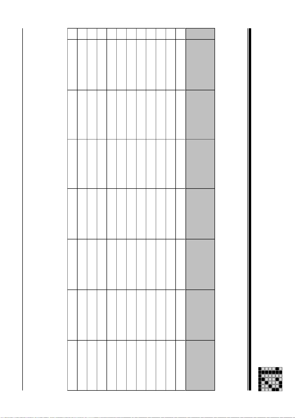
Operating Manual: PMCtendo AC 1
77
77
76
76
76
75
75
75 yes
74
75 yes
74
74
Msize
Mechanical data
Mechanical data: PMCtendo AC2
Technical Details
BR
no 31,50 kgcm² 334 mm Resolver 2-pole 20.300 g no
no 31,50 kgcm² 334 mm Resolver 2-pole 20.800 g no
no 31,50 kgcm² 356 mm Hiperface single-turn 20.800 g no
no 36,20 kgcm² 359 mm Hiperface multi-turn 23.000 g no
no 52,26 kgcm² 472 mm Hiperface multi-turn 25.800 g yes
no 26,80 kgcm² 309 mm Hiperface mult-iturn 18.600 g no
no 26,80 kgcm² 309 mm Hiperface single-turn 18.600 g no
24VDC/0,96A/27,0Nm 36,30 kgcm² 361 mm Hiperface multi-turn 20.500 g no
no 22,10 kgcm² 284 mm Resolver 2-pole 16.400 g no
24VDC/0,96A/27,0Nm 36,30 kgcm² 339 mm Resolver 2-pole 20.500 g no
no 22,10 kgcm² 284 mm Hiperface multi-turn 16.400 g no
no 22,10 kgcm² 284 mm Hiperface single-turn 16.400 g no
BrValues
J [ kgcm²]
L [mm]
MFB
mNet
2 24
Fan
Page 75

u [mm]
t [mm]
s2 [mm]
s1 [mm]
l2 [mm]
l1 [mm]
2 - 25
l [mm]
f1 [mm]
e1 [mm]
d [mm]
c1 [mm]
b1 [mm]
a2 [mm]
a1 [mm]
Technical Details
Dimensions
Msize
Dimensions: PMCtendo AC2
21 9 mm58 mm 40 mm 8 mm 63 mm 2,5 mm 20 mm 2,5 mm 15 mm 5,5 mm 10,5 mm 3 mm
22 9 mm58 mm 40 mm 8 mm 63 mm 2,5 mm 20 mm 2,5 mm 15 mm 5,5 mm 10,5 mm 3 mm
23 9 mm58 mm 40 mm 8 mm 63 mm 2,5 mm 20 mm 2,5 mm 15 mm 5,5 mm 10,5 mm 3 mm
24 9 mm58 mm 40 mm 8 mm 63 mm 2,5 mm 20 mm 2,5 mm 15 mm 5,5 mm 10,5 mm 3 mm
31 11 mm70 mm 77 mm 60 mm 6 mm 75 mm 2,5 mm 23 mm 4,0 mm 14 mm 5,8 mm M4 x 9 12,5 mm 4 mm
32 11 mm70 mm 77 mm 60 mm 6 mm 75 mm 2,5 mm 23 mm 4,0 mm 14 mm 5,8 mm M4 x 9 12,5 mm 4 mm
33 11 mm70 mm 77 mm 60 mm 6 mm 75 mm 2,5 mm 23 mm 4,0 mm 14 mm 5,8 mm M4 x 9 12,5 mm 4 mm
52 14 mm92 mm 80 mm 11 mm 100 mm 3,0 mm 30 mm 5,0 mm 20 mm 6,6 mm M5 x 10 16,0 mm 5 mm
53 14 mm92 mm 80 mm 11 mm 100 mm 3,0 mm 30 mm 5,0 mm 20 mm 6,6 mm M5 x 10 16,0 mm 5 mm
55 14 mm92 mm 80 mm 11 mm 100 mm 3,0 mm 30 mm 5,0 mm 20 mm 6,6 mm M5 x 10 16,0 mm 5 mm
62 19 mm115 mm 95 mm 8 mm 115 mm 3,0 mm 40 mm 5,0 mm 30 mm 9,0 mm M6 x 20 21,0 mm 6 mm
63 19 mm115 mm 95 mm 8 mm 115 mm 3,0 mm 40 mm 5,0 mm 30 mm 9,0 mm M6 x 20 21,0 mm 6 mm
64 19 mm115 mm 95 mm 8 mm 115 mm 3,0 mm 40 mm 5,0 mm 30 mm 9,0 mm M6 x 20 21,0 mm 6 mm
65 19 mm115 mm 95 mm 8 mm 115 mm 3,0 mm 40 mm 5,0 mm 30 mm 9,0 mm M6 x 20 21,0 mm 6 mm
72 24 mm142 mm 130 mm 12 mm 165 mm 3,5 mm 50 mm 5,0 mm 40 mm 12,0 mm M8 x 20 27,0 mm 8 mm
Operating Manual: PMCtendo AC 1
Page 76
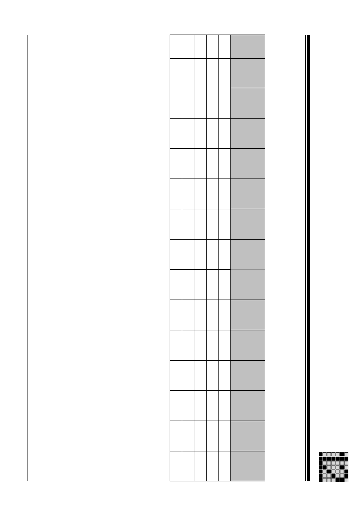
Dimensions
Operating Manual: PMCtendo AC 1
74 24 mm142 mm 130 mm 12 mm 165 mm 3,5 mm 50 mm 5,0 mm 40 mm 12,0 mm M8 x 20 27,0 mm 8 mm
75 24 mm142 mm 130 mm 12 mm 165 mm 3,5 mm 50 mm 5,0 mm 40 mm 12,0 mm M8 x 20 27,0 mm 8 mm
76 24 mm142 mm 130 mm 12 mm 165 mm 3,5 mm 50 mm 5,0 mm 40 mm 12,0 mm M8 x 20 27,0 mm 8 mm
77 24 mm142 mm 130 mm 12 mm 165 mm 3,5 mm 50 mm 5,0 mm 40 mm 12,0 mm M8 x 20 27,0 mm 8 mm
73 24 mm142 mm 130 mm 12 mm 165 mm 3,5 mm 50 mm 5,0 mm 40 mm 12,0 mm M8 x 20 27,0 mm 8 mm
Dimensions: PMCtendo AC2
Msize
a1 [mm]
a2 [mm]
b1 [mm]
c1 [mm]
d [mm]
Technical Details
e1 [mm]
f1 [mm]
l [mm]
l1 [mm]
l2 [mm]
s1 [mm]
s2 [mm]
t [mm]
u [mm]
2 - 26
Page 77
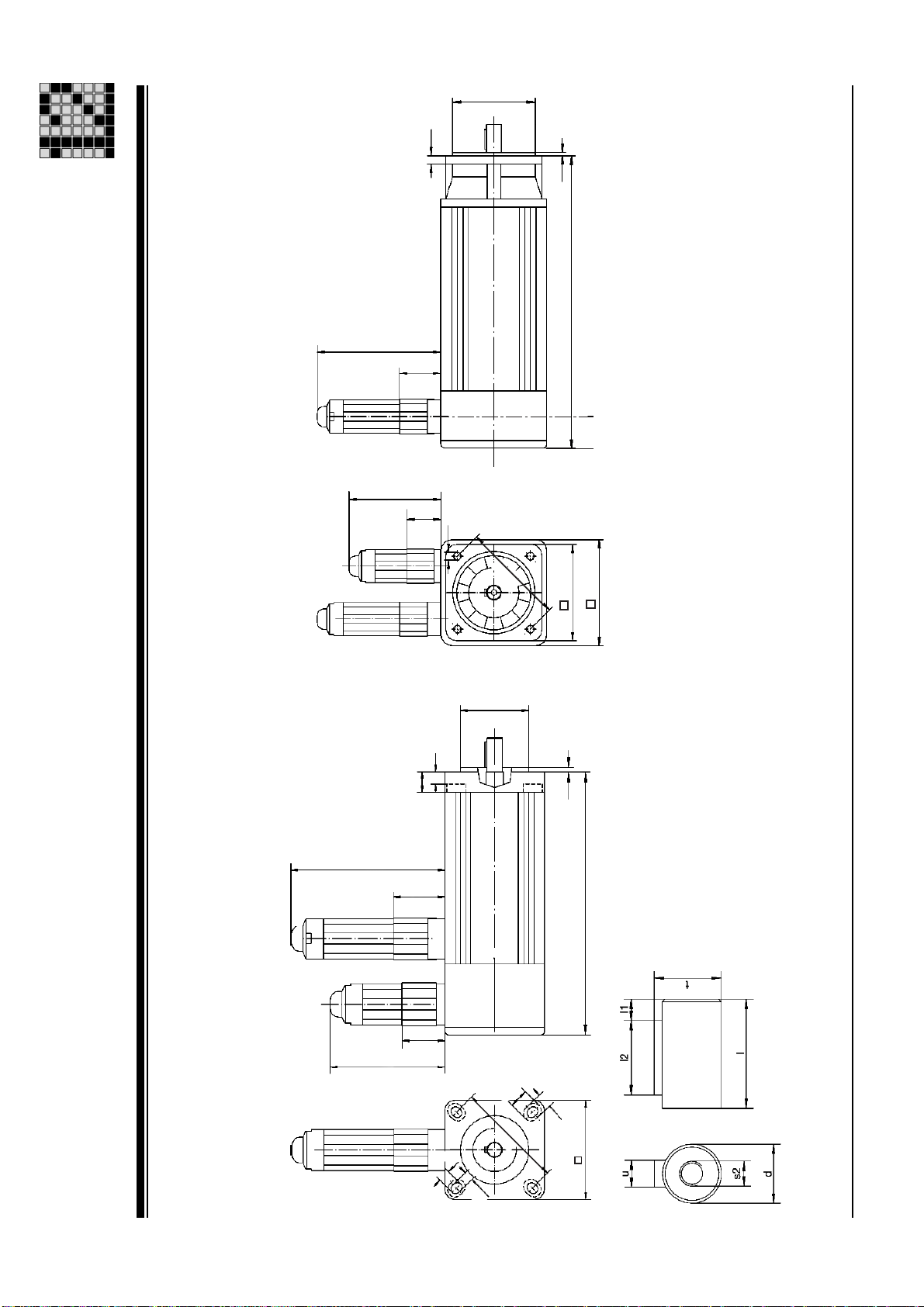
90
70
c1
34
24
s1
b1
Æ
27
2 -
f1
L
36
90
12
34
c1
b1
e1
Æ
Æ
f1
a1
a2
Beachten:
zusätzliche Länge
bei Hiperface Drehgeber:
L
Technical Details
Dimensioned drawing: PMCtendo AC2
Dimensioned drawing
Msize: 2x Msize: 3x
70
24
5,5
11,5
e1
Æ
10
a1
Operating Manual: PMCtendo AC 1
Page 78
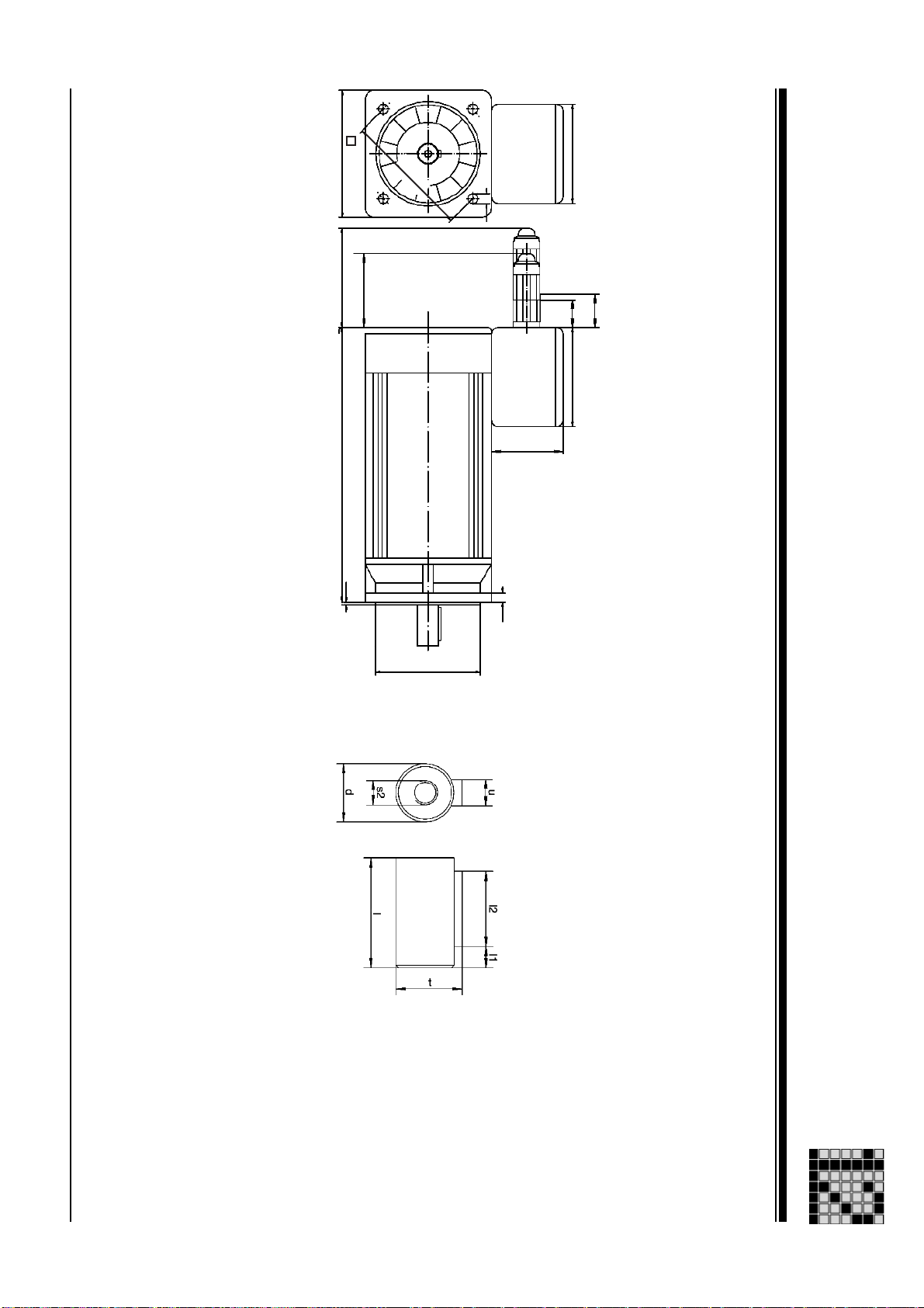
Operating Manual: PMCtendo AC 1
Msize: 5x ... 7x
Dimensioned drawing
Dimensioned drawing: PMCtendo AC2
Technical Details
a1
90
L
f1
70
Æ
e1
s1
91
34
24 84
67
c1
b1
Æ
2 28
Page 79

L [mH]
R20 [Ohm]
KT [Nm/A]
KE [Vs]
Tth [min]
Uin [V]
2p
2 - 29
nmax [min-1]
nN [min-1]
Imax [A]
IN [A]
I0 [A]
Mmax [Nm]
MN [Nm]
6000 rpm 6000 rpm 4 264 V 32 min 0,42 V 0,73 Nm 25,10 Ohm 48,60 mH
3000 rpm 6000 rpm 4 264 V 32 min 0,84 V 1,45 Nm 97,50 Ohm 82,30 mH
0,69 A 2,89 A
0,38 A 1,44 A
6000 rpm 6000 rpm 4 264 V 35 min 0,42 V 0,73 Nm 8,10 Ohm 20,60 mH
4000 rpm 6000 rpm 4 264 V 35 min 0,84 V 1,09 Nm 32,20 Ohm 82,30 mH
1,37 A 5,77 A
0,76 A 3,85 A
3000 rpm 6000 rpm 4 264 V 35 min 0,84 V 1,45 Nm 32,20 Ohm 82,30 mH
3000 rpm 6000 rpm 4 264 V 38 min 0,84 V 1,45 Nm 17,60 Ohm 53,70 mH
0,76 A 2,89 A
1,13 A 4,33 A
6000 rpm 6000 rpm 4 264 V 40 min 0,42 V 0,73 Nm 3,30 Ohm 10,50 mH
4000 rpm 6000 rpm 4 264 V 40 min 0,63 V 1,09 Nm 7,40 Ohm 24,20 mH
2,75 A 12,03 A
1,92 A 8,02 A
3000 rpm 6000 rpm 4 264 V 40 min 0,84 V 1,45 Nm 13,60 Ohm 42,80 mH
4000 rpm 6000 rpm 4 264 V 43 min 0,63 V 1,09 Nm 5,10 Ohm 15,80 mH
1,51 A 6,01 A
2,38 A 9,62 A
3000 rpm 6000 rpm 4 264 V 43 min 0,84 V 1,45 Nm 8,80 Ohm 28,10 mH
3000 rpm 6000 rpm 8 296 V 35 min 0,94 V 1,63 Nm 1,60 Ohm 14,00 mH
1,89 A 7,22 A
5,80 A 28,19 A
3000 rpm 6000 rpm 8 296 V 38 min 0,94 V 1,63 Nm 1,17 Ohm 10,50 mH
2000 rpm 6000 rpm 8 296 V 38 min 1,41 V 2,45 Nm 2,90 Ohm 32,20 mH
7,90 A 38,00 A
5,30 A 25,30 A
4000 rpm 6000 rpm 8 296 V 40 min 0,71 V 1,22 Nm 0,40 Ohm 4,40 mH
13,80 A 76,80 A
M0 [Nm]
UN [V]
Performance data: PMCtendo AC3
Msize
Technical Details
Performance data
31 400 V 0,60 Nm 0,50 Nm 2,10 Nm 0,82 A
31 400 V 0,60 Nm 0,55 Nm 2,10 Nm 0,41 A
32 400 V 1,20 Nm 1,00 Nm 4,20 Nm 1,65 A
32 400 V 1,20 Nm 1,06 Nm 4,20 Nm 1,10 A
32 400 V 1,20 Nm 1,10 Nm 4,20 Nm 0,82 A
33 400 V 1,80 Nm 1,65 Nm 6,30 Nm 1,24 A
34 400 V 2,50 Nm 2,00 Nm 8,75 Nm 3,44 A
34 400 V 2,50 Nm 2,10 Nm 8,75 Nm 2,29 A
34 400 V 2,50 Nm 2,20 Nm 8,75 Nm 1,72 A
35 400 V 3,00 Nm 2,60 Nm 10,50 Nm 2,75 A
35 400 V 3,00 Nm 2,75 Nm 10,50 Nm 2,06 A
73 400 V 11,00 Nm 9,50 Nm 46,00 Nm 6,80 A
74 400 V 15,00 Nm 12,80 Nm 62,00 Nm 9,20 A
74 400 V 15,00 Nm 12,86 Nm 62,00 Nm 6,10 A
76 400 V 23,00 Nm 16,89 Nm 94,00 Nm 18,79 A
Operating Manual: PMCtendo AC 1
Page 80

Operating Manual: PMCtendo AC 1
35 yes
34
34
34
34 yes
33
32
32
32
32 yes
32 yes
31
31
31
31 yes
Msize
Mechanical data: PMCtendo AC3
Mechanical data
Technical Details
BR
no 0,42 kgcm² 126 mm Resolver 2-pole 1.400 g no
no 0,42 kgcm² 172 mm Hiperface multi-turn 1.400 g no
no 1,42 kgcm² 201 mm Resolver 2-pole 4.000 g no
no 1,42 kgcm² 247 mm Hiperface multi-turn 4.000 g no
no 1,42 kgcm² 247 mm Hiperface single-turn 4.000 g no
no 1,10 kgcm² 222 mm Hiperface multi-turn 3.100 g no
no 0,77 kgcm² 151 mm Resolver 2-pole 2.200 g no
no 0,77 kgcm² 197 mm Hiperface multi-turn 2.200 g no
no 0,77 kgcm² 197 mm Hiperface single-turn 2.200 g no
no 0,42 kgcm² 172 mm Hiperface single-turn 1.400 g no
24VDC/0,45A/3,2Nm 2,12 kgcm² 273 mm Resolver 2-pole 5.500 g no
24VDC/0,45A/3,2Nm 1,80 kgcm² 248 mm Resolver 2-pole 4.600 g no
24VDC/0,45A/3,2Nm 1,15 kgcm² 198 mm Resolver 2-pole 2.800 g no
24VDC/0,45A/3,2Nm 1,15 kgcm² 244 mm Hiperface multi-turn 2.800 g no
24VDC/0,45A/3,2Nm 0,80 kgcm² 219 mm Hiperface multi-turn 2.000 g no
BrValues
J [ kgcm²]
L [mm]
2 30
MFB
mNet
Fan
Page 81

Fan
mNet
MFB
31
2 -
L [mm]
J [ kgcm²]
BrValues
no 1,74 kgcm² 226 mm Resolver 2-pole 4.900 g no
no 1,74 kgcm² 272 mm H iperface multi-turn 4.900 g no
no 8,10 kgcm² 259 mm Hiperface multi-turn 14.100 g no
no 10,00 kgcm² 284 mm Hiperface single-turn 16.400 g no
no 10,00 kgcm² 284 mm Resolver 2-pole 16.400 g no
24VDC/0,96A/27,0Nm 23,30 kgcm² 334 mm Hiperface multi-turn 22.700 g no
BR
Msize
Technical Details
Mechanical data: PMCtendo AC3
Mechanical data
35
35
73
74
74
76 yes
Operating Manual: PMCtendo AC 1
Page 82

Dimensions
Operating Manual: PMCtendo AC 1
32 11 mm70 mm 77 mm 60 mm 6 mm 75 mm 2,5 mm 23 mm 4,0 mm 14 mm 5,8 mm M4 x 9 12,5 mm 4 mm
33 11 mm70 mm 77 mm 60 mm 6 mm 75 mm 2,5 mm 23 mm 4,0 mm 14 mm 5,8 mm M4 x 9 12,5 mm 4 mm
34 11 mm70 mm 77 mm 60 mm 6 mm 75 mm 2,5 mm 23 mm 4,0 mm 14 mm 5,8 mm M4 x 9 12,5 mm 4 mm
35 11 mm70 mm 77 mm 60 mm 6 mm 75 mm 2,5 mm 23 mm 4,0 mm 14 mm 5,8 mm M4 x 9 12,5 mm 4 mm
73 24 mm142 mm 130 mm 12 mm 165 mm 3,5 mm 50 mm 5,0 mm 40 mm 12,0 mm M8 x 20 27,0 mm 8 mm
74 24 mm142 mm 130 mm 12 mm 165 mm 3,5 mm 50 mm 5,0 mm 40 mm 12,0 mm M8 x 20 27,0 mm 8 mm
76 24 mm142 mm 130 mm 12 mm 165 mm 3,5 mm 50 mm 5,0 mm 40 mm 12,0 mm M8 x 20 27,0 mm 8 mm
31 11 mm70 mm 77 mm 60 mm 6 mm 75 mm 2,5 mm 23 mm 4,0 mm 14 mm 5,8 mm M4 x 9 12,5 mm 4 mm
Dimensions: PMCtendo AC3
Msize
a1 [mm]
a2 [mm]
b1 [mm]
c1 [mm]
d [mm]
Technical Details
e1 [mm]
f1 [mm]
l [mm]
l1 [mm]
l2 [mm]
s1 [mm]
s2 [mm]
t [mm]
u [mm]
2 - 32
Page 83

90
70
c1
34
24
s1
b1
Æ
33
2 -
f1
L
36
34
24 84
67
c1
b1
e1
Æ
Æ
70
f1
L
90
a1
a2
Beachten:
zusätzliche Länge
bei Hiperface Drehgeber:
Technical Details
Dimensioned drawing: PMCtendo AC3
Dimensioned drawing
Msize: 7x Msize: 3x
91
s1
e1
Æ
a1
Operating Manual: PMCtendo AC 1
Page 84

Performance data
Operating Manual: PMCtendo AC 1
75 400 V 20,00 Nm 7,50 Nm 18,50 Nm 8,20 A
65 400 V 10,00 Nm 8,75 Nm 30,00 Nm 6,10 A
65 400 V 10,00 Nm 7,50 Nm 25,00 Nm 6,10 A
63 400 V 6,00 Nm 4,50 Nm 20,00 Nm 3,70 A
62 400 V 4,00 Nm 3,50 Nm 12,00 Nm 2,50 A
62 400 V 4,00 Nm 3,00 Nm 10,00 Nm 2,50 A
Performance data: PMCtendo AC4
Msize
Technical Details
UN [V]
M0 [Nm]
MN [Nm]
Mmax [Nm]
I0 [A]
5,40 A 18,40 A
7,60 A 28,30 A
3000 rpm 9000 rpm 8 296 V 35 min 0,94 V 1,63 Nm 1,96 Ohm 13,20 mH
2000 rpm 9000 rpm 8 296 V 40 min 1,41 V 2,44 Nm 1,34 Ohm 17,40 mH
2,80 A 9,20 A
4,60 A 15,30 A
3000 rpm 9000 rpm 10 296 V 30 min 0,94 V 1,63 Nm 3,45 Ohm 24,00 mH
3000 rpm 9000 rpm 10 296 V 35 min 0,94 V 1,63 Nm 1,90 Ohm 17,40 mH
1,80 A 6,10 A
2,10 A 7,40 A
3000 rpm 9000 rpm 10 296 V 25 min 0,94 V 1,63 Nm 5,43 Ohm 36,50 mH
3000 rpm 9000 rpm 8 296 V 25 min 0,94 V 1,63 Nm 4,80 Ohm 33,00 mH
IN [A]
Imax [A]
nN [min-1]
nmax [min-1]
2p
Uin [V]
Tth [min]
KE [Vs]
KT [Nm/A]
R20 [Ohm]
L [mH]
2 - 34
Page 85
Fan
mNet
MFB
35
2 -
L [mm]
J [ kgcm²]
BrValues
no 1,75 kgcm² 160 mm Resolver 2-pole 4.500 g no62 no 1,87 kgcm² 160 mm Resolver 4-pole 4.500 g no63 no 2,51 kgcm² 215 mm Hiperface single-turn 5.500 g no65 no 4,07 kgcm² 259 mm Hiperface single-turn 7.500 g no65 no 4,27 kgcm² 224 mm Resolver 4-pole 7.500 g no75 no 13,10 kgcm² 248 mm Hiperface single-turn 17.200 g no
BR
Msize
Technical Details
Mechanical data: PMCtendo AC4
Mechanical data
62
Operating Manual: PMCtendo AC 1
Page 86

Dimensions
Operating Manual: PMCtendo AC 1
63 19 mm100 mm 95 mm 18 mm 115 mm 3,0 mm 40 mm 5,0 mm 30 mm 9,0 mm M6 x 16 21,5 mm 6 mm
65 19 mm100 mm 95 mm 18 mm 115 mm 3,0 mm 40 mm 5,0 mm 30 mm 9,0 mm M6 x 16 21,5 mm 6 mm
75 24 mm142 mm 130 mm 12 mm 165 mm 3,5 mm 50 mm 5,0 mm 40 mm 12,0 mm M8 x 20 27,0 mm 8 mm
62 19 mm100 mm 95 mm 18 mm 115 mm 3,0 mm 40 mm 5,0 mm 30 mm 9,0 mm M6 x 16 21,5 mm 6 mm
Dimensions: PMCtendo AC4
Msize
a1 [mm]
a2 [mm]
b1 [mm]
c1 [mm]
d [mm]
Technical Details
e1 [mm]
f1 [mm]
l [mm]
l1 [mm]
l2 [mm]
s1 [mm]
s2 [mm]
t [mm]
u [mm]
2 - 36
Page 87

37
2 -
f1
Æ
b1
L
35
a1
e1
Æ
Technical Details
Dimensioned drawing: PMCtendo AC4
Dimensioned drawing
Msize: 6x
9
a1
Beachten:
zusätzliche Länge
bei Hiperface Drehgeber:
Operating Manual: PMCtendo AC 1
Page 88

...
In many countries we are
represented by our subsidiaries
and sales partners.
Please refer to our Homepage
for further details or contact our
headquarters.
Pilz GmbH & Co. KG
Sichere Automation
Felix-Wankel-Straße 2
73760 Ostfildern, Germany
Telephone: +49 711 3409-0
Telefax: +49 711 3409-133
E-Mail: pilz.gmbh@pilz.de
www
www.pilz.com
Technical support
+49 711 3409-444
21 894-02, 2008-01 Printed in Germany
 Loading...