

Page 1

WORKSHOP MANUAL
633234
X9 Evolution 500
Page 2

WORKSHOP
MANUAL
X9 Evolution 500
The descriptions and illustrations given in this publication are not binding. While the basic specifications
as described and illustrated in this manual remain unchanged, PIAGGIO-GILERA reserves the right, at
any time and without being required to update this publication beforehand, to make any changes to
components, parts or accessories, which it considers necessary to improve the product or which are
required for manufacturing or construction reasons.
Not all versions shown in this publication are available in all countries. The availability of single versions
should be checked at the official Piaggio sales network.
"© Copyright 2005 - PIAGGIO & C. S.p.A. Pontedera. All rights reserved. Reproduction of this publication
in whole or in part is prohibited."
PIAGGIO & C. S.p.A. - Q.C.S./After sales V.le Rinaldo Piaggio, 23 - 56025 PONTEDERA (Pi)
www.piaggio.com
Page 3

WORKSHOP MANUAL
X9 Evolution 500
This workshop manual has been drawn up by Piaggio & C. Spa to be used by the workshops of PiaggioGilera dealers. This manual is addressed to Piaggio service mechanics who are supposed to have a
basic knowledge of mechanics principles and of vehicle fixing techniques and procedures. Any important
changes made to the vehicles or to specific fixing operations will be promptly reported by updates to this
manual. Nevertheless, no fixing work can be satisfactory if the necessary equipment and tools are
unavailable. It is therefore advisable to read the sections of this manual relating to specific tools, along
with the specific tool catalogue. Important information in this manual is marked as follows.
N.B. Provides key information to make the procedure easier to understand and carry out.
CAUTION Refers to specific procedures to carry out for preventing damages to the vehicle.
WARNING Refers to specific procedures to carry out to prevent injuries to the repairer.
Personal safety Failure to completely observe these instructions will result in serious risk of personal
injury.
Safeguarding the environment Sections marked with this symbol indicate the correct use of the vehicle
to prevent damaging the environment.
Vehicle intactness The incomplete or non-observance of these regulations leads to the risk of serious
damage to the vehicle and sometimes even the invalidity of the guarantee.
Page 4

Page 5

INDEX OF TOPICS
CHARACTERISTICS CHAR
TOOLING TOOL
MAINTENANCE MAIN
TROUBLESHOOTING TROUBL
ELECTRICAL SYSTEM ELE SYS
ENGINE FROM VEHICLE ENG VE
ENGINE ENG
INJECTION INJEC
SUSPENSIONS SUSP
BRAKING SYSTEM BRAK SYS
COOLING SYSTEM COOL SYS
CHASSIS CHAS
PRE-DELIVERY PRE DE
TIME TIME
Page 6

INDEX OF TOPICS
CHARACTERISTICS CHAR
Page 7

X9 Evolution 500 Characteristics
This section describes the general specifications of the vehicle.
Rules
This section describes general safety rules for any maintenance operations performed on the vehicle.
Safety rules
•
Should it be necessary to keep the engine running while servicing, make sure that the area
or room is well ventilated, and use special exhaust fans, if required. never let the engine run
in an enclosed area. Exhaust fumes are toxic.
•
The battery electrolyte contains sulphuric acid. Protect your eyes, clothes and skin. Sulphuric acid is highly corrosive; in the event of contact with your eyes or skin, rinse thoroughly
with abundant water and seek immediate medical attention.
•
The battery produces hydrogen, a gas that can be highly explosive. Do not smoke and avoid
sparks or flames near the battery, especially when charging it.
•
Fuel is highly flammable, and in some conditions it can be explosive. Do not smoke in the
working area, and avoid open flames or sparks.
•
Clean the brake pads in a well ventilated environment, directing the compressed air jet so
as to not inhale the dust produced by the wear of the friction material. Even though the latter
contains no asbestos, dust inhalation is harmful.
Maintenance rules
•
Use original PIAGGIO spare parts and lubricants recommended by the Manufacturer. Nonoriginal or non-conforming spares may damage the vehicle.
•
Use only the special tools designed for this scooter.
•
Always use new gaskets, sealing rings and split pins upon reassembly.
•
After removal, clean the components using non-flammable or low fire-point solvent. Lubricate all the work surfaces except the tapered couplings before refitting.
•
After reassembly, check that all components have been installed properly and that they are
in good working order.
•
For removal, overhaul and reassembly operations use only tools provided with metric measures. Metric bolts, nuts and screws are not interchangeable with coupling members with
English measurement. Using unsuitable coupling members and tools may damage the
scooter.
•
Should any interventions to the scooter electrical system be required, check that the electrical connections - especially earth and battery connections - have been implemented
properly.
CHAR - 7
Page 8

Characteristics X9 Evolution 500
Vehicle identification
VEHICLE IDENTIFICATION
Specification Desc./Quantity
Chassis prefix ZAPM 27000 ÷ 4000001
Engine prefix M271M ÷ 1001
Dimensions and mass
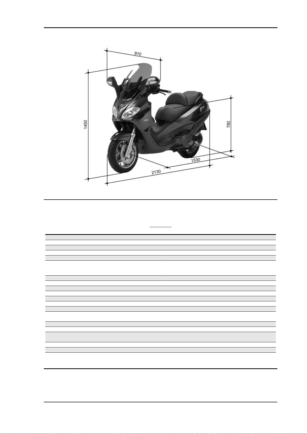
Specification
Total dry weight 206 Kg
Width (at the mirrors) 910 mm
Wheel base 2130 mm
Length 1530 mm
Height (at the saddle) 780 mm
Height at the windscreen (high position) 1450 mm
CHAR - 8
WEIGHT AND DIMENSIONS
Desc./Quantity
Page 9
X9 Evolution 500 Characteristics
Engine
CO % value (measured at the intake manifold) 1 - 1.5%
ENGINE
Specification
Engine Single-cylinder, four-stroke
Bore 92 mm
Stroke 69 mm
Cubic capacity 460 cm³
Compression ratio 10.5: 1
Timing system Single overhead camshaft with integrated tone wheel, control
from flywheel side chain, 4 valves and automatic start-up valve
Valve clearance: intake 0.15 mm (when cold)
Valve clearance: discharge 0.15 mm (when cold)
Valve clearance adjustment By threaded adjuster on the rockers
Engine idle speed 1500 ± 50 rpm
Air filter Dry paper filter.
Starting system Electric starter system with freewheel.
Lubrication By trochoidal pump (inside the crankcase), pressure adjust-
Lubrication pressure 4 bar
Minimum allowed (at 100° C) 0.8 bar
Fuel supply Electronic injection system with electric fuel pump, Ø 38 mm
Max. power (at crankshaft) 29.5 kW at 7500 rpm
Max. torque (at crankshaft) 43 Nm at 5500 rpm
Cooling system Fluid circulation through a motor-driven pump, 3-way thermo-
Desc./Quantity
lifting device.
ment by-pass and oil filter.
throttle body and single injector.
stat and electric fan.
CHAR - 9
Page 10

Characteristics X9 Evolution 500
Transmission
TRANSMISSIONS
Specification Desc./Quantity
Transmission With automatic expandable pulley variator with torque server,
V belt, automatic clutch, gear reduction unit and transmission
housing with forced air circulation cooling.
Capacities
CAPACITIES
Specification Desc./Quantity
Cooling system approx. 1.8 l
Fuel tank (including reserve ~ 2.5 l) ~ 14,5 l
Rear hub ~ 250 cc
Engine oil (empty) 1.7 lt.
Engine oil (at oil and filter change) 1.5 lt.
Electrical system
ELECTRICAL COMPONENTS
Specification
1 Ignition type Inductive, high efficiency, integrated with injection, vari-
able advance and separate HV coil.
2 Spark advance (before TDC) Variable, controlled by the injection controller
3 Spark plug CHAMPION RG6YC; NGK CR7EKB
4 Battery 12V-14Ah
5 Fuses n.1 70A_n.1 30A_n.2 15A_n.3 10A_n.4 7,5A_n.2 5A_n.
6 Generator in three-phase alternating current
Desc./Quantity
1 3A
Frame and suspensions
FRAME AND SUSPENSIONS
Specification
Type Welded structure consisting of steel pipes with asymmetrical
trestle structure, front crosspieces and union members made
Front suspension Hydraulic telescopic fork with dual effect, Ø 40 mm stems and
back pin with couplongs for dual brake calipers.
Front fork stroke 104 mm
Rear suspension Engine based on oscillating fork pivoted to the chassis by 2-
freedom degree oscillating arm and pair of dual effect hydraulic
shock absorbers with 4-position preload adjustment
Rear suspension range 76.6 mm (minimum spring preload)
Desc./Quantity
of sheet steel.
X9 Evolution 125-250-500:
Please take note that, starting from chassis serial number ZAPM2300003509521, the front small chassis fixing system has changed in order to improve its locking to the chassis. Therefore we have
introduced:
• N°2 screws drawing 432142
• N°2 4x11x0 external teeth spring washers drawing 012533
• N°2 nuts drawing 968224
CHAR - 10
Page 11

X9 Evolution 500 Characteristics
Front fork
This is to inform you that, starting from frame no. ZAPM2700004008122, the front fork has been replaced to improve comfort. The new suspension differs from the previous one for a different stiffness
of the springs and a higher quantity of oil: from 268 cc to 273 cc ± 2 cc of Selenia Fork 7.5 W
Brakes
Specification
Combined With dual disc brake, Ø 260 front LH with 2 piston floating cal-
Wheels and tyres
Specification
Light alloy rims (Front): 3,50x14"
Light alloy rims (rear): 4,50x14"
Tyre pressure (when cold): front 2,2 bar
Tyre pressure (when cold): rear 2,4 bar (2,6 bar with passenger or optional trunk on)
Front Tyre Michelin Gold Standard 120/70-14' M/C reinforced TL 55 S
Manufacturer / Model / Size Pirelli GTS 23 120/70_14'M/C TL 55 S
Rear Tyre Michelin Gold Standard 150/70-14' M/C TL 66 S
Manufacturer / Model / Size Pirelli GTS 24 150/70_14' M/C TL 66 S
CAUTION
BRAKES
Desc./Quantity
Front Disc brake Ø 260 (vehicle RH side), with hydraulic command
activated from handlebars with right-hand lever and 2 piston
floating caliper.
iper and Ø 240 rear, with 2 opposed piston floating caliper.
Hydraulic command activated from handlebars with left-hand
lever. The system is interlocked with a pressure distribution
valve.
WHEELS AND TYRES
Desc./Quantity
IT IS MANDATORY TO ADOPT EXCLUSIVELY "S" CLASS TYRES, WHICH GUARANTEE CORRECT VEHICLE PERFORMANCE AT THE DIFFERENT SCOOTER SPEEDS. USING ANY OTHER
TYRE MAY RESULT IN VEHICLE INSTABILITY. IT IS ADVISABLE TO USE TYRE TYPES RECOMMENDED BY PIAGGIO.
CHAR - 11
Page 12

Characteristics X9 Evolution 500
Tightening Torques
STEERING UNIT
Name Torque in Nm
Steering wheel upper ring nut 36 ÷ 39
Steering wheel lower ring nut 10 ÷ 13 then loosen by 90° (see "Steering wheel ring nut lock-
Handlebar fixing screw (*) 43 ÷ 47
STEERING WHEEL LOCKING RING NUT
1) Apply to the lower ring nut a setting torque of 20±25 Nm then loosen it.
2) Tighten the ring nut again at a torque of 10±13 Nm.
3) Loosen the lower ring nut by 90°.
4) Insert the spacer.
5) Lock the upper ring nut at a torque of 36 ± 39 Nm
CHASSIS UNIT
Name Torque in Nm
Oscillating arm pin right nut - Engine 100 ÷ 120
Oscillating arm pin left nut - Engine 56 ÷ 70
Oscillating arm-chassis pin 14 ÷ 17
Oscillating arm-chassis pin lock nut 40 ÷ 50
Oscillating arm pin right nut - Chassis 66 ÷ 73
Side stand support fixing bolt 33 ÷ 41
Bolt fixing the centre stand to the frame 25 ÷ 30
Hydraulic actuator fixing screw to chassis 20 ÷ 25
Side stand screw 35 ÷ 40
Side stand switch screw 5 ÷ 7
Side stand nut 40 ÷ 45
Oscillating arm damper bar nut 33 ÷ 41
Damper pad support plate nut 33 ÷ 41
ing")
FRONT SUSPENSION
Name
Fork leg tightening clamp screw 20 ÷ 25
Front wheel axle 45 ÷ 50
Wheel axle tightening clamp screw 6 ÷ 7
Front mudguard fixing screw 5 ÷ 6,5
Pumping fixing screw to fork leg 45 ÷ 50
Torque in Nm
FRONT BRAKE
Name
Screw for fixing the caliper support to the fork 42 ÷ 62
Brake fluid pump-hose fitting 16 ÷ 20
Brake fluid pipe-calliper fitting 16 ÷ 20
Disc tightening screw (°) 5 ÷ 6
Oil drainage screw 12 ÷ 16
Torque in Nm
REAR SUSPENSION
Name
Right and left shock absorber support fixing 20 ÷ 25
Shock absorbers fixing to chassis 33 ÷ 41
Shock absorbers fixing to lower supports 33 ÷ 41
Rear wheel axle 104 ÷ 126
Rear wheel rim screws 33 ÷ 37
Silencer support arm fixing to engine 33 ÷ 42
Torque in Nm
CHAR - 12
Page 13

X9 Evolution 500 Characteristics
COMBINED BRAKE
Name Torque in Nm
Oil pipe union on combined brake pump 16 ÷ 20
Combined brake pipe union on front calipers 16 ÷ 20
Combined brake pipe union on rear calipers 16 ÷ 20
Front brake caliper pipe union on combined braking device 20 ÷ 25
Rear brake caliper pipe union on combined braking device 20 ÷ 25
Brake caliper fixing screw to supports 20 ÷ 25
Rear disc tightening screw (°) 14 ÷ 17
Oil bleed screw 12 - 16
Rear brake caliper fastening screw to engine 20 ÷ 25
Rear brake piping support fixing screw to engine 5 ÷ 6,5
Rear brake piping support fixing screw to chassis 9 ÷ 11
SILENCER
Name Torque in Nm
Manifold fixing screw to silencer 16 ÷ 18
Silencer support bracket fixing screw to engine 33 ÷ 41
Silencer heat guard fixing screw 3 ÷ 4
Exhaust gas inlet screw 22 ÷ 26
ENGINE UNIT
Name Torque in Nm
Clutch locking nut 65 ÷ 75
Driven pulley shaft support fixing screw 23 ÷ 26
Belt anti-flapping roller fixing screw 17 ÷ 20
Driving pulley nut (°) 160 ÷ 175
Flywheel nut (°) 115 ÷ 125
Driven pulley nut 92 ÷ 100
Half-crankcase union screw 11 ÷ 13
Head cover screws 11 ÷ 13
Head nuts (°) (§) (*) 38 ÷ 42
Cylinder stud bolts 44 ÷ 46
Camshaft bell screw (#) 30 ÷ 35
Camshaft plate fixing screw (#) 4 ÷ 6
Valve clearance adjustment lock nut 6 ÷ 8
Water pump impeller 4 ÷ 6
Starter motor fastening screw 11 ÷ 13
Ignition spark plug 12 ÷ 14
Hub oil drainage cap 15 ÷ 17
Rear hub cap screw 24 ÷ 27
Transmission cover screw 11 ÷ 13
Oil pump head screw 8 ÷ 10
Engine oil drainage cap 24 ÷ 30
Water pump cover screw 3 ÷ 4
Screw fixing the oil pump to the crankcase 5 ÷ 6
Stator fastening screw 8 ÷ 10
Screw fixing the start-up free wheel to the flywheel (#) 13 ÷ 15
Flywheel cover screw 11 ÷ 13
Head intake manifold screw 11 ÷ 13
Screw fixing the throttle body to the manifold 11 ÷ 13
Chain tightener sliding block screw (#) 10 ÷ 14
Timing chain tensioner central screw 5 - 6
Timing chain tensioner support screw 11 ÷ 13
Counter-rotating shaft fixing nut (#) 25 ÷ 29
Screw fixing the silencer to the support arm 20 ÷ 25
Exhaust manifold - cylinder nuts 27 ÷ 33
Screw fixing the rear brake caliper support bracket to the en-
gine
Driving shaft timing cap 3,5 ÷ 4,5
Head water outlet cover screw 3 ÷ 4
Calibrated dowel 5 ÷ 7
Oil cap with level bar 1,5 ÷ 2,5
Oil filter 12 ÷ 16
Oil filter engagement union 18 ÷ 22
20 ÷ 25
CHAR - 13
Page 14

Characteristics X9 Evolution 500
Name Torque in Nm
Oil vent pipe fixing 3 ÷ 4
Minimum oil pressure sensor 12 ÷ 14
Fairlead bracket fixing 3 ÷ 4
Head/Cylinder/Crankcase fixing 10 ÷ 12
Revolution timing sensor fixing screw 3 ÷ 4
Coolant temperature sensor 10 ÷ 12
Pressure reducer counterweight retainer 7 ÷ 8.5
Counter shaft gear fixing on driving shaft (#) 10 ÷ 12
Thermostat cover 1,5 ÷ 2
Start-up rim counter shaft plate fixing 3 ÷ 4
Injector support fixing (#) 3 ÷ 4
Head lubrication control jet 5 - 7
(°)Lubricate parts before fitting.
(^) Apply LOCTITE for surfaces type 510.
(#) Apply thread-holding LOCTITE medium type 242.
(§) 1st locking: 20 N·m crossed, locking at torque 38 - 42 N·m crossed, crossed loosening.
(*) 2nd tightening: 20 N·m crossed, locking at torque 38 - 42 N·m crossed.
N.B.
LUBRICATE THE THREADS.
NOTICE OF TECHNICAL SERVICING
For correct tightening, the expansion tank cap locking torque has been standardised to 2.5 Nm
Please take note that we have normalized to 17 - 20 Nm the temperature sensor locking torque, in order
to guarantee a correct locking
This is to inform you that the tightening torque for
screws with dwg. no. 842502 has been increased
from 8-10 Nm to 14-16 Nm, to prevent the exhaust
pipe from coming loose.
Overhaul data
This section provides the main information for scooter servicing.
Assembly clearances
CHAR - 14
Page 15

X9 Evolution 500 Characteristics
Cylinder - piston assy.
(Values in mm)
HEIGHT AT WHICH THE DIAMETER SHOULD BE MEASURED
Specification Desc./Quantity
A: 10 mm
B: 43 mm
CATEGORIES OF COUPLING
Name
Cylinder Piston A 91.990 - 91.997 91.954 - 91.961 0.029 - 0.043
Cylinder Piston B 91.997 - 92.004 91.961 - 91.968 0.029 - 0.043
Cylinder Piston C 92.004 - 92.011 91.968 - 91.975 0.029 - 0.043
Cylinder Piston D 92.011 - 92.018 91.975 - 91.982 0.029 - 0.043
N.B.
THE PISTON MUST BE INSTALLED WITH THE ARROW FACING TOWARDS THE EXHAUST SIDE,
THE PISTON RINGS MUST BE INSTALLED WITH THE WORD «TOP» OR THE STAMPED MARK
FACING UPWARDS.
Initials Cylinder Piston Play on fitting
Piston rings
* Fit rings «2» and «3» with the word «TOP» facing upwards.
** Position the openings in the rings as shown here.
*** Value «A» of sealing ring inside the cylinder
**** Ring opening
CHAR - 15
Page 16

Characteristics X9 Evolution 500
SEALING RINGS
Name Initials Cylinder Piston Play on fitting
1st Compression ring A 0.15 ÷ 0.35 0.5 </>
Middle piston ring A 0.25 ÷ 0.50 0.65 </>
Oil scraper ring A 0.25 ÷ 0.50 0.65 </>
Crankcase - crankshaft - connecting rod
Characteristic
Drive shaft / crankcase axial clearance:
0.1 - 0.5 mm (when cold)
AXIAL CLEARANCE BETWEEN CRANKSHAFT AND CONNECTING ROD
Name
Transmission-side
shoulder
Transmission-side half-
shaft
Connecting rod 22 0.10-0.15 C D= 0.20 - 0.40
Flywheel-side shoulder 13 ± 0.025 F D= 0.20 - 0.40
Flywheel-side half-shaft 19.6 +0.050 E D= 0.20 - 0.40
Complete drive shaft 63.5+0.1-0.05 G D= 0.20 - 0.40
CHAR - 16
Description Dimensions Initials Quantity
0.8 ± 0.025 A D= 0.20 - 0.40
19.6 + 0.050 B D= 0.20 - 0.40
Page 17

X9 Evolution 500 Characteristics
Diameter of crankshaft bearings.
Measure the capacity on both axes x-y.
CRANKSHAFT
Specification Desc./Quantity
Cat. 1 Standard diameter: 40.010 ÷ 40.016
Cat. 2 Standard diameter: 40.016 ÷ 40.022
Crankshaft alignment
Specific tooling
020335Y Magnetic support for dial gauge
MAX. ADMISSIBLE DISPLACEMENT
Specification
A = 0.15 mm
B = 0.010 mm
C = 0.010 mm
D = 0.10 mm
Crankcase / countershaft coupling
Besides considering it should match the crankshaft, the crankcase is chosen according to the centre
to centre distance between the seat of the crankshaft and that of the contra-rotating shaft.
Both the centre to centre distance and the pair of gears driving the contra-rotating shaft are divided into
two types (A and B) to be matched (A with A and B with B).
This selection is useful to keep the difference between the working distance of the gears and their
Desc./Quantity
distance without clearance at a given value in order to avoid abnormal noise.
TYPE A
Specification
Centre to centre distance of the gears without clearance 76.937 ÷ 76.867
Centre to centre distance on the crankcase 77.022 ÷ 76.992
Desc./Quantity
TYPE B
Specification
Centre to centre distance of the gears without clearance 76.907 ÷ 76.837
Desc./Quantity
CHAR - 17
Page 18

Characteristics X9 Evolution 500
Specification Desc./Quantity
Centre to centre distance on the crankcase 76.992 ÷ 76.962
The gears with centre to centre distance without clearance between 76.867 and 76.907 are considered
universal and can be fitted to either crankcase type.
Either the pair of gears or the crankcase is identified with the letter referring to the type (on the crankcase, this mark is found at the cylinder mouth, flywheel side).
Slot packing system
Shimming system for limiting the compression ratio Rc = 10.5 : 1
DISTANCE "A" IS A PROJECTION OR RECESS VALUE OF THE PISTON TOP FROM THE CYLINDER PLANE.
DISTANCE "A" ALLOWS THE THICKNESS OF THE GASKET TO BE DETERMINED THAT HAS TO
BE FITTED TO THE CYLINDER HEAD IN ORDER TO RESTORE THE COMPRESSION RATIO. THE
BASE GASKET MUST BE THICKER, THE MORE THE PLANE FORMED BY THE PISTON TOP
PROTRUDES FROM THE PLANE FORMED BY THE CYLINDER HEAD. ON THE OTHER HAND,
THE MORE THE PISTON TOP IS RECESSED INTO THE CYLINDER TOP PLANE, THE SMALLER
THE GASKET THICKNESS.
BASE GASKET THICKNESS
Name
«A» MEASURE TAKEN - 0.185 - - 0.10 0.4 ± 0.05
«A» MEASURE TAKEN - 0.10 - + 0.10 0.6 ± 0.05
«A» MEASURE TAKEN + 0.10 ÷ + 0.185 0.8 ± 0.05
N.B.
VALUES INDICATED WITH «-» REFER TO PISTON CROWN RECESSES WITH RESPECT TO THE
CYLINDER PLANE.
CHAR - 18
Measure A Thickness
Page 19

X9 Evolution 500 Characteristics
Products
PRODOTTI
Product Description Specifications
AGIP ROTRA 80W-90 Rear hub oil SAE 80W/90 Oil that exceeds the re-
AGIP FILTER OIL Oil for air filter sponge Mineral oil with specific additives for in-
AGIP CITY HI TEC 4T Engine oil SAE 5W-40, API SL, ACEA A3, JASO MA
AGIP BRAKE 4 Brake fluid FMVSS DOT 4 Synthetic fluid
SPECIAL AGIP PERMANENT fluid coolant Monoethylene glycol-based antifreeze
AUTOSOL METAL POLISH Muffler cleaning paste special product for cleaning and polishing
AGIP GP 330 Grease for brake levers, throttle White calcium complex soap-based
AGIP CITY TEC 2T Mixer oil synthetic oil for 2-stroke engines: JASO
ARNICA 46 Electro-hydraulic centre-stand Highly viscous oil for hydraulic controls
quirements of API GL3 specifications
creased adhesiveness
Synthetic oil
fluid, CUNA NC 956-16
stainless steel muffler
spray grease with NLGI 2; ISO-L-XBCIB2
FC, ISO-L-EGD
CHAR - 19
Page 20

INDEX OF TOPICS
TOOLING TOOL
Page 21

X9 Evolution 500 Tooling
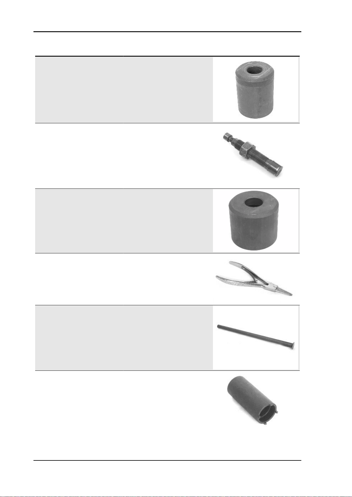
SPECIFIC TOOLING
Stores code Description
001330Y Tool for fitting steering seats
001467Y002 Driver for OD 73 mm bearing
001467Y006 Pliers to extract 20 mm bearings
001467Y007 Driver for OD 54-mm bearings
001467Y008 Pliers to extract 17 mm ø bearings
001467Y017 Driver for OD 36 mm bearings
TOOL - 21
Page 22
Tooling X9 Evolution 500
Stores code Description
001467Y031 Bell
001467Y034 Pliers to extract ø 15-mm bearings
001467Y035 Belle for OD 47-mm bearings
002465Y Pliers for circlips
020004Y Punch for removing fifth wheels from
020055Y Wrench for steering tube ring nut
headstock
TOOL - 22
Page 23

X9 Evolution 500 Tooling
Stores code Description
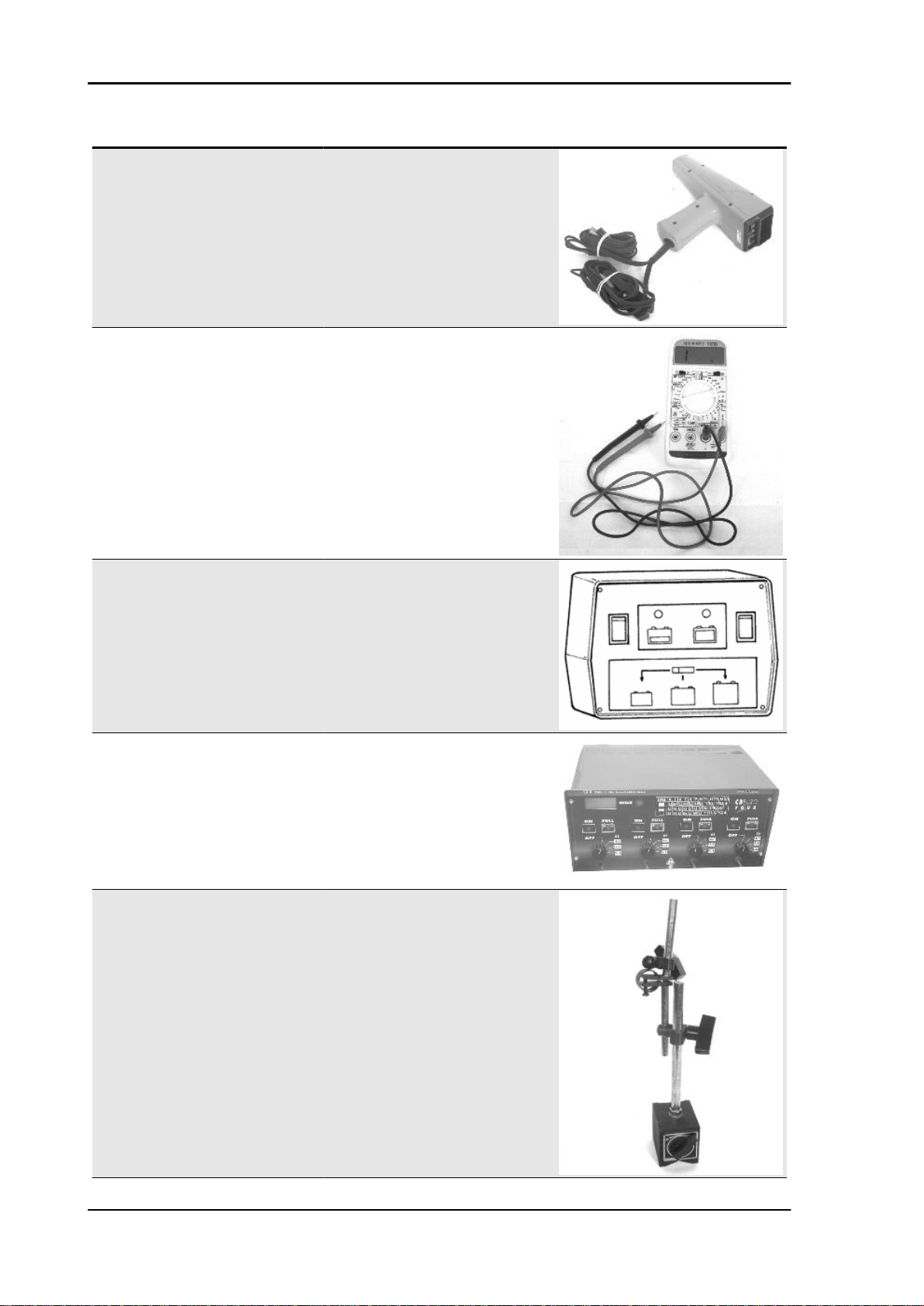
020074Y Support base for checking crankshaft
020150Y Air heater support
020151Y Air heater
alignment
020193Y Oil pressure gauge
020306Y Punch for assembling valve seal rings
020329Y MityVac vacuum-operated pump
TOOL - 23
Page 24
Tooling X9 Evolution 500
Stores code Description
020330Y Stroboscopic light to check timing
020331Y Digital multimeter
020333Y Single battery charger
020334Y Multiple battery charger
020335Y Magnetic support for dial gauge
TOOL - 24
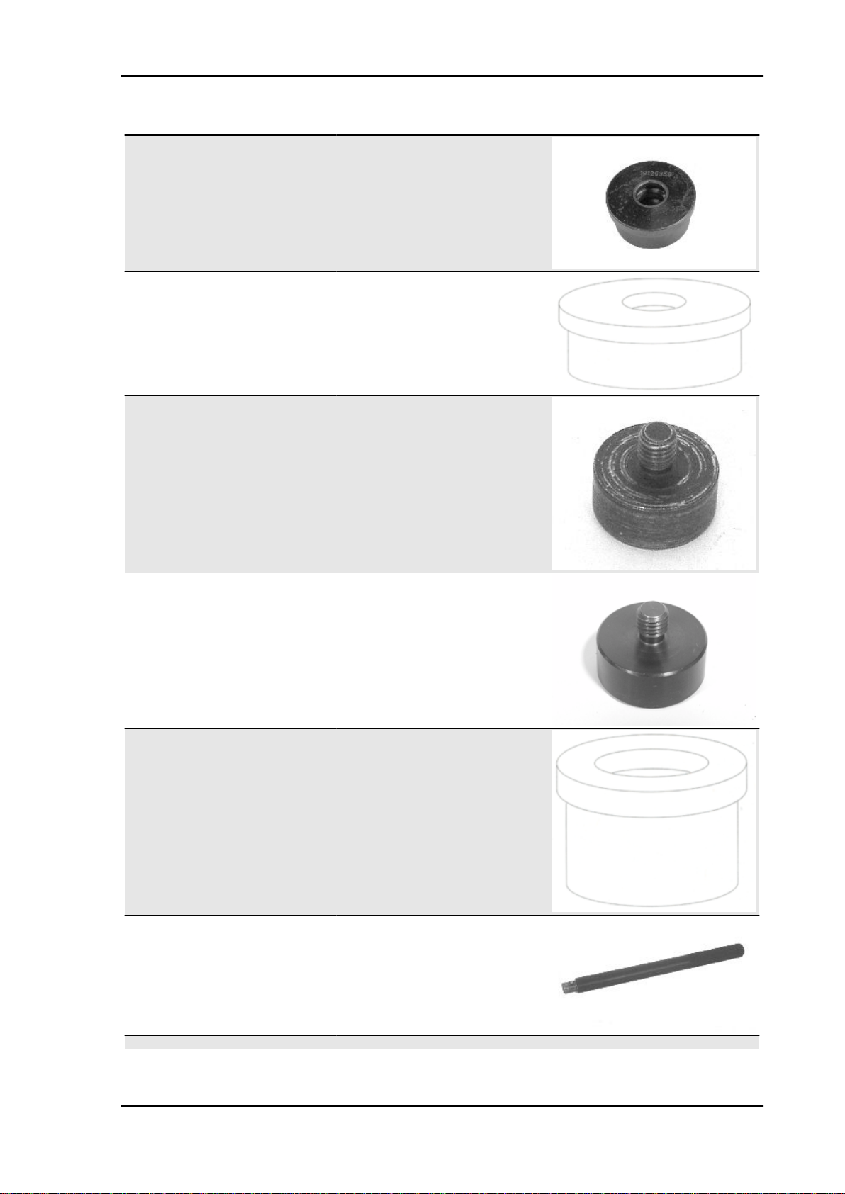
020358Y 37x40-mm adaptor
Page 25
X9 Evolution 500 Tooling
Stores code Description
020359Y 42x47-mm adaptor
020360Y Adaptor 52 x 55 mm
020363Y 20 mm guide
020364Y 25-mm guide
020375Y Adaptor 28 x 30 mm
020376Y Adaptor handle
020382Y012 bush (valve removing tool)
TOOL - 25
Page 26

Tooling X9 Evolution 500
Stores code Description
020412Y 15 mm guide
020431Y Valve oil seal extractor
020434Y Oil pressure control fitting
020439Y 17 mm guide
020444Y Tool for fitting/ removing the driven pulley
clutch
TOOL - 26
Page 27

X9 Evolution 500 Tooling
Stores code Description
020444Y009 46x55 Wrench
020456Y Ø 24 mm adaptor
020458Y Puller for lower bearing on steering tube
020459Y Punch for fitting bearing on steering tube
020460Y Scooter diagnosis and tester
TOOL - 27
Page 28
Tooling X9 Evolution 500
Stores code Description
020467Y Flywheel extractor
020468Y Piston fitting band
020469Y Reprogramming kit for scooter diagnosis
020470Y Pin retainers installation tool
020471Y Pin for countershaft timing
tester
TOOL - 28
Page 29

X9 Evolution 500 Tooling
Stores code Description
020472Y Flywheel lock wrench
020474Y Driving pulley lock wrench
020475Y Piston position checking tool
020476Y Stud bolt set
020477Y Adaptor 37 mm
020478Y Punch for driven pulley roller casing
TOOL - 29
Page 30

Tooling X9 Evolution 500
Stores code Description
020479Y Countershaft lock wrench
020480Y Petrol pressure check set
020481Y Control unit interface wiring
020482Y Engine support
020483Y 30 mm guide
020512Y Piston fitting fork
TOOL - 30
Page 31
X9 Evolution 500 Tooling
Stores code Description
020527Y Engine support base
020565Y Flywheel lock calliper spanner
020604Y011 Fitting adapter
494929Y Exhaust fumes analyser
TOOL - 31
Page 32

INDEX OF TOPICS
MAINTENANCE MAIN
Page 33

X9 Evolution 500 Maintenance
Maintenance chart
Adequate maintenance is fundamental to ensuring long-lasting, optimum operation and performance
of your vehicle.
To this end, a series of checks and maintenance operations (at the owner's expense) have been suggested, which are included in the summary table on the following page. Any minor faults should be
reported without delay to an Authorised Service Centre or Dealer without waiting until the next
scheduled service to solve it.
All scheduled maintenance services must be carried out at the specified intervals, even if the stated
mileage has not yet been reached. Punctual scooter servicing is essential to ensure your warranty
remains valid. For any further information concerning Warranty procedures and "Scheduled Maintenance", please refer to the "Warranty Booklet".
EVERY 2 YEARS
60'
Action
Coolant - change
Brake fluid - change
EVERY 3,000 KM
Action
Engine oil - level check/ top-up
Brake pads - check condition and wear
AFTER 1,000 KM OR 4 MONTHS
90'
Action
Engine oil - replacement
Hub oil - change
Carburetion - check/adjust
Seals/injection system hoses - visual check
Base vent - check
Steering - adjustment
Brake control levers - greasing
Brake fluid level - check
Safety locks - check
Electrical system and battery - check
Vehicle and brake test - road test
MAIN - 33
Page 34

Maintenance X9 Evolution 500
AFTER 6,000 KM OR 12 MONTHS
80'
Action
Engine oil - replacement
Hub oil - level check
Spark plug / electrode gap - check
Air filter - cleaning
Engine oil - change
Valve clearance - check
Base vent - check
Variable speed rollers - replacement
Driving belt - checking
Coolant level - check
Brake fluid level - check
Electrical system and battery - check
Tyre inflation and wear - Check
Vehicle and brake test - road test
AFTER 12,000 KM OR 24 MONTHS AND 60,000 KM
205'
Action
Engine oil - replacement
Hub oil - level check
Spark plug/electrode gap - replacement
Air filter - clean
Engine oil - change
Carburetion - check/adjust
Seals/injection system hoses - visual check
Base vent - check
Variable speed rollers - replacement
Roller support sliding blocks - check/change
Driving belt - replacement
Coolant level - check
Steering - adjustment
Brake control levers - greasing
Transmission elements - lubrication
Brake fluid level - check
Safety locks - check
Suspensions - check
Electrical system and battery - check
Headlight - adjustment
Tyre pressure and wear - check
Vehicle and brake test - road test
150'
Engine oil - replacement
Hub oil - level check
Spark plug / electrode gap - check
Air filter - change
Engine oil - change
Valve clearance - check
Base vent - check
Variable speed rollers - replacement
Driving belt - checking
Coolant level - check
Radiator - external cleaning/ check
Brake fluid level - check
Electrical system and battery - check
Tyre inflation and wear - Check
Vehicle and brake test - road test
MAIN - 34
AFTER 18,000 KM AND AFTER 54,000 KM
Action
Page 35

X9 Evolution 500 Maintenance
AFTER 24,000 KM
255'
Action
Engine oil - replacement
Hub oil - change
Spark plug / electrode gap - replacement
Air filter - clean
Engine oil - change
Fuel filter - check
Carburetion - check/adjust
Seals/injection system hoses - visual check
Base vent - check
Variable speed rollers - replacement
Roller support sliding blocks - check/change
Driven pulley bushing - check / grease
Driving belt - replacement
Coolant level - check
Steering - adjustment
Brake control levers - greasing
Transmission elements - lubrication
Brake fluid level - check
Safety locks - check
Suspensions - check
Electrical system and battery - check
Headlight - adjustment
Tyre inflation and wear - Check
Vehicle and brake test - road test
AFTER 30,000 KM, 42,000 KM AND 66,000 KM
80'
Engine oil - replacement
Hub oil - level check
Spark plug / electrode gap - check
Air filter - cleaning
Engine oil - change
Base vent - check
Variable speed rollers - replacement
Driving belt - checking
Coolant level - check
Brake fluid level - check
Electrical system and battery - check
Tyre inflation and wear - Check
Vehicle and brake test - road test
365'
Engine oil - replacement
Hub oil - level check
Spark plug/electrode gap - replacement
Air filter - change
Engine oil - change
Valve clearance - check
Carburetion - check/adjust
Seals/injection system hoses - visual check
Base vent - check
Variable speed rollers - replacement
Roller support sliding blocks - check/change
Driving belt - replacement
Coolant level - check
Radiator - external cleaning/ check
Steering - adjustment
Action
AFTER 36,000 KM
Action
MAIN - 35
Page 36

Maintenance X9 Evolution 500
Action
Brake control levers - greasing
Brake fluid hoses - replacement
Transmission elements - lubrication
Brake fluid level - check
Safety locks - check
Suspensions - check
Electrical system and battery - check
Headlight - adjustment
Tyre inflation and wear - Check
Vehicle and brake test - road test
AFTER 48,000 KM
255'
Action
Engine oil - replacement
Hub oil - change
Spark plug / electrode gap - replacement
Air filter - clean
Engine oil - change
Fuel filter - replacement
Carburetion - check/adjust
Seals/injection system hoses - visual check
Base vent - check
Variable speed rollers - replacement
Roller support sliding blocks - check/change
Driven pulley bushing - check / grease
Driving belt - replacement
Coolant level - check
Steering - adjustment
Brake control levers - greasing
Transmission elements - lubrication
Brake fluid level - check
Safety locks - check
Suspensions - check
Electrical system and battery - check
Headlight - adjustment
Tyre inflation and wear - Check
Vehicle and brake test - road test
405'
Engine oil - replacement
Hub oil - change
Spark plug / electrode gap - check / replacement
Air filter - change
Engine oil - change
Fuel filter - check
Valve clearance - check
Carburetion - check/adjust
Seals/injection system hoses - visual check
Base vent - check
Variable speed rollers - replacement
Roller support sliding blocks - check/change
Driven pulley bushing - check / grease
Driving belt - replacement
Coolant level - check
Radiator - external cleaning/ check
Steering - adjustment
Brake control levers - greasing
Brake fluid hoses - replacement
Brake fluid level - check
Safety locks - check
Suspensions - check
MAIN - 36
AFTER 72,000 KM
Action
Page 37
X9 Evolution 500 Maintenance
Action
Electrical system and battery - check
Headlight - adjustment
Tyre inflation and wear - Check
Vehicle and brake test - road test
Transmission elements - lubrication
Spark plug
Check and replacement
CAUTION
THE SPARK PLUG MUST BE REMOVED WITH COLD EN-
GINE. THE SPARK PLUG SHOULD BE CHECKED EVERY
6,000 KM AND REPLACED EVERY 12,000 KM. THE USE OF
NON-CONFORMING IGNITION CONTROL UNITS AND
SPARK PLUGS OTHER THAN THOSE PRESCRIBED CAN
SERIOUSLY DAMAGE THE ENGINE.
Characteristic
Recommended spark plugs:
CHAMPION RG6YC - NGK CR 7 EKB
- Position the scooter on centre stand.
- Open the door on the left side and remove the relevant screw lifting from the lower part in the specific
groove.
- Disconnect the shielded spark plug cap
- Unscrew the spark plug.
- Check the conditions of the spark plug, make sure the insulation is intact, that the electrodes are not
excessively worn or grimy, the conditions of the washer, and measure the distance between the electrodes using the appropriate feeler gauge.
Characteristic
Electrode gap
0.7-0.8 mm
Adjust the gap if necessary, carefully bending the
earth electrode. In the event of irregularity, replace
the spark plug with a recommended type.
- Fit the spark plug with the correct inclination and
manually screw it all the way down, then use the
special spanner to tighten it.
Locking torques (N*m)
Spark plug 12 ÷ 14
- Insert the cap onto the spark plug and proceed with the reassembly operations.
Hub oil
MAIN - 37
Page 38

Maintenance X9 Evolution 500
Check
- Take the vehicle to a flat ground and rest it on the
central stand.
- Unscrew the oil bar «A», dry it with a clean cloth
and reinsert it, screwing it in thoroughly;
- Pull out the bar and check that the oil level is between the MAX and MIX levels indicated on the
bar (see figure); if the level is below the MIN value,
restore the proper amount of oil in the hub.
- Screw the oil bar back on, checking that it is tightly in place.
N.B.
THE NOTCHES ON THE HUB OIL LEVEL BAR, WITH THE
EXCEPTION OF THOSE INDICATING THE MAX AND MIN
LEVEL, REFER TO SOME OF THE MANUFACTURER'S
OTHER MODELS AND HAVE NO SPECIFIC FUNCTION AS
FAR AS REGARDS THIS VEHICLE.
Replacement
- Prepare a suitable container.
- Remove the oil drainage cap «B» and let the oil
drain out completely.
- Tighten the drainage cap again and fill the hub
with oil.
Recommended products
AGIP ROTRA 80W-90 rear oil hub
SAE 80W/90 Oil that exceeds the requirements of
API GL3 specifications
Characteristic
Rear hub oil
250 cc
MAIN - 38
Page 39

X9 Evolution 500 Maintenance
Air filter
- Raise the saddle.
- Remove the piston ring and the battery cover.
- Loosen the 4 mounting screws shown in the figure.
- Loosen the mounting screw located under the intake manifold.
- Replace the air filter and reassemble the various
components, reversing the removal procedure.
MAIN - 39
Page 40

Maintenance X9 Evolution 500
- An inspection and possible cleaning (with compressed air) of the air filter is scheduled every 6000
km in any case.
- The air jet must be directed from the inside to the
outside of the filter (i.e. opposite the direction of
the air flow during normal operation of the engine).
- Any deposits of condensate out of the engine oil
caused by blow-by can be removed via the pipe
shown in the figure.
N.B.
FAILURE TO OBSERVE THE RULES REGARDING CLEANING OF THE FILTER ELEMENT CAN
LEAD TO IMPROPER LUBRICATION OF THE ELEMENT. POOR LUBRICATION AFFECTS THE
FILTERING CAPACITY. EXCESSIVE LUBRICATION AS WITH A SOILED FILTER CAUSES AN
EXCESSIVELY RICH FUEL/AIR MIXTURE.
CAUTION
WHEN TRAVELLING ON DUSTY ROADS, THE AIR FILTER MUST BE CLEANED MORE OFTEN
THAN SHOWN IN THE SCHEDULED MAINTENANCE CHART.
WARNING
DO NOT RUN THE ENGINE IF THE AIR FILTER IS NOT IN PLACE THIS WILL RESULT IN EXCESSIVE WEAR TO ALL THE PARTS OF THE COOLING SYSTEM.
Engine oil
In 4T engines, the engine oil is used to lubricate the distribution elements, the bench bearings and the
thermal group. An insufficient quantity of oil can cause serious damage to the engine.
In all 4T engines, the deterioration of the oil characteristics, or a certain consumption should be considered normal, especially if during the run-in period. Consumption levels in particular can be influenced
by the conditions of use (e.g.: oil consumption increases when driving at "full throttle".
Check
This operation must be carried out with the engine
cold and following the procedure below:
1) Rest the vehicle on the central stand and on a flat ground.
2) Unscrew the cap/dipstick "A", dry it with a clean cloth and reinsert it, screwing it thoroughly.
3) Remove the cap/dipstick again and check that the level is between the max. and min levels; top-up,
if required.
Topping up from the MIN to MAX. level requires around 1700 cc.
If the check is carried out after the vehicle has been used, and therefore with a hot engine, the level
line will be lower; in order to carry out a correct check it is necessary to wait at least 10 minutes after
the engine has been stopped, so as to get the correct level.
MAIN - 40
Page 41

X9 Evolution 500 Maintenance
Oil top up
The oil should be topped up after having checked the level and in any case by adding oil without ever
exceeding the MAX. level.
The restoration level between the MIN and MAX levels implies a quantity of oil of approx. 400 cc.
Engine oil filter
CAUTION
DO NOT DISPOSE OF OIL IN THE ENVIRONMENT. OIL, GASKET AND FILTER SHOULD BE DISPOSED OF ACCORDING TO THE REGULATIONS IN FORCE.
WARNING
AVOID TOUCHING PARTS OF THE ENGINE WHEN HOT, AS THIS MAY CAUSE BURNS.
- Remove the muffler.
- Remove the filler plug.
- Remove and clean the mesh pre-filter of the drain
cap with compressed air.
- Use a belt spanner for filters to remove cartridge
filter "C".
- Make sure the pre-filter and drain cap O-rings are
in good condition.
- Lubricate them and refit the mesh filter and oil
drain cap by tightening to the prescribed torque.
- Refit a new cartridge filter making sure to lubricate the O-ring before fitting, then screw until it
comes into contact with the seal and further tighten
to the prescribed torque.
- Refit the muffler.
- Add recommended engine oil.
MAIN - 41
Page 42

Maintenance X9 Evolution 500
- Start the engine and let it run for a few minutes and then turn it off.
After 5 minutes check the level and top up, if necessary, never exceed the MAX. level.
N.B.
IF THE OIL IS CHANGED WITHOUT CHANGING THE CARTRIDGE FILTER (1ST COUPON) ADD
AROUND 1500 CC OF OIL INSTEAD OF 1700 CC SINCE PART OF THE LUBRICATION CIRCUIT
IS FILLED.
Characteristic
Engine oil:
1700 cm³
Locking torques (N*m)
Engine oil drainage plug 24 ÷ 30 Engine oil filter 12 - 16
Oil pressure warning light
The vehicle is equipped with a warning light on the
instrument panel that lights up when the key is
turned to the «ON» position. However, this light
should switch off once the engine has been started.
If the light turns on during braking, at idling
speed or while turning a corner, it is necessary
to check the oil level and the lubrication system.
Checking the ignition timing
- Using a TORX wrench, remove the timing check
cap located on the flywheel cover.
- Remove the transmission cover to access the
driving pulley fastening nut that allows the driving
shaft rotation.
- Remove the head cover as described in the Thermal unit and timing system chapter.
- Turn the driving shaft to make the reference located on the magnet support collimate with that on
the flywheel cover (TDC).
- Make sure that the reference on the wheel speed
sensor is aligned with that obtained on the head.
If the reference is located opposed to the index
MAIN - 42
Page 43

X9 Evolution 500 Maintenance
obtained on the head, make the driving shaft perform a further revolution.
- Check that the two references match perfectly; if
not, remove the timing belt and install it again.
See also
Cylinder assy. and timing system
Checking the valve clearance
- To check the clearance in the valves collimate
the references between the cam shaft control pulley and head.
- Use a feeler to make sure the clearance between
the valve and register screw correspond to the indicated values. If the clearance does not correspond, adjust it by loosening the lock nut using a
screwdriver on the set screw as shown in the figure.
Characteristic
Valve clearance: intake
0.15 mm (when cold)
Valve clearance: discharge
0.15 mm (when cold)
Cooling system
Engine cooling fluid level check
The fluid level inspection should be carried out every 6,000 km when the motor is cold, following the
methods indicated below:
- Rest the vehicle on the central stand and on a flat
ground.
- Remove the expansion tank cap and top up, if the
fluid level is near to or below the MIN level into the
MAIN - 43
Page 44

Maintenance X9 Evolution 500
expansion tank. The fluid level should always be
between the «MIN» and «MAX» level.
- To have an indication of the fluid level, refer to a
notch made in a cylindrical insert, coaxial to the
filler and visible inside it once you remove the
loading cap.
The top side of the notch indicates the MAX level
while the lower one indicates the MIN level.
The cooling fluid consists of a mixture of 50%
demineralised water and ethylene glycol and corrosion inhibitors based anti-freeze solution.
WARNING
TO CHECK THE PRESENCE OF AIR IN THE CIRCUIT, PRO-
CEED AS DESCRIBED IN THE «COOLING» CHAPTER
CAUTION
DO NOT EXCEED THE MAX. LEVEL WHEN FILLING SO AS
TO AVOID THE COOLANT ESCAPING FROM THE EXPANSION TANK WHEN THE vehicle IS IN USE.
Characteristic
Cooling system
approx. 1.8 l
See also
Cooling system
Level check
The front and rear brake fluid tanks can be accessed removing the cover located on the right
side of the handlebar cover and the display PICS
on the left side.
To check the level proceed as follows:
- rest the vehicle on the central stand with the handlebars in a central position;
- remove cover «A» loosening the fixing screw
«B» and check the front brake fluid level;
- remove screws «C» fixing the display PICS and
check the combined brake fluid level;
The level will go down to a certain extent due to
lining wear.
MAIN - 44
Page 45

X9 Evolution 500 Maintenance
Braking system
Level check
- Rest the scooter on a flat ground and on the central stand.
- Remove the brake pump cover as shown in the
figure.
- Check the brake fluid level by the special indicator located on the pump, as shown in the figure.
N.B.
THE LEVEL TENDS TO DROP AS THE BRAKE PADS GET WORN, A MINIMUM LEVEL SHOULD
NOT BE REACHED. IF THE LEVEL IS TOO LOW, CHECK AND FIX THE SYSTEM SEALS, IF RE-
MAIN - 45
Page 46

Maintenance X9 Evolution 500
QUIRED. TOP UP THE PUMP TANK, IF REQUIRED, CONSIDERING THAT THE "MAX." LEVEL
MUST ONLY BE OBTAINED WITH NEW PADS.
Top-up
To top up the fluid proceed as follows:
Remove the right cover and/or the PICS display,
then remove the tank cap loosening the relevant
two screws, remove the intermediate rubber membrane and restore the level using the prescribed
fluid without exceeding the max level.
CAUTION
ONLY USE DOT 4-CLASSIFIED BRAKE FLUID.
Recommended products
AGIP BRAKE 4 Brake fluid
FMVSS DOT 4 Synthetic fluid
In normal weather conditions, the fluid should be
replaced every 20,000 km or in any case every 2
years.
Never use braking fluid from containers that have
already been opened, or partially used.
CAUTION
THE BRAKE FLUID IS HYGROSCOPIC, THAT IS, IT AB-
SORBS MOISTURE FROM THE SURROUNDING AIR. IF
THE LEVEL OF HUMIDITY IN THE BRAKE FLUID EXCEEDS
A GIVEN VALUE, BRAKING EFFICIENCY WILL BE REDUCED.
CAUTION
AVOID CONTACT OF THE BRAKE FLUID WITH YOUR
EYES, SKIN, AND CLOTHING. IN CASE OF ACCIDENTAL
CONTACT, WASH WITH WATER.
WARNING
BRAKE CIRCUIT FLUID IS VERY CORROSIVE; DO NOT
LET IT COME INTO CONTACT WITH PAINTED PARTS.
N.B.
SEE THE BRAKING SYSTEM CHAPTER WITH REGARD TO
THE CHANGING OF BRAKE FLUID AND THE BLEEDING
OF AIR FROM THE CIRCUITS.
Headlight adjustment
- Place the vehicle in use conditions, with no load, with tyres inflated at the prescribed pressure on flat
ground at 10 m from a white screen placed in dim light, making sure that the vehicle's axle is perpendicular to the screen.
- Trace a horizontal line on the screen at 70 - 73 cm above ground level.
MAIN - 46
Page 47

X9 Evolution 500 Maintenance
- Turn the headlight on, switch on the dipped beam
and check that the horizontal limit line between the
dark zone and the illuminated zone does not fall
above the horizontal line traced on the screen.
- Adjust the screw located under the front shield to
change the headlight inclination and the light beam
height.
Checking the end compression pressure
- With the engine cold remove the sparkplug cap.
- Remove the sparkplug.
- Fit a compression testing pressure gauge in the sparkplug seat with a 10 mm sparkplug fitting tightened
to the correct torque.
- With the switch on "ON" wait a few seconds and then disconnect the rpm-timing sensor to disable
operation of the injector and sparkplug.
- Run the engine using the starter motor and with the throttle body fully open, until the reading on the
pressure gauge is stable.
- If the pressure is greater than XX - XX, remove the device and reassemble the vehicle.
- If pressure values lower than those indicated are measured, check the engine rpm used for the test;
if under 450 rpm, check the starter system.
When the compression end pressure is under the norm, remove the fitting from the pressure gauge and
pour a few cc of oil in the combustion chamber, rotate the engine (preferably by hand) to lubricate the
cylinder.
Repeat the pressure test:
if the new values are still low check the valve seals.
Higher pressure values of a new engine indicate poor sealing of the parts.
Locking torques (N*m)
Spark plug 12 ÷ 14
MAIN - 47
Page 48

Maintenance X9 Evolution 500
MAIN - 48
Page 49

INDEX OF TOPICS
TROUBLESHOOTING TROUBL
Page 50

Troubleshooting X9 Evolution 500
Transmission and brakes
Clutch grabbing or performing inadequately
IRREGULAR CLUTCH PERFORMANCE OR SLIPPAGE
Possible Cause Operation
Faulty clutch Check that there is no grease on the masses. Check that the
clutch mass contact surface with the casing is mainly in the
centre with equivalent characteristics on the three masses.
Check that the clutch casing is not scored or worn in an anom-
alous way
Insufficient braking
INSUFFICIENT BRAKING
Possible Cause Operation
Inefficient braking system Check the pad wear (1.5 min). Check that the brake discs are
Fluid leakage in hydraulic braking system Failing elastic fittings, plunger or brake pump seals, replace
not worn, scored or warped. Check the correct level of fluid in
the pumps and change brake fluid if necessary. Check there is
no air in the circuits; if necessary, bleed the air. Check that the
front brake calliper moves in axis with the disc.
Brakes overheating
Possible Cause
Rubber gaskets swollen or stuck Replace gaskets.
Compensation holes on the pump clogged Clean carefully and blast with compressed air
Brake disc slack or distorted Check the brake disc screws are locked; use a dial gauge and
Defective piston sliding Check calliper and replace any damaged part.
Braking vibrations or noise
VIBRATIONS OR NOISE WHEN BRAKING
Possible Cause
Brake disc slack or distorted Check the brake disc screws are locked; use a dial gauge and
Electrical system
BRAKES OVERHEATING
Operation
a wheel mounted on the vehicle to measure the axial shift of
the disc.
Operation
a wheel mounted on the vehicle to measure the axial shift of
the disc.
TROUBL - 50
Page 51

X9 Evolution 500 Troubleshooting
Battery
BATTERY
Possible Cause Operation
Battery This is the device in the system that requires the most frequent
Turn signal lights malfunction
TURN INDICATOR NOT WORKING
Possible Cause Operation
Electronic ignition device failure With the key switch set to "ON" jump the contacts 1 (Blue -
attention and the most thorough maintenance. If the vehicle is
not used for some time (1 month or more) the battery needs to
be recharged periodically. The battery runs down completely in
the course of 3 months. If the battery is fitted on a motorcycle,
be careful not to invert the connections, keeping in mind that
the black ground wire is connected to the negative terminal
while the red wire is connected to the terminal marked+.
Black) and 5 (Red/Blue) on the control unit connector. If by
operating the turn indicator control the lights are not steadily
on, replace the control unit; otherwise, check the cable harness
and the switch.
Steering and suspensions
Controls
STEERING CONTROLS AND SUSPENSIONS
Possible Cause
Torque not conforming Check the tightening of the top and bottom ring nuts. If irregu-
Steering hardening Check the tightening of the top and bottom ring nuts. If irregu-
Malfunctions in the suspension system If the front suspension is noisy, check: the efficiency of the front
Seal fault or breakage Replace the shock absorber Check the condition of wear of the
Operation
larities in turning the steering continue even after making the
above adjustments, check the seats on which the ball bearings
rotate: replace them if they are recessed or if the balls are flat-
tened.
larities in turning the steering continue even after making the
above adjustments, check the seats on which the ball bearings
rotate: replace them if they are recessed or if the balls are flat-
tened.
shock absorbers; the condition of the ball bearings and relevant
lock-nuts, the limit switch rubber buffers and the movement
bushings. In conclusion, check the tightening torque of the
wheel hub, the brake calliper, the shock absorber disk in the
attachment to the hub and the steering tube.
steering covers and the adjustments.
Heavy steering
Torque not conforming Check the tightening of the top and bottom ring nuts.
Possible Cause
STEERING HARDENING
Operation
If irregularities continue in turning the steering even after mak-
ing the above adjustments, check the seats in which the ball
bearings rotate: replace if they are recessed.
TROUBL - 51
Page 52

Troubleshooting X9 Evolution 500
Excessive steering play
EXCESSIVE STEERING CLEARANCE
Possible Cause Operation
EXCESSIVE STEERING CLEARANCE Check the tightening of the top and bottom ring nuts.
If irregularities continue in turning the steering even after mak-
ing the above adjustments, check the seats in which the ball
bearings rotate: replace if they are recessed.
Noisy suspension
NOISY SUSPENSION
Possible Cause Operation
NOISY SUSPENSION If the front suspension is noisy, check: the efficiency of the front
shock absorbers; the condition of the ball bearings and relevant
lock-nuts, the limit switch rubber buffers and the movement
bushings.
Suspension oil leakage
Possible Cause
Oil leakage from suspension Service the pumping members and check the sleeves and
OIL LEAKAGE FROM SUSPENSION
Operation
sealing rings are in good conditions. Replace the damaged
parts
TROUBL - 52
Page 53

INDEX OF TOPICS
ELECTRICAL SYSTEM ELE SYS
Page 54

Electrical system X9 Evolution 500
ELECTRICAL SYSTEM
Specification
1 Outside temperature sensor
2 Rear brake stop button
3 Light switch with flash
4 Indicators switch
5 Horn button
6 Emergency flashing button
7 Front fuse holder box
8 Fuse no.3 7,5A
9 Horn
10 Fuse 15A
11 Side stand switch
12 Intercom connectors
13 Voltage regulator
14 Electric side stand control unit
15 Engine stop remote control switch 30A
16 Remote electronic controller switch 30A
17 No. 2 side stand pump remote control switches
18 Fuse 70A
19 Fuse holder box with side stand pump base
20 LH taillight with sidelights bulb and flashing light bulb
21 Fuse 7,5A
22 Fuse 10A
23 Fuse 5A
24 Fuse 3A
25 No. 2 rear fuse holder boxes for control unit
26 Anti-tilting sensor
27 Saddle opening actuator
28 Intercom control unit
Desc./Quantity
ELE SYS - 54
Page 55

X9 Evolution 500 Electrical system
Specification Desc./Quantity
29 Front left-hand direction indicator with bulb
30 Analogue instrument unit (5 bulbs)
31 Radio display
32 Digital instrument unit with no. 11 LED indicators
33 Front headlight
34 Front right-hand direction indicator with bulb
35 Diode unit
36 Diode 6A
37 Diode 1A
38 Main remote control switch 30A
39 Socket 12V
40 Helmet compartment glass bowl with lamp
41 Rear brake light with no. 5 bulbs
42 Number plate light with bulb
43 RH taillight with sidelights bulb and flashing light bulb
44 Start-up remote control switch
45 Battery 12V-14Ah
46 Helmet compartment light button
47 Starter motor
48 No. 3 7.5A fuses
49 Fuse holder box
50 Fuse 15A
51 HV coil
52 Connector cap
53 Saddle opening button
54 Fuel level indicator with pump
55 Immobilizer aerial
56 Key switch
57 Anti-theft alarm fitting
58 Electric fan
59 Electric fan remote control switch 30A
60 Fitting for accessories
61 Side stand button
62 Start up button
63 Reset button
64 Actuators control unit
65 Engine stop switch
66 Decoder
67 Front brake stop button
68 Wheel rpm sensor
69 Injection ECU
70 Side stand pump motor
71 End of stroke button
72 Enable button
73 No. 2 buttons with clamp
74 Fuel injector
75 Throttle potentiometer
76 Idle adjustment motor
77 Engine rpm sensor
78 Engine rpm sensor
79 Engine water temperature sensor
80 Stuck relay indicator
81 Engine oil pressure sensor
82 Magneto flywheel
WIRING COLOUR CHART:
B = White - Bl = Blue - G = Yellow - Mr = Brown - N = Black - BV = White - Green - GN = Yellow - Black
- G = Grey - Rs Pink - R = Red - Vi = Purple - V = Green - VN = Green - Black - BN = White - Black -
BBl = White - Blue - GV = Yellow - Green - Ar = Orange - Az = Light blue - GrBl = Grey - Blue - GrN
= Grey - Black.
CAUTION
ELE SYS - 55
Page 56
Electrical system X9 Evolution 500
SHOULD ANY INTERVENTIONS TO THE ELECTRIC SYSTEM BE REQUIRED, MAKE SURE THAT
THE LEADS TO THE ELECTRONIC IGNITION DEVICE ARE PROPERLY CONNECTED ACCORDING TO POLARITY AND TO THE LEAD COLOURS.
Components arrangement
COMPONENTS LOCATION
Specification
1 Side stand switch
2 Voltage regulator
3 Side stand control unit
4 Electronic control unit remote control switch
5 Engine stop remote control switch
6 Service remote control switch
7 Fuse holder box (n.3 7.5A, n.1 15A)
8 No. 2 start-up remote control switches
9 Magneto flywheel 373W
10 No. 2 buttons for side stand
11 Side stand pump motor
12 Pump unit with level indicator
13 Starter motor
14 Helmet compartment lighting button
15 Helmet compartment glass bowl
16 Socket 12V
17 No. 2 rear fuse holder boxes for control unit (n.1 3A, n.1
5A, n.1 10A, n.1 3A)
18 (Diode holder box (n. 2 6A and 2A diodes)
19 Fuse holder box (n.2 7.5A, n.1 15A and 5A)
20 Fuse holder box with base for stand pump remote control
switch (n.1 70A)
21 Digital instrument unit (11 indicators and led)
22 Analogue instrument unit (5 bulbs)
23 Headlight with n. 2 position bulbs and n.2 high/low beam
bulbs 55W
24 Front LH direction indicator with 10W bulb
25 Rear brake stop button
Desc./Quantity
ELE SYS - 56
Page 57

X9 Evolution 500 Electrical system
Specification Desc./Quantity
26 Light switch with flash
27 Indicators switch
28 Horn button
29 Emergency flashing button
30 Reset button
31 Horn
32 LH taillight with sidelights bulb 5W and flashing light bulb
33 Rear tail light with 5 2.3W bulbs
34 Number plate light bulb 12V-5W
35 Rh taillight with sidelights bulb 5W and flashing light bulb
36 Battery 12V-14Ah
37 Front brake stop button
38 Engine stop switch
39 Wheel rpm sensor
40 Front RH direction indicator with 10W bulb
41 Main remote control switch
42 Light switch
43 Start up button
44 Side stand button
45 Key switch
46 Radio display
47 Electric fan remote control
48 30A fuse with start-up remote control switch
49 Radio/intercom/handsfree control unit
50 No. 2 pump remote control switches
51 Stuck relay indicator
52 No. 2 headlight remote control switches
10W
10W
Conceptual diagrams
Ignition
ELE SYS - 57
Page 58

Electrical system X9 Evolution 500
IGNITION SECTION
Specification Desc./Quantity
1 Anti-theft alarm fitting
2 Side stand switch
3 Engine stop switch
4 Voltage regulator
5 Battery 12V - 4Ah
6 Start up button
7 Diode 6A
8 Starter motor
9 Fuse no. 13 30 A
10 Remote starter switch
11 Main remote control switch
12 Diode 2 A
13 Key switch contacts
14 Two brake light buttons
15 Digital instrument unit
16 Engine stop remote control switch
17 Electronic control unit remote control switch
18 Immobilizer aerial
19 Decoder
20 HV coil
21 Start-up/injection electronic control unit
22 Fuse no. 2 10 A
23 Fuse no. 3 3A
24 Fuse no. 10 7,5A
Headlights and automatic starter section
HEADLIGHTS AND AUTOMATIC STARTER SECTION
Specification
1 Anti-theft alarm fitting
2 Bulb for upper beams 12V - 55W
3 Bulb for lowerbeams 12V - 55W
ELE SYS - 58
Desc./Quantity
Page 59

X9 Evolution 500 Electrical system
Specification Desc./Quantity
4 Light switch
5 Side stand switch
6 Engine stop switch
7 Voltage regulator
8 Roof lamp for box helmet illumination with lamp
9 Helmet compartment lighting button
10 Battery 12V - 14 Ah
11 Fuse no. 13 30 A
12 Main remote control switch
13 Diode 2 A
14 Key switch contacts
15 No. 2 bulbs for front sidelight 12V-3W
16 License plate light bulb 12V - 5W
17 Two (2) taillight bulbs 12V - 5W
18 Digital instrument unit
19 4 Turn indicator bulbs 12V-10W
20 Indicators switch
21 Emergency flashing light button (4 direction indicators)
22 Engine stop remote control switch
23 Connettore per predisposizione accessori
24 Start-up/injection electronic control unit
25 Fuse no. 5 15 A
26 Fuse no. 8 7,5 A
27 Fuse no. 4 5 A
28 Fuse no. 12 7,5 A
29 Fuse no. 11 7,5 A
30 Fuse no. 9 15 A
Battery recharge and starting
BATTERY RECHARGE AND START-UP SECTION
Specification
1 Side stand switch
2 Engine stop switch
3 Magneto flywheel
Desc./Quantity
ELE SYS - 59
Page 60

Electrical system X9 Evolution 500
Specification Desc./Quantity
4 Voltage regulator
5 Battery 12V - 4Ah
6 Start up button
7 Diode 6A
8 Starter motor
9 Fuse no. 13 30 A
10 Remote starter switch
11 Main remote control switch
12 Diode 2 A
13 Key switch contacts
14 Two brake light buttons
15 No. 5 bulbs for brake light 12V-2,3W
16 Digital instrument unit
17 Control unit power supply remote control switch (engine
18 Start-up/injection electronic control unit
19 Fuse no. 4 5 A
20 Fuse no. 10 7,5A
stop)
Level indicators and enable signals section
LEVEL INDICATORS AND ENABLE SIGNALS SECTION
Specification
1 Anti-theft alarm fitting
2 Side stand switch
3 Engine stop switch
4 Saddle opener actuator
5 Saddle opening button
6 Voltage regulator
7 Key switch contacts
8 Roof lamp for box helmet illumination with lamp
9 Helmet compartment lighting button
10 Battery 12V - 4Ah
11 Fuse no. 13 30 A
12 Main remote control switch
ELE SYS - 60
Desc./Quantity
Page 61

X9 Evolution 500 Electrical system
Specification Desc./Quantity
13 Diode 2 A
14 Key switch contacts
15 Engine warning indicator
16 Engine not enable indicator
17 Low fuel warning light
18 High-beam warning light
19 Wheel RPM sensor
20 Outside temperature sensor
21 Digital instrument unit
22 Fuel level sender
23 Control unit power supply remote control switch (engine
24 Electronic control unit components remote control switch
25 Saddle opener receiver
26 Pump remote control switches
27 Side stand pump motor
28 Stuck relay indicator
29 Side stand out enable button
30 Side stand in enable button
31 Electro-hydraulic side stand actuation button
32 Side stand control unit
33 Tilting sensor
34 Air temperature sensor
35 Engine rpm sensor
36 Double wire screened cable
37 Fuel injector
38 Idle adjustment motor
39 Fuel pump
40 Engine temperature sensor
41 Diagnostics socket connector
42 Throttle potentiometer
43 Start-up/injection electronic control unit
44 Fuse no. 5 15A
45 Fuse no. 6 10A
46 Fuse no. 14 70A
47 Fuse no. 2 10A
48 Fuse no. 1 5A
49 Fuse no. 4 5 A
50 Fuse no. 12 7,5 A
stop)
Checks and inspections
Battery recharge circuit
The recharge system is provided with a three phase alternator with permanent flywheel.
The alternator is directly connected to the voltage regulator.
This, in its turn, is connected directly to the ground and the battery positive terminal passing through
the 30A protective fuse.
This system therefore requires no connection to the key switch.
The three- phase generator provides good recharge power and at low revs, a good compromise is
achieved between generated power and idle stability.
Stator check
Stator winding check-up
WARNING
THIS CHECK-UP CAN BE MADE WITH THE STATOR PROPERLY INSTALLED.
ELE SYS - 61
Page 62

Electrical system X9 Evolution 500
1) Remove the door in the saddle compartment.
2) Disconnect the connector between the stator and regulator with the three yellow wires.
3) Measure the resistance between each of the yellow terminals and the other two.
Electric characteristic
Resistance:
0.2 - 1 Ω
4) Check that there is insulation between the each yellow cable and the ground.
5) If values are incorrect, replace the stator.
Recharge system voltage check
Look for any leakage
1) Check that the battery does not show signs of leaking fluid before checking the output voltage.
2) Turn the ignition key to OFF and connect the multimeter leads between the battery negative pole (-)
and the Black cable.
3) With the multimeter leads connected, disconnect the Black cable from the battery negative pole (-).
4) With the ignition key always at OFF, the reading indicated by the ammeter must be ≤ 0.5 mA.
Maximum current output check.
- With engine off and panel set to "ON" turn on the lights and let the battery voltage set to 12V.
- Connect ammeter pliers to the 2 recharge positive poles in output from the regulator.
- Keep the lights on and start the engine, bring it to normal speed and read the values on the ammeter.
With an efficient battery a value must be detected: > 20A
Check the charging current
WARNING
BEFORE CARRYING OUT THE CHECK, MAKE SURE THAT THE BATTERY IS IN GOOD WORKING ORDER.
1) Place the vehicle on its centre stand
2) With the battery correctly connected to the circuit, place the tester terminals between the battery
terminals..
3) Start the engine, ensure that the lights are all out, increase the engine speed and at the same time
measure the voltage.
Electric characteristic
Voltage ranging between 14.0 and 15.0V at 5000 rpm.
VOLTAGE REGULATOR/RECTIFIER
Specification
Type Non-adjustable three-phase transistor
Voltage 14 ÷ 15V at 5000 rpm with lights off
ELE SYS - 62
Desc./Quantity
Page 63
X9 Evolution 500 Electrical system
Lights list
LIGHTS LIST
Specification Desc./Quantity
1 Dipped beam light N° 1, 12V-55W, halogen
2 Upper beam light N° 1, 12V-55W, halogen
3 Front position lights N° 2, 12V-3W, all glass
4 Front direction indicator lights N° 2, 12V-10W, spherical
5 Rear position lights N° 2, 12V-5W, spherical
6 Stop lights N° 5, 12V-2,3W, spherical
7 Rear turn indicator bulbs Two, 12V-10W, spherical
8 Instrument panel lights N° 5, 12V-2W, all glass
9 Helmet compartment light N° 1, 12V-5W, cylindrical
10 Number plate lights N° 1, 12V-5W, cylindrical
Fuses
The electric system is equipped with:
1. four fuses «A» into the under saddle compartment.
FUSE
Specification
1 N.1 Capacity: 15 A
Protected Circuits : Socket 12V for users- Under sad-
2 N.1 Capacity: 10 A
Protected Circuits : Saddle opening by button
3 N.1 Capacity: 10 A
Protected Circuits : PICS device
4 N.1 Capacity: 7,5 A
Protected Circuits : Dipped and high beam bulb
Desc./Quantity
dle compartment light
2. five fuses «B» next to the battery, on the left side.
FUSE
Specification
1 N.1 Capacity: 70 A
Protected Circuits : Electro-hydraulic stand
2 N.1 Capacity: 5 A
Protected Circuits : Electro-hydraulic stand
3 N.1 Capacity: 10 A
Protected Circuits : Fuel pump - Injector - H.V. coil
4 N.1 Capacity: 3 A
Protected circuits: Immobilizer (Decoder and EMS en-
Desc./Quantity
gine management control unit)
ELE SYS - 63
Page 64

Electrical system X9 Evolution 500
Specification Desc./Quantity
5 N.1 Capacity: 5 A
Protected circuits: Diagnostic outlet - Decoder and
control unit enable signal
3. four fuses «C» into the trunk on the left side.
FUSE
Specification Desc./Quantity
1 N.1 Capacity: 15 A
2 N.1 Capacity: 7,5 A
3 N.1 Capacity: 7,5 A
4 N.1 Capacity: 7,5 A
Protected circuits: Horn - High beam bulb - Accesso-
ries
Protected circuits: Start-up enable signal - Brake light
lamp
Protected circuits: Front and rear position light - Num-
ber plate light
Protected circuits: PICS - Saddle opening by remote
control
4. a 30A fuse (main fuse), located next to the battery on the right side and on the start-up remote
control switch; a spare fuse is provided below it.
ELE SYS - 64
Page 65

X9 Evolution 500 Electrical system
Dashboard
Vehicle X9 is provided with an instrument panel
divided into 2 sections: the analogue section is
fixed into the cap while the digital section is integral
to the handlebar.
The analogue section includes:
- Tachometer with dual scale (MPH/KMH) controlled by the fifth wheel by the digital section;
- RPM counter controlled by the signal sent by the
injection control unit;
- Fuel level indicator controlled by a resistive sensor (into the tank)
- Cooling fluid temperature indicator controlled by
a resistive sensor (on the head)
These instruments are electrical and managed by
stepping motors.
The digital section has the following indications:
- Fuel reserve: amber coloured;
- Position and dipped beam lights: green coloured;
- Upper or passing beams: blue coloured;
- Left direction indicator: green coloured;
- Right direction indicator: green coloured;
- Emergency lights (four direction indicators): red
coloured;
- Engine disabled: red coloured;
- ABS system failure (optional): red coloured;
- Oil pressure: red coloured;
- Injection warning: amber coloured;
- ALARM (electro-hydraulic stand): red coloured.
The fuel reserve, direction indicators and emergency flashing functions are activated by the instrument
electronics. For example, the fuel reserve indicator light only turns on when the reserve indication coming from the engine lasts at least 13.5 seconds. This prevents the intermitting turning on of the reserve
light indicator.
- The intermitting function is built in the instrument electronics: this allows operating the emergency
lights with switch in position "OFF" and control switch off. The control switch is only active when the
instrument panel is on.
ELE SYS - 65
Page 66

Electrical system X9 Evolution 500
To ensure safety while riding, the "direction indicators control" function is connected to the odometer.
If the indicator is left on, it automatically stops after 1 kilometre travelled.
- The "engine disabled" indicator is activated by the side stand switch and by the emergency switch on
the right side of the handlebar.
- The LCD display gives a 5 digit indication for the total kilometres covered by the vehicle. It can be
expressed in kilometres or in miles: of course, this indication cannot be reset. To select the indication,
press "Trip" and "M" at the same time, then tirn the key switch to "ON"; keep these 2 buttons
pressed for more than 3" to display "SET" on the display, then the display switches from miles
to kilometres, or vice versa.
The instrument panel digital section is completed
by a liquid crystal display and 4 control buttons.
The display has 3 icons:
- Oil
- Service
- Belt
- The "Oil" icon warns the user of the need of replacing the engine oil.
- The "Service" icon warns the user of the need of servicing the vehicle.
- The "Belt" icon warns the user of the need of replacing the driving belt.
After servicing by the authorised workshop, the icon message must be reset by the "Reset" button
located in the front side of the vehicle under the headlight upper cover. The "Reset" button allows
resetting the kilometres covered and, in the case of "OIL" and "BELT" and "SERVICE", also the year
count. This count remains active even if the battery is disconnected for a short time.
To reset one of the icons, press the "Reset" button for less than a second, then on the icon
before that to be reset press "Reset" for at least 3" so as to display:
- The selectionj of the desired icon through the relevant solid light.
- The flashing of this light confirms the reset.
- For example, to reset the "Service" icon, go to "Oil" and press the "Reset" button for at least 3". To
reset "Oil", repeat the above procedure going to "Belt".
This procedure must be repeated since the selection of the icon and its reset are operations to be made
at the same time (it is not possible to view the desired function and reset by two different button pressures since in this way the next icon would be reset).
Data check function
The date must be adjusted upon the vehicle delivery to the customer. This is because the clock starts
counting the year for the «Service» function. If the clock has already been started, reset the functions
ELE SYS - 66
Page 67

X9 Evolution 500 Electrical system
«Oil», «Service» and «Belt». The calendar is programmed from 2000 to 2050, to adjust the date and
time use the two buttons «Clock» and «Set».
To guarantee the vehicle safety, every time the key switch is set to «ON», all of the digital indications
are checked.
The digital section also has a functional check of the 4 analogue instruments and of the flashing light
control. To start this check, keep buttons «Clock» and «Set» pressed and set the key switch to
«ON». Within 4 seconds, the software version is displayed, the instruments indicate the scale bottom
and the direction indicators turn on.
At the end of the above procedure, there is the normal check of the indicator lights.
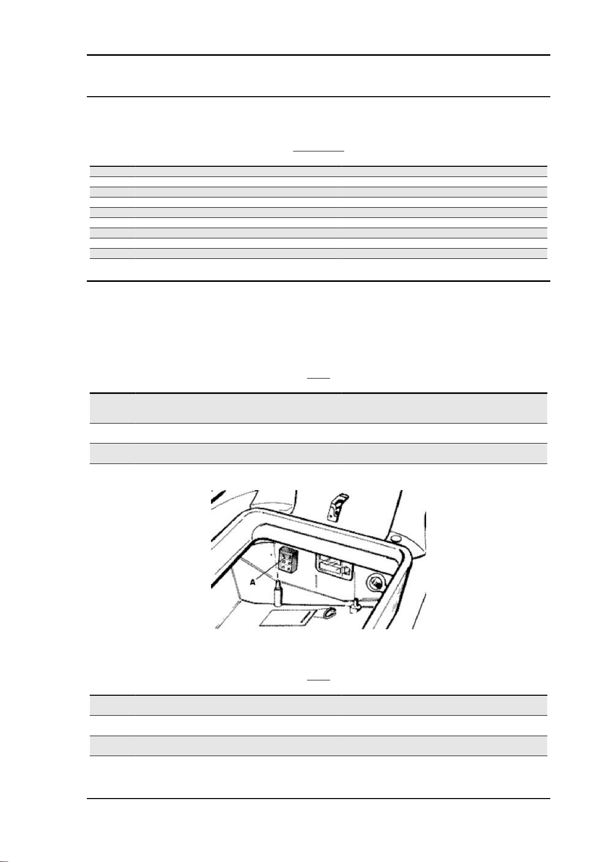
pics
PICS SECTION
Specification
1 Display pics
2 Intercom Controller
3 Intercom connectors
4 Battery 12V - 4Ah
5 Fuse no. 13 30 A
6 Key switch contacts
7 Fuse no. 7 10A
8 Fuse no. 12 7,5 A
Desc./Quantity
ELE SYS - 67
Page 68
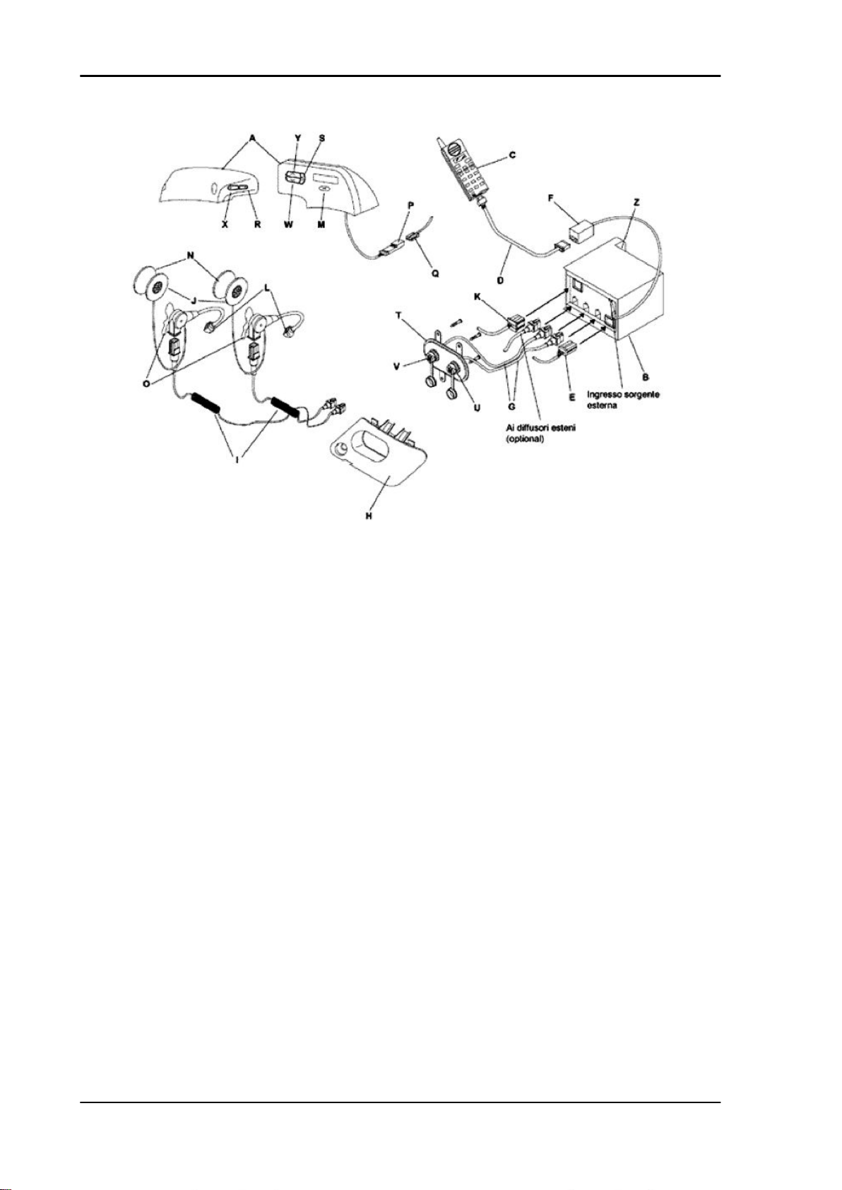
Electrical system X9 Evolution 500
Captions
A = Satellite
D = Mobile phone cable
F = Telephone connector
H = Spark plug inspection port
J = Loudspeaker
L = Microphone
O = Headset clip
R = Volume button-
U = Passenger connection
X = Volume button +
B = Control unit
E = Control unit power supply connector
K = Vehicle control unit connector
M = MODE button
P = Satellite connector
S = Selection button
V = Pilot connection
Y = UP button
C = Mobile phone
G = Control unit audio connection cables
ELE SYS - 68
Page 69

X9 Evolution 500 Electrical system
I = Headset cables
N = Loudspeaker
Q = Vehicle satellite connector
T = Cable support plate
W = DOWN button
Z = Fixing of control unit to chassis
The control unit PICS X9 (B) combines in a single product the traditional function of intercom for motorriders and that of hadsfree kit for mobile phones and RDS radios.
The voice activation of the intercom function allows eliminating the ground noise caused by the wind It
can be enabled both in automatic and manual mode selecting the two available levels high/low.
Without passenger, the control unit can be used by the pilot as telephone handsfree and/or to listen to
the radio or to the external audio source.
The phone talk sets automatically to the pilot when the call signal is detected, but it can be switched to
the passenger and/or vice versa by the button (Y) located on the satellite.
The listening volume is adjusted by hand using buttons (R) and (X) for the two loudspeakers; this
adjustment affects the audio, intercom and telephone.
The control unit is provided with an auxiliary audio socket for a portable CD or cassette reader.
During the telephone conversation, the external source is disconnected from the conversation channel
and is restored at the end of the same.
The control unit is adapted to specific mobile phones by the telephone cable (D) (supplied separately).
N.B.
THE MOBILE PHONE-CONTROL UNIT INTERFACE CABLE IS AVAILABLE FOR MOST MOBILE
PHONES AVAILABLE ON THE MARKET. CHECK THE AVAILABILITY OF THE INTERFACE CABLE FOR YOUR SPECIFIC MOBILE PHONE AT THE CONCESSIONAIRE'S.
The microphone stem is provided with an elastic
metal clip to fix it to the bottom edge of the helmet,
on the right side.
The loudspeaker (J) is fixed inside the helmet, at
the ear height, by an attachment velcro (N).
To optimise the intercom communication quality:
- For crash helmets, bend the microphone stem so
that the capsule is fully seated into the helmet, with
the white identification spot (see figure 2) facing
the mouth.
- For open helmets, bend the microphone stem so that the capsule sensitive part is as close as possible
to the mouth, using the white identification spot (see figure).
WARNING
ELE SYS - 69
Page 70

Electrical system X9 Evolution 500
DON'T REMOVE THE MICROPHONE CAPSULE PROTECTION.
Insert both headsets into the connectors; the pilot's is the front one, the passenger's is the rear one.
Move the ignition key to ON and the intercom will start automatically, at the low level (LOW); the intercom
can be started in manual mode too.
Adjust the volume using buttons (X) (R).
The voice activation level can be switched to two levels (high; low).
In automatic mode, the intercom starts automatically when the pilot or the passenger talk, and it remains
active for 20 seconds at the end of the talk (be careful to the level set).
To switch it to the high level (HIGH), press button (M) and then button (S) when the radio function is
displayed.
A mobile phone can be connected to the device using the special cable (D) (see Piaggio accessories);
when a call is received, a tone is heard by both the passenger and the pilot; after the tone, the call is
switched to the pilot, with the possibility of switching it to the passenger by button (Y). The call can be
temporarily interrupted by button (W) to switch to the intercom, and then resumed pressing the same
button.
In any case, when the call is received, the control unit emits a short sound on both loudspeakers,
optionally with the phone's tone, if the phone model has one.
When the vehicle is stopped, if a call is in progress the control unit remains on until the conversation is
ended.
The mobile phone should be set to the automatic answer function to prevent having to press a key to
start the conversation.
For the models not provided with this function: you can select the answer by any key option.
The conversation volume can only be set by the mobile phone.
The volume should be set to maximum.
It is possible to connect a scatterer (2.5 W max) by the external scatterer socket (see figure 1). Besides
the radio, intercom and handsfree kit functions, it is possible to connect the control unit to a portable
CD reader or a walkman by a cable with stereo jack termination 3.5 mm. Adjust the external source
volume so that it can be heard corrctly without having to adjust the intercom volume.
During a conversation in intercom mode, the audio from the radio or from the external source remains
in background at a lower volume.
N.B.
ALWAYS REFER TO THE USE MANUAL OF YOUR MOBILE PHONE TO SET UP THE FUNCTIONS
DESCRIBED ABOVE.
N.B.
THE USERS OF MOTOROLA 8700, STARTAC 130™ CD920 CD930 AND BOSCH M-COM 506
MUST CONNECT THEIR MOBILE TO THE CONTROL UNIT WITH PHONE OFF: THE PHONE WILL
SWITCH ON AUTOMATICALLY.
ELE SYS - 70
Page 71

X9 Evolution 500 Electrical system
STARTING (USING THE VEHICLE KEY)
Specification Desc./Quantity
No helmet inserted - Logo X9 Tuner - source - Speakerphone with external speakers
Driver headphone inserted - Driver/passenger helmet - pas-
senger crossed out
Passenger headphone inserted - Driver/passenger helmet -
driver crossed out
Driver and passenger headphones inserted - Driver and pas-
senger helmets
N.B.
EVERY TIME THE KEY SWITCH IS SET TO "ON" THE PICS SYSTEM DISPLAY CHECKS ALL
AVAILABLE ICONS.
TURNING ON/OFF THE DEVICE (VEHICLE RUNNING)
Specification Desc./Quantity
Turn off - M > 4 sec.
Turn on - M > 4 sec.
N.B.
WHEN THE VEHICLE IS STARTED, IF THE DEVICE HAD BEEN TURNED OFF THE ICON CHECK
WILL BE DISPLAYED AND AT THE END OF THIS STEP IT WILL RETURN TO THE PREVIOUS
POSITION (OFF). TO RESTART, PRESS "M" FOR MORE THAN 4 SEC.
Tuner - source - Speakerphone
Tuner - source - Speakerphone
Tuner - source - Speakerphone - Intercom
MANUAL INTERCOM
Specification
Activation - M two times Short
Deactivation - M two times Short
N.B.
AFTER MANUAL DISABLING, THE INTERCOM SWITCHES TO AUTOMATIC MODE WITH LESS
SENSITIVE ENABLE LEVEL (LOW).
Desc./Quantity
TUNER/SOURCE
Specification
Radio on - S Short
Radio off - S Short
Source on - M go after S Short, > 2 sec.
Source off -M go after S short, > 2 sec
Manual tuning UP - M go after ^ Short, Continuous
Manual tuning DOWN -M go after ^ short, continuous
Automatic tuning UP - M go after ^ Short, Continuous
Automatic tuning DOWN -M go after ^ short, short
Memory scanning UP - ^ Short
Memory scanning DOWN - v Short
AUTOSTORE memorization - ^ > 2 sec.
RDS - M go after vol + (AF - TA - PTY) Short, Short
PTY functions (can only be selected after enabling PTY) - Vol.
-
Manual station memorization - Select station* go after S** go
after ^ o V (select station) and after S (to confirm)
Desc./Quantity
Short
> 4 sec., short, short
* By automatic or manual tuning described above
** Press until the display flashes
N.B.
THE BUTTONS MUST BE PRESSED IN A SEQUENCE NOT AT THE SAME TIME.
RDS Radio Data System
ELE SYS - 71
Page 72

Electrical system X9 Evolution 500
Several functions are provided but few of them are used correctly. Basic functions as the AF (alternative
frequencies), that allow listening to a fixed radio station on most of the territory during a journey, are
not always used properly. The same also applies to traffic news.
AF Alternative Frequencies
This allows the receiver to automatically tune on an alternative frequency stronger than the currently
listened by relating to the same station.
TA Traffic Announcement identification
When the traffic news are on air, the function starts and interrupts any other radio stations to listen to
the traffic news. You must be tuned on the station that transmits the news.
PTY Program Type
This allows identifying different types of music programs, to listen to the news, etc. There will be: News,
Affairs, Info, Sport ecc.
Specification Desc./Quantity
Driver-passenger conversation passage - ^ Short
Intercom-telephone passage - v Short
Volume adjustment
icon
Headphone inserted
icon
Passenger headphone
not inserted icon
SPEAKERPHONE TELEPHONE
Driver headphone not
inserted icon
ELE SYS - 72
Page 73

X9 Evolution 500 Electrical system
Intercom on icon
Manual intercom icon
Incoming call icon
Incoming call icon only
with driver headphone
inserted.
Incoming call icon only
with passenger head-
phone inserted.
Telephone call with
driver icon
Telephone call with
passenger icon
Telephone conversation intercom icon
SPECIFICHE TECNICHE
Specification
1 Power 10.5V ÷ 16V
Desc./Quantity
1.4 A max
ELE SYS - 73
Page 74

Electrical system X9 Evolution 500
Specification Desc./Quantity
2 Key 10.5V ÷ 16V
3 Maximum output power 500 mW per channel
4 Power consumption vehicle off ~0 mA
5 Frequency response audio 200 Hz - 20 kHz ± 3 dB
intercom 200 Hz - 5 kHz ± 3 dB
6 Microphones -69 dB ± 3 dB one-way
7 Frequency response: audio 200 Hz ÷ 20 kHz ± 3 dB
8 Loudspeakers 8 Ω - 0.5 mΩ
1.5 mA max
in stand-by ~280 mA
at maximum power ~500 mA
Sealed battery
Airtight battery start-up operations
If the vehicle is provided with an airtight battery, the only maintenance required is the check of its charge
and recharging, if needed.
These operations should be carried out before delivering the vehicle, and on a six-month basis for
storage with open circuit.
Besides upon pre-delivery it is therefore necessary to check the battery charge and recharge it, if required, before storing the vehicle and afterwards every six months.
INSTRUCTIONS FOR THE RENEWAL RECHARGE AFTER OPEN-CIRCUIT STORAGE
1) Voltage check
Before installing the battery on the vehicle, perform an open-circuit voltage check using a conventional
tester.
- If voltage exceeds 12.60 V, the battery may be installed without any renewal recharge.
- If voltage is below 12.60 V, a renewal recharge is required as explained at 2).
2) Constant-voltage battery instructions
- Constant voltage charge equal to 14.40-14.70V
- Initial charge current equal to 0.3-0.5 x rated capacity
- Charge time:
- Recommended 10-12
- Minimum 6 h
- Maximum 24 h
Constant-current battery instructions
- Charge current equal to 1/10 of the battery rated capacity
- Charge time: 5 h
WARNING
WHEN THE BATTERY IS REALLY FLAT (WELL BELOW 12.6V) IT MIGHT OCCUR THAT 5 HOURS
OF RECHARGING ARE NOT ENOUGH TO ACHIEVE OPTIMAL PERFORMANCE.
GIVEN THESE CONDITIONS IT IS HOWEVER ESSENTIAL NOT TO EXCEED 8 HOURS OF CONTINUOUS RECHARGING SO AS NOT TO DAMAGE THE BATTERY ITSELF.
Recharging the battery
Normal bench charging must be performed using the specific battery charger (single) or (multiple),
setting the battery charge selector to the type of battery that requires recharging (i.e., at a current equal
ELE SYS - 74
Page 75

X9 Evolution 500 Electrical system
to 1/10 of the battery rated capacity). Connections to the power supply source must be implemented
by connecting corresponding poles (+ to + and - to - ).
Specific tooling
020333Y Single battery charger
020334Y Multiple battery charger
Cleaning the battery
The battery should always be kept clean, especially on its top side, and the terminals should be coated
with vaseline.
CAUTION
NEVER USE FUSES WITH A CAPACITY HIGHER THAN THE RECOMMENDED CAPACITY. USING
A FUSE OF UNSUITABLE RATING MAY SERIOUSLY DAMAGE THE VEHICLE OR EVEN CAUSE
A FIRE.
CAUTION
CHARGE THE BATTERY BEFORE USE TO ENSURE OPTIMUM PERFORMANCE. INADEQUATE
CHARGING OF THE BATTERY WITH A LOW LEVEL OF ELECTROLYTE BEFORE IT IS FIRST
USED SHORTENS THE LIFE OF THE BATTERY.
If the scooter is not used for a given time (1 month or more) it will be necessary to periodically recharge
the battery.
The battery runs down completely in the course of three months. If it is necessary to refit the battery in
the vehicle, be careful not to reverse the connections, remembering that the ground wire (black) marked
(-) must be connected to the negative clamp while the other two red wires marked (+) must be connected to the clamp marked with the + positive sign.
Dry-charge battery
- BATTERY ELECTROLYTE IS TOXIC AND IT MAY CAUSE SERIOUS BURNS. IT CONTAINS SULPHURIC ACID. AVOID CONTACT WITH EYES, SKIN AND CLOTHING.
IN CASE OF CONTACT WITH EYES OR SKIN, RINSE WITH ABUNDANT WATER FOR ABOUT 15
MINUTES AND SEEK MEDICAL ATTENTION AT ONCE.
IF IT IS SWALLOWED, IMMEDIATELY DRINK LARGE QUANTITIES OF WATER OR VEGETABLE
OIL. SEEK IMMEDIATE MEDICAL ATTENTION.
THE BATTERIES PRODUCE EXPLOSIVE GAS; KEEP THEM AWAY FROM NAKED FLAMES,
SPARKS AND CIGARETTES. VENTILATE THE AREA WHEN RECHARGING INDOORS.
ALWAYS WEAR EYE PROTECTION WHEN WORKING IN THE PROXIMITY OF BATTERIES.
KEEP OUT OF THE REACH OF CHILDREN
- Lift the seat.
- Remove the two screws and the seat lock cover.
- Loosen the two Allen screws, pull the rear cover
upwards and detach the stop light wiring.
- Remove the securing belt and the plastic cover.
- Remove the battery by detaching the negative (-)
terminal first, followed by the positive one (+).
ELE SYS - 75
Page 76
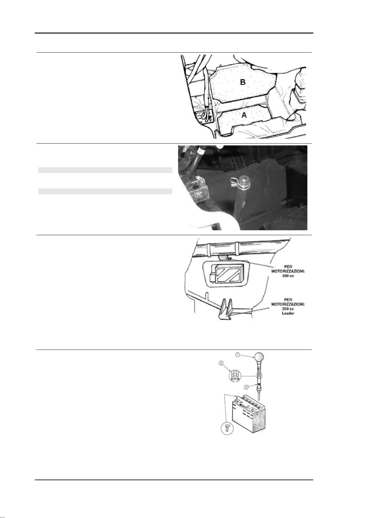
Electrical system X9 Evolution 500
- Insert the lower panel at the bottom of the battery
compartment (A).
- Insert the front element (B).
- Place the battery fixing the vent pipe by the retaining clip.
N.B.
THE VENT PIPE WITH THE RETAINING CLIP ARE AL-
READY MOUNTED ON THE VEHICLE.
N.B.
AFTER RECHARGING AND BEFORE INSTALLING, EN-
SURE THAT THE BATTERY ELECTROLYTE DOES NOT
EXCEED THE MAX LEVEL.
The figure shows two front hooks for the battery
retaining belt:
The top one, obtained in the chassis metal crosspiece, must be used for version 500 cc.
• Position the battery and fit the plastic cap, then lock by the plastic belt.
• Connect the wires to the battery terminals.
- Remove the short closed tube and the caps, then
pour sulphuric acid into the cells using the type
specified for batteries with a specific gravity of
1.26, corresponding to 30 Bé at a minimum temperature of 15°C until the upper level is reached.
- Allow to stand for at least 2 hours, then top up the
level with sulphuric acid.
- Within 24 hours, recharge using the special battery charger (single) or (multiple) at an intensity of
about 1/10 of the battery nominal capacity and until
ELE SYS - 76
Page 77

X9 Evolution 500 Electrical system
the acid gravity is about 1.27, corresponding to 31
Bé and such values become steady.
- After charging, top up the acid (adding distilled
water). Close and clean carefully.
- After carrying out the operations above, install the
battery on the scooter, observing the connections
described in point 3) of paragraph "Battery re-
charge".
Specific tooling
020333Y Single battery charger
020334Y Multiple battery charger
1 Keep the pipe in vertical position
2 Inspect visually
3 The float must be freed
Checking the electrolyte level
The electrolyte level must be checked frequently and must reach the upper level. Only use distilled
water, to restore this level. If it is necessary to add water too frequently, check the vehicle's electrical
system: the battery works overcharged and is subject to quick wear.
Charging status check
After topping-up the electrolyte level, check its density using special density gauge.
When the battery is charged, you should detect a density of 30 to 32 Bé corresponding to a specific
weight of 1.26 to 1.28 at a temperature of no lower than 15° C.
A density reading of less than 20° Bé indicates that the battery is completely flat and it must therefore
be recharged.
If the scooter is not used for a given time (1 month or more) it will be necessary to periodically recharge
the battery.
The battery runs down completely in the course of three months. When refitting the battery onto the
scooter pay attention not to invert the cables, bearing in mind that the earth (black) wire marked with
a (-) must be connected to the negative terminal whilst the other two red wires, marked with a (+) must
be attached to the positive, + terminal.
Battery recharge
WARNING
BEFORE RECHARGING THE BATTERY, REMOVE THE PLUGS OF EACH CELL. KEEP SPARKS
AND NAKED FLAMES AWAY FROM THE BATTERY WHILE RECHARGING.
Remove the battery from the vehicle removing the negative clamp first.
Normal bench charging must be performed using the special battery charger (single) or (multiple), setting the battery charge selector to the type of battery that requires recharging (i.e., at a current equal
ELE SYS - 77
Page 78

Electrical system X9 Evolution 500
to 1/10 of the battery rated capacity). Connections to the power supply source must be implemented
by connecting corresponding poles (+ to + and - to - ).
Specific tooling
020333Y Single battery charger
020334Y Multiple battery charger
The battery should always be kept clean, especially on its top side, and the terminals should be coated
with Vaseline.
CAUTION
NEVER USE FUSES WITH A CAPACITY HIGHER THAN THE RECOMMENDED CAPACITY. USING
A FUSE OF UNSUITABLE RATING MAY SERIOUSLY DAMAGE THE VEHICLE OR EVEN CAUSE
A FIRE.
CAUTION
ORDINARY AND DRINKING WATER CONTAINS MINERAL SALTS THAT ARE HARMFUL FOR
THE BATTERY. FOR THIS REASON, YOU MUST ONLY USE DISTILLED WATER.
CAUTION
CHARGE THE BATTERY BEFORE USE TO ENSURE OPTIMUM PERFORMANCE. FAILURE TO
CHARGE THE BATTERY ADEQUATELY BEFORE BEING PUT INTO OPERATION WILL LEAD TO
A PREMATURE FAILURE OF THE BATTERY.
Phonic wheel
- Ensure that the tone wheel is correctly installed on the scooter and connected to the electrical system.
- Turn the key switch to "ON".
- Access the tone wheel connector on the system side.
- Carry out the following measurements using the special tool.
Specific tooling
020331Y Digital multimeter
Check the supply voltage.
Keeping the connector in the position shown in the
photo, check for battery voltage (12 V) with the
polarity shown.
If incorrect values are measured, check the electrical system and the digital instrument.
N.B.
A DROP IN VOLTAGE OF 1 V IN RELATION TO THE BAT-
TERY VOLTAGE CAN BE CONSIDERED NORMAL.
ELE SYS - 78
Page 79

X9 Evolution 500 Electrical system
Check the signal
Move the positive rod to the position shown in the
photo. Turn the front wheel very slowly and check
that the measured voltage is 0 V or battery voltage,
depending on the position taken up.
This condition should be repeated 16 times during
a complete revolution of the wheel.
N.B.
THE DIGITAL MULTIMETER IS NOT ABLE TO DISPLAY
THE VOLTAGE WHEN THE WHEEL IS ROTATED FAST.
If other voltages are measured or there is no alternation, replace the tone wheel.
Connectors
ECU
DIGITAL DASHBOARD CONNECTOR AND WIRING
Specification
1 Analogue card negative
2 Battery positive (+30) for analogue card
3 Analogue card serial clock output
4 Antitheft led output
5 Analogue card serial data output
6 Lights on output
7 (Not connected)
8 (Not connected)
9 Warning light input
10 Stuck relay alarm light input
11 Abs indicator input (not connected)
12 RH direction indicator output
13 RH direction indicator button input
14 LH direction indicator button input
Desc./Quantity
ELE SYS - 79
Page 80
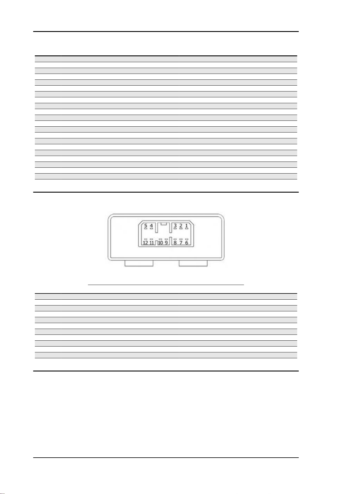
Electrical system X9 Evolution 500
Specification Desc./Quantity
15 Upper beam indicator input
16 Air temperature sensor input
17 Engine not actuable input
18 Oil pressure indicator input
19 (Not connected)
20 LH direction indicator output
21 Direction indicator stop button input
22 Reset service management button input
23 Water temperature sensor input
24 Fuel level sensor input
25 Battery positive (+30)
26 Tachometer sensor power supply
27 Tachometer sensor return to ground
28 Rpm sensor input
29 Battery positive (+30)
30 Antitheft led
31 Key positive (+15)
32 Tachometer sensor input
33 Negative
34 Air temperature sensor return to ground
35 Emergency light button input (hazard)
36 Lights on input
Seat opening receiver
RECEIVER CONTROL UNIT FOR SADDLE OPENER
Specification
1 Radio aerial
2 Actuator positive output 1
3 Reset / Input clearing
4 Battery positive
5 (Not connected)
6 Live positive lead
7 Ground lead
8 (Not connected)
9 (Not connected)
10 Selection input CH1 / CH3
11 Positive output actuator 1
12 Data for alarm output
Desc./Quantity
ELE SYS - 80
Page 81

X9 Evolution 500 Electrical system
Immobiliser decoder
IMMOBILIZER DECODER
Specification Desc./Quantity
1 2 Immobilizer LED control (negative)
3 Base power supply (positive)
4 Negative
5 6 Electronic control unit EMS (serial)
7 8 Continuous power supply (positive) Immobilizer aerial
Engine rev. sensor
REV SENSOR
Specification Desc./Quantity
1 M: Male
2 F: Female
3 S: Shielding
Analogue odometer
ANALOGUE ODOMETER
Specification Desc./Quantity
1 STEPPER MOTOR A
2 STEPPER MOTOR B
3 STEPPER MOTOR C
4 STEPPER MOTOR D
ELE SYS - 81
Page 82

Electrical system X9 Evolution 500
Remote seat opening
The vehicle is equipped with a remote control to open the saddle.
This remote control is supplied together with the keys and at the manufacturing stage, it has been
programmed to work together with the ECU that control the opening device.
If the remote control is lost, a new one can be requested and reprogram it by resetting the ECU memory
and following the same steps as per programming the immobilizer system in the keys.
Battery replacement
To separate the two half-shells of the remote control, insert a blade or a very thin tip of a screwdriver
into a point of the outside edge, then let it slide
along the entire circumpherence.
- Access the printed circuit and remove the two
batteries from the contact reed.
- Place the new batteries with the positive pole
facing the contact reed.
Characteristic
Batteries used:
CR1616
- Replace the card on the rear half-shell with the
button and the led facing outwards.
- Install the pressure rubber on the button (the direction of installation is only one)
- Make the other half engage snap-wise.
Zeroing
- Remove the metal terminal by pliers and connect
it to earth or to terminal 7 (black), for at least 10
seconds.
- This operation clears all remote controls stored
in the control unit.
N.B.
THE CONTROL UNIT CAN PROGRAMME UP TO 7 REMOTE
CONTROLS.
ELE SYS - 82
Page 83

X9 Evolution 500 Electrical system
Programming
- Remove the front shield to access the saddle
opening reception/control unit.
- In the wiring cover you can see the metal terminal
of the white wire protruding from Pin 3 of the control unit.
- To program, the remote controls, set the key switch to «ON» for 1 to 3 seconds, then set it to «OFF».
- Within 10 seconds, reset the switch to «ON» and within 3 seconds, press the remote control button,
then set to «OFF» again.
- If the saddle opens with this last operation, the programming was successful.
- You can program up to 7 remote controls by the above procedure.
ELE SYS - 83
Page 84

INDEX OF TOPICS
ENGINE FROM VEHICLE ENG VE
Page 85

X9 Evolution 500 Engine from vehicle
Exhaust assy. Removal
- Loosen the two fasteners of the exhaust manifold
from the head.
- Loosen the 3 screws fixing the silencer to the
supporting arm.
- Remove the complete silencer.
N.B.
TO ENSURE THE SEAL OF THE SILENCER-EXHAUST MANIFOLD GROUP, YOU MUST REPLACE
THE GRAPHITE COUPLING GASKET EVERY TIME THESE COMPONENTS ARE DETACHED.
MOREOVER, UPON REASSEMBLY, PREVENT THE EXHAUST PIPE FROM DAMAGING THE NEW
GASKET. CHECK THE JOINT SEAL WITH ENGINE ON TO PREVENT FURTHER TROUBLES.
Removal of the engine from the vehicle
Removal of engine
WARNING
CARRY OUT THESE OPERATIONS WHEN THE ENGINE IS COLD.
- Disconnect the battery
- Remove the underseat compartment.
- Drain the coolant.
- Remove the complete muffler assembly.
- Remove the rear wheel.
- Remove the swinging arm.
- Remove the throttle control transmission.
- Remove the air filter coupling and the collector.
- Disconnect the ground cable from the engine.
- Disconnect the carburettor electrical devices and the starter motor power supply cable.
- Disconnect the fuel delivery and return pipes from the carburettor and the cooling system piping (outlet
from the head and inlet to the thermostat).
ENG VE - 85
Page 86

Engine from vehicle X9 Evolution 500
- Disconnect the HV cable from the spark plug.
- Disconnect the alternator cable from the electrical system of the scooter.
WARNING
BE VERY CAREFUL WHEN HANDLING FUEL.
CAUTION
WHEN INSTALLING THE BATTERY, ATTACH THE POSITIVE LEAD FIRST AND THEN THE NEGATIVE LEAD.
Removing the support arm
- Release the lower fixing bolt of the right shock
absorber from the support arm.
- Loosen the 2 screws fixing the arm to the engine.
- Remove the shim adjustment and release the
wheel axle nut; to prevent rotation, use the integral
brake keeping the LH lever pulled.
- Remove the support arm.
Removal of the lower bolt from LHS shock-absorber
- Remove the bolt shown in the figure.
N.B.
TO REMOVE THE SHOCK ABSORBER SUPPORT, RE-
MOVE THE TWO NUTS FROM THE BRAKE CALIPER SIDE
AND EXTRACT THE SCREWS.
Engine - swing-arm bolt removal
- Suitably support the engine.
- Remove the nut shown in the figure.
- Extract the pin.
- The engine can now be removed.
- Perform the operations for removal in the reverse order according to the proper tightening torques.
CAUTION
BE VERY CAREFUL NOT TO REVERSE THE TWO ACCELERATOR CONTROL TRANSMISSIONS.
CHECK THAT WITH VALVE IN ABUTMENT AGAINST THE REGISTER THERE IS A SMALL
CLEARANCE.
N.B.
ENG VE - 86
Page 87

X9 Evolution 500 Engine from vehicle
CAREFULLY CLEAN THE INJECTOR «T» BRANCH BEFORE REPLACING THE QUICK COUPLINGS.
- Orientate the injector so as to prevent interferences of the electric wiring with the cooling fluid and fuel
pipes.
- Check the engine oil level and top up using the recommended brand, if required.
- Fill the cooling circuit.
- Check that accelerator and electric devices are in good working order.
ENG VE - 87
Page 88

INDEX OF TOPICS
ENGINE ENG
Page 89

X9 Evolution 500 Engine
This section describes the operations to be carried
out on the engine and the tools to be used.
Automatic transmission
Transmission cover
- Using a screwdriver, remove the driven pulley
axle cover near the bottom of the cap.
- Loosen the driven pulley shaft fastening nut using
a misaligned wrench and prevent the pulley shaft
rotation using a machine hexagon bush.
- Remove the nut and the two washers.
N.B.
DUE TO THE HIGH TIGHTENING TORQUE, USING DIFFER-
ENT WRENCHES - SUCH AS A CONVENTIONAL POLYGONAL BUSH - MAY DAMAGE THE HEXAGON OBTAINED
ON THE SHAFT OR BREAK THE BUSH ITSELF.
- Remove the six M6 screws.
ENG - 89
Page 90

Engine X9 Evolution 500
- Remove the four M8 screws.
- Remove the transmission cover.
- Check that the bearing rotates freely, otherwise
replace it.
- Loosen the 4 fastening screws
- Extract the outside plastic transmission cover.
Air duct
- Remove the external transmission cover.
- Unscrew the 4 fastening screws shown in the figure to remove the external air conveyor.
- Remove the transmission cover.
- Unscrew the two screws shown in the figure to
remove the air conveyor.
Locking torques (N*m)
Air conveyor screws 11 ÷ 12
ENG - 90
Page 91

X9 Evolution 500 Engine
Air duct filter
- Remove the external air conveyor.
- Unscrew the 2 fastening screws shown in the figure to remove the conveyor filter.
Removing the driven pulley shaft bearing
- Remove the transmission cover.
- Remove the Seeger ring.
- Place transmission cover on a wood surface and
use the special tool so that it is adequately supported.
- Pull out the bearing using the special tool.
N.B.
BELL MUST BE PLACED INTO THE TRANSMISSION COV-
ER, CLOSE TO THE BEARING SEAT AND THE WOODEN
SURFACE, SINCE WITHOUT BELL THE ENTIRE COVER
STRUCTURE WOULD BEND. NOT ONLY IN THE AREA OF
MAXIMUM STURDINESS.
Specific tooling
001467Y002 Driver for OD 73 mm bearing
020376Y Adaptor handle
020375Y Adaptor 28 x 30 mm
020439Y 17 mm guide
ENG - 91
Page 92

Engine X9 Evolution 500
Refitting the driven pulley shaft bearing
- Heat the transmission cover interior using the
heat gun.
N.B.
BE CAREFUL NOT TO OVERHEAT THE COVER AS THIS
WOULD DAMAGE THE OUTSIDE PAINTED SURFACE.
Specific tooling
020151Y Air heater
- Place the bearing onto the special tool with a little
grease to prevent it from coming out.
- Install the new bearing using the special tool.
N.B.
PROPERLY SUPPORT THE OUTSIDE COVER TO PRE-
VENT DAMAGING THE PAINTED SURFACE.
Specific tooling
020376Y Adaptor handle
020358Y 37x40-mm adaptor
020439Y 17 mm guide
Baffle roller
Plastic roller
- Check that the roller does not show signs of wear
and that it turns freely.
- Loosen the retaining bolt using a 13 mm spanner.
- Remove the complete roller with bearing.
N.B.
IF THE ROLLER DOES NOT ROTATE FREELY, REPLACE
THE COMPLETE ROLLER.
ENG - 92
Page 93

X9 Evolution 500 Engine
Installation of belt anti-vibration roller
- Install the anti-flapping roller with the lip facing
the engine crankcase.
- Tighten the central screw to the prescribed torque.
N.B.
TURN THE DRIVEN AND/OR DRIVING PULLEY UNTIL A
CORRECT TENSIONING OF THE BELT IS OBTAINED.
Locking torques (N*m)
Anti-vibration roller screw 16.7 ÷ 19.6
Removing the driven pulley
- Remove the driven pulley assembly with the belt.
Inspecting the clutch drum
- Remove the clutch bell.
ENG - 93
Page 94

Engine X9 Evolution 500
- Check that the clutch bell is not worn or damaged.
- Measure the clutch bell inside diameter.
N.B.
CHECK THE ECCENTRICITY MEASURED, 0.2 MM MAX.
Characteristic
Max. value:
160.5 mm
Standard value:
160.2 mm
Removing the clutch
- To remove the clutch with the driven pulley it is
necessary to use the special tool;
- Arrange the tool with the mean pins screwed in
position "E" on the inside;
- Install the driven pulley unit onto the tool inserting
the pins into the ventilation holes;
- Move the rear stop screw in abutment against the
fixed driven pulley as shown in the figure.
CAUTION
THE TOOL SHOULD BE FIRMLY SECURED IN A VICE USING THE SPECIAL TOOL. DO NOT
TIGHTEN THE REAR SCREW TOO MUCH AS THIS COULD CAUSE AN IRREVERSIBLE TOOL
DEFORMATION.
USING THE SPECIAL 55-MM WRENCH, REMOVE THE FASTENING RING NUT.
LOOSEN THE TOOL SCREW AND DISASSEMBLE THE DRIVEN PULLEY UNIT, CLUTCH, SPRING
WITH SHEATH.
Specific tooling
020444Y Tool for fitting/ removing the driven pulley clutch
Pin retaining collar
- Extract the collar using 2 screwdrivers.
ENG - 94
Page 95
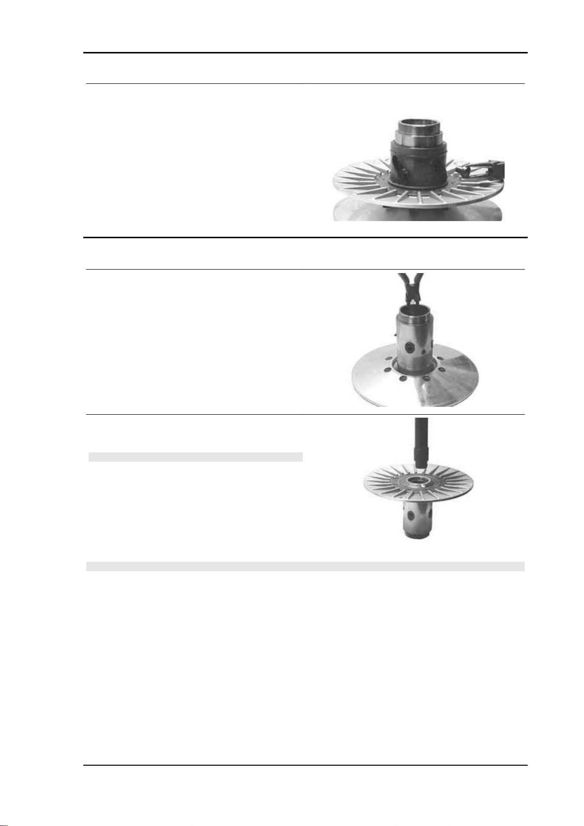
X9 Evolution 500 Engine
- Remove the 4 guide pins.
- Extract the moving driven half-pulley.
Removing the driven half-pulley bearing
- Check that the bushing is free from wear and
damage; otherwise replace the fixed driven halfpulley.
- Remove the lock ring using pliers.
- Using the special tool inserted through the roller
bearing, pull out the ball bearing.
N.B.
PROPERLY SUPPORT THE PULLEY TO PREVENT DAM-
AGING THE THREADING.
Specific tooling
020376Y Adaptor handle
020456Y Ø 24 mm adaptor
020363Y 20 mm guide
N.B.
IF YOU NEED TO OVERHAUL THE BEARINGS ON AN ASSEMBLED DRIVEN PULLEY UNIT, IT IS
NECESSARY TO SUPPORT THE UNIT BY THE BELL
Specific tooling
001467Y002 Driver for OD 73 mm bearing
ENG - 95
Page 96

Engine X9 Evolution 500
- Remove the roller bearing using the special tool,
supporting the fixed half-pulley with the bell.
Specific tooling
020376Y Adaptor handle
020375Y Adaptor 28 x 30 mm
020364Y 25-mm guide
001467Y002 Driver for OD 73 mm bearing
Inspecting the driven fixed half-pulley
- Check that the belt contact surface is free from
wear.
- Measure the outer diameter of the pulley bushing.
Characteristic
Minimum admissible diameter
49.91 mm
Standard diameter:
50.00 -0.015 -0.035 mm
Inspecting the driven sliding half-pulley
- Check that the belt contact surface is free from
wear.
- Remove the 2 inside sealing rings and the 2 outside O-rings.
- Measure the movable half-pulley bushing inside
diameter.
Characteristic
Maximum admissible diameter:
50.05 mm
Standard diameter:
50.00 +0.035 0.00 mm
Refitting the driven half-pulley bearing
- Install a new roller bearing using the special tool.
N.B.
PLACE THE BEARING WITH THE WRITINGS AND THE EMBEDDED OIL GUARD FACING OUTWARDS.
- Properly support the half-pulley to prevent damaging the threading.
ENG - 96
Page 97

X9 Evolution 500 Engine
If you are working on the driven pulley unit fully assembled, use the special tool.
Specific tooling
020478Y Punch for driven pulley roller casing
001467Y002 Driver for OD 73 mm bearing
- Install a new ball bearing using the special tool.
Specific tooling
020376Y Adaptor handle
020477Y Adaptor 37 mm
020363Y 20 mm guide
- Insert the Seeger lock ring.
Refitting the driven pulley
- Insert the new oil guards
- Insert the new O-rings
N.B.
O-RINGS ARE OF TWO SIZES. THE LARGE ONE IS INSTALLED ON THE MACHINING END RADIUS, AT THE BASE OF THE HALF-PULLEY.
- Install the half-pulley on the bushing being careful
not to damage the top sealing ring during the introduction.
- Make sure the pins and collar are not worn, reassemble the pins and collar.
- Using a bent beak greaser, lubricate the driven pulley unit with about 10 gr. of grease, this operation
should be carried out through one of the two holes into the bushing to obtain the exit of the grease from
the opposite hole. This operation is necessary to avoid the presence of grease beyond the O-rings.
Recommended products
AGIP GREASE SM 2 Grease for the tone wheel revolving ring
ENG - 97
Page 98

Engine X9 Evolution 500
Soap-based lithium grease containing NLGI 2 Molybdenum disulphide; ISO-L-XBCHB2, DIN KF2K-20
Inspecting the clutch spring
- Measure the length of the spring, while it is relaxed.
Characteristic
Standard length:
125.5 mm
Admissible limit after use:
120 mm
- Check the thickness of the clutch mass friction material.
Characteristic
Minimum thickness permitted:
1 mm
- The masses must exhibit no traces of lubricants;
in that case, check the driven pulley unit seals.
N.B.
UPON RUNNING-IN, THE MASSES MUST EXHIBIT A CENTRAL CONTACT SURFACE AND MUST
NOT BE DIFFERENT FROM ONE ANOTHER. VARIOUS CONDITIONS CAN CAUSE THE CLUTCH
TO TEAR.
- Do not open the masses using tools to prevent a variation in the return spring load.
ENG - 98
Page 99
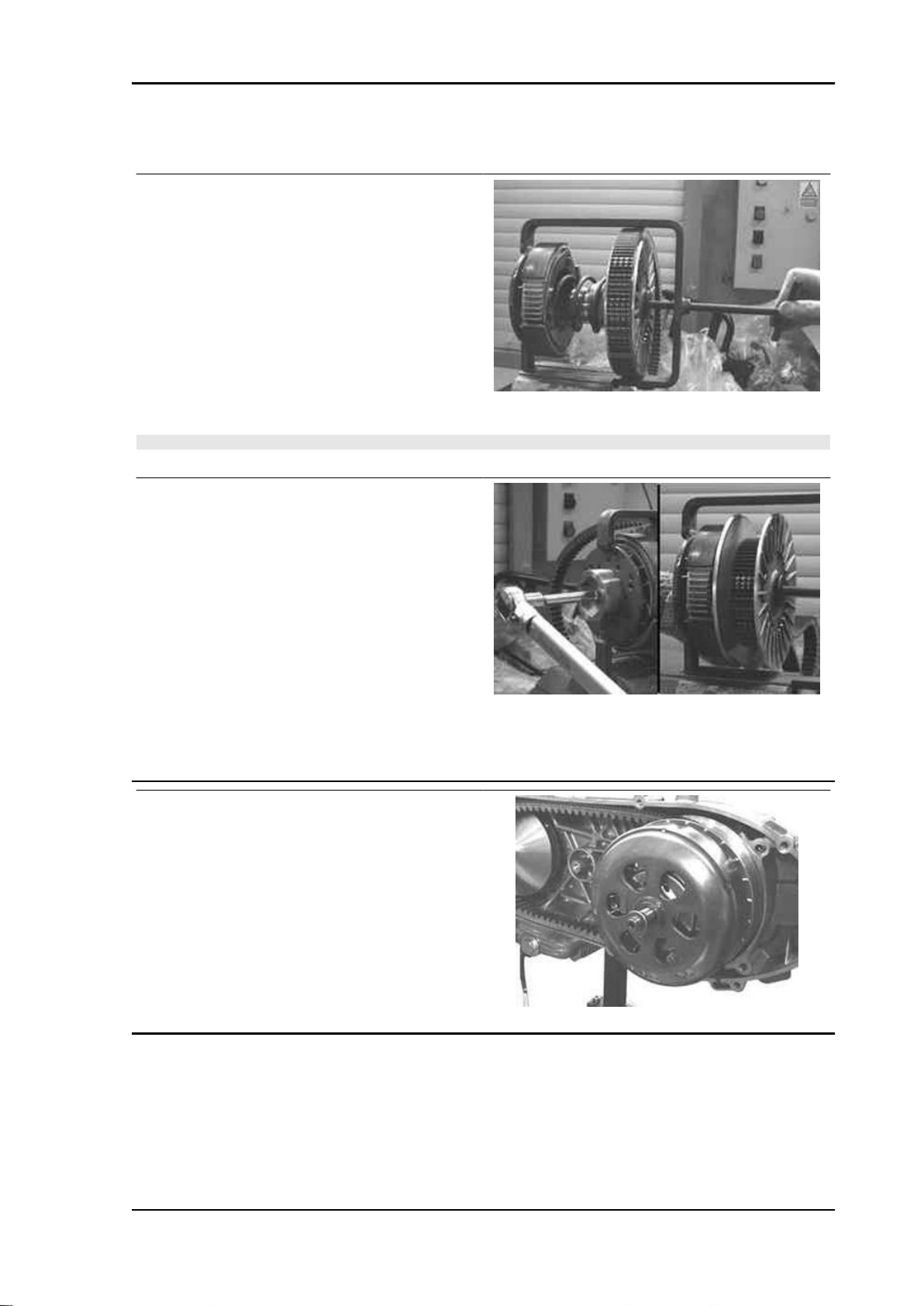
X9 Evolution 500 Engine
Refitting the clutch
- Prepare the special tool as for removal;
- Preassemble the driven pulley unit with the drive
belt according to its direction of rotation;
- Insert the driven pulley unit, the spring with
sheath and clutch into the tool.
Specific tooling
020444Y Tool for fitting/ removing the driven
pulley clutch
- Compress the spring and insert the clutch on the driven pulley bushing.
N.B.
BE CAREFUL NOT TO DAMAGE THE SHEATH OR THE BUSHING THREADED END.
- Tighten the ring nut by hand and complete the
tightening using the special wrench to the prescribed torque.
Specific tooling
020444Y Tool for fitting/ removing the driven
pulley clutch
Locking torques (N*m)
Clutch ring nut 65 - 75
- To facilitate reassembly on the engine, turn the moving driven pulley and insert the belt onto the smaller
diameter.
Bell assembly
- Install the bell and the spacer.
ENG - 99
Page 100

Engine X9 Evolution 500
Refitting the driven pulley
- Install the driven pulley assembly with belt.
Drive-belt
- Check that the driving belt is not damaged.
- Check the width of the belt.
Characteristic
Minimum width:
25 mm
Standard width:
26.2 mm
Removing the driving pulley
- Using a 27 mm wrench, turn the central pulley nut
to horizontally align the central inside holes and
install the special tool.
Specific tooling
020474Y Driving pulley lock wrench
ENG - 100
 Loading...